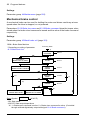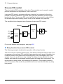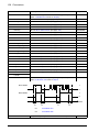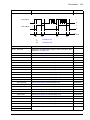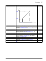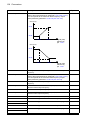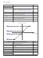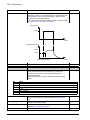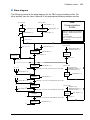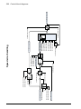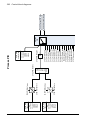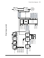
1
ACS850 Firmware Manual ACS850 Standard Control Program ACS850 drive manuals DRIVE HARDWARE MANUAL* ACS850-04 Drive Modules (1.1 to 45 kW) Hardware Manual – 3AUA0000045496 (English) ACS850-04 Drive Modules (55 to 160 kW, 75 to 200 hp) Hardware Manual – 3AUA0000045487 (English) ACS850-04 Drive Modules (200 to 500 kW, 250 to 600 hp) Hardware Manual – 3AUA0000026234 (English) DRIVE FIRMWARE MANUALS ACS850 Standard Control Program Firmware Manual** – 3AUA0000045497 (English). OPTION MANUALS* FIO-01 Digital I/O Extension User’s Manual – 3AFE68784921 (English) FIO-11 Analog I/O Extension User’s Manual – 3AFE68784930 (English) FIO-21 Analog I/O Extension User’s Manual – 3AUA0000031061 (English) FEN-01 TTL Encoder Interface User’s Manual – 3AFE68784603 (English) FEN-11 Absolute Encoder Interface User’s Manual – 3AFE68784841 (English) FEN-21 Resolver Interface User’s Manual – 3AFE68784859 (English) FEN-31 HTL Encoder Interface User’s Manual – 3AUA0000031044 (English) *The delivery includes a multilingual quick installation guide. **The delivery includes a multilingual quick start-up guide. Firmware Manual ACS850 Standard Control Program Table of contents 3AUA0000045497 Rev C EN EFFECTIVE: 2009-07-20 © 2009 ABB Oy. All Rights Reserved. Table of contents 5 Table of contents ACS850 drive manuals . . . . . . . . . . . . . . . . . . . . . . . . . . . . . . . . . . . . . . . . . . . . . . . . . . . . . . . 2 1. About the manual What this chapter contains . . . . . . . . . . . . . . . . . . . . . . . . . . . . . . . . . . . . . . . . . . . . . . . . . . . Compatibility . . . . . . . . . . . . . . . . . . . . . . . . . . . . . . . . . . . . . . . . . . . . . . . . . . . . . . . . . . . . . . Safety instructions . . . . . . . . . . . . . . . . . . . . . . . . . . . . . . . . . . . . . . . . . . . . . . . . . . . . . . . . . . Reader . . . . . . . . . . . . . . . . . . . . . . . . . . . . . . . . . . . . . . . . . . . . . . . . . . . . . . . . . . . . . . . . . . . Contents . . . . . . . . . . . . . . . . . . . . . . . . . . . . . . . . . . . . . . . . . . . . . . . . . . . . . . . . . . . . . . . . . Related manuals . . . . . . . . . . . . . . . . . . . . . . . . . . . . . . . . . . . . . . . . . . . . . . . . . . . . . . . . . . . 2. The ACS850 control panel 11 11 11 11 12 12 Safety What this chapter contains . . . . . . . . . . . . . . . . . . . . . . . . . . . . . . . . . . . . . . . . . . . . . . . . . . . Features . . . . . . . . . . . . . . . . . . . . . . . . . . . . . . . . . . . . . . . . . . . . . . . . . . . . . . . . . . . . . . . . . Installation . . . . . . . . . . . . . . . . . . . . . . . . . . . . . . . . . . . . . . . . . . . . . . . . . . . . . . . . . . . . . . . . Mechanical installation . . . . . . . . . . . . . . . . . . . . . . . . . . . . . . . . . . . . . . . . . . . . . . . . . . . Electrical installation . . . . . . . . . . . . . . . . . . . . . . . . . . . . . . . . . . . . . . . . . . . . . . . . . . . . . Layout . . . . . . . . . . . . . . . . . . . . . . . . . . . . . . . . . . . . . . . . . . . . . . . . . . . . . . . . . . . . . . . . . . . Status line . . . . . . . . . . . . . . . . . . . . . . . . . . . . . . . . . . . . . . . . . . . . . . . . . . . . . . . . . . . . . Operating instructions . . . . . . . . . . . . . . . . . . . . . . . . . . . . . . . . . . . . . . . . . . . . . . . . . . . . . . . Basics of operation . . . . . . . . . . . . . . . . . . . . . . . . . . . . . . . . . . . . . . . . . . . . . . . . . . . . . . List of tasks . . . . . . . . . . . . . . . . . . . . . . . . . . . . . . . . . . . . . . . . . . . . . . . . . . . . . . . . . . . . Help and panel version – Any mode . . . . . . . . . . . . . . . . . . . . . . . . . . . . . . . . . . . . . . . . . Basic operations – Any mode . . . . . . . . . . . . . . . . . . . . . . . . . . . . . . . . . . . . . . . . . . . . . . Output mode . . . . . . . . . . . . . . . . . . . . . . . . . . . . . . . . . . . . . . . . . . . . . . . . . . . . . . . . . . . Parameters . . . . . . . . . . . . . . . . . . . . . . . . . . . . . . . . . . . . . . . . . . . . . . . . . . . . . . . . . . . . Assistants . . . . . . . . . . . . . . . . . . . . . . . . . . . . . . . . . . . . . . . . . . . . . . . . . . . . . . . . . . . . . Changed Parameters . . . . . . . . . . . . . . . . . . . . . . . . . . . . . . . . . . . . . . . . . . . . . . . . . . . . Fault Logger . . . . . . . . . . . . . . . . . . . . . . . . . . . . . . . . . . . . . . . . . . . . . . . . . . . . . . . . . . . Time & Date . . . . . . . . . . . . . . . . . . . . . . . . . . . . . . . . . . . . . . . . . . . . . . . . . . . . . . . . . . . Parameter Backup . . . . . . . . . . . . . . . . . . . . . . . . . . . . . . . . . . . . . . . . . . . . . . . . . . . . . . I/O Settings . . . . . . . . . . . . . . . . . . . . . . . . . . . . . . . . . . . . . . . . . . . . . . . . . . . . . . . . . . . . Reference Edit . . . . . . . . . . . . . . . . . . . . . . . . . . . . . . . . . . . . . . . . . . . . . . . . . . . . . . . . . Drive Info . . . . . . . . . . . . . . . . . . . . . . . . . . . . . . . . . . . . . . . . . . . . . . . . . . . . . . . . . . . . . . Parameter Change Log . . . . . . . . . . . . . . . . . . . . . . . . . . . . . . . . . . . . . . . . . . . . . . . . . . . 13 13 14 14 14 15 16 17 17 18 19 20 21 23 30 32 34 36 38 46 48 49 50 3. Control locations and operating modes What this chapter contains . . . . . . . . . . . . . . . . . . . . . . . . . . . . . . . . . . . . . . . . . . . . . . . . . . . Local control vs. external control . . . . . . . . . . . . . . . . . . . . . . . . . . . . . . . . . . . . . . . . . . . . . . . Local control . . . . . . . . . . . . . . . . . . . . . . . . . . . . . . . . . . . . . . . . . . . . . . . . . . . . . . . . . . . External control . . . . . . . . . . . . . . . . . . . . . . . . . . . . . . . . . . . . . . . . . . . . . . . . . . . . . . . . . Operating modes of the drive . . . . . . . . . . . . . . . . . . . . . . . . . . . . . . . . . . . . . . . . . . . . . . . . . Speed control mode . . . . . . . . . . . . . . . . . . . . . . . . . . . . . . . . . . . . . . . . . . . . . . . . . . . . . Torque control mode . . . . . . . . . . . . . . . . . . . . . . . . . . . . . . . . . . . . . . . . . . . . . . . . . . . . . Special control modes . . . . . . . . . . . . . . . . . . . . . . . . . . . . . . . . . . . . . . . . . . . . . . . . . . . . 53 54 54 55 55 55 55 55 6 Table of contents 4. Program features What this chapter contains . . . . . . . . . . . . . . . . . . . . . . . . . . . . . . . . . . . . . . . . . . . . . . . . . . . Application macros . . . . . . . . . . . . . . . . . . . . . . . . . . . . . . . . . . . . . . . . . . . . . . . . . . . . . . . . . Automatic fault resets . . . . . . . . . . . . . . . . . . . . . . . . . . . . . . . . . . . . . . . . . . . . . . . . . . . . . . . Autophasing . . . . . . . . . . . . . . . . . . . . . . . . . . . . . . . . . . . . . . . . . . . . . . . . . . . . . . . . . . . . . . Constant speeds . . . . . . . . . . . . . . . . . . . . . . . . . . . . . . . . . . . . . . . . . . . . . . . . . . . . . . . . . . Critical speeds . . . . . . . . . . . . . . . . . . . . . . . . . . . . . . . . . . . . . . . . . . . . . . . . . . . . . . . . . . . . DC voltage control . . . . . . . . . . . . . . . . . . . . . . . . . . . . . . . . . . . . . . . . . . . . . . . . . . . . . . . . . Overvoltage control . . . . . . . . . . . . . . . . . . . . . . . . . . . . . . . . . . . . . . . . . . . . . . . . . . . . . Undervoltage control . . . . . . . . . . . . . . . . . . . . . . . . . . . . . . . . . . . . . . . . . . . . . . . . . . . . Voltage control and trip limits . . . . . . . . . . . . . . . . . . . . . . . . . . . . . . . . . . . . . . . . . . . . . . Brake chopper . . . . . . . . . . . . . . . . . . . . . . . . . . . . . . . . . . . . . . . . . . . . . . . . . . . . . . . . . Drive-to-drive link . . . . . . . . . . . . . . . . . . . . . . . . . . . . . . . . . . . . . . . . . . . . . . . . . . . . . . . . . . Emergency stop . . . . . . . . . . . . . . . . . . . . . . . . . . . . . . . . . . . . . . . . . . . . . . . . . . . . . . . . . . . Encoder support . . . . . . . . . . . . . . . . . . . . . . . . . . . . . . . . . . . . . . . . . . . . . . . . . . . . . . . . . . . Energy optimizer . . . . . . . . . . . . . . . . . . . . . . . . . . . . . . . . . . . . . . . . . . . . . . . . . . . . . . . . . . Fieldbus control . . . . . . . . . . . . . . . . . . . . . . . . . . . . . . . . . . . . . . . . . . . . . . . . . . . . . . . . . . . Jogging . . . . . . . . . . . . . . . . . . . . . . . . . . . . . . . . . . . . . . . . . . . . . . . . . . . . . . . . . . . . . . . . . . Load analyzer . . . . . . . . . . . . . . . . . . . . . . . . . . . . . . . . . . . . . . . . . . . . . . . . . . . . . . . . . . . . . Peak value logger . . . . . . . . . . . . . . . . . . . . . . . . . . . . . . . . . . . . . . . . . . . . . . . . . . . . . . Amplitude loggers . . . . . . . . . . . . . . . . . . . . . . . . . . . . . . . . . . . . . . . . . . . . . . . . . . . . . . Maintenance counters . . . . . . . . . . . . . . . . . . . . . . . . . . . . . . . . . . . . . . . . . . . . . . . . . . . . . . Mechanical brake control . . . . . . . . . . . . . . . . . . . . . . . . . . . . . . . . . . . . . . . . . . . . . . . . . . . . Process PID control . . . . . . . . . . . . . . . . . . . . . . . . . . . . . . . . . . . . . . . . . . . . . . . . . . . . . . . . Sleep function for process PID control . . . . . . . . . . . . . . . . . . . . . . . . . . . . . . . . . . . . . . . Programmable analog inputs . . . . . . . . . . . . . . . . . . . . . . . . . . . . . . . . . . . . . . . . . . . . . . . . . Programmable analog outputs . . . . . . . . . . . . . . . . . . . . . . . . . . . . . . . . . . . . . . . . . . . . . . . . Programmable digital inputs and outputs . . . . . . . . . . . . . . . . . . . . . . . . . . . . . . . . . . . . . . . . Programmable relay outputs . . . . . . . . . . . . . . . . . . . . . . . . . . . . . . . . . . . . . . . . . . . . . . . . . Programmable protection functions . . . . . . . . . . . . . . . . . . . . . . . . . . . . . . . . . . . . . . . . . . . . Start interlock (parameter 10.20) . . . . . . . . . . . . . . . . . . . . . . . . . . . . . . . . . . . . . . . . . . . External fault (parameter 30.01) . . . . . . . . . . . . . . . . . . . . . . . . . . . . . . . . . . . . . . . . . . . Local control loss detection (parameter 30.03) . . . . . . . . . . . . . . . . . . . . . . . . . . . . . . . . Motor phase loss detection (parameter 30.04) . . . . . . . . . . . . . . . . . . . . . . . . . . . . . . . . Earth fault detection (parameter 30.05) . . . . . . . . . . . . . . . . . . . . . . . . . . . . . . . . . . . . . . Supply phase loss detection (parameter 30.06) . . . . . . . . . . . . . . . . . . . . . . . . . . . . . . . . Safe Torque Off detection (parameter 30.07) . . . . . . . . . . . . . . . . . . . . . . . . . . . . . . . . . Switched supply and motor cabling (parameter 30.08) . . . . . . . . . . . . . . . . . . . . . . . . . . Stall protection (parameters 30.09…30.12) . . . . . . . . . . . . . . . . . . . . . . . . . . . . . . . . . . . Scalar motor control . . . . . . . . . . . . . . . . . . . . . . . . . . . . . . . . . . . . . . . . . . . . . . . . . . . . . . . . IR compensation for a scalar controlled drive . . . . . . . . . . . . . . . . . . . . . . . . . . . . . . . . . Signal supervision . . . . . . . . . . . . . . . . . . . . . . . . . . . . . . . . . . . . . . . . . . . . . . . . . . . . . . . . . Speed controller tuning . . . . . . . . . . . . . . . . . . . . . . . . . . . . . . . . . . . . . . . . . . . . . . . . . . . . . Thermal motor protection . . . . . . . . . . . . . . . . . . . . . . . . . . . . . . . . . . . . . . . . . . . . . . . . . . . . Thermal motor protection model . . . . . . . . . . . . . . . . . . . . . . . . . . . . . . . . . . . . . . . . . . . Temperature measurement . . . . . . . . . . . . . . . . . . . . . . . . . . . . . . . . . . . . . . . . . . . . . . . Settings . . . . . . . . . . . . . . . . . . . . . . . . . . . . . . . . . . . . . . . . . . . . . . . . . . . . . . . . . . . . . . Timers . . . . . . . . . . . . . . . . . . . . . . . . . . . . . . . . . . . . . . . . . . . . . . . . . . . . . . . . . . . . . . . . . . User-definable load curve . . . . . . . . . . . . . . . . . . . . . . . . . . . . . . . . . . . . . . . . . . . . . . . . . . . User-definable U/f curve . . . . . . . . . . . . . . . . . . . . . . . . . . . . . . . . . . . . . . . . . . . . . . . . . . . . . 57 58 58 58 59 59 59 59 60 60 61 61 62 62 62 63 63 64 64 64 65 66 70 70 71 72 72 72 72 72 73 73 73 73 73 73 73 73 74 74 74 74 76 76 76 77 77 79 79 Table of contents 7 5. Application macros What this chapter contains . . . . . . . . . . . . . . . . . . . . . . . . . . . . . . . . . . . . . . . . . . . . . . . . . . . General . . . . . . . . . . . . . . . . . . . . . . . . . . . . . . . . . . . . . . . . . . . . . . . . . . . . . . . . . . . . . . . . . . Factory macro . . . . . . . . . . . . . . . . . . . . . . . . . . . . . . . . . . . . . . . . . . . . . . . . . . . . . . . . . . . . . Default control connections for the Factory macro . . . . . . . . . . . . . . . . . . . . . . . . . . . . . . Hand/Auto macro . . . . . . . . . . . . . . . . . . . . . . . . . . . . . . . . . . . . . . . . . . . . . . . . . . . . . . . . . . . Default control connections for the Hand/Auto macro . . . . . . . . . . . . . . . . . . . . . . . . . . . . PID control macro . . . . . . . . . . . . . . . . . . . . . . . . . . . . . . . . . . . . . . . . . . . . . . . . . . . . . . . . . . Default control connections for the PID control macro . . . . . . . . . . . . . . . . . . . . . . . . . . . Torque control macro . . . . . . . . . . . . . . . . . . . . . . . . . . . . . . . . . . . . . . . . . . . . . . . . . . . . . . . Default control connections for the Torque control macro . . . . . . . . . . . . . . . . . . . . . . . . Sequential control macro . . . . . . . . . . . . . . . . . . . . . . . . . . . . . . . . . . . . . . . . . . . . . . . . . . . . . Default control connections for the Sequential control macro . . . . . . . . . . . . . . . . . . . . . . 81 81 82 83 84 85 86 87 88 89 90 92 6. Parameters What this chapter contains . . . . . . . . . . . . . . . . . . . . . . . . . . . . . . . . . . . . . . . . . . . . . . . . . . . 93 Terms and abbreviations . . . . . . . . . . . . . . . . . . . . . . . . . . . . . . . . . . . . . . . . . . . . . . . . . . . . . 93 Parameter listing . . . . . . . . . . . . . . . . . . . . . . . . . . . . . . . . . . . . . . . . . . . . . . . . . . . . . . . . . . . 94 01 Actual values . . . . . . . . . . . . . . . . . . . . . . . . . . . . . . . . . . . . . . . . . . . . . . . . . . . . . . . . 94 02 I/O values . . . . . . . . . . . . . . . . . . . . . . . . . . . . . . . . . . . . . . . . . . . . . . . . . . . . . . . . . . . 95 03 Control values . . . . . . . . . . . . . . . . . . . . . . . . . . . . . . . . . . . . . . . . . . . . . . . . . . . . . . 101 04 Appl values . . . . . . . . . . . . . . . . . . . . . . . . . . . . . . . . . . . . . . . . . . . . . . . . . . . . . . . . . 102 06 Drive status . . . . . . . . . . . . . . . . . . . . . . . . . . . . . . . . . . . . . . . . . . . . . . . . . . . . . . . . 103 08 Alarms & faults . . . . . . . . . . . . . . . . . . . . . . . . . . . . . . . . . . . . . . . . . . . . . . . . . . . . . . 106 09 System info . . . . . . . . . . . . . . . . . . . . . . . . . . . . . . . . . . . . . . . . . . . . . . . . . . . . . . . . 108 10 Start/stop . . . . . . . . . . . . . . . . . . . . . . . . . . . . . . . . . . . . . . . . . . . . . . . . . . . . . . . . . . 109 11 Start/stop mode . . . . . . . . . . . . . . . . . . . . . . . . . . . . . . . . . . . . . . . . . . . . . . . . . . . . . 116 12 Operating mode . . . . . . . . . . . . . . . . . . . . . . . . . . . . . . . . . . . . . . . . . . . . . . . . . . . . . 118 13 Analogue inputs . . . . . . . . . . . . . . . . . . . . . . . . . . . . . . . . . . . . . . . . . . . . . . . . . . . . . 119 14 Digital I/O . . . . . . . . . . . . . . . . . . . . . . . . . . . . . . . . . . . . . . . . . . . . . . . . . . . . . . . . . . 126 15 Analogue outputs . . . . . . . . . . . . . . . . . . . . . . . . . . . . . . . . . . . . . . . . . . . . . . . . . . . . 139 16 System . . . . . . . . . . . . . . . . . . . . . . . . . . . . . . . . . . . . . . . . . . . . . . . . . . . . . . . . . . . . 145 19 Speed calculation . . . . . . . . . . . . . . . . . . . . . . . . . . . . . . . . . . . . . . . . . . . . . . . . . . . . 147 20 Limits . . . . . . . . . . . . . . . . . . . . . . . . . . . . . . . . . . . . . . . . . . . . . . . . . . . . . . . . . . . . . 150 21 Speed ref . . . . . . . . . . . . . . . . . . . . . . . . . . . . . . . . . . . . . . . . . . . . . . . . . . . . . . . . . . 152 22 Speed ref ramp . . . . . . . . . . . . . . . . . . . . . . . . . . . . . . . . . . . . . . . . . . . . . . . . . . . . . 155 23 Speed ctrl . . . . . . . . . . . . . . . . . . . . . . . . . . . . . . . . . . . . . . . . . . . . . . . . . . . . . . . . . . 158 24 Torque ref . . . . . . . . . . . . . . . . . . . . . . . . . . . . . . . . . . . . . . . . . . . . . . . . . . . . . . . . . . 166 25 Critical speed . . . . . . . . . . . . . . . . . . . . . . . . . . . . . . . . . . . . . . . . . . . . . . . . . . . . . . . 167 26 Constant speeds . . . . . . . . . . . . . . . . . . . . . . . . . . . . . . . . . . . . . . . . . . . . . . . . . . . . 168 27 Process PID . . . . . . . . . . . . . . . . . . . . . . . . . . . . . . . . . . . . . . . . . . . . . . . . . . . . . . . . 170 30 Fault functions . . . . . . . . . . . . . . . . . . . . . . . . . . . . . . . . . . . . . . . . . . . . . . . . . . . . . . 174 31 Mot therm prot . . . . . . . . . . . . . . . . . . . . . . . . . . . . . . . . . . . . . . . . . . . . . . . . . . . . . . 177 32 Automatic reset . . . . . . . . . . . . . . . . . . . . . . . . . . . . . . . . . . . . . . . . . . . . . . . . . . . . . 182 33 Supervision . . . . . . . . . . . . . . . . . . . . . . . . . . . . . . . . . . . . . . . . . . . . . . . . . . . . . . . . 183 34 User load curve . . . . . . . . . . . . . . . . . . . . . . . . . . . . . . . . . . . . . . . . . . . . . . . . . . . . . 186 35 Process variable . . . . . . . . . . . . . . . . . . . . . . . . . . . . . . . . . . . . . . . . . . . . . . . . . . . . . 188 36 Timed functions . . . . . . . . . . . . . . . . . . . . . . . . . . . . . . . . . . . . . . . . . . . . . . . . . . . . . 194 38 Flux ref . . . . . . . . . . . . . . . . . . . . . . . . . . . . . . . . . . . . . . . . . . . . . . . . . . . . . . . . . . . . 199 8 Table of contents 40 Motor control . . . . . . . . . . . . . . . . . . . . . . . . . . . . . . . . . . . . . . . . . . . . . . . . . . . . . . . 42 Mech brake ctrl . . . . . . . . . . . . . . . . . . . . . . . . . . . . . . . . . . . . . . . . . . . . . . . . . . . . . 44 Maintenance . . . . . . . . . . . . . . . . . . . . . . . . . . . . . . . . . . . . . . . . . . . . . . . . . . . . . . . 45 Energy optimising . . . . . . . . . . . . . . . . . . . . . . . . . . . . . . . . . . . . . . . . . . . . . . . . . . . 47 Voltage ctrl . . . . . . . . . . . . . . . . . . . . . . . . . . . . . . . . . . . . . . . . . . . . . . . . . . . . . . . . 48 Brake chopper . . . . . . . . . . . . . . . . . . . . . . . . . . . . . . . . . . . . . . . . . . . . . . . . . . . . . . 49 Data storage . . . . . . . . . . . . . . . . . . . . . . . . . . . . . . . . . . . . . . . . . . . . . . . . . . . . . . . 50 Fieldbus . . . . . . . . . . . . . . . . . . . . . . . . . . . . . . . . . . . . . . . . . . . . . . . . . . . . . . . . . . . 51 FBA settings . . . . . . . . . . . . . . . . . . . . . . . . . . . . . . . . . . . . . . . . . . . . . . . . . . . . . . . 52 FBA data in . . . . . . . . . . . . . . . . . . . . . . . . . . . . . . . . . . . . . . . . . . . . . . . . . . . . . . . . 53 FBA data out . . . . . . . . . . . . . . . . . . . . . . . . . . . . . . . . . . . . . . . . . . . . . . . . . . . . . . . 56 Panel display . . . . . . . . . . . . . . . . . . . . . . . . . . . . . . . . . . . . . . . . . . . . . . . . . . . . . . . 57 D2D communication . . . . . . . . . . . . . . . . . . . . . . . . . . . . . . . . . . . . . . . . . . . . . . . . . 64 Load analyzer . . . . . . . . . . . . . . . . . . . . . . . . . . . . . . . . . . . . . . . . . . . . . . . . . . . . . . 90 Enc module sel . . . . . . . . . . . . . . . . . . . . . . . . . . . . . . . . . . . . . . . . . . . . . . . . . . . . . 91 Absol enc conf . . . . . . . . . . . . . . . . . . . . . . . . . . . . . . . . . . . . . . . . . . . . . . . . . . . . . . 92 Resolver conf . . . . . . . . . . . . . . . . . . . . . . . . . . . . . . . . . . . . . . . . . . . . . . . . . . . . . . 93 Pulse enc conf . . . . . . . . . . . . . . . . . . . . . . . . . . . . . . . . . . . . . . . . . . . . . . . . . . . . . . 94 Ext IO conf . . . . . . . . . . . . . . . . . . . . . . . . . . . . . . . . . . . . . . . . . . . . . . . . . . . . . . . . 95 Hw configuration . . . . . . . . . . . . . . . . . . . . . . . . . . . . . . . . . . . . . . . . . . . . . . . . . . . . 97 User motor par . . . . . . . . . . . . . . . . . . . . . . . . . . . . . . . . . . . . . . . . . . . . . . . . . . . . . 99 Start-up data . . . . . . . . . . . . . . . . . . . . . . . . . . . . . . . . . . . . . . . . . . . . . . . . . . . . . . . 200 201 205 211 212 212 213 214 216 217 217 217 218 220 224 225 228 228 229 229 230 231 7. Additional parameter data What this chapter contains . . . . . . . . . . . . . . . . . . . . . . . . . . . . . . . . . . . . . . . . . . . . . . . . . . Terms and abbreviations . . . . . . . . . . . . . . . . . . . . . . . . . . . . . . . . . . . . . . . . . . . . . . . . . . . Fieldbus addresses . . . . . . . . . . . . . . . . . . . . . . . . . . . . . . . . . . . . . . . . . . . . . . . . . . . . . . . Pointer parameter format in fieldbus communication . . . . . . . . . . . . . . . . . . . . . . . . . . . . . . 32-bit integer value pointers . . . . . . . . . . . . . . . . . . . . . . . . . . . . . . . . . . . . . . . . . . . . . . 32-bit integer bit pointers . . . . . . . . . . . . . . . . . . . . . . . . . . . . . . . . . . . . . . . . . . . . . . . . Parameter groups 1…9 . . . . . . . . . . . . . . . . . . . . . . . . . . . . . . . . . . . . . . . . . . . . . . . . . . . . Parameter groups 10…99 . . . . . . . . . . . . . . . . . . . . . . . . . . . . . . . . . . . . . . . . . . . . . . . . . . 237 237 238 238 238 239 240 243 8. Fault tracing What this chapter contains . . . . . . . . . . . . . . . . . . . . . . . . . . . . . . . . . . . . . . . . . . . . . . . . . . Safety . . . . . . . . . . . . . . . . . . . . . . . . . . . . . . . . . . . . . . . . . . . . . . . . . . . . . . . . . . . . . . . . . . Alarm and fault indications . . . . . . . . . . . . . . . . . . . . . . . . . . . . . . . . . . . . . . . . . . . . . . . . . . How to reset . . . . . . . . . . . . . . . . . . . . . . . . . . . . . . . . . . . . . . . . . . . . . . . . . . . . . . . . . . . . . Fault history . . . . . . . . . . . . . . . . . . . . . . . . . . . . . . . . . . . . . . . . . . . . . . . . . . . . . . . . . . . . . Alarm messages generated by the drive . . . . . . . . . . . . . . . . . . . . . . . . . . . . . . . . . . . . . . . Fault messages generated by the drive . . . . . . . . . . . . . . . . . . . . . . . . . . . . . . . . . . . . . . . . 259 259 259 260 260 260 268 9. Fieldbus control What this chapter contains . . . . . . . . . . . . . . . . . . . . . . . . . . . . . . . . . . . . . . . . . . . . . . . . . . System overview . . . . . . . . . . . . . . . . . . . . . . . . . . . . . . . . . . . . . . . . . . . . . . . . . . . . . . . . . Setting up communication through a fieldbus adapter module . . . . . . . . . . . . . . . . . . . . . . . Drive control parameters . . . . . . . . . . . . . . . . . . . . . . . . . . . . . . . . . . . . . . . . . . . . . . . . . . . The fieldbus control interface . . . . . . . . . . . . . . . . . . . . . . . . . . . . . . . . . . . . . . . . . . . . . . . . 277 278 279 281 282 Table of contents 9 The Control Word and the Status Word . . . . . . . . . . . . . . . . . . . . . . . . . . . . . . . . . . . . . Actual values . . . . . . . . . . . . . . . . . . . . . . . . . . . . . . . . . . . . . . . . . . . . . . . . . . . . . . . . . . FBA communication profile . . . . . . . . . . . . . . . . . . . . . . . . . . . . . . . . . . . . . . . . . . . . . . . . . . Fieldbus references . . . . . . . . . . . . . . . . . . . . . . . . . . . . . . . . . . . . . . . . . . . . . . . . . . . . . State diagram . . . . . . . . . . . . . . . . . . . . . . . . . . . . . . . . . . . . . . . . . . . . . . . . . . . . . . . . . 283 283 283 284 285 10. Control block diagrams What this chapter contains . . . . . . . . . . . . . . . . . . . . . . . . . . . . . . . . . . . . . . . . . . . . . . . . . . Speed feedback . . . . . . . . . . . . . . . . . . . . . . . . . . . . . . . . . . . . . . . . . . . . . . . . . . . . . . . . . . . Speed reference modification and ramping . . . . . . . . . . . . . . . . . . . . . . . . . . . . . . . . . . . . . . Speed error handling . . . . . . . . . . . . . . . . . . . . . . . . . . . . . . . . . . . . . . . . . . . . . . . . . . . . . . . Torque reference modification, operating mode selection . . . . . . . . . . . . . . . . . . . . . . . . . . . Process PID . . . . . . . . . . . . . . . . . . . . . . . . . . . . . . . . . . . . . . . . . . . . . . . . . . . . . . . . . . . . . . Direct torque control . . . . . . . . . . . . . . . . . . . . . . . . . . . . . . . . . . . . . . . . . . . . . . . . . . . . . . . 287 288 289 290 291 292 293 Further information Product and service inquiries . . . . . . . . . . . . . . . . . . . . . . . . . . . . . . . . . . . . . . . . . . . . . . . . Product training . . . . . . . . . . . . . . . . . . . . . . . . . . . . . . . . . . . . . . . . . . . . . . . . . . . . . . . . . . . Providing feedback on ABB Drives manuals . . . . . . . . . . . . . . . . . . . . . . . . . . . . . . . . . . . . . Document library on the Internet . . . . . . . . . . . . . . . . . . . . . . . . . . . . . . . . . . . . . . . . . . . . . . 295 295 295 295 10 Table of contents About the manual 11 1 About the manual What this chapter contains The chapter describes the contents of the manual. It also contains information on the compatibility, safety and intended audience. Compatibility The manual is compatible with ACS850 standard control program. Safety instructions Follow all safety instructions delivered with the drive. • Read the complete safety instructions before you install, commission, or use the drive. The complete safety instructions are given at the beginning of the Hardware Manual. • Read the software function specific warnings and notes before changing the default settings of the function. For each function, the warnings and notes are given in this manual in the section describing the related user-adjustable parameters. Reader The reader of the manual is expected to know the standard electrical wiring practices, electronic components, and electrical schematic symbols. 12 About the manual Contents The manual consists of the following chapters: • The ACS850 control panel provides a description and instructions for use of the control panel. • Control locations and operating modes describes the control locations and operation modes of the drive. • Program features contains descriptions of the features of the ACS850 standard control program. • Application macros contains a short description of each macro together with a connection diagram. • Parameters describes the parameters of the drive. • Additional parameter data contains further information on the parameters. • Fault tracing lists the alarm (warning) and fault messages with possible causes and remedies. • Fieldbus control describes the communication to and from a fieldbus network. • Control block diagrams contains a graphical representation of the control program. Related manuals The delivery of the drive includes a multilingual Quick Start-up Guide. A complete list of related manuals is printed on the inside of the front cover. The ACS850 control panel 13 2 The ACS850 control panel What this chapter contains This chapter describes the features and operation of the ACS850 control panel. The control panel can be used to control the drive, read status data, and adjust parameters. Features • alphanumeric control panel with an LCD display • copy function – parameters can be copied to the control panel memory for later transfer to other drives or for backup of a particular system. • context sensitive help • real time clock. 14 The ACS850 control panel Installation Mechanical installation For mounting options, see the Hardware Manual of the drive. Instructions for mounting the control panel onto a cabinet door are available in ACS-CP-U Control Panel IP54 Mounting Platform Kit Installation Guide (3AUA0000049072 [English]). Electrical installation Use a CAT5 straight-through network cable with a maximum length of 3 meters. Suitable cables are available from ABB. For the control panel connector location on the drive, see the Hardware Manual of the drive. The ACS850 control panel 15 Layout 1 2a LOC LOC 2b 2c 3 7 30.10Hz 30.00rpm 30.00rpm 400RPM 10 Hz 120049 RPM 12.4 A0 50 A 405 10 dm3/s 7% DIR DIR . . . 12:45 00:00 5 6 9 MENU MENU 4 8 10 No. Use 1 Status LED – Green for normal operation. 2 LCD display – Divided into three main areas: Status line – variable, depending on the mode of operation, see section Status line on page 16. Center – variable; in general, shows signal and parameter values, menus or lists. Shows also faults and alarms. Bottom line – shows current functions of the two soft keys and, if enabled, the clock display. 3 Soft key 1 – Function depends on the context. The text in the lower left corner of the LCD display indicates the function. 4 Soft key 2 – Function depends on the context. The text in the lower right corner of the LCD display indicates the function. 5 Up – Scrolls up through a menu or list displayed in the center of the LCD display. Increments a value if a parameter is selected. Increments the reference value if the upper right corner is highlighted. Holding the key down changes the value faster. 6 Down – Scrolls down through a menu or list displayed in the center of the LCD display. Decrements a value if a parameter is selected. Decrements the reference value if the upper right corner is highlighted. Holding the key down changes the value faster. 7 LOC/REM – Changes between local and remote control of the drive. 8 Help – Displays context sensitive information when the key is pressed. The information displayed describes the item currently highlighted in the center of the display. 9 STOP – Stops the drive in local control. 10 START – Starts the drive in local control. 16 The ACS850 control panel Status line The top line of the LCD display shows the basic status information of the drive. LOC 1 30.00rpm 2 4 LOC 1 MAIN MENU 2 3 1 4 No. Field Alternatives Significance 1 Control location LOC Drive control is local, that is, from the control panel. REM Drive control is remote, such as the drive I/O or fieldbus. 2 State Forward shaft direction Reverse shaft direction Rotating arrow Drive is running at reference. Dotted rotating arrow Drive is running but not at reference. Stationary arrow Drive is stopped. Dotted stationary arrow Start command is present, but the motor is not running, e.g. because start enable signal is missing. 3 Panel operation mode • Name of the current mode • Name of the list or menu shown • Name of the operation state, e.g. REF EDIT. 4 Reference value or number of the selected item • Reference value in the Output mode • Number of the highlighted item, e.g mode, parameter group or fault. The ACS850 control panel 17 Operating instructions Basics of operation You operate the control panel with menus and keys. The keys include two contextsensitive soft keys, whose current function is indicated by the text shown in the display above each key. You select an option, e.g. operation mode or parameter, by entering the MENU state using soft key 2, and then by scrolling the and arrow keys until the option is highlighted and then pressing the relevant soft key. With the right soft key you usually enter a mode, accept an option or save the changes. The left soft key is used to cancel the made changes and return to the previous operation level. The Control Panel has ten options in the Main menu: Parameters, Assistants, Changed Par, Fault Logger, Time & Date, Parameter Backup, I/O Settings, Reference Edit, Drive Info and Parameter Change Log. In addition, the control panel has an Output mode, which is used as default. Also, when a fault or alarm occurs, the panel goes automatically to the Fault mode showing the fault or alarm. You can reset the fault in the Output or Fault mode. The operation in these modes and options is described in this chapter. Initially, the panel is in the Output mode, where you can start, stop, change the direction, switch between local and remote control, modify the reference value and monitor up to three actual values. To do other tasks, go first to the Main menu and select the appropriate option on the menu. The status line (see section Status line on page 11) shows the name of the current menu, mode, item or state. 30.00rpm LOC DIR LOC 49. 10 0. 50 10.7 00:00 Hz A % MENU MAIN MENU 1 PARAMETERS ASSISTANTS CHANGED PAR EXIT 00:00 ENTER 18 The ACS850 control panel List of tasks The table below lists common tasks, the mode in which you can perform them, abbreviations of the options in the Main menu and the page number where the steps to do the task are described in detail. Task Mode / Main menu option Abbreviations of the Main menu options * Page How to get help Any - 19 How to find out the panel version Any - 19 How to start and stop the drive Output - 20 How to switch between local and remote control Any - 20 How to change the direction of the motor rotation Any - 21 How to set the speed, frequency, torque or position reference in the Output mode Output - 21 How to adjust the display contrast Output - 22 How to change the value of a parameter Parameters PARAMETERS 23 How to change the value of value pointer parameters Parameters PARAMETERS 24 How to change the value of bit pointer parameter to point to the value of a bit in another signal Parameters PARAMETERS 26 How to change the value of bit pointer parameter to fixed 0 (FALSE) or 1 (TRUE) Parameters PARAMETERS 28 How to select the monitored signals Parameters PARAMETERS 29 How to do guided tasks (specification of related parameter sets) with assistants Assistants ASSISTANTS 30 How to view and edit changed parameters Changed Parameters CHANGED PAR 32 How to view faults Fault Logger FAULT LOGGER 34 How to reset faults and alarms Fault Logger FAULT LOGGER 35 How to show/hide the clock, change date and time formats, set the clock and enable/disable automatic clock transitions according to the daylight saving changes Time & Date TIME & DATE 36 How to copy parameters from the drive to the control panel Parameter Backup PAR BACKUP 38 How to restore parameters from the control panel to the drive Parameter Backup PAR BACKUP 38 How to view backup information Parameter Backup PAR BACKUP 44 How to edit and change parameter settings related to I/O Settings I/O terminals I/O SETTINGS 46 How to edit reference value Reference Edit REF EDIT 48 How to view drive info Drive Info DRIVE INFO 49 How to view and edit recently changed parameters Parameter Change Log PAR CHG LOG 50 * Main menu options actually shown in the control panel. The ACS850 control panel 19 Help and panel version – Any mode How to get help Step Action Display 1. Press ? to read the context-sensitive help text for the item that is highlighted. LOC TIME & DATE 6 TIME FORMAT DATE FORMAT SET TIME SET DATE DAYLIGHT SAVING 00:00 SEL EXIT If help text exists for the item, it is shown on the display. LOC HELP Use daylight saving to enable or disable automatic clock adjustment according to daylight saving EXIT 00:00 2. If the whole text is not visible, scroll the lines with keys and . LOC HELP to enable or disable automatic clock adjustment according to daylight saving changes EXIT 00:00 3. After reading the text, return to the previous display by EXIT pressing . LOC TIME & DATE 6 TIME FORMAT DATE FORMAT SET TIME SET DATE DAYLIGHT SAVING EXIT 00:00 SEL How to find out the panel version Step Action 1. If the power is switched on, switch it off. - If the panel cable can be disconnected easily, unplug the panel cable from the control panel, OR - if the panel cable can not be disconnected easily, switch off the control board or the drive. 2. Keep key ? depressed while you switch on the power and read the information. The display shows the following panel information: Panel SW: Panel firmware version ROM CRC: Panel ROM check sum Flash Rev: Flash content version Flash content comment. When you release the ? key, the panel goes to the Output mode. Display PANEL VERSION INFO Panel SW: x.xx ROM CRC: xxxxxxxxxx Flash Rev: x.xx xxxxxxxxxxxxxxxxxxxxx xxxxxxxxxxxxxxxxxxxxx 20 The ACS850 control panel Basic operations – Any mode How to start, stop and switch between local and remote control You can start, stop and switch between local and remote control in any mode. To be able to start or stop the drive by using the control panel, the drive must be in local control. Step Action Display 1. To switch between remote control (REM shown on the status line) and local control (LOC shown on the status line), press LOC REM . LOC MESSAGE Switching to the local control mode. Note: Switching to local control can be prevented with parameter 16.01 Local lock. 00:00 The very first time the drive is powered up, it is in remote control (REM) and controlled through the drive I/O terminals. To switch to local control (LOC) and control the drive using the control panel, press LOC REM . The result depends on how long you press the key: If you release the key immediately (the display flashes “Switching to the local control mode”), the drive stops. Set the local control reference as instructed on page 21. If you press the key until the text “Keep running” appears, the drive continues running as before. The drive copies the current remote values for the run/stop status and the reference, and uses them as the initial local control settings. To stop the drive in local control, press . The arrow ( or stops rotating. ) on the status line To start the drive in local control, press . The arrow ( or ) on the status line starts rotating. It is dotted until the drive reaches the setpoint. The ACS850 control panel 21 Output mode In the Output mode, you can: • monitor actual values of up to three signals • change the direction of the motor rotation • set the speed, frequency, torque or position reference • adjust the display contrast • start, stop, change the direction and switch between local and remote control. You get to the Output mode by pressing EXIT repeatedly. The top right corner of the display shows the reference value. The center can be configured to show up to three signal values or bar graphs; see page 29 for instructions on selecting and modifying the monitored signals. 30.00rpm LOC DIR 49. 10 0. 50 10.7 00:00 Hz A % MENU How to change the direction of the motor rotation Step 1. Action If you are not in the Output mode, press until you get there. Display EXIT repeatedly DIR 2. If the drive is in remote control (REM shown on the status line), switch to local control by pressing LOC REM . The display briefly shows a message about changing the mode and then returns to the Output mode. LOC DIR 3. 30.00rpm REM 49. 10 0. 50 10.7 00:00 Hz A % MENU 30.00rpm 49. 10 0. 50 10.7 00:00 Hz A % MENU To change the direction from forward ( shown on the status line) to reverse ( shown on the status line), or DIR vice versa, press . How to set the speed, frequency, torque or position reference in the Output mode See also section Reference Edit on page 48. Step Action 1. If you are not in the Output mode, press until you get there. Display EXIT repeatedly 30.00rpm REM DIR 49. 10 0. 50 10.7 00:00 Hz A % MENU 22 The ACS850 control panel Step Action Display 2. If the drive is in remote control (REM shown on the status line), switch to local control by pressing LOC REM . The display briefly shows a message about changing the mode and then returns to the Output mode. LOC DIR 3. To increase the highlighted reference value shown in the top right corner of the display, press . The value changes immediately. It is stored in the permanent memory of the drive and restored automatically after power switch-off. To decrease the value, press . LOC DIR 30.00rpm 49. 10 0. 50 10.7 00:00 Hz A % MENU 31.00rpm 49. 10 0. 50 10.7 00:00 Hz A % MENU How to adjust the display contrast Step Action Display 1. If you are not in the Output mode, press until you get there. EXIT repeatedly DIR 2. To increase the contrast, press keys simultaneously. To decrease the contrast, press keys simultaneously. MENU MENU and 30.00rpm LOC 49. 10 0. 50 10.7 00:00 30.00rpm LOC and DIR Hz A % MENU 49. 10 0. 50 10.7 00:00 Hz A % MENU The ACS850 control panel 23 Parameters In the Parameters option, you can: • view and change parameter values • start, stop, change the direction and switch between local and remote control. How to select a parameter and change its value Step Action Display 1. Go to the Main menu by pressing if you are in the Output mode. EXIT Otherwise press repeatedly until you get to the Main menu. MENU LOC MAIN MENU 1 PARAMETERS ASSISTANTS CHANGED PAR EXIT 00:00 ENTER 2. Go to the Parameters option by selecting PARAMETERS on the menu with keys and , and pressing ENTER . LOC PAR GROUPS 01 01 Actual values 02 I/O values 03 Control values 04 Appl values 06 Drive status EXIT 00:00 SEL 3. Select the appropriate parameter group with keys and . LOC PAR GROUPS 99 99 Start-up data 01 Actual values 02 I/O values 03 Control values 04 Appl values EXIT 00:00 SEL Press 4. SEL . Select the appropriate parameter with keys and . The current value of the parameter is shown below the selected parameter. Here the parameter 99.06 Mot nom current is used as an example. Press EDIT . LOC PARAMETERS 9901 Language English 9904 Motor type 9905 Motor ctrl mode 9906 Mot nom current EXIT 00:00 EDIT LOC 9901 9904 9905 9906 PARAMETERS Language Motor type Motor ctrl mode Mot nom current 0.0 A EXIT 00:00 EDIT LOC PAR EDIT 9906 Mot nom current 0.0 CANCEL 00:00 A SAVE 24 The ACS850 control panel Step Action Display 5. Specify a new value for the parameter with keys and . Pressing an arrow key once increments or decrements the value. Keeping the key depressed for a while first quickly changes the current digit until the cursor moves left one position. This is repeated until the key is released. After the key is released, step-by-step adjustment of the current digit is possible. If neither key is pressed for a while, the cursor returns to the right one position at a time. Pressing both keys simultaneously replaces the displayed value with the default value. LOC 6. SAVE To save the new value, press . To cancel the new value and keep the original, press CANCEL . PAR EDIT 9906 Mot nom current 3.5 CANCEL 00:00 A SAVE PARAMETERS LOC 9906 Mot nom current 3.5 A 9907 Mot nom voltage 9908 Mot nom freq 9909 Mot nom speed EXIT EDIT 00:00 How to change the value of value pointer parameters In addition to the parameters shown above, there are two kinds of pointer parameters; value pointer parameters and bit pointer parameters. A value pointer parameter points to the value of another parameter. Step 1. Action Display MENU Go to the Main menu by pressing if you are in the Output mode. EXIT Otherwise press repeatedly until you get to the Main menu. LOC MAIN MENU 1 PARAMETERS ASSISTANTS CHANGED PAR EXIT 00:00 ENTER 2. Go to the Parameters option by selecting PARAMETERS on the menu with keys and , and pressing ENTER . LOC PAR GROUPS 01 01 Actual values 02 I/O values 03 Control values 04 Appl values 06 Drive status EXIT 00:00 SEL 3. Select the appropriate parameter group with keys and . Here the value pointer parameter 21.01 Speed ref1 sel is used as an example. LOC PAR GROUPS 21 15 Analogue outputs 16 System 19 Signal conditions 20 Limits 21 Speed ref EXIT 00:00 SEL The ACS850 control panel 25 Step Action Display 4. Press to select the appropriate parameter group. Select the appropriate parameter with keys and , current value of each parameter is shown below it. 5. Press . Current value of the value pointer parameter is shown, as well as the parameter it points to. SEL EDIT LOC PARAMETERS 2101 Speed ref1 sel AI2 scaled 2102 Speed ref2 sel 2103 Speed ref1 func 2104 Speed ref1/2 sel 00:00 EDIT EXIT LOC PAR EDIT 2101 Speed ref1 sel AI1 scaled [P.02.05] CANCEL 00:00 6. Specify a new value with keys and . The parameter the value pointer parameter points to changes respectively. LOC SEL PAR EDIT 2101 Speed ref1 sel FBA ref1 [P.02.26] CANCEL 00:00 7. 8. SEL SEL Press to accept any of the preselected values and to return to the parameters list. The new value is shown in the parameters list. LOC PARAMETERS 2101 Speed ref1 sel FBA ref1 2102 Speed ref2 sel 2103 Speed ref1 func 2104 Speed ref1/2 sel EXIT 00:00 EDIT To freely define an analog signal as the value, choose NEXT Pointer and press . The parameter group and index will be shown. Select the parameter group with and . The text below the cursor displays the currently-selected parameter group. LOC NEXT Press to select the parameter index. Again, the text below the cursor reflects the current setting. PAR EDIT 2101 Speed ref1 sel P.02.05 02 I/O values CANCEL 00:00 LOC SAVE PAR EDIT 2101 Speed ref1 sel P.02.07 0207 AI2 scaled CANCEL 00:00 SAVE 9. To save the new value for the pointer parameter, press SAVE . The new value is shown in the parameters list. LOC PARAMETERS 2101 Speed ref1 sel AI2 scaled 2102 Speed ref2 sel 2103 Speed ref1 func 2104 Speed ref1/2 sel EXIT 00:00 EDIT 26 The ACS850 control panel How to change the value of bit pointer parameters The bit pointer parameter points to the value of a bit in another signal, or can be fixed to 0 (FALSE) or 1 (TRUE). For the latter option, see page 28. A bit pointer parameter points to a bit value (0 or 1) of one bit in a 32-bit signal. The first bit from the left is bit number 31, and the first bit from the right is bit number 0. Step 1. Action Display MENU Go to the Main menu by pressing if you are in the Output mode. EXIT Otherwise press repeatedly until you get to the Main menu. LOC MAIN MENU 1 PARAMETERS ASSISTANTS CHANGED PAR EXIT 00:00 ENTER 2. Go to the Parameters option by selecting PARAMETERS on the menu with keys and , and pressing ENTER . LOC PAR GROUPS 01 01 Actual values 02 I/O values 03 Control values 04 Appl values 06 Drive status EXIT 00:00 SEL 3. Select the appropriate parameter group with keys and . Here the bit pointer parameter 10.02 Ext1 start in1 is used as an example. LOC PAR GROUPS 10 10 Start/stop/dir 11 Start/stop mode 12 Operating mode 13 Analogue inputs 14 Digital I/O EXIT 00:00 SEL 4. Press to select the appropriate parameter group. Current value of each parameter is shown below its name. LOC PARAMETERS 1001 Ext1 start func In1 1002 Ext1 start in1 1003 Ext1 start in2 1004 Ext2 start func 00:00 EDIT EXIT Select the parameter 10.02 Ext1 start in1 with keys and . LOC PARAMETERS 1001 Ext1 start func 1002 Ext1 start in1 DI1 1003 Ext1 start in2 1004 Ext2 start func EXIT 00:00 EDIT 5. SEL Press EDIT . LOC PAR EDIT 1002 Ext1 start in1 DI1 [P.02.01.00] CANCEL 00:00 SEL The ACS850 control panel 27 Step Action Display 6. Specify a new value with keys and text below the cursor shows the corresponding parameter group, index and bit. . The LOC PAR EDIT 1002 Ext1 start in1 DI6 [P.02.01.05] CANCEL 00:00 7. 8. SEL SEL Press to accept any of the preselected values and to return to the parameters list. LOC PARAMETERS 1002 Ext1 start in1 DI6 1003 Ext1 start in2 1004 Ext2 start func 1005 Ext2 start in1 EXIT 00:00 EDIT To freely define a bit of a binary parameter as the value, NEXT choose Pointer and press . The parameter group, index and bit will be shown. Select the parameter group with and . The text below the cursor displays the currently-selected parameter group. LOC NEXT Press to select the parameter index. Again, the text below the cursor reflects the current setting. PAR EDIT 1002 Ext1 start in1 P.02.01.00 02 I/O values CANCEL 00:00 LOC SAVE PAR EDIT 1002 Ext1 start in1 P.02.01.00 0201 DI status CANCEL 00:00 9. NEXT Press to select the bit. Again, the text below the cursor reflects the current setting. LOC SAVE PAR EDIT 1002 Ext1 start in1 P.02.01.01 01 DI2 CANCEL 10. To save the new value for the pointer parameter, press SAVE . The new value is shown in the parameters list. 00:00 SAVE LOC PARAMETERS 1002 Ext1 start in1 P.02.01.01 1003 Ext1 start in2 1004 Ext2 start func 1005 Ext2 start in1 EXIT 00:00 EDIT 28 The ACS850 control panel How to change the value of bit pointer parameter to fixed 0 (FALSE) or 1 (TRUE) The bit pointer parameter can be fixed to constant value of 0 (FALSE) or 1 (TRUE). When adjusting a bit pointer parameter on the control panel, CONST is selected in order to fix the value to 0 (displayed as C.FALSE) or 1 (C.TRUE). Step Action Display 1. Go to the Main menu by pressing if you are in the Output mode. EXIT Otherwise press repeatedly until you get to the Main menu. MENU LOC MAIN MENU PARAMETERS ASSISTANTS CHANGED PAR EXIT 2. 1 00:00 ENTER Go to the Parameters option by selecting PARAMETERS on the menu with keys and , and pressing ENTER . LOC PAR GROUPS 01 01 Actual values 02 I/O values 03 Control values 04 Appl values 06 Drive status EXIT 00:00 SEL Select the appropriate parameter group with keys and . Here the bit pointer parameter 14.07 DIO2 out src is used as an example. LOC PAR GROUPS 14 10 Start/stop/dir 11 Start/stop mode 12 Operating mode 13 Analogue inputs 14 Digital I/O EXIT SEL 00:00 SEL 3. Press to select the appropriate parameter group. Select the appropriate parameter with keys and . Current value of each parameter is shown below its name. 4. Press EDIT . LOC 1401 1405 1406 1407 PARAMETERS DIO1 Ton9901 DIO1 Toff DIO2 conf DIO2 out src P.06.02.03 EXIT 00:00 EDIT LOC PAR EDIT 1407 DIO2 out src Pointer CANCEL Select CONST with keys and . LOC 00:00 NEXT PAR EDIT 1407 DIO2 out src Const CANCEL 00:00 NEXT The ACS850 control panel 29 Step 5. Action Press Display NEXT . LOC PAR EDIT 1407 DIO2 out src C.FALSE [0] CANCEL 6. Specify a new constant value (TRUE or FALSE) for the bit pointer parameter with keys and . LOC 00:00 SAVE PAR EDIT 1407 DIO2 out src C.TRUE [1] CANCEL 7. SAVE To continue, press . To cancel the new value and keep the original, press CANCEL . The new value is shown in the parameters list. 00:00 SAVE LOC PARAMETERS 1407 DIO2 out src C.TRUE 1408 DIO2 Ton 1409 DIO2 Toff 1410 DIO3 conf EXIT 00:00 EDIT How to select the monitored signals Step Action Display 1. You can select which signals are monitored in the Output mode and how they are displayed with group 56 Panel display parameters. See page 23 for detailed instructions on changing parameter values. Note: If you set one of the parameters 56.01…56.03 to zero, in the output mode you can see names for the two remaining signals. The names are also shown if you set one of the mode parameters 56.04…56.06 to Disabled. LOC PAR EDIT 5601 Signal1 param 01.03 CANCEL LOC 00:00 NEXT PAR EDIT 5602 Signal2 param 01.04 CANCEL LOC 00:00 NEXT PAR EDIT 5603 Signal3 param 01.06 CANCEL 00:00 NEXT 30 The ACS850 control panel Assistants Assistants are routines that guide you through the essential parameter settings related to a specific task, for example application macro selection, entering the motor data, or reference selection. In the Assistants mode, you can: • use assistants to guide you through the specification of a set of basic parameters • start, stop, change the direction and switch between local and remote control. How to use an assistant The table below shows how assistants are invoked. The Motor Set-up Assistant is used here as an example. Step Action Display 1. Go to the Main menu by pressing if you are in the Output mode. EXIT Otherwise press repeatedly until you get to the Main menu. MENU LOC Go to the Assistants mode by selecting ASSISTANTS on the menu with keys and , and pressing ENTER . The Motor Set-up assistant under Firmware assistants is used as an example. Select Firmware assistants with keys and , SEL and press . Select Motor Set-up with keys OK press . and , and ENTER 00:00 SEL LOC CHOICE Select assistant Application Macro Motor Set-up EXIT 4. 00:00 LOC ASSISTANTS 1 Firmware assistants Application assistant EXIT 3. 1 PARAMETERS ASSISTANTS CHANGED PAR EXIT 2. MAIN MENU LOC 00:00 OK PAR EDIT 9904 Motor type AM [0] EXIT 5. Select the appropriate motor type with keys . and LOC 00:00 SAVE PAR EDIT 9904 Motor type PMSM [1] EXIT 00:00 SAVE The ACS850 control panel 31 Step Action Display 6. To accept the new value and continue to the setting of the SAVE next parameter, press . LOC After all the parameters of the assistant are set, the Assistants menu is displayed. You can then select another assistant or exit the Assistants mode. To abort an assistant, press EXIT at any point. PAR EDIT 9905 Motor ctrl mode DTC [0] EXIT 00:00 SAVE 32 The ACS850 control panel Changed Parameters In the Changed Parameters mode, you can: • view a list of all parameters that have been changed from the macro default values • change these parameters • start, stop, change the direction and switch between local and remote control. How to view and edit changed parameters Step Action Display 1. Go to the Main menu by pressing if you are in the Output mode. EXIT Otherwise press repeatedly until you get to the Main menu. MENU LOC MAIN MENU PARAMETERS ASSISTANTS CHANGED PAR EXIT 2. Go to the Changed Parameters mode by selecting CHANGED PAR on the menu with keys and ENTER , and pressing . If there are no changed parameters in the history, corresponding text will be shown. 1 00:00 ENTER LOC MESSAGE No parameters 00:00 If parameters have been changed, a list of them is shown. Select the changed parameter on the list with keys and . The value of the selected parameter is shown below it. 3. Press EDIT to modify the value. CHANGED PAR LOC 9906 Mot nom current 3.5 A 9907 Mot nom voltage 9908 Mot nom freq 9909 Mot nom speed EDIT EXIT 00:00 LOC PAR EDIT 9906 Mot nom current 3.5 CANCEL 4. Specify a new value for the parameter with keys and . Pressing the key once increments or decrements the value. Holding the key down changes the value faster. Pressing the keys simultaneously replaces the displayed value with the default value. LOC 00:00 A SAVE PAR EDIT 9906 Mot nom current 3.0 CANCEL 00:00 A SAVE The ACS850 control panel 33 Step Action Display 5. To accept the new value, press . If the new value is the default value, the parameter is removed from the list of changed parameters. To cancel the new value and keep the original, press CANCEL . SAVE LOC CHANGED PAR 9906 Mot nom current 3.0 A 9907 Mot nom voltage 9908 Mot nom freq 9909 Mot nom speed 00:00 EDIT EXIT 34 The ACS850 control panel Fault Logger In the Fault Logger option, you can: • view the drive fault history • see the details of the most recent faults • read the help text for the fault and make corrective actions • start, stop, change the direction and switch between local and remote control. How to view faults Step Action Display 1. Go to the Main menu by pressing if you are in the Output mode. EXIT Otherwise press repeatedly until you get to the Main menu. MENU LOC 1 PARAMETERS ASSISTANTS CHANGED PAR EXIT 2. MAIN MENU 00:00 ENTER Go to the Fault Logger option by selecting FAULT LOGGERENTER on the menu with keys and , and pressing . If there are no faults in the fault history, corresponding text will be shown. LOC MESSAGE No fault history found If there is a fault history, the display shows the fault log starting with the most recent fault. The number on the row is the fault code according to which the causes and corrective actions are listed in chapter Fault tracing (page 259). LOC FAULT LOGGER 1 36: LOCAL CTRL LOSS 29.04.08 10:45:58 EXIT 3. To see the details of a fault, select it with keys DETAIL , and press . Scroll the text with keys and . EXIT To return to the previous display, press . 4. If you want help in diagnosing the fault, press and DIAG . 00:00 DETAIL LOC LOCAL CTRL LOSS TIME 10:45:58 FAULT CODE 36 FAULT CODE EXTENSION EXIT 00:00 DIAG LOC Check parameter ‘30.0 3 Local ctrl loss’ se tting. Check PC tool or panel connection. EXIT OK The ACS850 control panel 35 Step Action Display 5. Press . The panel allows you to edit necessary parameters to correct the fault. OK LOC PAR EDIT 3003 Local ctrl loss Fault [1] EXIT 6. Specify a new value for the parameter with keys and . SAVE To accept the new value, press . To cancel the new value and keep the original, press EXIT . LOC 00:00 SAVE PAR EDIT 3003 Local ctrl loss Spd ref Safe [2] EXIT 00:00 SAVE How to reset faults Step Action Display 1. When a fault occurs, a text identifying the fault is shown. RESET To reset the fault, press . EXIT To return to the previous display, press . LOC FAULT FAULT 36 LOCAL CTRL LOSS RESET EXIT 36 The ACS850 control panel Time & Date In the Time & Date option, you can: • show or hide the clock • change date and time display formats • set the date and time • enable or disable automatic clock transitions according to the daylight saving changes • start, stop, change the direction and switch between local and remote control. The Control Panel contains a battery to ensure the function of the clock when the panel is not powered by the drive. How to show or hide the clock, change display formats, set the date and time and enable or disable clock transitions due to daylight saving changes Step Action Display 1. Go to the Main menu by pressing if you are in the Output mode. EXIT Otherwise press repeatedly until you get to the Main menu. MENU LOC MAIN MENU 1 PARAMETERS ASSISTANTS CHANGED PAR EXIT 00:00 ENTER 2. Go to the Time & Date option by selecting TIME & DATE on the menu with keys and , and pressing ENTER . LOC TIME & DATE 1 CLOCK VISIBILITY TIME FORMAT DATE FORMAT SET TIME SET DATE EXIT 00:00 SEL 3. To show (hide) theSEL clock, select CLOCK VISIBILITY on the menu, press , select Show clock (Hide clock) with keys and and SEL press , or, if you want to return to the previous EXIT display without making changes, press . LOC CLOCK VISIB Show clock Hide clock EXIT To specify the time format, select TIME FORMAT on the SEL menu, press and select a suitable format with keys SEL CANCEL and . Press to save or to cancel your changes. 00:00 SEL LOC TIME FORMAT 24-hour 12-hour CANCEL 00:00 1 SEL 1 The ACS850 control panel 37 Step Action Display To specify the date format, select DATE FORMAT on the SEL menu, press and select a suitable format. OK CANCEL Press to save or to cancel your changes. LOC DATE FORMAT dd.mm.yy mm/dd/yy dd.mm.yyyy mm/dd/yyyy CANCEL To set the time, select SET TIME on the menu and press SEL . Specify the hours with keys and , and press OK . OK CANCEL Then specify the minutes. Press to save or to cancel your changes. LOC 00:00 1 OK SET TIME 15:41 CANCEL OK To set the date, select SET DATE on the menu and press SEL . Specify the first part of the date (day or month depending on the selected date format) with keys and OK , and press . Repeat for the second part. OK After specifying the year, press . To cancel your CANCEL changes, press . LOC To enable or disable the automatic clock transitions according to the daylight saving changes, select SEL DAYLIGHT SAVING on the menu and press . Pressing ? opens the help that shows the beginning and end dates of the period during which daylight saving time is used in each country or area whose daylight saving changes you can select to be followed. Scroll the text with keys and . To return to the EXIT previous display, press . To disable automatic clock transitions according to the SEL daylight saving changes, select Off and press . To enable automatic clock transitions, select the country or area whose daylight saving changes are followed and SEL press . To return to the previous display without making EXIT changes, press . LOC DAYLIGHT SAV 1 Off EU US Australia1:NSW,Vict.. Australia2:Tasmania.. EXIT 00:00 SEL SET DATE 19.03.2008 CANCEL LOC 00:00 HELP OK EU: On: Mar last Sunday Off: Oct last Sunday US: EXIT 00:00 38 The ACS850 control panel Parameter Backup The Parameter Backup option is used to export parameters from one drive to another or to make a backup of the drive parameters. Uploading stores all drive parameters, including up to four user sets, to the Control Panel. Selectable subsets of the backup file can then be restored/downloaded from the control panel to the same drive or another drive of the same type. In the Parameter Backup option, you can: • Copy all parameters from the drive to the control panel with MAKE BACKUP TO PANEL. This includes all defined user sets of parameters and internal (not adjustable by the user) parameters such as those created by the ID Run. • View the information about the backup stored in the control panel with SHOW BACKUP INFO. This includes e.g. version information etc. of the current backup file in the panel. It is useful to check this information when you are going to restore the parameters to another drive with RESTORE PARS ALL to ensure that the drives are compatible. • Restore the full parameter set from the control panel to the drive using the RESTORE PARS ALL command. This writes all parameters, including the internal non-user-adjustable motor parameters, to the drive. It does NOT include the user sets of parameters. Note: Use this function only to restore the parameters from a backup or to restore parameters to systems that are compatible. • Restore all parameters, except motor data, to the drive with RESTORE PARS NO-IDRUN. • Restore only motor data parameters to the drive with RESTORE PARS IDRUN. • Restore all user sets to the drive with RESTORE ALL USER SETS. • Restore only user set 1…4 to the drive with RESTORE USER SET 1…RESTORE USER SET 4. How to backup and restore parameters For all backup and restore functions available, see page 38. Step Action Display 1. Go to the Main menu by pressing if you are in the Output mode. EXIT Otherwise press repeatedly until you get to the Main menu. MENU LOC MAIN MENU 1 PARAMETERS ASSISTANTS CHANGED PAR EXIT 00:00 ENTER The ACS850 control panel 39 Step Action Display 2. Go to the Parameter Backup option by selecting PAR BACKUP on the menu with keys and , and ENTER pressing . LOC PAR BACKUP 1 MAKE BACKUP TO PANEL SHOW BACKUP INFO RESTORE PARS ALL RESTORE PARS NO-IDRUN RESTORE PARS IDRUN EXIT 00:00 SEL To copy all parameters (including user sets and internal parameters) from the drive to the control panel, select MAKE BACKUP TO PANEL on the Par Backup with keys SEL and , and press . Operation starts. ABORT Press if you want to stop the operation. LOC PAR BACKUP Copying file 1/2 ABORT After the backup is completed, the display shows a OK message about the completion. Press to return to the Par Backup. LOC MESSAGE Parameter upload successful OK To perform restore functions, select the appropriate operation (here RESTORE PARS ALL is used as an example) on the Par Backup with keys and . Press SEL . Restoring starts. 00:00 00:00 LOC PAR BACKUP 3 MAKE BACKUP TO PANEL SHOW BACKUP INFO RESTORE PARS ALL RESTORE PARS NO-IDRUN RESTORE PARS IDRUN 00:00 EXIT SEL LOC PAR BACKUP Initializing param. restore operation 00:00 Backup interface version is checked. Scroll the text with keys and . CONT CANCEL If you want to continue, press . Press if you want to stop the operation. If the downloading is continued, the display shows a message about it. LOC VERSION CHECK 1 BACKUP INTERFACE VER 0.2 0.2 OK FIRMWARE VERSION CANCEL 00:00 CONT LOC PAR BACKUP Initializing param. restore operation 00:00 40 The ACS850 control panel Step Action Display Downloading continues, drive is being restarted. LOC PAR BACKUP Restarting drive 00:00 The display shows the transfer status as a percentage of completion. LOC PAR BACKUP Restoring/downloading all parameters 50% Downloading finishes. LOC PAR BACKUP Finishing restore operation Parameter errors If you try to backup and restore parameters between different firmware versions, the panel shows you the following parameter error information: Step Action Display 1. Restore operation starts normally. LOC PAR BACKUP Initializing param. restore operation 00:00 2. Firmware version is checked. You can see on the panel that the firmware versions are not the same. LOC VER CHECK 1 FIRMWARE VERSION UIFI, 1100, 0, UIFI, 1010, 0, OK PRODUCT VARIANT CANCEL 00:00 CONT Scroll the text with keys and . CONT CANCEL To continue, press . Press to stop the operation. LOC VER CHECK 2 FIRMWARE VERSION PRODUCT VARIANT 3 3 OK CANCEL 00:00 CONT The ACS850 control panel 41 Step Action Display 3. If the downloading is continued, the display shows a message about it. LOC PAR BACKUP Initializing param. restore operation 00:00 Downloading continues, drive is being restarted. LOC PAR BACKUP Restarting drive 00:00 The display shows the transfer status as a percentage of completion. LOC PAR BACKUP Restoring/downloading all parameters 50% Downloading continues. LOC PAR BACKUP Restarting drive 00:00 4. Downloading finishes. LOC PAR BACKUP Finishing restore operation The panel shows a list of erroneous parameters. LOC PAR ERRORS 1 6005*POS UNIT 0 ? VALUE MISSING 6008*POS2 INT SCALE READY 00:00 EDIT You can scroll the parameters with keys and . The reason for parameter error is also shown. LOC PAR ERRORS 4 22114* 1313*AI SUPERVIS ACT 0000 bin INCORRECT VALUE TYPE READY 00:00 EDIT 42 The ACS850 control panel Step Action Display 5. You can edit parameters by pressing when EDIT command is visible. Parameter 60.05 Pos unit is used as an example. EDIT Edit the parameter as shown in section Parameters on page 23. 6. Press SAVE Press CANCEL LOC PAR EDIT 6005 POS UNIT Revolution [0] CANCEL to save the new value. LOC to return to the list of erroneous parameters. 6005 POS UNIT The parameter value you chose is visible under the parameter name. READY Press when you have finished editing the parameters. SAVE PAR EDIT Degree [1] CANCEL 7. 00:00 00:00 SAVE LOC PAR ERRORS 1 6005*POS UNIT 1 ? VALUE MISSING 6008*POS2 INT SCALE READY 00:00 EDIT Trying to restore a user set between different firmware versions If you try to backup and restore a user set between different firmware versions, the panel shows you the following alarm information: Step Action Display 1. Restore operation starts normally. LOC PAR BACKUP Initializing param. restore operation 00:00 2. Version check is also OK. You can see on the panel that the firmware versions are not the same. You can scroll the text with keys and . LOC VER CHECK 1 FIRMWARE VERSION UIFI, 1100, 0, UMFI, 1010, 0, OK PRODUCT VARIANT CANCEL 00:00 CONT LOC VER CHECK 2 FIRMWARE VERSION PRODUCT VARIANT 3 3 OK CANCEL 00:00 CONT The ACS850 control panel 43 Step Action Display 3. If the downloading is continued, the display shows a message about it. LOC PAR BACKUP Initializing param. restore operation 00:00 4. Downloading continues, drive is being restarted. LOC PAR BACKUP Restarting drive 00:00 5. The display shows the transfer status as a percentage of completion. LOC PAR BACKUP Restoring/downloading user set 1 50% 6. Downloading continues. LOC PAR BACKUP Initializing param. restore operation 00:00 7. Downloading continues, drive is being restarted. LOC PAR BACKUP Restarting drive 00:00 8. Downloading finishes. LOC PAR BACKUP Finishing restore operation 9. Panel shows a text identifying the alarm and returns to the Par Backup. LOC ALARM ALARM 2036 RESTORE EXIT 44 The ACS850 control panel Trying to load a user set between different firmware versions If you try load a user set between different firmware versions, the panel shows you the following fault information: Step Action Display 1. Go to the Parameters option by selecting PARAMETERS on the main menu as shown in section Parameters on page 23. A user set is loaded through parameter 16.09 User set sel. Select parameter group 16 System with keys and . LOC PAR GROUPS 16 12 Operating mode 13 Analogue inputs 14 Digital I/O 15 Analogue outputs 16 System EXIT SEL 00:00 2. Press to select parameter group 16. Select parameter 16.09 User set sel with keys and . Current value of each parameter is shown below its name. 3. Press SEL EDIT . LOC 1603 1604 1607 1609 PARAMETERS Pass code9901 Param restore Param save User set sel No request EXIT 00:00 EDIT LOC PAR EDIT 1609 User set sel No request [1] CANCEL Select the user set you want to load with keys . Press SAVE and LOC SAVE PAR EDIT 1609 User set sel Load set 1 . [2] CANCEL 4. 00:00 Panel shows a text identifying the fault. LOC 00:00 SAVE FAULT FAULT 310 USERSET LOAD RESET EXIT How to view information about the backup Step Action Display 1. Go to the Main menu by pressing if you are in the Output mode. EXIT Otherwise press repeatedly until you get to the Main menu. MENU LOC MAIN MENU 1 PARAMETERS ASSISTANTS CHANGED PAR EXIT 00:00 ENTER The ACS850 control panel 45 Step Action Display 2. Go to the Par Backup option by selecting PAR BACKUP on the menu with keys and , and pressing ENTER . Select SHOW BACKUP INFO with keys and . LOC PAR BACKUP 2 MAKE BACKUP TO PANEL SHOW BACKUP INFO RESTORE PARS ALL RESTORE PARS NO-IDRUN RESTORE PARS IDRUN EXIT 00:00 SEL 3. Press . The display shows the following information about the drive from where the backup was made: BACKUP INTERFACE VER: Format version of the backup file FIRMWARE VERSION: Information on the firmware UIFI: Firmware of the ACS850 drive 1100: Firmware version (e.g. 1.100) 0: Firmware patch version PRODUCT VARIANT: 3: ACS850 (Standard control program) 4: ACS850 FA (Variant for factory applications) You can scroll the information with keys and . 4. SEL Press EXIT to return to the Par Backup. LOC BACKUP INFO BACKUP INTERFACE VER 0.3 0.3 FIRMWARE VERSION UIFI, 1100, 0, EXIT 00:00 LOC BACKUP INFO FIRMWARE VERSION UIFI, 1100, 0, UIFI, 1100, 0, PRODUCT VARIANT 3 EXIT 00:00 LOC PAR BACKUP 1 MAKE BACKUP TO PANEL SHOW BACKUP INFO RESTORE PARS ALL RESTORE PARS NO-IDRUN RESTORE PARS IDRUN EXIT 00:00 SEL 46 The ACS850 control panel I/O Settings In the I/O Settings mode, you can: • check the parameter settings that configure the I/Os of the drive • check the parameters that have an input or output selected as their source or target • edit the parameter setting • start, stop, change the direction and switch between local and remote control. How to edit and change parameter settings related to I/O terminals Step Action Display 1. Go to the Main menu by pressing if you are in the Output mode. EXIT Otherwise press repeatedly until you get to the Main menu. MENU LOC 1 PARAMETERS ASSISTANTS CHANGED PAR EXIT 2. MAIN MENU 00:00 ENTER Go the I/O Settings mode by selecting I/O SETTINGS on the menu with keys and , and pressing ENTER . LOC I/O SETTINGS 1 Analog outputs Analog inputs Digital I/Os Digital inputs Relay outputs EXIT 00:00 SEL Select the I/O group, e.g. Digital inputs, with keys and . LOC I/O SETTINGS 4 Analog outputs Analog inputs Digital I/Os Digital inputs Relay outputs EXIT 00:00 SEL SEL 3. Press . After a brief pause, the display shows the current settings for the selection. You can scroll digital inputs and parameters with keys and . 4. Press . The panel shows information related to I/O selected (in this case, DI1). You can scroll information with keys and . EXIT Press to return to the digital inputs. INFO LOC I/O SETTINGS 1 DI1 1002 Ext1 start in1 DI2 DI3 1010 Fault reset sel 00:00 INFO EXIT LOC I/O INFO NUM OF I/O ITEMS 0 SLOT NUMBER 0 NODE NUMBER EXIT 00:00 The ACS850 control panel 47 Step Action Display 5. Select the setting (line with a parameter number) with keys and . You can edit the parameter (INFO selection turns into EDIT selection). LOC I/O SETTINGS 1 DI1 1002 Ext1 start in1 DI2 DI3 1010 Fault reset sel 00:00 EDIT EXIT 6. Press EDIT . LOC PAR EDIT 1002 Ext1 start in1 DI1 [P.02.01.00] CANCEL 00:00 7. 8. Specify a new value for the setting with keys and . Pressing the key once increments or decrements the value. Holding the key down changes the value faster. Pressing the keys simultaneously replaces the displayed value with the default value. SEL To save the new value, press . To cancel the new value and keep the original, press CANCEL . LOC SEL PAR EDIT 1002 Ext1 start in1 DI04 [P.02.03.03] CANCEL 00:00 SEL LOC I/O SETTINGS 1 DI1 1002 Ext1 start in1 DI2 DI3 1010 Fault reset sel EXIT 00:00 EDIT 48 The ACS850 control panel Reference Edit In the Reference Edit option, you can: • accurately control the local reference value, • start, stop, change the direction and switch between local and remote control. Editing is allowed only in the LOC state, the option always edits the local reference value. How to edit reference value Step Action Display 1. If the panel is in the remote control mode (REM shown on the status line), switch to local control (LOC shown on the status line) by pressing LOC REM . Reference editing is not possible in remote control mode. (See page 20 for more information on switching between the local and remote control modes.) The display shows a message about that if you try to enter REF EDIT in the remote control mode. REM MESSAGE Reference editing enabled only in local control mode 2. MENU Otherwise, go to the Main menu by pressing if you are in the Output mode. EXIT Otherwise press repeatedly until you get to the Main menu. 00:00 LOC MAIN MENU PARAMETERS ASSISTANTS CHANGED PAR EXIT 3. Go to the Reference Edit option by selecting REF EDIT on the menu with keys and , and pressing ENTER . LOC 00:00 Select NEXT the correct sign with keys and , and press . Select the correct numbers with keys and , and after each number is selected, press NEXT . + 0000.00 LOC SAVE After the last number is selected, press . Go to the EXIT Output mode by pressing . The selected reference value is shown in the status line. 00:00 rpm NEXT REF EDIT - 1250.00 CANCEL 5. ENTER REF EDIT CANCEL 4. 1 LOC DIR 00:00 rpm SAVE -1250.00rpm 49. 10 0. 50 10.7 00:00 Hz A % MENU The ACS850 control panel 49 Drive Info In the Drive Info option, you can: • view information on the drive, • start, stop, change the direction and switch between local and remote control. How to view drive info Step Action Display 1. Go to the Main menu by pressing if you are in the Output mode. EXIT Otherwise press repeatedly until you get to the Main menu. MENU LOC MAIN MENU 1 PARAMETERS ASSISTANTS CHANGED PAR EXIT 00:00 ENTER 2. Go to the Drive info option by selecting DRIVE INFO on the menu with keys and , and pressing ENTER . LOC DRIVE INFO DRIVE NAME DRIVE TYPE ACS850 DRIVE MODEL EXIT 00:00 3. The display shows information about the drive. You can scroll the information with keys and . Note: The information shown may vary according to the firmware version of the drive. DRIVE NAME: Drive name defined as a text in DriveStudio commissioning and maintenance tool DRIVE TYPE: e.g. ACS850 DRIVE MODEL: Type code of the drive FW VERSION: See page 44. SOLUTION PROGRAM: Version information of the active solution program BASE SOLUTION PROGRAM: Version information of the solution program template STANDARD LIBRARY: Version information of the standard library TECHNOLOGY LIBRARY: Optional. Version information of the technology library POWER UNIT SERNO: Serial number of the power stage (JPU) MEM UNIT HW SERNO: Serial number in manufacturing the memory unit (JMU) MEM UNIT CONFIG SERNO: Serial number in configuring the memory unit (JMU). EXIT Press to return to the Main menu. LOC DRIVE INFO FW VERSION UIFI, 1010, 0, SOLUTION PROGRAM BASE SOLUTION PROGRAM EXIT 00:00 50 The ACS850 control panel Parameter Change Log In the Parameter Change Log option, you can: • view latest parameter changes made via control panel or PC tool, • edit these parameters, • start, stop, change the direction and switch between local and remote control. How to view latest parameter changes and edit parameters Step Action Display 1. Go to the Main menu by pressing if you are in the Output mode. EXIT Otherwise press repeatedly until you get to the Main menu. MENU LOC MAIN MENU PARAMETERS ASSISTANTS CHANGED PAR EXIT 2. Go to the Parameter Change Log option by selecting PAR CHG LOG on the menu with keys and ENTER , and pressing . If there are no parameter changes in the history, corresponding text will be shown. 1 00:00 ENTER LOC MESSAGE No parameters available 00:00 3. If there are parameter changes in the history, the panel shows a list of the last parameter changes starting from the most recent change. The order of the changes is also indicated with a number in the top right corner (1 stands for most recent change, 2 the second latest change etc.) If a parameter has been changed twice, it is shown as one change in the list. The current value of the parameter and the parameter change date and time are also shown below the selected parameter. You can scroll the parameters with keys and . 1 LOC LAST CHANGES 9402 Ext IO2 sel None 11.09.2008 12:04:55 9401 Ext IO1 sel 9402 Ext IO2 sel EXIT 00:00 EDIT If you want to edit a parameter, select the parameter with EDIT keys and and press . LOC PAR EDIT 9402 Ext IO2 sel None [0] CANCEL 4. Specify a new value for the parameter with keys and . SAVE To save the new value, press . To cancel the new value and keep the original, press CANCEL . LOC 00:00 SAVE PAR EDIT 9402 Ext IO2 sel FIO-01 [1] CANCEL 00:00 SAVE The ACS850 control panel 51 Step Action Display 5. The parameter change is shown as the first one in the list of last parameter changes. Note: You can reset the parameter change log by setting parameter 16.14 Reset ChgParLog to Reset. 1 LOC LAST CHANGES 9402 Ext IO2 sel FIO-01 12.09.2008 15:09:33 9402 Ext IO2 sel 9401 Ext IO1 sel 00:00 EDIT EXIT 52 The ACS850 control panel Control locations and operating modes 53 3 Control locations and operating modes What this chapter contains This chapter describes the control locations and operating modes of the drive. 54 Control locations and operating modes Local control vs. external control The drive has two main control locations: external and local. The control location is selected with the LOC/REM key on the control panel or with the PC tool (Take/ Release button). ACS850 External control 2) 3) I/O 1) 3) PLC (= Programmable Logic Controller) Local control Drive-to-drive link Control panel or PC tool (DriveStudio) (optional) Fieldbus adapter Fxxx in Slot 3 M 3~ MOTOR Encoder 1) Extra inputs/outputs can be added by installing optional I/O extension modules (FIO-xx) in drive Slot 1/2. 2) Encoder or resolver interface module (FEN-xx) installed in drive Slot 1/2 3) Two encoder/resolver interface modules of the same type are not allowed. Local control The control commands are given from the control panel keypad or from a PC equipped with DriveStudio when the drive is in local control. Speed and torque control modes are available for local control. Local control is mainly used during commissioning and maintenance. The control panel always overrides the external control signal sources when used in local control. Changing the control location to local can be disabled by parameter 16.01 Local lock. The user can select by a parameter (30.03 Local ctrl loss) how the drive reacts to a control panel or PC tool communication break. Control locations and operating modes 55 External control When the drive is in external control, control commands are given through the fieldbus interface (via an optional fieldbus adapter module), the I/O terminals (digital and analogue inputs), optional I/O extension modules or the drive-to-drive link. External references are given through the fieldbus interface, analogue inputs, drive to drive link and encoder inputs. Two external control locations, EXT1 and EXT2, are available. The user can select control signals (e.g. start and stop) and control modes for both external control locations. Depending on the user selection, either EXT1 or EXT2 is active at a time. Selection between EXT1/EXT2 is done via digital inputs or fieldbus control word. Operating modes of the drive The drive can operate in several control modes. Speed control mode Motor rotates at a speed proportional to the speed reference given to the drive. This mode can be used either with estimated speed used as feedback, or with an encoder or resolver for better speed accuracy. Speed control mode is available in both local and external control. Torque control mode Motor torque is proportional to the torque reference given to the drive. This mode can be used either with estimated speed used as feedback, or with an encoder or resolver for more accurate and dynamic motor control. Torque control mode is available in both local and external control. Special control modes In addition to the above-mentioned control modes, the following special control modes are available: • Emergency stop modes OFF1 and OFF3: Drive stops along the defined deceleration ramp and drive modulation stops. • Jogging mode: Drive starts and accelerates to the defined speed when the jogging signal is activated. For more information, see parameter group 10 Start/stop on page 109. 56 Control locations and operating modes Program features 57 4 Program features What this chapter contains This chapter describes the features of the control program. 58 Program features Application macros See chapter Application macros (page 81). Automatic fault resets The drive can automatically reset itself after overcurrent, overvoltage, undervoltage, external and “analog input below minimum” faults. By default, automatic resets are off and must be separately activated by the user. Settings Parameter group 32 Automatic reset (page 182). Autophasing Autophasing is an automatic measurement routine to determine the angular position of the magnetic flux of a permanent magnet synchronous motor. The motor control requires the absolute position of the rotor flux in order to control motor torque accurately. Autophasing is applicable to permanent magnet synchronous motors in these cases: • One-time measurement of the rotor and encoder position difference when an absolute encoder or resolver (one pole pair) is used • Measurement at first start after each power-up when an incremental encoder is used • With open-loop motor control, repetitive measurement of the rotor position at every start. Several autophasing modes are available (see parameter 11.07 Autophasing mode). The turning mode is recommended especially with case 1 as it is the most robust and accurate method. In turning mode, the motor shaft is turned back and forward (±360/ polepairs)° in order to determine the rotor position. In case 3 (open-loop control), the shaft is turned only in one direction and the angle is smaller. The standstill modes can be used if the motor cannot be turned (for example, when the load is connected). As the characteristics of motors and loads differ, testing must be done to find out the most suitable standstill mode. A rotor position offset used in motor control can also be given by the user. See parameter 97.20 PM angle offset. Program features 59 The drive is capable of determining the rotor position when started to a running motor in open-loop or closed-loop modes. In this situation, the setting of 11.07 Autophasing mode has no effect. N Rotor ș Absolute encoder/resolver S Constant speeds It is possible to predefine up to 7 constant speeds. Constant speeds can be activated, for example, through digital inputs. Constant speeds override the speed reference. Settings Parameter group 26 Constant speeds (page 168). Critical speeds A Critical speeds function is available for applications where it is necessary to avoid certain motor speeds or speed ranges because of, for example, mechanical resonance problems. Settings Parameter group 25 Critical speed (page 167). DC voltage control Overvoltage control Overvoltage control of the intermediate DC link is needed with two-quadrant line-side converters when the motor operates within the generating quadrant. To prevent the DC voltage from exceeding the overvoltage control limit, the overvoltage controller automatically decreases the generating torque when the limit is reached. 60 Program features Undervoltage control If the incoming supply voltage is cut off, the drive will continue to operate by utilizing the kinetic energy of the rotating motor. The drive will be fully operational as long as the motor rotates and generates energy to the drive. The drive can continue the operation after the break if the main contactor remained closed. Note: Units equipped with a main contactor must be equipped with a hold circuit (e.g. UPS) to keep the contactor control circuit closed during a short supply break. Umains TM (Nm) fout (Hz) UDC (V DC) UDC 160 80 520 120 60 390 80 40 260 40 20 130 fout TM t (s) 1.6 4.8 8 11.2 14.4 UDC= intermediate circuit voltage of the drive, fout = output frequency of the drive, TM = motor torque Loss of supply voltage at nominal load (fout = 40 Hz). The intermediate circuit DC voltage drops to the minimum limit. The controller keeps the voltage steady as long as the mains is switched off. The drive runs the motor in generator mode. The motor speed falls but the drive is operational as long as the motor has enough kinetic energy. Voltage control and trip limits The control and trip limits of the intermediate DC voltage regulator are relative either to a supply voltage value provided by the user, or to an automatically-determined supply voltage. The actual voltage used is shown by parameter 01.19 Used supply volt. The DC voltage (UDC) equals 1.35 times this value. Automatic identification of the supply voltage is performed every time the drive is powered on. Automatic identification can be disabled by parameter 47.03 SupplyVoltAutoId; the user can then define the voltage manually at parameter 47.04 Supply voltage. Program features 61 70 V Overvoltage trip level (1.63 × UDC) Overvoltage control level 01.07 Dc-voltage UDC (1.35 × 01.19 Used supply volt) Undervoltage control level (0.7 × UDC) 50 V min Undervoltage trip level (0.65 × UDC) The intermediate DC circuit is charged over an internal resistor which is bypassed when the correct level (80% of UDC) is reached and voltage is stabilized. Settings Parameter group 47 Voltage ctrl (page 212). Brake chopper The built-in brake chopper of the drive can be used to handle the energy generated by a decelerating motor. When the brake chopper is enabled and a resistor connected, the chopper will start conducting when the DC link voltage of the drive reaches 780 V. The maximum braking power is achieved at 840 V. Settings Parameter group 48 Brake chopper (page 212). Drive-to-drive link The drive-to-drive link is a daisy-chained RS-485 transmission line that allows basic master/follower communication with one master drive and multiple followers. The wiring of the drive-to-drive link is presented in the hardware manual of the drive. Settings Parameter group 57 D2D communication (page 218). 62 Program features Emergency stop Note: The user is responsible for installing the emergency stop devices and all the additional devices needed for the emergency stop to fulfil the required emergency stop category classes. For more information, contact your local ABB representative. The emergency stop signal is to be connected to the digital input which is selected as the source for the emergency stop activation (par. 10.13 Em stop off3 or 10.15 Em stop off1). Emergency stop can also be activated through fieldbus (02.22 FBA main cw). Note: When an emergency stop signal is detected, the emergency stop function cannot be cancelled even though the signal is cancelled. Encoder support The program offers support for two encoders (or resolvers), encoder 1 and 2. Multiturn encoders are supported only as encoder 1. Three optional interface modules are available: • TTL Encoder Interface FEN-01: two TTL inputs, TTL output (for encoder emulation and echo) and two digital inputs for position latching • Absolute Encoder Interface FEN-11: absolute encoder input, TTL input, TTL output (for encoder emulation and echo) and two digital inputs for position latching • Resolver Interface FEN-21: resolver input, TTL input, TTL output (for encoder emulation echo) and two digital inputs for position latching. • HTL Encoder Interface FEN-31: HTL encoder input, TTL output (for encoder emulation and echo) and two digital inputs for position latching. The interface module is connected to drive option Slot 1 or 2. Note: Two encoder interface modules of the same type are not allowed. Settings Parameter groups 91 Absol enc conf (page 225), 92 Resolver conf (page 228) and 93 Pulse enc conf (page 228). Energy optimizer The energy optimizer optimizes the flux so that the total energy consumption and motor noise level are reduced when the drive operates below the nominal load. The total efficiency of the drive system can be improved by 1…10% depending on load torque and speed. The energy saving tools calculate the energy saved in kWh and in local currency, and as reduction in CO2 emissions, all compared to the situation where the pump is directly connected to the supply. Program features 63 Note: The accuracy of the energy savings calculation is directly dependent on the accuracy of the reference motor power given in parameter 45.08 Pump ref power. Settings Parameter group 45 Energy optimising (page 211). Fieldbus control See chapter Fieldbus control (page 277). Jogging Two jogging functions (1 or 2) are available. When a jogging function is activated, the drive starts and accelerates to the defined jogging speed along the defined jogging acceleration ramp. When the function is deactivated, the drive decelerates to a stop along the defined jogging deceleration ramp. One push button can be used to start and stop the drive during jogging. The jogging function is typically used during servicing or commissioning to control the machinery locally. Jogging functions 1 and 2 are activated by a parameter or through fieldbus. For activation through fieldbus, see parameter 02.22 FBA main cw. The figure and table below describe the operation of the drive during jogging. (Note that they cannot be directly applied to jogging commands through fieldbus as those require no enable signal; see parameter 10.09 Jog enable.) They also represent how the drive shifts to normal operation (= jogging inactive) when the drive start command is switched on. Jog cmd = State of the jogging input; Jog enable = Jogging enabled by the source set by parameter 10.09 Jog enable; Start cmd = State of the drive start command. Speed 1 2 Jogging example 3 4 5 6 7 Phase Jog cmd Jog enable Start cmd 1-2 1 1 0 8 9 10 11 12 13 14 15 16 Time Description Drive accelerates to the jogging speed along the acceleration ramp of the jogging function. 64 Program features Phase Jog cmd Jog enable Start cmd 2-3 1 1 0 Drive runs at the jogging speed. 3-4 0 1 0 Drive decelerates to zero speed along the deceleration ramp of the jogging function. 4-5 0 1 0 Drive is stopped. 5-6 1 1 0 Drive accelerates to the jogging speed along the acceleration ramp of the jogging function. 6-7 1 1 0 Drive runs at the jogging speed. 7-8 x 0 1 Jog enable is not active; normal operation continues. 8-9 x 0 1 Normal operation overrides the jogging. Drive follows the speed reference. 9-10 x 0 0 Drive decelerates to zero speed along the active deceleration ramp. 10-11 x 0 0 Drive is stopped. 11-12 x 0 1 Normal operation overrides the jogging. Drive accelerates to the speed reference along the active acceleration ramp. 12-13 1 1 1 Start command overrides the jog enable signal. 13-14 1 1 0 Drive decelerates to the jogging speed along the deceleration ramp of the jogging function. 14-15 1 1 0 Drive runs at the jogging speed. 15-16 x 0 0 Drive decelerates to zero speed along the deceleration ramp of the jogging function. Description Note: Jogging is not operational when the drive start command is on, or if the drive is in local control. Note: The ramp shape time is set to zero during jogging. Load analyzer Peak value logger The user can select a signal to be monitored by the peak value logger. The logger records the peak value of the signal along with the time the peak occurred, as well as motor current, DC voltage and motor speed at the time of the peak. Amplitude loggers The drive has two amplitude loggers. Program features 65 >90% 80…90% 70…80% 60…70% 50…60% 40…50% 30…40% 20…30% 10…20% 0…10% Percentage of samples For amplitude logger 2, the user can select a signal to be sampled at 200 ms intervals when the drive is running, and specify a value that corresponds to 100%. The collected samples are sorted into 10 read-only parameters according to their amplitude. Each parameter represents an amplitude range 10 percentage points wide, and displays the percentage of the collected samples that fall within that range. Amplitude ranges (parameters 64.24…64.33) Amplitude logger 1 is fixed to monitor motor current, and cannot be reset. With amplitude logger 1, 100% corresponds to the nominal output current of the drive (I2N). Settings Parameter group 64 Load analyzer (page 220). Maintenance counters The program has six different maintenance counters that can be configured to generate an alarm when the counter reaches a pre-defined limit. The counter can be set to monitor any parameter. This feature is especially useful as a service reminder. There are three types of counters: • Ontime counter. Measures the time a digital source (for example, a bit in a status word) is on. • Rising edge counter. This counter is incremented whenever the monitored digital source changes state from 0 to 1. • Value counter. This counter measures, by integration, the monitored parameter. An alarm is given when the calculated area below the signal peak exceeds a user-defined limit. 66 Program features Settings Parameter group 44 Maintenance (page 205). Mechanical brake control A mechanical brake can be used for holding the motor and driven machinery at zero speed when the drive is stopped, or not powered. Parameters 03.15 Brake torq mem and 03.16 Brake command show the torque value stored when the brake close command is issued and the value of the brake command respectively. Settings Parameter group 42 Mech brake ctrl (page 201). BSM = Brake State Machine From any state * Depending on setting of parameter 42.12 Brake fault func 1) BSM STOPPED 0/0/1/1 2) 9) Fault/Alarm* BRAKE NOT CLOSED BSM START 0/1/1/1 3) 10) Fault/Alarm* BRAKE START TORQUE OPEN BRAKE 1/1/1/1 4) RELEASE RAMP 11) 1/1/0/0 5) 6) 12) CLOSE BRAKE 13) Fault/Alarm* BRAKE NOT OPEN State (Symbol NN 7) 0/1/1/0 8) Fault/Alarm* BRAKE NOT CLOSED W/X/Y/Z ) - NN: State name - W/X/Y/Z: State outputs/operations W: 1 = Brake open command is active. 0 = Brake close command is active. (Controlled through selected digital/relay output with signal 03.16 Brake command.) Program features 67 X: 1 = Forced start (inverter is modulating). The function keeps the internal start command on until the brake is closed in spite of the status of the external stop command. Effective only when ramp stop has been selected as the stop mode (11.03 Stop mode). Run enable and faults override the forced start. 0 = No forced start (normal operation). Y: 1 = Drive control mode is forced to speed/scalar. Z: 1 = Ramp generator output is forced to zero. 0 = Ramp generator output is enabled (normal operation). State change conditions (Symbol 1) ) Brake control is active (42.01 Brake ctrl = With ack or No ack) OR modulation of the drive is requested to stop. The drive control mode is forced to speed/scalar. 2) External start command is on AND brake open request is on (source selected by 42.10 Brake close req is 0) AND reopen delay (42.07 Reopen delay) has elapsed. 3) Starting torque required at brake release is reached (42.08 Brake open torq) AND brake hold is not active (42.11 Brake hold open). Note: With scalar control, the defined starting torque has no effect. 4) Brake is open (acknowledgement source selected by par. 42.02 Brake acknowl is 1) AND the brake open delay has elapsed (42.03 Open delay). Start = 1. 5) 6) Start = 0 OR brake close command is active AND actual motor speed < brake close speed (42.05 Close speed) AND close command delay (42.06 Close cmd delay) has elapsed. 7) Brake is closed (acknowledgement = 0) AND brake close delay (42.04 Close delay) has elapsed. Start = 0. 8) Start = 1 AND brake open request is on (source selected by 42.10 Brake close req is 0) AND reopen delay has elapsed. 9) Brake is open (acknowledgement = 1) AND brake close delay has elapsed. 10) Defined starting torque at brake release is not reached. 11) Brake is closed (acknowledgement = 0) AND brake open delay has elapsed. 12) Brake is closed (acknowledgement = 0). 13) Brake is open (acknowledgement = 1) AND brake close delay has elapsed. Fault is generated after brake close fault delay (42.13 Close flt delay) has elapsed. 68 Program features Operation time scheme The simplified time scheme below illustrates the operation of the brake control function. Start cmd Ramp input Modulating Ref_Running tccd Brake open cmd ncs Ramp output Torque ref Tmem Ts 1 tmd 2 3 tod 4 5 6 Ts Start torque at brake release (parameter 42.08 Brake open torq) Tmem Stored torque value at brake close (signal 03.15 Brake torq mem) tmd Motor magnetising delay tod Brake open delay (parameter 42.03 Open delay) ncs Brake close speed (parameter 42.05 Close speed) tccd Brake close command delay (parameter 42.06 Close cmd delay) tcd Brake close delay (parameter 42.04 Close delay) tcd 7 Time Example The figure below shows a brake control application example. WARNING! Make sure that the machinery into which the drive with brake control function is integrated fulfils the personnel safety regulations. Note that the frequency converter (a Complete Drive Module or a Basic Drive Module, as defined in IEC 61800-2), is not considered as a safety device mentioned in the European Machinery Directive and related harmonised Program features 69 standards. Thus, the personnel safety of the complete machinery must not be based on a specific frequency converter feature (such as the brake control function), but it has to be implemented as defined in the application specific regulations. The brake on/off is controlled via signal 03.16 Brake command. The source for the brake supervision is selected by parameter 42.02 Brake acknowl. The brake control hardware and wirings need to be done by the user. • Brake on/off control through selected relay/digital output. • Brake supervision through selected digital input. • Emergency brake switch in the brake control circuit. • Brake on/off control through relay output (i.e. parameter 14.42 RO1 src setting is P.03.16.00 = 03.16 Brake command). • Brake supervision through digital input DI5 (i.e. parameter 42.02 Brake acknowl setting is P.02.01.04 = 02.01 DI status, bit 4) Brake control hardware 230 VAC Emergency brake X2 1 RO1 2 RO1 3 RO1 X3 M Motor JCU unit Mechanical brake 11 DI5 13 +24 V 70 Program features Process PID control There is a built-in PID controller in the drive. The controller can be used to control process variables such as pressure, flow or fluid level. In process PID control, a process reference (setpoint) is connected to the drive instead of a speed reference. An actual value (process feedback) is also brought back to the drive. The process PID control adjusts the drive speed in order to keep the measured process quantity (actual value) at the desired level (setpoint). The simplified block diagram below illustrates the process PID control. Setpoint AI1 AI2 ••• D2D FBA Process PID Process actual values For a more detailed block diagram, see page 292. Sleep function for process PID control The following example visualizes the operation of the sleep function. The drive controls a pressure boost pump. The water consumption falls at night. As a consequence, the process PID controller decreases the motor speed. However, due to natural losses in the pipes and the low efficiency of the centrifugal pump at low speeds, the motor would never stop rotating. The sleep function detects the slow rotation and stops the unnecessary pumping after the sleep delay has passed. The drive shifts into sleep mode, still monitoring the pressure. The pumping resumes when the pressure falls under the predefined minimum level and the wake-up delay has passed. Program features 71 Motor Speed td = Sleep delay (27.24) twd = Wake-up delay (27.26) t<td td Sleep level (27.23) SLEEP MODE Actual value STOP START Time Non-inverted (source of 27.16 = 0) Wake-up level (27.25) twd Time Actual value Wake-up level (27.25) twd Inverted (source of 27.16 = 1) Time Settings Parameter group 27 Process PID (page 170). The PID control macro can be activated from the control panel main menu by selecting ASSISTANTS – Firmware assistants – Application Macro – PID control. See also page 86. Programmable analog inputs The drive has two programmable analog inputs. Each of the inputs can be independently set as a voltage (0/2…10 V or -10…10 V) or current (0/4…20 mA) input by a jumper on the JCU Control Unit. Each input can be filtered, inverted and scaled. The number of analog inputs can be increased by using FIO-xx I/O extensions. 72 Program features Settings Parameter group 13 Analogue inputs (page 119). Programmable analog outputs The drive has two current analog outputs. Each output can be filtered, inverted and scaled. The number of analog outputs can be increased by using FIO-xx I/O extensions. Settings Parameter group 15 Analogue outputs (page 139). Programmable digital inputs and outputs The drive has six digital inputs, a digital start interlock input, and two digital input/ outputs. One digital input (DI6) doubles as a PTC thermistor input. See section Thermal motor protection on page 76. One of the digital input/outputs can be used as a frequency input, one as a frequency output. The number of digital inputs/outputs can be increased by using FIO-xx I/O extensions. Settings Parameter group 14 Digital I/O (page 126). Programmable relay outputs The drive has three relay outputs. The signal to be indicated by the outputs can be selected by parameters. Relay outputs can be added by using FIO-xx I/O extensions. Settings Parameter group 14 Digital I/O (page 126). Programmable protection functions Start interlock (parameter 10.20) The parameter selects how the drive reacts to loss of start interlock signal (DIIL). Program features 73 External fault (parameter 30.01) A source for an external fault signal is selected by this parameter. When the signal is lost, a fault is generated. Local control loss detection (parameter 30.03) The parameter selects how the drive reacts to a control panel or PC tool communication break. Motor phase loss detection (parameter 30.04) The parameter selects how the drive reacts whenever a motor phase loss is detected. Earth fault detection (parameter 30.05) The earth fault detection function is based on sum current measurement. Note that • an earth fault in the supply cable does not activate the protection • in a grounded supply, the protection activates in 200 milliseconds • in an ungrounded supply, the supply capacitance should be 1 microfarad or more • the capacitive currents caused by shielded motor cables up to 300 metres will not activate the protection • the protection is deactivated when the drive is stopped. Supply phase loss detection (parameter 30.06) The parameter selects how the drive reacts whenever a supply phase loss is detected. Safe Torque Off detection (parameter 30.07) The drive monitors the status of the Safe Torque Off input. For more information on the Safe Torque Off function, see the Hardware Manual of the drive. Switched supply and motor cabling (parameter 30.08) The drive can detect if the supply and motor cables have accidentally been switched (for example, if the supply is connected to the motor connection of the drive). The parameter selects if a fault is generated or not. Stall protection (parameters 30.09…30.12) The drive protects the motor in a stall situation. It is possible to adjust the supervision limits (torque, frequency and time) and choose how the drive reacts to a motor stall condition. 74 Program features Scalar motor control It is possible to select scalar control as the motor control method instead of Direct Torque Control (DTC). In scalar control mode, the drive is controlled with a frequency reference. However, the outstanding performance of DTC is not achieved in scalar control. It is recommended to activate the scalar motor control mode in the following situations: • In multimotor drives: 1) if the load is not equally shared between the motors, 2) if the motors are of different sizes, or 3) if the motors are going to be changed after motor identification (ID run) • If the nominal current of the motor is less than 1/6 of the nominal output current of the drive • If the drive is used without a motor connected (for example, for test purposes) • If the drive runs a medium-voltage motor through a step-up transformer. In scalar control, some standard features are not available. IR compensation for a scalar controlled drive IR compensation is active only when the motor control mode is scalar. When IR compensation is activated, the drive gives an extra voltage boost to the motor at low speeds. IR compensation is useful in applications that require a high break-away torque. Motor Voltage In Direct Torque Control (DTC), no IR compensation is possible or needed. IR Compensation No compensation f (Hz) Signal supervision Three signals can be selected to be supervised by this function. Whenever the signal exceeds (or falls below) a predefined limit, a bit of 06.13 Superv status is activated. Absolute values can be used. Settings Parameter group 33 Supervision (page 183). Speed controller tuning The speed controller of the drive can be automatically adjusted using the autotune function (parameter 23.20 PI tune mode). Autotuning is based on the load and inertia of the motor and the machine. It is, however, also possible to manually adjust the controller gain, integration time and derivation time. Program features 75 The figure below shows speed responses at a speed reference step (typically 1…20%). n nN % A B C D A: Undercompensated B: Normally tuned (autotuning) C: Normally tuned (manually). Better dynamic performance than with B D: Overcompensated speed controller t The figure below is a simplified block diagram of the speed controller. The controller output is the reference for the torque controller. Derivative acceleration compensation Speed reference + - Error value Proportional, integral Derivative Actual speed Settings Parameter group 23 Speed ctrl (page 158). + + Torque + reference 76 Program features Thermal motor protection The motor can be protected against overheating by • the motor thermal protection model • measuring the motor temperature with temperature sensors. This will result in a more accurate motor model. Thermal motor protection model The drive calculates the temperature of the motor on the basis of the following assumptions: 1) When power is applied to the drive for the first time, the motor is at ambient temperature (defined by parameter 31.09 Mot ambient temp). After this, when power is applied to the drive, the motor is assumed to be at the estimated temperature. 2) Motor temperature is calculated using the user-adjustable motor thermal time and motor load curve. The load curve should be adjusted in case the ambient temperature exceeds 30 °C. It is possible to adjust the motor temperature supervision limits and select how the drive reacts when overtemperature is detected. Note: The motor thermal model can be used when only one motor is connected to the inverter. Temperature measurement It is possible to detect motor overtemperature by connecting a motor temperature sensor between +24 V and digital input DI6 of the drive, or to optional encoder interface module FEN-xx. Constant current is fed through the sensor. The resistance of the sensor increases as the motor temperature rises over the sensor reference temperature Tref, as does the voltage over the resistor. The temperature measurement function reads the voltage and converts it into ohms. Program features 77 The figure below shows typical PTC sensor resistance values as a function of the motor operating temperature. Ohm 4000 1330 Temperature PTC resistance Normal 0…1.5 kohm Excessive > 4 kohm 550 100 T It is possible to adjust the motor temperature supervision limits and select how the drive reacts when overtemperature is detected. For the wiring of the temperature sensor, refer to the Hardware Manual of the drive. For encoder interface module FEN-xx connection, see the User’s Manual of the encoder interface module. Settings Parameter group 31 Mot therm prot (page 177). Timers It is possible to define four different daily or weekly time periods. The time periods can be used to control four different timers. The on/off statuses of the four timers are indicated by bits 0…3 of parameter 06.14 Timed func stat, from where the signal can be connected to any parameter with a bit pointer setting (see page 93). In addition, bit 4 of parameter 06.14 is on if any one of the four timers is on. Each time period can be assigned to multiple timers; likewise, a timer can be controlled by multiple time periods. 78 Program features The figure below presents how different time periods are active in daily and weekly modes. Time period 1: Start time 00:00:00; Stop time 00:00:00 or 24:00:00; Start on Tuesday; Stop day Sunday Time period 2: Start time 03:00:00; Stop time 23:00:00; Start day Wednesday; Stop day Wednesday Time period 3: Start time 21:00:00; Stop time 03:00:00; Start day Tuesday; Stop day Saturday Time period 4: Start time 12:00:00; Stop time 00:00:00 or 24:00:00; Start day Thursday; Stop day Tuesday Time period 1 (weekly) Time period 1 (daily) Time period 2 (weekly) Time period 2 (daily) Time period 3 (weekly) Time period 3 (daily) Thursday Wednesday Tuesday Monday Sunday Saturday Friday Thursday Wednesday Tuesday Monday Time period 4 (weekly) Time period 4 (daily) A “boost” function is also available for the activation of the timers: a signal source can be selected to extend the activation time for a parameter-adjustable time period. Timer active Timer enable signal Boost signal Boost time Settings Parameter group 36 Timed functions (page 194). Program features 79 User-definable load curve The drive output can be limited by defining a user-definable load curve. In practice, the user load curve consists of an overload and an underload curve, even though neither is compulsory. Each curve is formed by five points that represent output current or torque as a function of frequency. An alarm or fault can be set up to occur when the curve is exceeded. The upper boundary (overload curve) can also be used as a torque or current limiter. Settings Parameter group 34 User load curve (page 186). User-definable U/f curve The user can define a custom U/f curve (output voltage as a function of frequency). The curve can be used in special applications where linear and quadratic U/f ratios are not adequate (e.g. when motor break-away torque needs to be boosted). Note: Each user-defined point must have a higher frequency and higher voltage than the previous point. WARNING! High voltage at low frequencies may result in poor performance or motor damage due to overheating. Settings Parameter group 38 Flux ref (page 199). 80 Program features Application macros 81 5 Application macros What this chapter contains This chapter describes the intended use, operation and default control connections of the application macros. More information on the connectivity of the JCU control unit is given in the Hardware Manual of the drive. General Application macros are pre-defined parameter sets. When starting up the drive, the user typically selects one of the macros as a basis, makes the essential changes and saves the result as a user parameter set. Application macros are activated through the control panel main menu by selecting ASSISTANTS – Firmware assistants – Application Macro. User parameter sets are managed by the parameters in group 16 System (page 145). 82 Application macros Factory macro The Factory macro is suited to relatively straightforward speed control applications such as conveyors, pumps and fans, and test benches. In external control, the control location is EXT1. The drive is speed-controlled; the reference signal is connected to analog input AI1. The sign of the reference determines the running direction. The start/stop commands are given through digital input DI1. Faults are reset through DI3. The default parameter settings for the Factory macro are listed in chapter Additional parameter data (page 237). Application macros 83 Relay output RO3 [Fault (-1)] 250 V AC / 30 V DC 2A 1 GND 2 NO 1 XRO1 Relay output RO2 [Modulating] 250 V AC / 30 V DC 2A +24VI COM XRO2 Relay output RO1 [Ready] 250 V AC / 30 V DC 2A NO 4 COM 5 NC 6 NO 7 XRO3 External power input 24 V DC, 1.6 A XPOW Default control connections for the Factory macro 2 NC 3 COM 8 NC 9 +24VD 1 Digital input ground DIGND 2 +24 V DC* XD24 +24 V DC* +24VD 3 DIOGND 4 DI1 1 Digital input DI2 DI2 2 Digital input DI3 [Reset] DI3 3 DI4 4 DI5 5 Digital input/output ground DI/DIO grounding selection jumpers Digital input DI4 XDI Digital input DI1 [Stop/Start] Digital input DI5 DI6 6 Start interlock (0 = Stop) DIIL A Digital input/output DIO1 [Output: Ready] Digital input/output DIO2 [Output: Running] XDIO Digital input DI6 or thermistor input DIO1 1 DIO2 2 +VREF 1 Reference voltage (–) -VREF 2 Ground AGND 3 AI1+ 4 Analog input AI1 [Speed reference 1] (Current or voltage, selectable by jumper AI1) XAI Reference voltage (+) Analog input AI2 (Current or voltage, selectable by jumper AI2) AI1- 5 AI2+ 6 AI2- AI1 current/voltage selection jumper AI2 current/voltage selection jumper AI2 AO1+ XAO Analog output AO1 [Current %] Analog output AO2 [Speed %] AO1- 2 3 AO2- Control panel connection Memory unit connection 4 XD2D T XSTO Safe Torque Off. Both circuits must be closed for the drive to start. 1 AO2+ Drive-to-drive link termination jumper Drive-to-drive link. 7 AI1 B 1 A 2 BGND 3 OUT1 1 OUT2 2 IN1 3 IN2 4 84 Application macros Hand/Auto macro The Hand/Auto macro is suited for speed control applications where two external control devices are used. The drive is speed-controlled from the external control locations EXT1 and EXT2. The selection between the control locations is done through digital input DI3. The start/stop signal for EXT1 is connected to DI1 while running direction is determined by DI2. For EXT2, start/stop commands are given through DI6, the direction through DI5. The reference signals for EXT1 and EXT2 are connected to analog inputs AI1 and AI2 respectively. A constant speed (300 rpm) can be activated through DI4. Default parameter settings for Hand/Auto macro Below is a listing of default parameter values that differ from those listed in chapter Additional parameter data (page 237). Parameter No. Name Hand/Auto macro default 10.01 Ext1 start func In1St In2Dir 10.03 Ext1 start in2 DI2 10.04 Ext2 start func In1St In2Dir 10.05 Ext2 start in1 DI6 10.06 Ext2 start in2 DI5 10.10 Fault reset sel C.FALSE 12.01 Ext1/Ext2 sel DI3 13.05 AI1 min scale 0.000 13.09 AI2 max scale 1500.000 13.10 AI2 min scale 0.000 21.02 Speed ref2 sel AI2 scaled 21.04 Speed ref1/2 sel DI3 26.02 Const speed sel1 DI4 26.06 Const speed1 300 rpm Application macros 85 Relay output RO3 [Fault (-1)] 250 V AC / 30 V DC 2A 1 GND 2 NO 1 XRO1 Relay output RO2 [Modulating] 250 V AC / 30 V DC 2A +24VI COM XRO2 Relay output RO1 [Ready] 250 V AC / 30 V DC 2A NO 4 COM 5 NC 6 NO 7 XRO3 External power input 24 V DC, 1.6 A XPOW Default control connections for the Hand/Auto macro 2 NC 3 COM 8 NC 9 +24VD 1 Digital input ground DIGND 2 +24 V DC* XD24 +24 V DC* +24VD 3 DIOGND 4 Digital input DI1 [EXT1 Stop/Start] DI1 1 Digital input DI2 [EXT1 Direction] DI2 2 Digital input DI3 [EXT1/EXT2 selection] DI3 3 DI4 4 DI5 5 Digital input/output ground Digital input DI4 [Constant speed 1] XDI DI/DIO grounding selection jumpers Digital input DI5 [EXT2 Direction] DI6 6 Start interlock (0 = Stop) DIIL A Digital input/output DIO1 [Output: Ready] Digital input/output DIO2 [Output: Running] XDIO Digital input DI6 or thermistor input [EXT2 Stop/Start] DIO1 1 DIO2 2 +VREF 1 Reference voltage (–) -VREF 2 Ground AGND 3 AI1+ 4 Analog input AI1 [EXT1 Reference (Speed ref1)] (Current or voltage, selectable by jumper AI1) XAI Reference voltage (+) Analog input AI2 [EXT2 Reference (Speed ref2] (Current or voltage, selectable by jumper AI2) AI1- 5 AI2+ 6 AI2- AI1 current/voltage selection jumper AI2 current/voltage selection jumper AI2 AO1+ XAO Analog output AO1 [Current %] Analog output AO2 [Speed %] AO1- 2 3 AO2- Control panel connection Memory unit connection 4 XD2D T XSTO Safe Torque Off. Both circuits must be closed for the drive to start. 1 AO2+ Drive-to-drive link termination jumper Drive-to-drive link. 7 AI1 B 1 A 2 BGND 3 OUT1 1 OUT2 2 IN1 3 IN2 4 86 Application macros PID control macro The PID control macro is suitable for process control applications, for example closed-loop pressure, level or flow control systems such as • pressure boost pumps of municipal water supply systems • level-controlling pumps of water reservoirs • pressure boost pumps of district heating systems • material flow control on a conveyor line. The process reference signal is connected to analog input AI1 and the process feedback signal to AI2. Alternatively, a direct speed reference can be given to the drive through AI1. Then the PID controller is bypassed and the drive no longer controls the process variable. Selection between direct speed control (control location EXT1) and process variable control (EXT2) is done through digital input DI3. The stop/start signals for EXT1 and EXT2 are connected to DI1 and DI6 respectively. A constant speed (300 rpm) can be activated through DI4. Default parameter settings for PID control macro Below is a listing of default parameter values that differ from those listed in chapter Additional parameter data (page 237). Parameter No. Name PID control macro default 10.04 Ext2 start func In1 10.05 Ext2 start in1 DI6 10.10 Fault reset sel C.FALSE 12.01 Ext1/Ext2 sel DI3 13.05 AI1 min scale 0.000 13.09 AI2 max scale 1500.000 13.10 AI2 min scale 0.000 21.02 Speed ref2 sel PID out 21.04 Speed ref1/2 sel DI3 26.02 Const speed sel1 DI4 26.06 Const speed1 300 rpm Application macros 87 Relay output RO3 [Fault (-)] 250 V AC / 30 V DC 2A 1 GND 2 NO 1 XRO1 Relay output RO2 [Modulating] 250 V AC / 30 V DC 2A +24VI COM XRO2 Relay output RO1 [Ready] 250 V AC / 30 V DC 2A NO 4 COM 5 NC 6 NO 7 XRO3 External power input 24 V DC, 1.6 A XPOW Default control connections for the PID control macro 2 NC 3 COM 8 NC 9 +24VD 1 Digital input ground DIGND 2 +24 V DC* XD24 +24 V DC* +24VD 3 DIOGND 4 Digital input DI1 [EXT1 Stop/Start] DI1 1 Digital input DI2 DI2 2 Digital input DI3 [Speed or Process control] DI3 3 DI4 4 DI5 5 Digital input/output ground Digital input DI4 [Constant speed 1] XDI DI/DIO grounding selection jumpers Digital input DI5 DI6 6 Start interlock (0 = Stop) DIIL A Digital input/output DIO1 [Output: Ready] Digital input/output DIO2 [Output: Running] XDIO Digital input DI6 or thermistor input [EXT2 Stop/Start] DIO1 1 DIO2 2 +VREF 1 Reference voltage (–) -VREF 2 Ground AGND 3 AI1+ 4 Analog input AI1 [Process or Speed reference] (Current or voltage, selectable by jumper AI1) XAI Reference voltage (+) Analog input AI2 [Process feedback] (Current or voltage, selectable by jumper AI2) AI1- 5 AI2+ 6 AI2- 7 AI1 current/voltage selection jumper AI1 AI2 current/voltage selection jumper AI2 AO1+ XAO Analog output AO1 [Current %] Analog output AO2 [Speed %] AO1- 2 AO2+ 3 AO2- Control panel connection Memory unit connection XSTO Safe Torque Off. Both circuits must be closed for the drive to start. 4 T XD2D Drive-to-drive link termination jumper Drive-to-drive link. 1 B 1 A 2 BGND 3 OUT1 1 OUT2 2 IN1 3 IN2 4 PT 88 Application macros Torque control macro This macro is used in applications in which torque control of the motor is required. Torque reference is given through analog input AI2, typically as a current signal in the range of 0…20 mA (corresponding to 0…100% of rated motor torque). The start/stop signal is connected to digital input DI1, direction signal to DI2. Through DI3, it is possible to select speed control instead of torque control. A constant speed (300 rpm) can be activated through DI4. Default parameter settings for Torque control macro Below is a listing of default parameter values that differ from those listed in chapter Additional parameter data (page 237). Parameter No. Name Torque control macro default 10.01 Ext1 start func In1St In2Dir 10.03 Ext1 start in2 DI2 10.04 Ext2 start func In1St In2Dir 10.05 Ext2 start in1 DI1 10.06 Ext2 start in2 DI2 10.10 Fault reset sel C.FALSE 12.01 Ext1/Ext2 sel DI3 12.05 Ext2 ctrl mode Torque 13.05 AI1 min scale 0.000 13.10 AI2 min scale 0.000 22.01 Acc/Dec sel DI5 26.02 Const speed sel1 DI4 26.06 Const speed1 300 rpm Application macros 89 Relay output RO3 [Fault (-1)] 250 V AC / 30 V DC 2A 1 GND 2 NO 1 XRO1 Relay output RO2 [Modulating] 250 V AC / 30 V DC 2A +24VI COM XRO2 Relay output RO1 [Ready] 250 V AC / 30 V DC 2A NO 4 COM 5 NC 6 NO 7 XRO3 External power input 24 V DC, 1.6 A XPOW Default control connections for the Torque control macro 2 NC 3 COM 8 NC 9 +24VD 1 Digital input ground DIGND 2 +24 V DC* XD24 +24 V DC* +24VD 3 DIOGND 4 Digital input DI1 [Stop/Start] DI1 1 Digital input DI2 [Direction] DI2 2 Digital input DI3 [Speed/Torque control selection] DI3 3 Digital input/output ground Digital input DI4 [Constant speed 1] XDI DI/DIO grounding selection jumpers Digital input DI5 [Acc/Dec ramp 1/2 selection] DI4 4 DI5 5 DI6 6 Start interlock (0 = Stop) DIIL A Digital input/output DIO1 [Output: Ready] Digital input/output DIO2 [Output: Running] XDIO Digital input DI6 or thermistor input DIO1 1 DIO2 2 +VREF 1 Reference voltage (–) -VREF 2 Ground AGND 3 AI1+ 4 Analog input AI1 [EXT1 Reference (Speed ref1)] (Current or voltage, selectable by jumper AI1) XAI Reference voltage (+) Analog input AI2 [EXT2 Reference (Torq ref1] (Current or voltage, selectable by jumper AI2) AI1- 5 AI2+ 6 AI2- AI1 current/voltage selection jumper AI2 current/voltage selection jumper AI2 AO1+ XAO Analog output AO1 [Current %] Analog output AO2 [Speed %] AO1- 2 3 AO2- Control panel connection Memory unit connection 4 XD2D T XSTO Safe Torque Off. Both circuits must be closed for the drive to start. 1 AO2+ Drive-to-drive link termination jumper Drive-to-drive link. 7 AI1 B 1 A 2 BGND 3 OUT1 1 OUT2 2 IN1 3 IN2 4 90 Application macros Sequential control macro The Sequential control macro is suited for speed control applications in which speed reference, multiple constant speeds, and two acceleration and deceleration ramps can be used. The macro offers seven preset constant speeds which can be activated by digital inputs DI4…DI6 (see parameter 26.01 Const speed func). Two acceleration/ deceleration ramps are selectable through DI3. An external speed reference can be given through analog input AI1. The reference is active only when no constant speed is activated (all of the digital inputs DI4…DI6 are off). Operational commands can also be given from the control panel. Operation diagram The figure below shows an example of the use of the macro. Speed Speed 3 Speed 2 Stop along deceleration ramp Speed 1 Time Accel1 Start/Stop Accel1/Decel1 Speed 1 Speed 2 Accel2/Decel2 Speed 3 Accel1 Accel2 Decel2 Application macros 91 Default parameter settings for Sequential control macro Below is a listing of default parameter values that differ from those listed in chapter Additional parameter data (page 237). Parameter No. Name Sequential control macro default 10.01 Ext1 start func In1St In2Dir 10.03 Ext1 start in2 DI2 10.10 Fault reset sel C.FALSE 11.03 Stop mode Ramp 13.05 AI1 min scale 0.000 22.01 Acc/Dec sel DI3 26.01 Const speed func 0b01 26.02 Const speed sel1 DI4 26.03 Const speed sel2 DI5 26.04 Const speed sel3 DI6 26.06 Const speed1 300 rpm 26.07 Const speed2 600 rpm 26.08 Const speed3 900 rpm 26.09 Const speed4 1200 rpm 26.10 Const speed5 1500 rpm 26.11 Const speed6 2400 rpm 26.12 Const speed7 3000 rpm 92 Application macros Relay output RO3 [Fault (-1)] 250 V AC / 30 V DC 2A 1 GND 2 NO 1 XRO1 Relay output RO2 [Modulating] 250 V AC / 30 V DC 2A +24VI COM XRO2 Relay output RO1 [Ready] 250 V AC / 30 V DC 2A NO 4 COM 5 NC 6 NO 7 XRO3 External power input 24 V DC, 1.6 A XPOW Default control connections for the Sequential control macro 2 NC 3 COM 8 NC 9 +24VD 1 Digital input ground DIGND 2 +24 V DC* XD24 +24 V DC* Digital input/output ground +24VD 3 DIOGND 4 DI1 1 DI/DIO grounding selection jumpers Digital input DI1 [Stop/Start] DI2 2 Digital input DI3 [Acc/Dec ramp 1/2 selection] DI3 3 DI4 4 DI5 5 Digital input DI4 [Constant speed sel1] XDI Digital input DI2 [Direction] Digital input DI5 [Constant speed sel2] DI6 6 Start interlock (0 = Stop) DIIL A Digital input/output DIO1 [Output: Ready] Digital input/output DIO2 [Output: Running] XDIO Digital input DI6 or thermistor input [Constant speed sel3] DIO1 1 DIO2 2 +VREF 1 -VREF 2 Ground AGND 3 AI1+ 4 Analog input AI1 [EXT1 Reference (Speed ref1)] (Current or voltage, selectable by jumper AI1) XAI Reference voltage (+) Reference voltage (–) Analog input AI2 (Current or voltage, selectable by jumper AI2) AI1- 5 AI2+ 6 AI2- AI1 current/voltage selection jumper AI2 current/voltage selection jumper AI2 XAO Analog output AO1 [Current %] Analog output AO2 [Speed %] AO1+ 1 AO1- 2 AO2+ 3 AO2- Control panel connection Memory unit connection XSTO Safe Torque Off. Both circuits must be closed for the drive to start. 4 T XD2D Drive-to-drive link termination jumper Drive-to-drive link. 7 AI1 B 1 A 2 BGND 3 OUT1 1 OUT2 2 IN1 3 IN2 4 Parameters 93 6 Parameters What this chapter contains The chapter describes the parameters, including actual signals, of the control program. Note: By default, a selective list of parameters is shown by the drive panel or DriveStudio. All parameters can be displayed by setting parameter 16.15 Menu set sel to Load long. Terms and abbreviations Term Definition Actual signal Type of parameter that is the result of a measurement or calculation by the drive. Actual signals can be monitored, but not adjusted, by the user. Parameter groups 1…9 typically contain actual signals. Bit pointer setting A parameter setting that points to the value of a bit in another parameter (usually an actual signal), or that can be fixed to 0 (FALSE) or 1 (TRUE). When adjusting a bit pointer setting on the optional control panel, “Const” is selected in order to fix the value to 0 (displayed as “C.False”) or 1 (“C.True”). “Pointer” is selected to define a source from another parameter. A pointer value is given in the format P.xx.yy.zz, where xx = parameter group, yy = parameter index, zz = bit number. Pointing to a nonexisting bit will be interpreted as 0 (FALSE). In addition to the “Const” and “Pointer” selections, bit pointer settings may also have other pre-selected settings. FbEq Fieldbus equivalent. The scaling between the value shown on the panel and the integer used in serial communication. p.u. Per unit Value pointer setting A parameter value that points to the value of another actual signal or parameter. A pointer value is given in the format P.xx.yy, where xx = parameter group, yy = parameter index. 94 Parameters Parameter listing No. Name/Value 01 Description FbEq 01 Actual values Basic signals for monitoring of the drive. 01.01 Motor speed rpm Filtered actual speed in rpm. The used speed feedback is defined by parameter 19.02 Speed fb sel. The filter time constant can be adjusted using parameter 19.03 MotorSpeed filt. 100 = 1 rpm 01.02 Motor speed % Actual speed in percent of the motor synchronous speed. 100 = 1% 01.03 Output frequency Estimated drive output frequency in Hz. 100 = 1 Hz 01.04 Motor current Measured motor current in A. 100 = 1 A 01.05 Motor current % Motor current in percent of the nominal motor current. 10 = 1% 01.06 Motor torque Motor torque in percent of the nominal motor torque. See also parameter 01.29 Torq nom scale. 10 = 1% 01.07 Dc-voltage Measured intermediate circuit voltage. 100 = 1 V 01.08 Encoder1 speed Encoder 1 speed in rpm. 100 = 1 rpm 01.09 Encoder1 pos Actual position of encoder 1 within one revolution. 100000000 = 1 rev 01.10 Encoder2 speed Encoder 2 speed in rpm. 100 = 1 rpm 01.11 Encoder2 pos Actual position of encoder 2 within one revolution. 100000000 = 1 rev 01.12 Pos act Actual position of encoder 1 in revolutions. 1000 = 1 rev 01.13 Pos 2nd enc Scaled actual position of encoder 2 in revolutions. 1000 = 1 rev 01.14 Motor speed est Estimated motor speed in rpm. 100 = 1 rpm 01.15 Temp inverter Estimated temperature of drive heatsink in percent of fault limit. 10 = 1% 01.16 Temp brk chopper Brake chopper IGBT temperature in percent of fault limit. 10 = 1% 01.17 Motor temp1 Measured temperature of motor 1 in degrees Celsius. 10 = 1 °C 01.18 Motor temp2 Measured temperature of motor 2 in degrees Celsius. 10 = 1 °C 01.19 Used supply volt Either the nominal supply voltage defined by parameter 47.04 Supply voltage, or, if auto-identification is enabled by parameter 47.03 SupplyVoltAutoId, the automatically determined supply voltage. 10 = 1 V 01.20 Brake res load Estimated temperature of the braking resistor. The value is given in percent of the temperature the resistor reaches when loaded with the power defined by parameter 48.04 Br power max cnt. 1 = 1% 01.21 Cpu usage Microprocessor load in percent. 1 = 1% 01.22 Power inu out Drive output power in kW or hp, depending on setting of parameter 16.17 Power unit. 100 = 1 kW or hp 01.23 Motor power Measured motor power in kW or hp, depending on setting of parameter 16.17 Power unit. 100 = 1 kW or hp 01.24 kWh inverter Amount of energy that has passed through the drive (in either direction) in kilowatt-hours. 1 = 1 kWh 01.25 kWh supply Amount of energy that the drive has taken from the AC supply in kilowatt-hours. 1 = 1 kWh 01.26 On-time counter On-time counter. The counter runs when the drive is powered. Can be reset using the DriveStudio PC tool. 1=1h Parameters 95 No. Name/Value Description FbEq 01.27 Run-time counter Motor run-time counter. The counter runs when the inverter modulates. Can be reset using the DriveStudio PC tool. 1=1h 01.28 Fan on-time Running time of the drive cooling fan. Can be reset by entering 0. 1=1h 01.29 Torq nom scale Nominal torque which corresponds to 100%. Note: This value is copied from parameter 99.12 Mot nom torque if entered. Otherwise the value is calculated. 1000 = 1 N•m 01.30 Polepairs Calculated number of pole pairs in the motor. 1=1 01.31 Mech time const Mechanical time constant of the drive and the machinery as determined by the speed controller autotune function. See parameter 23.20 PI tune mode on page 165. 1000 = 1 s 01.32 Temp phase A Measured temperature of phase U power stage in percent of fault limit. 10 = 1% 01.33 Temp phase B Measured temperature of phase V power stage in percent of fault limit. 10 = 1% 01.34 Temp phase C Measured temperature of phase W power stage in percent below fault limit. 10 = 1% 01.35 Saved energy Energy saved in kWh compared to direct-on-line motor connection. See parameter group 45 Energy optimising on page 211. 1 = 1 kWh 01.36 Saved amount Monetary savings compared to direct-on-line motor connection. This value is a multiplication of parameters 01.35 Saved energy and 45.02 Energy tariff1. See parameter group 45 Energy optimising on page 211. 1=1 01.37 Saved CO2 Reduction in CO2 emissions in metric tons compared to direct-on-line motor connection. This value is calculated by multiplying saved energy in megawatt-hours by 0.5 metric tons/MWh. See parameter group 45 Energy optimising on page 211. 1 = 1 metric ton 02 02 I/O values Input and output signals. 02.01 DI status Status of digital inputs DI8…DI1. The 7th digit reflects the start interlock input (DIIL). Example: 01000001 = DI1 and DIIL are on, DI2…DI6 and DI8 are off. - 02.02 RO status Status of relay outputs RO7…RO1. Example: 0000001 = RO1 is energized, RO2…RO7 are de-energized. - 02.03 DIO status Status of digital input/outputs DIO10…DIO1. Example: 0000001001 = DIO1 and DIO4 are on, remainder are off. - 02.04 AI1 Value of analogue input AI1 in V or mA. Input type is selected with jumper J1 on the JCU Control Unit. 1000 = 1 unit 02.05 AI1 scaled Scaled value of analogue input AI1. See parameters 13.04 AI1 max scale and 13.05 AI1 min scale. 1000 = 1 unit 02.06 AI2 Value of analogue input AI2 in V or mA. Input type is selected with jumper J2 on the JCU Control Unit. 1000 = 1 unit 02.07 AI2 scaled Scaled value of analogue input AI2. See parameters 13.09 AI2 max scale and 13.10 AI2 min scale. 1000 = 1 unit 02.08 AI3 Value of analogue input AI3 in V or mA. For input type information, see the extension module manual. 1000 = 1 unit 02.09 AI3 scaled Scaled value of analogue input AI3. See parameters 13.14 AI3 max scale and 13.15 AI3 min scale. 1000 = 1 unit 96 Parameters No. Name/Value Description FbEq 02.10 AI4 Value of analogue input AI4 in V or mA. For input type information, see the extension module manual. 1000 = 1 unit 02.11 AI4 scaled Scaled value of analogue input AI4. See parameters 13.19 AI4 max scale and 13.20 AI4 min scale. 1000 = 1 unit 02.12 AI5 Value of analogue input AI5 in V or mA. For input type information, see the extension module manual. 1000 = 1 unit 02.13 AI5 scaled Scaled value of analogue input AI5. See parameters 13.24 AI5 max scale and 13.25 AI5 min scale. 1000 = 1 unit 02.14 AI6 Value of analogue input AI6 in V or mA. For input type information, see the extension module manual. 1000 = 1 unit 02.15 AI6 scaled Scaled value of analogue input AI6. See parameters 13.29 AI6 max scale and 13.30 AI6 min scale. 1000 = 1 unit 02.16 AO1 Value of analogue output AO1 in mA. 1000 = 1 mA 02.17 AO2 Value of analogue output AO2 in mA. 1000 = 1 mA 02.18 AO3 Value of analogue output AO3 in mA. 1000 = 1 mA 02.19 AO4 Value of analogue output AO4 in mA. 1000 = 1 mA 02.20 Freq in Frequency input value of DIO2 when it is used as a frequency input (parameter 14.06 is set to Freq input). 1000 = 1 Hz 02.21 Freq out Frequency output value of DIO3 when it is used as a frequency output (parameter 14.10 is set to Freq output). 1000 = 1 Hz Parameters 97 No. Name/Value Description FbEq 02.22 FBA main cw Control Word for fieldbus communication. See also chapter Fieldbus control, page 277. Log. = Logical combination (i.e. Bit AND/OR Selection parameter); Par. = Selection parameter. - Bit 0* Name Stop Value Information Log. Par. 1 Stop according to the stop mode selected by par. 11.03 Stop mode or according to the requested stop 10.01, mode (bits 2…6). Note: Simultaneous stop and start OR 10.04 commands result in a stop command. 0 No action. 1 Start 1 Start. Note: Simultaneous stop and start commands 10.01, result in a stop command. OR 10.04 0 No action. 2* StpMode 1 Emergency OFF2 (bit 0 must be 1). Drive is stopped em off by cutting off motor power supply (the motor coasts to stop). The drive will restart only with the next rising – edge of the start signal when the run enable signal is AND on. 0 No action. 3* StpMode 1 Emergency stop OFF3 (bit 0 must be 1). Stop within em stop time defined by 22.12 Em stop time. AND 10.13 0 No action. 4* StpMode 1 Emergency stop OFF1 (bit 0 must be 1). Stop along off1 the currently active deceleration ramp. AND 10.15 0 No action. 5* StpMode 1 Stop along the currently active deceleration ramp. – 11.03 ramp 0 No action. 6* StpMode 1 Coast to stop. – 11.03 coast 0 No action. 7 Run enable 1 Activate run enable. AND 10.11 0 Activate run disable. 8 Reset 0 -> 1 Fault reset if an active fault exists. OR 10.10 other No action. (continued) * If all stop mode bits (2…6) are 0, stop mode is selected by parameter 11.03 Stop mode. Coast stop (bit 6) overrides the emergency stop (bits 2/3/4). Emergency stop overrides normal ramp stop (bit 5). 98 Parameters No. Name/Value Description FbEq Bit Name (continued) 9 Jogging 1 Value Information Log. Par. OR 10.07 OR 10.08 – – – – – – – – OR 12.01 – – – – – – – – 10 Jogging 2 11 Remote cmd 12 Ramp out 0 13 Ramp hold 14 Ramp in 0 15 Ext1 / Ext2 16 Req startinh 17 Local ctl 18 FbLocal ref 19…27 28 29 30 31 Reserved CW B28 CW B29 CW B30 CW B31 1 0 1 0 1 0 1 0 1 0 1 0 1 0 1 0 1 0 1 0 Activate Jogging 1. See section Jogging on page 63. Jogging 1 disabled. Activate Jogging 2. See section Jogging on page 63. Jogging 2 disabled. Fieldbus control enabled. Fieldbus control disabled. Force output of Ramp Function Generator to zero. The drive ramps to a stop (current and DC voltage limits are in force). No action. Halt ramping (Ramp Function Generator output held). No action. Force input of Ramp Function Generator to zero. No action. Switch to external control location EXT2. Switch to external control location EXT1. Activate start inhibit. No start inhibit. Request local control for Control Word. Used when the drive is controlled from a PC tool or panel or local fieldbus. • Local fieldbus: Transfer to fieldbus local control (control through fieldbus Control Word or reference). Fieldbus steals the control. • Panel or PC tool: Transfer to local control. Request external control. Request fieldbus local control. No fieldbus local control. Freely programmable control bits. See parameters 50.08…50.11 and the user manual of the fieldbus adapter. Parameters 99 No. Name/Value Description FbEq 02.24 FBA main sw Status Word for fieldbus communication. See also chapter Fieldbus control, page 277. - Bit 0 1 2 3 Name Ready Value 1 0 Enabled 1 0 Running 1 0 Ref running 1 0 4 Em off (OFF2) 5 Em stop (OFF3) 6 Ack startinh 7 Alarm 8 At setpoint 1 0 1 0 1 0 1 0 1 0 (continued) Information Drive is ready to receive start command. Drive is not ready. External run enable signal is received. No external run enable signal is received. Drive is modulating. Drive is not modulating. Normal operation is enabled. Drive is running and following given reference. Normal operation is disabled. Drive is not following given reference (for example, it is modulating during magnetization). Emergency OFF2 is active. Emergency OFF2 is inactive. Emergency stop OFF3 (ramp stop) is active. Emergency stop OFF3 is inactive. Start inhibit is active. Start inhibit is inactive. An alarm is active. See chapter Fault tracing. No alarm is active. Drive is at setpoint. Actual value equals reference value (i.e. the difference between the actual speed and speed reference is within the speed window defined by parameter 19.10 Speed window). Drive has not reached setpoint. 100 Parameters No. Name/Value Description Bit Name (continued) 9 Limit Value Information 10 Above limit 11 Ext2 act 12 Local fb 13 Zero speed 14 Rev act 15 16 Reserved Fault 17 Local panel 1 0 1 0 1 0 1 0 1 0 1 0 1 0 1 0 18…26 Reserved 27 Request ctl 28 29 30 31 SW B28 SW B29 SW B30 SW B31 FbEq Operation is limited by any of the torque limits. Operation is within the torque limits. Actual speed exceeds limit defined by parameter 19.08 Above speed lim. Actual speed is within the defined limits. External control location EXT2 is active. External control location EXT1 is active. Fieldbus local control is active. Fieldbus local control is inactive. Drive speed is below limit defined by parameter 19.06 Zero speed limit. Drive has not reached zero speed limit. Drive is running in reverse direction. Drive is running in forward direction. A fault is active. See chapter Fault tracing. No fault is active. Local control is active, i.e. the drive is controlled from PC tool or control panel. Local control is inactive. 1 Control Word is requested from fieldbus. 0 Control Word is not requested from fieldbus. Programmable control bits (unless fixed by the used profile). See parameters 50.08…50.11 and the user manual of the fieldbus adapter. 02.26 FBA main ref1 Scaled fieldbus reference 1. See parameter 50.04 Fba ref1 modesel. 1=1 02.27 FBA main ref2 Scaled fieldbus reference 2. See parameter 50.05 Fba ref2 modesel. 1=1 02.30 D2D main cw Drive-to-drive control word received from the master. See also actual signal 02.31 D2D follower cw. - Bit 0 1 2…6 7 8 9 … 14 15 Information Stop. Start. Reserved. Run enable. By default, not connected in a follower drive. Reset. By default, not connected in a follower drive. Freely assignable through bit pointer settings. EXT1/EXT2 selection. 0 = EXT1 active, 1 = EXT2 active. By default, not connected in a follower drive. Parameters 101 No. Name/Value Description FbEq 02.31 D2D follower cw Drive-to-drive control word sent to the followers by default. See also parameter group 57 D2D communication. - Bit 0 1 2…6 7 8 9 … 14 15 Information Stop. Start. Reserved. Run enable. Reset. Freely assignable through bit pointer settings. EXT1/EXT2 selection. 0 = EXT1 active, 1 = EXT2 active. 02.32 D2D ref1 Drive-to-drive reference 1 received from the master. 1=1 02.33 D2D ref2 Drive-to-drive reference 2 received from the master. 1=1 02.34 Panel ref Reference given from the control panel. 100 = 1 rpm 02.35 FEN DI status Status of the digital inputs of FEN-xx encoder interfaces in drive option slots 1 and 2. Examples: 000001 (01h) = DI1 of FEN-xx in slot 1 is ON, all others are OFF. 000010 (02h) = DI2 of FEN-xx in slot 1 is ON, all others are OFF. 010000 (10h) = DI1 of FEN-xx in slot 2 is ON, all others are OFF. 100000 (20h) = DI2 of FEN-xx in slot 2 is on, all others are OFF. - 03 03 Control values Speed control, torque control, and other values. 03.03 SpeedRef unramp Used speed reference before ramping and shaping in rpm. 100 = 1 rpm 03.05 SpeedRef ramped Ramped and shaped speed reference in rpm. 100 = 1 rpm 03.06 SpeedRef used Used speed reference in rpm (reference before speed error calculation). 100 = 1 rpm 03.07 Speed error filt Filtered speed error value in rpm. 100 = 1 rpm 03.08 Acc comp torq Output of the acceleration compensation (torque in percent). 10 = 1% 03.09 Torq ref sp ctrl Limited speed controller output torque in percent. 10 = 1% 03.11 Torq ref ramped Ramped torque reference in percent. 10 = 1% 03.12 Torq ref sp lim Torque reference limited by the rush control (value in percent). Torque is limited to ensure that the speed is between the minimum and maximum speed limits defined by parameters 20.01 Maximum speed and 20.02 Minimum speed. 10 = 1% 03.13 Torq ref to TC Torque reference in percent for the torque control. 10 = 1% 03.14 Torq ref used Torque reference after frequency, voltage and torque limiters. 100% corresponds to the motor nominal torque. 10 = 1% 03.15 Brake torq mem Torque value (in percent) stored when the mechanical brake close command is issued. 10 = 1% 03.16 Brake command Brake on/off command; 0 = close, 1 = open. For brake on/off control, connect this signal to a relay output (or digital output). See section Mechanical brake control on page 66. 1=1 03.17 Flux ref used Used flux reference in percent. 1 = 1% 03.18 Speed ref pot Output of the motor potentiometer function. (The motor potentiometer is configured using parameters 21.10…21.12.) 100 = 1 rpm 102 Parameters No. Name/Value 04 Description FbEq 04 Appl values Process and counter values. 04.01 Process act1 Process feedback 1 for the process PID controller. 100 = 1 unit 04.02 Process act2 Process feedback 2 for the process PID controller. 100 = 1 unit 04.03 Process act Final process feedback after process feedback selection and modification. 100 = 1 unit 04.04 Process PID err Process PID error, i.e. difference between PID setpoint and feedback. 10 = 1 unit 04.05 Process PID out Output of the process PID controller. 10 = 1 unit 04.06 Process var1 Process variable 1. See parameter group 35 Process variable. 1000 = 1 04.07 Process var2 Process variable 2. See parameter group 35 Process variable. 1000 = 1 04.08 Process var3 Process variable 3. See parameter group 35 Process variable. 1000 = 1 04.09 Counter ontime1 Reading of on-time counter 1. See parameter 44.01 Ontime1 func. 1=1s 04.10 Counter ontime2 Reading of on-time counter 2. See parameter group 44.05 Ontime2 func. 1=1s 04.11 Counter edge1 Reading of rising edge counter 1. See parameter group 44.09 Edge count1 func. 1=1 04.12 Counter edge2 Reading of rising edge counter 2. See parameter group 44.14 Edge count2 func. 1=1 04.13 Counter value1 Reading of value counter 1. See parameter group 44.19 Val count1 func. 1=1 04.14 Counter value2 Reading of value counter 2. See parameter group 44.24 Val count2 func. 1=1 Parameters 103 No. Name/Value 06 Description 06 Drive status Drive status words. 06.01 Status word 1 sent to the master. Status word1 Bit 0 Name Ready FbEq - Information 1 = Drive is ready to receive start command. 0 = Drive is not ready. 1 Enabled 1 = External run enable signal is received. 0 = No external run enable signal is received. 2 Started 1 = Drive has received start command. 0 = Drive has not received start command. 3 Running 1 = Drive is modulating. 0 = Drive is not modulating. 4 Em off 1 = Emergency OFF2 is active. (off2) 0 = Emergency OFF2 is inactive. 5 Em stop 1 = Emergency OFF3 (ramp stop) is active. (off3) 0 = Emergency OFF3 is inactive. 6 Ack startinh 1 = Start inhibit is active. 0 = Start inhibit is inactive. 7 Alarm 1 = Alarm is active. See chapter Fault tracing. 0 = No alarm is active. 8 Ext2 act 1 = External control EXT2 is active. 0 = External control EXT1 is active. 9 Local fb 1 = Fieldbus local control is active. 0 = Fieldbus local control is inactive. 10 Fault 1 = Fault is active. See chapter Fault tracing. 0 = No fault is active. 11 Local panel 1 = Local control is active, ie. drive is controlled from PC tool or control panel. 0 = Local control is inactive. 12 Fault(-1) 1 = No fault is active. 0 = Fault is active. See chapter Fault tracing. 13…31 Reserved 104 Parameters No. Name/Value Description FbEq 06.02 Status word2 Status word 2 sent to the master. - Bit 0 Name Start act Information 1 = Drive start command is active. 0 = Drive start command is inactive. 1 Stop act 1 = Drive stop command is active. 0 = Drive stop command is inactive. 2 Ready relay 1 = Ready to function: run enable signal on, no fault, emergency stop signal off, no ID run inhibition. Connected by default to DIO1 by par. 14.03 DIO1 out src. 0 = Not ready to function. 3 Modulating 1 = Modulating: IGBTs are controlled, ie. the drive is RUNNING. 0 = No modulation: IGBTs are not controlled. 4 Ref running 1 = Normal operation is enabled. Running. Drive follows the given reference. 0 = Normal operation is disabled. Drive is not following the given reference (eg. in magnetization phase drive is modulating). 5 Jogging 1 = Jogging function 1 or 2 is active. 0 = Jogging function is inactive. 6 Off1 1 = Emergency stop OFF1 is active. 0 = Emergency stop OFF1 is inactive. 7 Start inh 1 = Maskable (by par. 12.01 Start inhibit) start inhibit is active. mask 0 = No maskable start inhibit is active. 8 Start inh 1 = Non-maskable start inhibit is active. nomask 0 = No non-maskable start inhibit is active. 9 Chrg rel 1 = Charging relay is closed. closed 0 = Charging relay is open. 10 Sto act 1 = Safe Torque Off function is active. See parameter 30.07 Sto diagnostic. 0 = Safe Torque Off function is inactive. 11 Reserved 12 Ramp in 0 1 = Ramp Function Generator input is forced to zero. 0 = Normal operation. 13 Ramp hold 1 = Ramp Function Generator output is held. 0 = Normal operation. 14 Ramp out 0 1 = Ramp Function Generator output is forced to zero. 0 = Normal operation. 15…31 Reserved Parameters 105 No. Name/Value Description FbEq 06.03 Speed ctrl stat Speed control status word. - Bit 0 1 2 3 4 5 6 7 8…15 06.05 Name Information Speed act 1 = Actual speed is negative. neg Zero speed 1 = Actual speed has reached the zero speed limit (parameters 19.06 Zero speed limit and 19.07 Zero speed delay). Above limit 1 = Actual speed has exceeded the supervision limit (parameter 19.08 Above speed lim). At setpoint 1 = The difference between the actual speed and the unramped speed reference is within the speed window (parameter 19.10 Speed window). Reserved PI tune 1 = Speed controller autotune is active. active PI tune 1 = Speed controller autotune has been requested by parameter 23.20 PI request tune mode. PI tune 1 = Speed controller autotune has been completed successfully. done Reserved Limit word1 Bit 0 1 2 3 4 5 6 7 Name Torq lim Limit word 1. - Information 1 = Drive torque is being limited by the motor control (undervoltage control, current control, load angle control or pull-out control), or by the torque limit parameters in group 20 Limits. Spd ctl tlim 1 = Speed controller output minimum torque limit is active. The limit is min defined by parameter 23.10 Min torq sp ctrl. Spd ctl tlim 1 = Speed controller output maximum torque limit is active. The limit is max defined by parameter 23.09 Max torq sp ctrl. Torq ref 1 = Torque reference (03.11 Torq ref ramped) maximum limit is active. The max limit is defined by parameter 24.03 Maximum torq ref. Torq ref min 1 = Torque reference (03.11 Torq ref ramped) minimum limit is active. The limit is defined by parameter 24.04 Minimum torq ref. Tlim max 1 = Torque reference maximum value is limited by the rush control, because speed of maximum speed limit 20.01 Maximum speed. Tlim min 1 = Torque reference minimum value is limited by the rush control, because speed of minimum speed limit 20.02 Minimum speed. Reserved 106 Parameters No. Name/Value Description FbEq 06.07 Torq lim status Torque controller limitation status word. - Bit 0 Name Information Undervolt- 1 = Intermediate circuit DC undervoltage. * age 1 Overvoltage 1 = Intermediate circuit DC overvoltage. * 2 Minimum 1 = Torque reference minimum limit is active. The limit is defined by torque parameter 24.04 Minimum torq ref. * 3 Maximum 1 = Torque reference maximum limit is active. The limit is defined by torque parameter 24.03 Maximum torq ref. * 4 Internal cur- 1 = An inverter current limit is active. The limit is identified by bits 8…11. rent 5 Load angle 1 = For permanent magnet motor only: Load angle limit is active, i.e. the motor cannot produce more torque. 6 Motor pull- 1 = For asynchronous motor only: Motor pull-out limit is active, i.e. the motor out cannot produce more torque. 7 Reserved 8 Thermal 1 = Input current is limited by main circuit thermal limit. 9 Max current 1 = Inverter maximum output current limit is active (limits the drive output current IMAX). ** 10 User cur1 = Maximum inverter output current limit is active. The limit is defined by rent parameter 20.05 Maximum current. ** 11 Thermal 1 = Calculated thermal current value limits the inverter output current. ** IGBT * One of bits 0…3 can be on simultaneously. The bit typically indicates the limit that is exceeded first. ** Only one of bits 9…11 can be on simultaneously. The bit typically indicates the limit that is exceeded first. 06.12 Op mode ack Operation mode acknowledge: 0 = Stopped, 1 = Speed, 2 = Torque, 3 = Min, 4 = Max, 5 = Add, 10 = Scalar, 11 = Forced Magn (i.e. DC Hold) 1=1 06.13 Superv status Supervision status word. Bits 0…2 reflect the status of supervisory functions 1…3 respectively. The functions are configured in parameter group 33 Supervision (page 183). - 06.14 Timed func stat Bits 0…3 show the on/off status of the four timers (1…4 respectively) configured in parameter group 36 Timed functions. Bit 4 is on if any one of the four timers is on. - 06.15 Counter status Counter status word. Shows whether the maintenance counters configured in parameter group 44 Maintenance have exceeded their limits. - Bit 0 1 2 3 4 5 Information 1 = On-time counter 1 has reached its preset limit. 1 = On-time counter 2 has reached its preset limit. 1 = Rising edge counter 1 has reached its preset limit. 1 = Rising edge counter 2 has reached its preset limit. 1 = Value counter 1 has reached its preset limit. 1 = Value counter 2 has reached its preset limit. Name Ontime1 Ontime2 Edge1 Edge2 Value1 Value2 08 08 Alarms & faults Alarm and fault information. 08.01 Active fault Fault code of the latest fault. 1=1 08.02 Last fault Fault code of the 2nd latest fault. 1=1 Parameters 107 No. Name/Value Description FbEq 08.03 Fault time hi Time (real time or power-on time) at which the active fault occurred in format dd.mm.yy (day, month and year). 1=1d 08.04 Fault time lo Time (real time or power-on time) at which the active fault occurred in format hh.mm.ss (hours, minutes and seconds). 1=1 08.05 Alarm word1 Alarm word 1. For possible causes and remedies, see chapter Fault tracing. - Bit 0 1 2 3 4 5 6 7 8 9 10 11 12 13 14 15 08.06 Name Brake start torq Brake not closed Brake not open Safe torq off Sto mode Motor temp1 Em off Run enable Id run Em stop Position scaling Br overtemp BC igbt overtemp Device overtemp Int board ovtemp BC mod overtemp Alarm word2 Bit 0 1 2 3 4 5 6 7 8 9 10 11 12 13 14 15 Alarm word 2. For possible causes and remedies, see chapter Fault tracing. Name Inu overtemp FBA comm Panel loss AI supervision FBA par conf No motor data Encoder1 Encoder2 Latch pos1 Latch pos2 Enc emul FEN temp meas Emul max freq Emul pos ref Resolver atune Enc1 cable - 108 Parameters No. Name/Value Description FbEq 08.07 Alarm word3 Alarm word 3. For possible causes and remedies, see chapter Fault tracing. - Bit 0 1 2 3 4 5 6 7 8 9 10 11 12 13 14 15 08.08 Name Enc2 cable D2D comm D2D buffer ol PS comm Restore Curr meas calib Autophasing Earthfault Autoreset Motor nom value D2D config Stall Load curve Load curve conf U/f curve conf Speed meas Alarm word4 Bit 0 1 2 Alarm word 4. For possible causes and remedies, see chapter Fault tracing. - Name Option comm loss Solution prog Motor temp2 09 09 System info Drive type, program revision and option slot occupation information. 09.01 Drive type Displays the drive type (for example, ACS850). - 09.02 Drive rating ID Displays the inverter type (ACS850-xx-…) of the drive. 0 = Unconfigured, 101 = 03A0, 102 = 03A6, 103 = 04A8, 104 = 06A0, 105 = 08A0, 106 = 010A, 107 = 014A, 108 = 018A, 109 = 025A, 110 = 030A, 111 = 035A, 112 = 044A, 113 = 050A, 114 = 061A, 115 = 078A, 116 = 094A, 117 = 103A, 118 = 144A, 119 = 166A, 120 = 202A, 121 = 225A, 122 = 260A, 123 = 290A, 124 = 430A, 125 = 521A, 126 = 602A, 127 = 693A, 128 = 720A 1=1 09.03 Firmware ID Displays the firmware name. E.g. UIFI. - 09.04 Firmware ver Displays the version of the firmware package in the drive, e.g. E00F hex. - 09.05 Firmware patch Displays the version of the firmware patch in the drive. 1=1 09.10 Int logic ver Displays the version of the logic on the main circuit board of the drive. - Parameters 109 No. Name/Value Description FbEq 09.20 Option slot1 Displays the type of the optional module in option slot 1. 0 = No option, 1 = No comm, 2 = Unknown, 3 = FEN-01, 4 = FEN-11, 5 = FEN-21, 6 = FIO-01, 7 = FIO-11, 8 = FPBA-01, 9 = FPBA-02, 10 = FCAN-01, 11 = FDNA-01, 12 = FENA-01, 13 = FENA-02, 14 = FLON-01, 15 = FRSA-00, 16 = FMBA-01, 17 = FFOA-01, 18 = FFOA-02, 19 = FSEN-01, 20 = FEN-31, 21 = FIO-21, 22 = FSCA-01, 23 = FSEA-21 1=1 09.21 Option slot2 Displays the type of the optional module in option slot 2. See signal 09.20 Option slot1. 1=1 09.22 Option slot3 Displays the type of the optional module in option slot 3. See signal 09.20 Option slot1. 1=1 10 10 Start/stop Start/stop/direction etc. signal source selections. 10.01 Ext1 start func Selects the source of start and stop commands for external control location 1 (EXT1). Note: This parameter cannot be changed while the drive is running. Not sel No start or stop command sources selected. 0 In1 The source of the start and stop commands is selected by parameter 10.02 Ext1 start in1. The state transitions of the source bit are interpreted as follows: 1 State of source (via par 10.02) 0 -> 1 1 -> 0 3-wire Command Start Stop The sources of the start and stop commands is selected by parameters 10.02 Ext1 start in1 and 10.03 Ext1 start in2. The state transitions of the source bits are interpreted as follows: State of source 1 (via par. 10.02) 0 -> 1 Any Any State of source 2 (via par. 10.03) 1 1 -> 0 0 2 Command Start Stop Stop FBA The start and stop commands are taken from the fieldbus. 3 D2D The start and stop commands are taken from another drive through the D2D (Drive-to-drive) Control Word. 4 In1F In2R The source selected by 10.02 Ext1 start in1 is the forward start signal, the source selected by 10.03 Ext1 start in2 is the reverse start signal. 5 State of source 1 (via par. 10.02) 0 1 0 1 In1St In2Dir State of source 2 (via par. 10.03) 0 0 1 1 Command Stop Start forward Start reverse Stop The source selected by 10.02 Ext1 start in1 is the start signal (0 = stop, 1 = start), the source selected by 10.03 Ext1 start in2 is the direction signal (0 = forward, 1 = reverse). 6 110 Parameters No. Name/Value Description 10.02 Ext1 start in1 Selects source 1 of start and stop commands for external control location EXT1. See parameter 10.01 Ext1 start func, selections In1 and 3-wire. Note: This parameter cannot be changed while the drive is running. DI1 Digital input DI1 (as indicated by 02.01 DI status, bit 0). 1073742337 DI6 Digital input DI6 (as indicated by 02.01 DI status, bit 5). 1074070017 DIO4 Digital input/output DIO4 (as indicated by 02.03 DIO status, bit 3). 1073938947 Timed func Bit 4 of parameter 06.14 Timed func stat. The bit is on when at least one of the four timers configured in parameter group 36 Timed functions is on. 1074005518 Const Constant and bit pointer settings (see Terms and abbreviations on page 93). - Pointer 10.03 FbEq Ext1 start in2 Selects source 2 of start and stop commands for external control location EXT1. See parameter 10.01 Ext1 start func, selection 3-wire. Note: This parameter cannot be changed while the drive is running. DI2 Digital input DI2 (as indicated by 02.01 DI status, bit 1). 1073807873 DI5 Digital input DI5 (as indicated by 02.01 DI status, bit 4). 1074004481 DIO5 Digital input/output DIO5 (as indicated by 02.03 DIO status, bit 4). 1074004483 Const Bit pointer setting (see Terms and abbreviations on page 93). - Pointer 10.04 Ext2 start func Selects the source of start and stop commands for external control location 2 (EXT2). Note: This parameter cannot be changed while the drive is running. Not sel No start or stop command sources selected. 0 In1 The source of the start and stop commands is selected by parameter 10.05 Ext2 start in1. The state transitions of the source bit are interpreted as follows: 1 State of source (via par 10.05) 0 -> 1 1 -> 0 3-wire Start Stop The sources of the start and stop commands is selected by parameters 10.05 Ext2 start in1 and 10.06 Ext2 start in2. The state transitions of the source bits are interpreted as follows: State of source 1 (via par. 10.05) 0 -> 1 Any Any FBA Command State of source 2 (via par. 10.06) 1 1 -> 0 0 2 Command Start Stop Stop The start and stop commands are taken from the fieldbus. 3 Parameters 111 No. Name/Value Description FbEq D2D The start and stop commands are taken from another drive through the D2D (Drive-to-drive) Control Word. 4 In1F In2R The source selected by 10.05 Ext2 start in1 is the forward start signal, the source selected by 10.06 Ext2 start in2 is the reverse start signal. 5 State of source 1 (via par. 10.05) 0 1 0 1 10.05 State of source 2 (via par. 10.06) 0 0 1 1 Command Stop Start forward Start reverse Stop 6 In1St In2Dir The source selected by 10.05 Ext2 start in1 is the start signal (0 = stop, 1 = start), the source selected by 10.06 Ext2 start in2 is the direction signal (0 = forward, 1 = reverse). Ext2 start in1 Selects source 1 of start and stop commands for external control location EXT2. See parameter 10.04 Ext2 start func, selections In1 and 3-wire. Note: This parameter cannot be changed while the drive is running. DI1 Digital input DI1 (as indicated by 02.01 DI status, bit 0). 1073742337 DI6 Digital input DI6 (as indicated by 02.01 DI status, bit 5). 1074070017 DIO4 Digital input/output DIO4 (as indicated by 02.03 DIO status, bit 3). 1073938947 Timed func Bit 4 of parameter 06.14 Timed func stat. The bit is on when any one of the four timers configured in parameter group 36 Timed functions is on. 1074005518 Const Bit pointer setting (see Terms and abbreviations on page 93). - Pointer 10.06 Ext2 start in2 Selects source 2 of start and stop commands for external control location EXT2. See parameter 10.04 Ext2 start func, selection 3-wire. Note: This parameter cannot be changed while the drive is running. DI2 Digital input DI2 (as indicated by 02.01 DI status, bit 1). 1073807873 DI5 Digital input DI5 (as indicated by 02.01 DI status, bit 4). 1074004481 DIO5 Digital input/output DIO5 (as indicated by 02.03 DIO status, bit 4). 1074004483 Const Bit pointer setting (see Terms and abbreviations on page 93). - Pointer 112 Parameters No. Name/Value Description FbEq 10.07 Jog1 start If enabled by parameter 10.09 Jog enable, selects the source for the activation of jogging function 1. (Jogging function 1 can also be activated through fieldbus regardless of parameter 10.09.) 1 = Active. See also other jogging function parameters: 10.08 Jog2 start, 10.09 Jog enable, 21.07 Speed ref jog1, 21.08 Speed ref jog2, 22.10 Acc time jogging, 22.11 Dec time jogging and 19.07 Zero speed delay. Note: This parameter cannot be changed while the drive is running. DI3 Digital input DI3 (as indicated by 02.01 DI status, bit 2). 1073873409 DI4 Digital input DI4 (as indicated by 02.01 DI status, bit 3). 1073938945 DI5 Digital input DI5 (as indicated by 02.01 DI status, bit 4). 1074004481 DI6 Digital input DI6 (as indicated by 02.01 DI status, bit 5). 1074070017 DIO4 Digital input/output DIO4 (as indicated by 02.03 DIO status, bit 3). 1073938947 DIO5 Digital input/output DIO5 (as indicated by 02.03 DIO status, bit 4). 1074004483 Const Bit pointer setting (see Terms and abbreviations on page 93). - Pointer 10.08 Jog2 start If enabled by parameter 10.09 Jog enable, selects the source for the activation of jogging function 2. (Jogging function 2 can also be activated through fieldbus regardless of parameter 10.09.) 1 = Active. See also parameter 10.07 Jog1 start. Note: This parameter cannot be changed while the drive is running. DI3 Digital input DI3 (as indicated by 02.01 DI status, bit 2). 1073873409 DI4 Digital input DI4 (as indicated by 02.01 DI status, bit 3). 1073938945 DI5 Digital input DI5 (as indicated by 02.01 DI status, bit 4). 1074004481 DI6 Digital input DI6 (as indicated by 02.01 DI status, bit 5). 1074070017 DIO4 Digital input/output DIO4 (as indicated by 02.03 DIO status, bit 3). 1073938947 DIO5 Digital input/output DIO5 (as indicated by 02.03 DIO status, bit 4). 1074004483 Const Bit pointer setting (see Terms and abbreviations on page 93). - Pointer 10.09 Jog enable Selects the source for enabling parameters 10.07 Jog1 start and 10.08 Jog2 start. Note: Jogging can be enabled using this parameter only when no start command from an external control location is active. On the other hand, if jogging is already enabled, the drive cannot be started from an external control location apart from jog commands through fieldbus. DI3 Digital input DI3 (as indicated by 02.01 DI status, bit 2). 1073873409 DI4 Digital input DI4 (as indicated by 02.01 DI status, bit 3). 1073938945 DI5 Digital input DI5 (as indicated by 02.01 DI status, bit 4). 1074004481 Parameters 113 No. Name/Value Description FbEq DI6 Digital input DI6 (as indicated by 02.01 DI status, bit 5). 1074070017 DIO4 Digital input/output DIO4 (as indicated by 02.03 DIO status, bit 3). 1073938947 DIO5 Digital input/output DIO5 (as indicated by 02.03 DIO status, bit 4). 1074004483 DIO6 Digital input/output DIO6 (as indicated by 02.03 DIO status, bit 5). 1074070019 Const Bit pointer setting (see Terms and abbreviations on page 93). - Pointer 10.10 Fault reset sel Selects the source of the external fault reset signal. The signal resets the drive after a fault trip if the cause of the fault no longer exists. 0 -> 1 = Fault reset. Note: A fault reset from the fieldbus is always observed regardless of this setting. DI1 Digital input DI1 (as indicated by 02.01 DI status, bit 0). 1073742337 DI2 Digital input DI2 (as indicated by 02.01 DI status, bit 1). 1073807873 DI3 Digital input DI3 (as indicated by 02.01 DI status, bit 2). 1073873409 DI4 Digital input DI4 (as indicated by 02.01 DI status, bit 3). 1073938945 DI5 Digital input DI5 (as indicated by 02.01 DI status, bit 4). 1074004481 DI6 Digital input DI6 (as indicated by 02.01 DI status, bit 5). 1074070017 DIO4 Digital input/output DIO4 (as indicated by 02.03 DIO status, bit 3). 1073938947 DIO5 Digital input/output DIO5 (as indicated by 02.03 DIO status, bit 4). 1074004483 DIO6 Digital input/output DIO6 (as indicated by 02.03 DIO status, bit 5). 1074070019 Const Bit pointer setting (see Terms and abbreviations on page 93). - Pointer 10.11 Run enable Selects the source of the external run enable signal. If the run enable signal is switched off, the drive will not start, or coasts to stop if running. 1 = Run enable. Note: This parameter cannot be changed while the drive is running. DI1 Digital input DI1 (as indicated by 02.01 DI status, bit 0). 1073742337 DI2 Digital input DI2 (as indicated by 02.01 DI status, bit 1). 1073807873 DI3 Digital input DI3 (as indicated by 02.01 DI status, bit 2). 1073873409 DI4 Digital input DI4 (as indicated by 02.01 DI status, bit 3). 1073938945 DI5 Digital input DI5 (as indicated by 02.01 DI status, bit 4). 1074004481 DI6 Digital input DI6 (as indicated by 02.01 DI status, bit 5). 1074070017 DIO4 Digital input/output DIO4 (as indicated by 02.03 DIO status, bit 3). 1073938947 DIO5 Digital input/output DIO5 (as indicated by 02.03 DIO status, bit 4). 1074004483 DIO6 Digital input/output DIO6 (as indicated by 02.03 DIO status, bit 5). 1074070019 114 Parameters No. Name/Value Description FbEq Const Bit pointer setting (see Terms and abbreviations on page 93). - Pointer 10.13 Em stop off3 Selects the source of the emergency stop OFF3 signal. The drive is stopped along the emergency stop ramp time defined by parameter 22.12 Em stop time. 0 = OFF3 active. Note: This parameter cannot be changed while the drive is running. DI1 Digital input DI1 (as indicated by 02.01 DI status, bit 0). 1073742337 DI2 Digital input DI2 (as indicated by 02.01 DI status, bit 1). 1073807873 DI3 Digital input DI3 (as indicated by 02.01 DI status, bit 2). 1073873409 DI4 Digital input DI4 (as indicated by 02.01 DI status, bit 3). 1073938945 DI5 Digital input DI5 (as indicated by 02.01 DI status, bit 4). 1074004481 DI6 Digital input DI6 (as indicated by 02.01 DI status, bit 5). 1074070017 DIO4 Digital input/output DIO4 (as indicated by 02.03 DIO status, bit 3). 1073938947 DIO5 Digital input/output DIO5 (as indicated by 02.03 DIO status, bit 4). 1074004483 DIO6 Digital input/output DIO6 (as indicated by 02.03 DIO status, bit 5). 1074070019 Const Bit pointer setting (see Terms and abbreviations on page 93). - Pointer 10.15 Em stop off1 Selects the source of the emergency stop OFF1 signal. The drive is stopped using the active deceleration time. Emergency stop can also be activated through fieldbus (02.22 FBA main cw). 0 = OFF1 active. Note: This parameter cannot be changed while the drive is running. DI1 Digital input DI1 (as indicated by 02.01 DI status, bit 0). 1073742337 DI2 Digital input DI2 (as indicated by 02.01 DI status, bit 1). 1073807873 DI3 Digital input DI3 (as indicated by 02.01 DI status, bit 2). 1073873409 DI4 Digital input DI4 (as indicated by 02.01 DI status, bit 3). 1073938945 DI5 Digital input DI5 (as indicated by 02.01 DI status, bit 4). 1074004481 DI6 Digital input DI6 (as indicated by 02.01 DI status, bit 5). 1074070017 DIO4 Digital input/output DIO4 (as indicated by 02.03 DIO status, bit 3). 1073938947 DIO5 Digital input/output DIO5 (as indicated by 02.03 DIO status, bit 4). 1074004483 DIO6 Digital input/output DIO6 (as indicated by 02.03 DIO status, bit 5). 1074070019 Const Bit pointer setting (see Terms and abbreviations on page 93). - Pointer Parameters 115 No. Name/Value Description FbEq 10.17 Start enable Selects the source for the start enable signal. 1 = Start enable. If the signal is switched off, the drive will not start or coasts to stop if running. DI1 Digital input DI1 (as indicated by 02.01 DI status, bit 0). 1073742337 DI2 Digital input DI2 (as indicated by 02.01 DI status, bit 1). 1073807873 DI3 Digital input DI3 (as indicated by 02.01 DI status, bit 2). 1073873409 DI4 Digital input DI4 (as indicated by 02.01 DI status, bit 3). 1073938945 DI5 Digital input DI5 (as indicated by 02.01 DI status, bit 4). 1074004481 DI6 Digital input DI6 (as indicated by 02.01 DI status, bit 5). 1074070017 DIO4 Digital input/output DIO4 (as indicated by 02.03 DIO status, bit 3). 1073938947 DIO5 Digital input/output DIO5 (as indicated by 02.03 DIO status, bit 4). 1074004483 DIO6 Digital input/output DIO6 (as indicated by 02.03 DIO status, bit 5). 1074070019 Const Bit pointer setting (see Terms and abbreviations on page 93). - Pointer 10.19 10.20 Start inhibit Enables the start inhibit function. The function prevents drive restart (i.e. protects against unexpected start) if • the drive trips on a fault and the fault is reset, • the run enable signal is activated while the start command is active (see parameter 10.11 Run enable), • control changes from local to remote, or • external control switches from EXT1 to EXT2 or vice versa. An active start inhibit can be reset with a stop command. Note that in certain applications it is necessary to allow the drive to restart. Disabled The start inhibit function is disabled. 0 Enabled The start inhibit function is enabled. 1 Start interl func Defines how the start interlock input (DIIL) on the JCU control unit affects the drive operation. Off2 stop With the drive running: • 1 = Normal operation. • 0 = Stop by coasting. The drive can be restarted by restoring the start interlock signal and switching the start signal from 0 to 1. With the drive stopped: • 1 = Starting allowed. • 0 = Starting not allowed. 0 Off3 stop With the drive running: • 1 = Normal operation. • 0 = Stop by ramping. The deceleration time is defined by parameter 22.12 Em stop time. The drive can be restarted by restoring the start interlock signal and switching the start signal from 0 to 1. With the drive stopped: • 1 = Starting allowed. • 0 = Starting not allowed. 1 116 Parameters No. Name/Value 11 Description FbEq 11 Start/stop mode Start, stop, magnetization etc. settings. 11.01 Start mode Selects the motor start function. Notes: • Selections Fast and Const time are ignored if parameter 99.05 is set to Scalar. • Starting to a rotating machine is not possible when DC magnetizing is selected (Fast or Const time). • With permanent magnet motors, Automatic start must be used. Fast The drive pre-magnetizes the motor before start. The premagnetizing time is determined automatically, being typically 200 ms to 2 s depending on motor size. This mode should be selected if a high break-away torque is required. Note: This parameter cannot be changed while the drive is running. 0 Const time The drive pre-magnetizes the motor before start. The premagnetizing time is defined by parameter 11.02 Dc-magn time. This mode should be selected if constant premagnetizing time is required (e.g. if the motor start must be synchronized with the release of a mechanical brake). This setting also guarantees the highest possible break-away torque when the pre-magnetizing time is set long enough. WARNING! The drive will start after the set magnetizing time has passed even if motor magnetization is not completed. In applications where a full break-away torque is essential, ensure that the constant magnetizing time is long enough to allow generation of full magnetization and torque. 1 Automatic Automatic start guarantees optimal motor start in most cases. It includes the flying start function (starting to a rotating machine) and the automatic restart function (a stopped motor can be restarted immediately without waiting the motor flux to die away). The drive motor control program identifies the flux as well as the mechanical state of the motor and starts the motor instantly under all conditions. Note: If parameter 99.05 Motor ctrl mode is set to Scalar, no flying start or automatic restart is possible by default. 2 Dc-magn time Defines the constant DC magnetizing time. See parameter 11.01 Start mode. After the start command, the drive automatically premagnetizes the motor the set time. To ensure full magnetizing, set this value to the same value as or higher than the rotor time constant. If not known, use the rule-of-thumb value given in the table below: 11.02 Motor rated power Constant magnetizing time < 1 kW > 50 to 100 ms 1 to 10 kW > 100 to 200 ms 10 to 200 kW > 200 to 1000 ms 200 to 1000 kW > 1000 to 2000 ms Note: This parameter cannot be changed while the drive is running. 0 … 10000 ms Constant DC magnetizing time. 1 = 1 ms Parameters 117 No. Name/Value Description 11.03 Stop mode Selects the motor stop function. Coast Stop by cutting of the motor power supply. The motor coasts to a stop. WARNING! If the mechanical brake is used, ensure it is safe to stop the drive by coasting. 1 Ramp Stop along ramp. See parameter group 22 Speed ref ramp on page 155. 2 Dc hold speed Defines the DC hold speed. See parameter 11.06 Dc hold. 0.0 … 1000.0 rpm DC hold speed. Dc hold curr ref Defines the DC hold current in percent of the motor nominal current. See parameter 11.06 Dc hold. 0 … 100% DC hold current. Dc hold Enables the DC hold function. The function makes it possible to lock the rotor at zero speed. When both the reference and the speed drop below the value of parameter 11.04 Dc hold speed, the drive will stop generating sinusoidal current and start to inject DC into the motor. The current is set by parameter 11.05 Dc hold curr ref. When the reference speed exceeds parameter 11.04 Dc hold speed, normal drive operation continues. 11.04 11.05 11.06 Motor speed FbEq 10 = 1 rpm 1 = 1% DC hold Reference t 11.04 Dc hold speed t Notes: • The DC hold function has no effect if the start signal is switched off. • The DC hold function can only be activated in speed control mode. • The DC hold function cannot be activated if parameter 99.05 Motor ctrl mode is set to Scalar. • Injecting DC current into the motor causes the motor to heat up. In applications where long DC hold times are required, externally ventilated motors should be used. If the DC hold period is long, the DC hold cannot prevent the motor shaft from rotating if a constant load is applied to the motor. 11.07 Disabled The DC hold function is disabled. 0 Enabled The DC hold function is enabled. 1 Autophasing mode Selects the way autophasing is performed during the ID run. See section Autophasing on page 58. 118 Parameters No. Name/Value Description FbEq Turning This mode gives the most accurate autophasing result. This mode can be used, and is recommended, if it is allowed for the motor to rotate during the ID run and the start-up is not time-critical. Note: This mode will cause the motor to rotate during the ID run. 0 Standstill 1 Faster than the Turning mode, but not as accurate. The motor will not rotate. 1 Standstill 2 An alternative standstill autophasing mode that can be used if the Turning mode cannot be used, and the Standstill 1 mode gives erratic results. However, this mode is considerably slower than Standstill 1. 2 12 12 Operating mode Operating mode and external reference source selection. 12.01 Ext1/Ext2 sel Selects the source for external control location EXT1/EXT2 selection. 0 = EXT1 1 = EXT2 DI1 Digital input DI1 (as indicated by 02.01 DI status, bit 0). 1073742337 DI2 Digital input DI2 (as indicated by 02.01 DI status, bit 1). 1073807873 DI3 Digital input DI3 (as indicated by 02.01 DI status, bit 2). 1073873409 DI4 Digital input DI4 (as indicated by 02.01 DI status, bit 3). 1073938945 DI5 Digital input DI5 (as indicated by 02.01 DI status, bit 4). 1074004481 DI6 Digital input DI6 (as indicated by 02.01 DI status, bit 5). 1074070017 DIO4 Digital input/output DIO4 (as indicated by 02.03 DIO status, bit 3). 1073938947 DIO5 Digital input/output DIO5 (as indicated by 02.03 DIO status, bit 4). 1074004483 DIO6 Digital input/output DIO6 (as indicated by 02.03 DIO status, bit 5). 1074070019 Const Bit pointer setting (see Terms and abbreviations on page 93). - Pointer 12.03 12.05 Ext1 ctrl mode Selects the operating mode for external control location EXT1. Speed Speed control. Torque reference is 03.09 Torq ref sp ctrl. 1 Torque Torque control. Torque reference is 03.12 Torq ref sp lim. 2 Min Combination of selections Speed and Torque: Torque selector compares the torque reference and the speed controller output and the smaller of the two is used. 3 Max Combination of selections Speed and Torque: Torque selector compares the torque reference and the speed controller output and the greater of the two is used. 4 Add Combination of selections Speed and Torque: Torque selector adds the speed controller output to the torque reference. 5 Ext2 ctrl mode Selects the operating mode for external control location EXT2. Speed Speed control. Torque reference is 03.09 Torq ref sp ctrl. 1 Torque Torque control. Torque reference is 03.12 Torq ref sp lim. 2 Parameters 119 No. Name/Value Description FbEq Min Combination of selections Speed and Torque: Torque selector compares the torque reference and the speed controller output and the smaller of the two is used. 3 Max Combination of selections Speed and Torque: Torque selector compares the torque reference and the speed controller output and the greater of the two is used. 4 Add Combination of selections Speed and Torque: Torque selector adds the speed controller output to the torque reference. 5 13 13 Analogue inputs Analog input signal processing. 13.01 Defines the filter time constant for analogue input AI1. AI1 filt time % Unfiltered signal 100 63 Filtered signal T t O = I × (1 - e-t/T) I = filter input (step) O = filter output t = time T = filter time constant Note: The signal is also filtered due to the signal interface hardware (approximately 0.25 ms time constant). This cannot be changed by any parameter. 13.02 0.000 … 30.000 s Filter time constant. AI1 max Defines the maximum value for analogue input AI1. The input type is selected with jumper J1 on the JCU Control Unit. Maximum AI1 value. -22.000 … 22.000 mA or -11.000 … 11.000 V 13.03 AI1 min 1000 = 1 s 1000 = 1 unit Defines the minimum value for analogue input AI1. The input type is selected with jumper J1 on the JCU Control Unit. Minimum AI1 value. -22.000 … 22.000 mA or -11.000 … 11.000 V 1000 = 1 unit 120 Parameters No. Name/Value Description FbEq 13.04 AI1 max scale Defines the real value that corresponds to the maximum analogue input AI1 value defined by parameter 13.02 AI1 max. AI (scaled) 13.04 AI (mA/V) 13.03 13.02 13.05 13.05 13.06 13.07 -32768.000 … 32768.000 Real value corresponding to maximum AI1 value. AI1 min scale Defines the real value that corresponds to the minimum analogue input AI1 value defined by parameter 13.03 AI1 min. See the drawing at parameter 13.04 AI1 max scale. -32768.000 …32768.000 Real value corresponding to minimum AI1 value. AI2 filt time Defines the filter time constant for analogue input AI2. See parameter 13.01 AI1 filt time. 0.000 … 30.000 s Filter time constant. AI2 max Defines the maximum value for analogue input AI2. The input type is selected with jumper J2 on the JCU Control Unit. AI2 maximum value. -22.000 … 22.000 mA or -11.000 … 11.000 V 13.08 AI2 min 1000 = 1 1000 = 1 1000 = 1 s 1000 = 1 unit Defines the minimum value for analogue input AI2. The input type is selected with jumper J2 on the JCU Control Unit. AI2 minimum value. -22.000 … 22.000 mA or -11.000 … 11.000 V 1000 = 1 unit Parameters 121 No. Name/Value Description FbEq 13.09 AI2 max scale Defines the real value that corresponds to the maximum analogue input AI2 value defined by parameter 13.07 AI2 max. AI (scaled) 13.09 AI (mA/V) 13.08 13.07 13.10 13.10 13.11 13.12 -32768.000 … 32768.000 Real value corresponding to maximum AI2 value. AI2 min scale Defines the real value that corresponds to the minimum analogue input AI2 value defined by parameter 13.08 AI2 min. See the drawing at parameter 13.09 AI2 max scale. -32768.000 … 32768.000 Real value corresponding to minimum AI2 value. AI3 filt time Defines the filter time constant for analogue input AI3. See parameter 13.01 AI1 filt time. 0.000 … 30.000 s Filter time constant. AI3 max Defines the maximum value for analogue input AI3. The input type depends on the type and/or settings of the I/O extension module installed. See the user documentation of the extension module. AI3 maximum value. -22.000 … 22.000 mA or -11.000 … 11.000 V 13.13 AI3 min 1000 = 1 1000 = 1 1000 = 1 s 1000 = 1 unit Defines the minimum value for analogue input AI3. The input type depends on the type and/or settings of the I/O extension module installed. See the user documentation of the extension module. AI3 minimum value. -22.000 … 22.000 mA or -11.000 … 11.000 V 1000 = 1 unit 122 Parameters No. Name/Value Description FbEq 13.14 AI3 max scale Defines the real value that corresponds to the maximum analogue input AI3 value defined by parameter 13.12 AI3 max. AI (scaled) 13.14 AI (mA/V) 13.13 13.12 13.15 13.15 13.16 13.17 -32768.000 … 32768.000 Real value corresponding to maximum AI3 value. AI3 min scale Defines the real value that corresponds to the minimum analogue input AI3 value defined by parameter 13.13 AI3 min. See the drawing at parameter 13.14 AI3 max scale. -32768.000 … 32768.000 Real value corresponding to minimum AI3 value. AI4 filt time Defines the filter time constant for analogue input AI4. See parameter 13.01 AI1 filt time. 0.000 … 30.000 s Filter time constant. AI4 max Defines the maximum value for analogue input AI4. The input type depends on the type and/or settings of the I/O extension module installed. See the user documentation of the extension module. AI4 maximum value. -22.000 … 22.000 mA or -11.000 … 11.000 V 13.18 AI4 min 1000 = 1 1000 = 1 1000 = 1 s 1000 = 1 unit Defines the minimum value for analogue input AI4. The input type depends on the type and/or settings of the I/O extension module installed. See the user documentation of the extension module. AI4 minimum value. -22.000 … 22.000 mA or -11.000 … 11.000 V 1000 = 1 unit Parameters 123 No. Name/Value Description FbEq 13.19 AI4 max scale Defines the real value that corresponds to the maximum analogue input AI4 value defined by parameter 13.17 AI4 max. AI (scaled) 13.19 AI (mA/V) 13.18 13.17 13.20 13.20 13.21 13.22 -32768.000 … 32768.000 Real value corresponding to maximum AI4 value. AI4 min scale Defines the real value that corresponds to the minimum analogue input AI4 value defined by parameter 13.18 AI4 min. See the drawing at parameter 13.19 AI4 max scale. -32768.000 … 32768.000 Real value corresponding to minimum AI4 value. AI5 filt time Defines the filter time constant for analogue input AI5. See parameter 13.01 AI1 filt time. 0.000 … 30.000 s Filter time constant. AI5 max Defines the maximum value for analogue input AI5. The input type depends on the type and/or settings of the I/O extension module installed. See the user documentation of the extension module. AI5 maximum value. -22.000 … 22.000 mA or -11.000 … 11.000 V 13.23 AI5 min 1000 = 1 1000 = 1 1000 = 1 s 1000 = 1 unit Defines the minimum value for analogue input AI5. The input type depends on the type and/or settings of the I/O extension module installed. See the user documentation of the extension module. AI5 minimum value. -22.000 … 22.000 mA or -11.000 … 11.000 V 1000 = 1 unit 124 Parameters No. Name/Value Description FbEq 13.24 AI5 max scale Defines the real value that corresponds to the maximum analogue input AI5 value defined by parameter 13.22 AI5 max. AI (scaled) 13.24 AI (mA/V) 13.23 13.22 13.25 13.25 13.26 13.27 -32768.000 … 32768.000 Real value corresponding to maximum AI5 value. AI5 min scale Defines the real value that corresponds to the minimum analogue input AI5 value defined by parameter 13.23 AI5 min. See the drawing at parameter 13.24 AI5 max scale. -32768.000 … 32768.000 Real value corresponding to minimum AI5 value. AI6 filt time Defines the filter time constant for analogue input AI6. See parameter 13.01 AI1 filt time. 0.000 … 30.000 s Filter time constant. AI6 max Defines the maximum value for analogue input AI6. The input type depends on the type and/or settings of the I/O extension module installed. See the user documentation of the extension module. AI6 maximum value. -22.000 … 22.000 mA or -11.000 … 11.000 V 13.28 AI6 min 1000 = 1 1000 = 1 1000 = 1 s 1000 = 1 unit Defines the minimum value for analogue input AI6. The input type depends on the type and/or settings of the I/O extension module installed. See the user documentation of the extension module. AI6 minimum value. -22.000 … 22.000 mA or -11.000 … 11.000 V 1000 = 1 unit Parameters 125 No. Name/Value Description FbEq 13.29 AI6 max scale Defines the real value that corresponds to the maximum analogue input AI6 value defined by parameter 13.27 AI6 max. AI (scaled) 13.29 AI (mA/V) 13.28 13.27 13.30 13.30 13.31 13.32 -32768.000 … 32768.000 Real value corresponding to maximum AI6 value. 1000 = 1 AI6 min scale Defines the real value that corresponds to the minimum analogue input AI6 value defined by parameter 13.28 AI6 min. See the drawing at parameter 13.29 AI6 max scale. -32768.000 … 32768.000 Real value corresponding to minimum AI6 value. AI tune Triggers the AI tuning function. Connect the signal to the input and select the appropriate tuning function. No action AI tune is not activated. 0 AI1 min tune Current analogue input AI1 signal value is set as minimum value of AI1 into parameter 13.03 AI1 min. The value reverts back to No action automatically. 1 AI1 max tune Current analogue input AI1 signal value is set as maximum value of AI1 into parameter 13.02 AI1 max. The value reverts back to No action automatically. 2 AI2 min tune Current analogue input AI2 signal value is set as minimum value of AI2 into parameter 13.08 AI2 min. The value reverts back to No action automatically. 3 AI2 max tune Current analogue input AI2 signal value is set as maximum value of AI2 into parameter 13.07 AI2 max. The value reverts back to No action automatically. 4 AI superv func Selects how the drive reacts when analogue input signal limit is reached. The limit is selected by parameter 13.33 AI superv cw. No No action taken. 0 Fault The drive trips on an AI SUPERVISION fault. 1 1000 = 1 126 Parameters No. 13.33 Name/Value Description FbEq Spd ref Safe The drive generates an AI SUPERVISION alarm and sets the speed to the speed defined by parameter 30.02 Speed ref safe. WARNING! Make sure that it is safe to continue operation in case of a communication break. 2 Last speed The drive generates an AI SUPERVISION alarm and freezes the speed to the level the drive was operating at. The speed is determined by the average speed over the previous 10 seconds. WARNING! Make sure that it is safe to continue operation in case of a communication break. 3 AI superv cw Selects the analogue input signal supervision limit. Bit Supervision Action selected by parameter 13.32 AI superv func is taken if 0 AI1<min AI1 signal value falls below the value defined by equation: par. 13.03 AI1 min - 0.5 mA or V 1 AI1>max AI1 signal value exceeds the value defined by equation: par. 13.02 AI1 max + 0.5 mA or V 2 AI2<min AI2 signal value falls below the value defined by equation: par. 13.08 AI2 min - 0.5 mA or V 3 AI2>max AI2 signal value exceeds the value defined by equation: par. 13.07 AI2 max + 0.5 mA or V Example: If parameter value is set to 0b0010, bit 1 AI1>max is selected. 14 14 Digital I/O Configuration of digital input/outputs and relay outputs. 14.01 Inverts status of digital inputs as reported by 02.01 DI status. DI invert mask Bit 0 1 2 3 4 5 6 7 14.02 14.03 Name 1 = Invert DI1 1 = Invert DI2 1 = Invert DI3 1 = Invert DI4 1 = Invert DI5 1 = Invert DI6 Reserved 1 = Invert DI8 (on optional FIO-21 I/O Extension) DIO1 conf Selects whether DIO1 is used as a digital output or input. Output DIO1 is used as a digital output. 0 Input DIO1 is used as a digital input. 1 DIO1 out src Selects a drive signal to be connected to digital output DIO1 (when 14.02 DIO1 conf is set to Output). Brake cmd 03.16 Brake command (see page 101). 1073742608 Ready Bit 0 of 06.01 Status word1 (see page 103). 1073743361 Enabled Bit 1 of 06.01 Status word1 (see page 103). 1073808897 Started Bit 2 of 06.01 Status word1 (see page 103). 1073874433 Parameters 127 No. Name/Value Description FbEq Running Bit 3 of 06.01 Status word1 (see page 103). 1073939969 Alarm Bit 7 of 06.01 Status word1 (see page 103). 1074202113 Ext2 active Bit 8 of 06.01 Status word1 (see page 103). 1074267649 Fault Bit 10 of 06.01 Status word1 (see page 103). 1074398721 Fault(-1) Bit 12 of 06.01 Status word1 (see page 103). 1074529793 Ready relay Bit 2 of 06.02 Status word2 (see page 104). 1073874434 RunningRelay Bit 3 of 06.02 Status word2 (see page 104). 1073939970 Ref running Bit 4 of 06.02 Status word2 (see page 104). 1074005506 Charge ready Bit 9 of 06.02 Status word2 (see page 104). 1074333186 Neg speed Bit 0 of 06.03 Speed ctrl stat (see page 105). 1073743363 Zero speed Bit 1 of 06.03 Speed ctrl stat (see page 105). 1073808899 Above limit Bit 2 of 06.03 Speed ctrl stat (see page 105). 1073874435 At setpoint Bit 3 of 06.03 Speed ctrl stat (see page 105). 1073939971 Supervision1 Bit 0 of 06.13 Superv status (see page 106). 1073743373 Supervision2 Bit 1 of 06.13 Superv status (see page 106). 1073808909 Supervision3 Bit 2 of 06.13 Superv status (see page 106). 1073874445 Const Bit pointer setting (see Terms and abbreviations on page 93). - Pointer 14.04 DIO1 Ton Defines the on (activation) delay for digital input/output DIO1 when 14.02 DIO1 conf is set to Output. 1 Drive status 0 1 DIO1 status 0 Time tOn 14.05 14.06 tOff tOn 14.04 DIO1 Ton tOff 14.05 DIO1 Toff tOn tOff 0.0 … 3000.0 s On (activation) delay for DIO1 when set as an output. 10 = 1 s DIO1 Toff Defines the off (deactivation) delay for digital input/output DIO1 when 14.02 DIO1 conf is set to Output. See parameter 14.04 DIO1 Ton. 0.0 … 3000.0 s Off (deactivation) delay for DIO1 when set as an output. DIO2 conf Selects whether DIO2 is used as a digital output, digital input or frequency input. Output DIO2 is used as a digital output. 0 Input DIO2 is used as a digital input. 1 Freq input DIO2 is used as a frequency input. 2 10 = 1 s 128 Parameters No. Name/Value Description FbEq 14.07 DIO2 out src Selects a drive signal to be connected to digital output DIO2 (when 14.06 DIO2 conf is set to Output). Brake cmd 03.16 Brake command (see page 101). 1073742608 Ready Bit 0 of 06.01 Status word1 (see page 103). 1073743361 Enabled Bit 1 of 06.01 Status word1 (see page 103). 1073808897 Started Bit 2 of 06.01 Status word1 (see page 103). 1073874433 Running Bit 3 of 06.01 Status word1 (see page 103). 1073939969 Alarm Bit 7 of 06.01 Status word1 (see page 103). 1074202113 Ext2 active Bit 8 of 06.01 Status word1 (see page 103). 1074267649 Fault Bit 10 of 06.01 Status word1 (see page 103). 1074398721 Fault(-1) Bit 12 of 06.01 Status word1 (see page 103). 1074529793 Ready relay Bit 2 of 06.02 Status word2 (see page 104). 1073874434 RunningRelay Bit 3 of 06.02 Status word2 (see page 104). 1073939970 Ref running Bit 4 of 06.02 Status word2 (see page 104). 1074005506 Charge ready Bit 9 of 06.02 Status word2 (see page 104). 1074333186 Neg speed Bit 0 of 06.03 Speed ctrl stat (see page 105). 1073743363 Zero speed Bit 1 of 06.03 Speed ctrl stat (see page 105). 1073808899 Above limit Bit 2 of 06.03 Speed ctrl stat (see page 105). 1073874435 At setpoint Bit 3 of 06.03 Speed ctrl stat (see page 105). 1073939971 Supervision1 Bit 0 of 06.13 Superv status (see page 106). 1073743373 Supervision2 Bit 1 of 06.13 Superv status (see page 106). 1073808909 Supervision3 Bit 2 of 06.13 Superv status (see page 106). 1073874445 Const Bit pointer setting (see Terms and abbreviations on page 93). - Pointer 14.08 DIO2 Ton Defines the on (activation) delay for digital input/output DIO2 when 14.06 DIO2 conf is set to Output. 1 Drive status 0 1 DIO2 status 0 Time tOn 0.0 … 3000.0 s tOff tOn 14.08 DIO2 Ton tOff 14.09 DIO2 Toff tOn tOff On (activation) delay for DIO2 when set as an output. 10 = 1 s Parameters 129 No. Name/Value Description 14.09 DIO2 Toff Defines the off (deactivation) delay for digital input/output DIO2 when 14.06 DIO2 conf is set to Output. See parameter 14.08 DIO2 Ton. 0.0 … 3000.0 s Off (deactivation) delay for DIO2 when set as an output. DIO3 conf Selects whether DIO3 is used as a digital output, digital input or frequency output. Output DIO3 is used as a digital output. 0 Input DIO3 is used as a digital input. 1 Freq output DIO3 is used as a frequency output. 3 DIO3 out src Selects a drive signal to be connected to digital output DIO3 (when 14.10 DIO3 conf is set to Output). Brake cmd 03.16 Brake command (see page 101). 1073742608 Ready Bit 0 of 06.01 Status word1 (see page 103). 1073743361 Enabled Bit 1 of 06.01 Status word1 (see page 103). 1073808897 Started Bit 2 of 06.01 Status word1 (see page 103). 1073874433 Running Bit 3 of 06.01 Status word1 (see page 103). 1073939969 Alarm Bit 7 of 06.01 Status word1 (see page 103). 1074202113 Ext2 active Bit 8 of 06.01 Status word1 (see page 103). 1074267649 Fault Bit 10 of 06.01 Status word1 (see page 103). 1074398721 Fault(-1) Bit 12 of 06.01 Status word1 (see page 103). 1074529793 Ready relay Bit 2 of 06.02 Status word2 (see page 104). 1073874434 RunningRelay Bit 3 of 06.02 Status word2 (see page 104). 1073939970 Ref running Bit 4 of 06.02 Status word2 (see page 104). 1074005506 Charge ready Bit 9 of 06.02 Status word2 (see page 104). 1074333186 Neg speed Bit 0 of 06.03 Speed ctrl stat (see page 105). 1073743363 Zero speed Bit 1 of 06.03 Speed ctrl stat (see page 105). 1073808899 Above limit Bit 2 of 06.03 Speed ctrl stat (see page 105). 1073874435 At setpoint Bit 3 of 06.03 Speed ctrl stat (see page 105). 1073939971 Supervision1 Bit 0 of 06.13 Superv status (see page 106). 1073743373 Supervision2 Bit 1 of 06.13 Superv status (see page 106). 1073808909 Supervision3 Bit 2 of 06.13 Superv status (see page 106). 1073874445 Const Bit pointer setting (see Terms and abbreviations on page 93). - 14.10 14.11 FbEq 10 = 1 s Pointer 14.14 14.15 DIO4 conf Selects whether DIO4 is used as a digital output or input. Output DIO4 is used as a digital output. 0 Input DIO4 is used as a digital input. 1 DIO4 out src Selects a drive signal to be connected to digital output DIO4 (when 14.14 DIO4 conf is set to Output). Brake cmd 03.16 Brake command (see page 101). 1073742608 Ready Bit 0 of 06.01 Status word1 (see page 103). 1073743361 Enabled Bit 1 of 06.01 Status word1 (see page 103). 1073808897 Started Bit 2 of 06.01 Status word1 (see page 103). 1073874433 Running Bit 3 of 06.01 Status word1 (see page 103). 1073939969 130 Parameters No. Name/Value Description FbEq Alarm Bit 7 of 06.01 Status word1 (see page 103). 1074202113 Ext2 active Bit 8 of 06.01 Status word1 (see page 103). 1074267649 Fault Bit 10 of 06.01 Status word1 (see page 103). 1074398721 Fault(-1) Bit 12 of 06.01 Status word1 (see page 103). 1074529793 Ready relay Bit 2 of 06.02 Status word2 (see page 104). 1073874434 RunningRelay Bit 3 of 06.02 Status word2 (see page 104). 1073939970 Ref running Bit 4 of 06.02 Status word2 (see page 104). 1074005506 Charge ready Bit 9 of 06.02 Status word2 (see page 104). 1074333186 Neg speed Bit 0 of 06.03 Speed ctrl stat (see page 105). 1073743363 Zero speed Bit 1 of 06.03 Speed ctrl stat (see page 105). 1073808899 Above limit Bit 2 of 06.03 Speed ctrl stat (see page 105). 1073874435 At setpoint Bit 3 of 06.03 Speed ctrl stat (see page 105). 1073939971 Supervision1 Bit 0 of 06.13 Superv status (see page 106). 1073743373 Supervision2 Bit 1 of 06.13 Superv status (see page 106). 1073808909 Supervision3 Bit 2 of 06.13 Superv status (see page 106). 1073874445 Const Bit pointer setting (see Terms and abbreviations on page 93). - Pointer 14.18 14.19 DIO5 conf Selects whether DIO5 is used as a digital output or input. Output DIO5 is used as a digital output. 0 Input DIO5 is used as a digital input. 1 DIO5 out src Selects a drive signal to be connected to digital output DIO5 (when 14.18 DIO5 conf is set to Output). Brake cmd 03.16 Brake command (see page 101). 1073742608 Ready Bit 0 of 06.01 Status word1 (see page 103). 1073743361 Enabled Bit 1 of 06.01 Status word1 (see page 103). 1073808897 Started Bit 2 of 06.01 Status word1 (see page 103). 1073874433 Running Bit 3 of 06.01 Status word1 (see page 103). 1073939969 Alarm Bit 7 of 06.01 Status word1 (see page 103). 1074202113 Ext2 active Bit 8 of 06.01 Status word1 (see page 103). 1074267649 Fault Bit 10 of 06.01 Status word1 (see page 103). 1074398721 Fault(-1) Bit 12 of 06.01 Status word1 (see page 103). 1074529793 Ready relay Bit 2 of 06.02 Status word2 (see page 104). 1073874434 RunningRelay Bit 3 of 06.02 Status word2 (see page 104). 1073939970 Ref running Bit 4 of 06.02 Status word2 (see page 104). 1074005506 Charge ready Bit 9 of 06.02 Status word2 (see page 104). 1074333186 Neg speed Bit 0 of 06.03 Speed ctrl stat (see page 105). 1073743363 Zero speed Bit 1 of 06.03 Speed ctrl stat (see page 105). 1073808899 Above limit Bit 2 of 06.03 Speed ctrl stat (see page 105). 1073874435 At setpoint Bit 3 of 06.03 Speed ctrl stat (see page 105). 1073939971 Supervision1 Bit 0 of 06.13 Superv status (see page 106). 1073743373 Supervision2 Bit 1 of 06.13 Superv status (see page 106). 1073808909 Parameters 131 No. Name/Value Description FbEq Supervision3 Bit 2 of 06.13 Superv status (see page 106). 1073874445 Const Bit pointer setting (see Terms and abbreviations on page 93). - Pointer 14.22 14.23 DIO6 conf Selects whether DIO6 is used as a digital output or input. Output DIO6 is used as a digital output. 0 Input DIO6 is used as a digital input. 1 DIO6 out src Selects a drive signal to be connected to digital output DIO6 (when 14.22 DIO6 conf is set to Output). Brake cmd 03.16 Brake command (see page 101). 1073742608 Ready Bit 0 of 06.01 Status word1 (see page 103). 1073743361 Enabled Bit 1 of 06.01 Status word1 (see page 103). 1073808897 Started Bit 2 of 06.01 Status word1 (see page 103). 1073874433 Running Bit 3 of 06.01 Status word1 (see page 103). 1073939969 Alarm Bit 7 of 06.01 Status word1 (see page 103). 1074202113 Ext2 active Bit 8 of 06.01 Status word1 (see page 103). 1074267649 Fault Bit 10 of 06.01 Status word1 (see page 103). 1074398721 Fault(-1) Bit 12 of 06.01 Status word1 (see page 103). 1074529793 Ready relay Bit 2 of 06.02 Status word2 (see page 104). 1073874434 RunningRelay Bit 3 of 06.02 Status word2 (see page 104). 1073939970 Ref running Bit 4 of 06.02 Status word2 (see page 104). 1074005506 Charge ready Bit 9 of 06.02 Status word2 (see page 104). 1074333186 Neg speed Bit 0 of 06.03 Speed ctrl stat (see page 105). 1073743363 Zero speed Bit 1 of 06.03 Speed ctrl stat (see page 105). 1073808899 Above limit Bit 2 of 06.03 Speed ctrl stat (see page 105). 1073874435 At setpoint Bit 3 of 06.03 Speed ctrl stat (see page 105). 1073939971 Supervision1 Bit 0 of 06.13 Superv status (see page 106). 1073743373 Supervision2 Bit 1 of 06.13 Superv status (see page 106). 1073808909 Supervision3 Bit 2 of 06.13 Superv status (see page 106). 1073874445 Const Bit pointer setting (see Terms and abbreviations on page 93). - Pointer 14.26 14.27 DIO7 conf Selects whether DIO7 is used as a digital output or input. Output DIO7 is used as a digital output. 0 Input DIO7 is used as a digital input. 1 DIO7 out src Selects a drive signal to be connected to digital output DIO7 (when 14.26 DIO7 conf is set to Output). Brake cmd 03.16 Brake command (see page 101). 1073742608 Ready Bit 0 of 06.01 Status word1 (see page 103). 1073743361 Enabled Bit 1 of 06.01 Status word1 (see page 103). 1073808897 Started Bit 2 of 06.01 Status word1 (see page 103). 1073874433 Running Bit 3 of 06.01 Status word1 (see page 103). 1073939969 Alarm Bit 7 of 06.01 Status word1 (see page 103). 1074202113 Ext2 active Bit 8 of 06.01 Status word1 (see page 103). 1074267649 132 Parameters No. Name/Value Description FbEq Fault Bit 10 of 06.01 Status word1 (see page 103). 1074398721 Fault(-1) Bit 12 of 06.01 Status word1 (see page 103). 1074529793 Ready relay Bit 2 of 06.02 Status word2 (see page 104). 1073874434 RunningRelay Bit 3 of 06.02 Status word2 (see page 104). 1073939970 Ref running Bit 4 of 06.02 Status word2 (see page 104). 1074005506 Charge ready Bit 9 of 06.02 Status word2 (see page 104). 1074333186 Neg speed Bit 0 of 06.03 Speed ctrl stat (see page 105). 1073743363 Zero speed Bit 1 of 06.03 Speed ctrl stat (see page 105). 1073808899 Above limit Bit 2 of 06.03 Speed ctrl stat (see page 105). 1073874435 At setpoint Bit 3 of 06.03 Speed ctrl stat (see page 105). 1073939971 Supervision1 Bit 0 of 06.13 Superv status (see page 106). 1073743373 Supervision2 Bit 1 of 06.13 Superv status (see page 106). 1073808909 Supervision3 Bit 2 of 06.13 Superv status (see page 106). 1073874445 Const Bit pointer setting (see Terms and abbreviations on page 93). - Pointer 14.30 14.31 DIO8 conf Selects whether DIO8 is used as a digital output or input. Output DIO8 is used as a digital output. 0 Input DIO8 is used as a digital input. 1 DIO8 out src Selects a drive signal to be connected to digital output DIO8 (when 14.30 DIO8 conf is set to Output). Brake cmd 03.16 Brake command (see page 101). 1073742608 Ready Bit 0 of 06.01 Status word1 (see page 103). 1073743361 Enabled Bit 1 of 06.01 Status word1 (see page 103). 1073808897 Started Bit 2 of 06.01 Status word1 (see page 103). 1073874433 Running Bit 3 of 06.01 Status word1 (see page 103). 1073939969 Alarm Bit 7 of 06.01 Status word1 (see page 103). 1074202113 Ext2 active Bit 8 of 06.01 Status word1 (see page 103). 1074267649 Fault Bit 10 of 06.01 Status word1 (see page 103). 1074398721 Fault(-1) Bit 12 of 06.01 Status word1 (see page 103). 1074529793 Ready relay Bit 2 of 06.02 Status word2 (see page 104). 1073874434 RunningRelay Bit 3 of 06.02 Status word2 (see page 104). 1073939970 Ref running Bit 4 of 06.02 Status word2 (see page 104). 1074005506 Charge ready Bit 9 of 06.02 Status word2 (see page 104). 1074333186 Neg speed Bit 0 of 06.03 Speed ctrl stat (see page 105). 1073743363 Zero speed Bit 1 of 06.03 Speed ctrl stat (see page 105). 1073808899 Above limit Bit 2 of 06.03 Speed ctrl stat (see page 105). 1073874435 At setpoint Bit 3 of 06.03 Speed ctrl stat (see page 105). 1073939971 Supervision1 Bit 0 of 06.13 Superv status (see page 106). 1073743373 Supervision2 Bit 1 of 06.13 Superv status (see page 106). 1073808909 Supervision3 Bit 2 of 06.13 Superv status (see page 106). 1073874445 Parameters 133 No. Name/Value Description FbEq Const Bit pointer setting (see Terms and abbreviations on page 93). - Pointer 14.34 14.35 DIO9 conf Selects whether DIO9 is used as a digital output or input. Output DIO9 is used as a digital output. 0 Input DIO9 is used as a digital input. 1 DIO9 out src Selects a drive signal to be connected to digital output DIO9 (when 14.34 DIO9 conf is set to Output). Brake cmd 03.16 Brake command (see page 101). 1073742608 Ready Bit 0 of 06.01 Status word1 (see page 103). 1073743361 Enabled Bit 1 of 06.01 Status word1 (see page 103). 1073808897 Started Bit 2 of 06.01 Status word1 (see page 103). 1073874433 Running Bit 3 of 06.01 Status word1 (see page 103). 1073939969 Alarm Bit 7 of 06.01 Status word1 (see page 103). 1074202113 Ext2 active Bit 8 of 06.01 Status word1 (see page 103). 1074267649 Fault Bit 10 of 06.01 Status word1 (see page 103). 1074398721 Fault(-1) Bit 12 of 06.01 Status word1 (see page 103). 1074529793 Ready relay Bit 2 of 06.02 Status word2 (see page 104). 1073874434 RunningRelay Bit 3 of 06.02 Status word2 (see page 104). 1073939970 Ref running Bit 4 of 06.02 Status word2 (see page 104). 1074005506 Charge ready Bit 9 of 06.02 Status word2 (see page 104). 1074333186 Neg speed Bit 0 of 06.03 Speed ctrl stat (see page 105). 1073743363 Zero speed Bit 1 of 06.03 Speed ctrl stat (see page 105). 1073808899 Above limit Bit 2 of 06.03 Speed ctrl stat (see page 105). 1073874435 At setpoint Bit 3 of 06.03 Speed ctrl stat (see page 105). 1073939971 Supervision1 Bit 0 of 06.13 Superv status (see page 106). 1073743373 Supervision2 Bit 1 of 06.13 Superv status (see page 106). 1073808909 Supervision3 Bit 2 of 06.13 Superv status (see page 106). 1073874445 Const Bit pointer setting (see Terms and abbreviations on page 93). - Pointer 14.38 14.39 DIO10 conf Selects whether DIO10 is used as a digital output or input. Output DIO10 is used as a digital output. 0 Input DIO10 is used as a digital input. 1 DIO10 out src Selects a drive signal to be connected to digital output DIO10 (when 14.38 DIO10 conf is set to Output). Brake cmd 03.16 Brake command (see page 101). 1073742608 Ready Bit 0 of 06.01 Status word1 (see page 103). 1073743361 Enabled Bit 1 of 06.01 Status word1 (see page 103). 1073808897 Started Bit 2 of 06.01 Status word1 (see page 103). 1073874433 Running Bit 3 of 06.01 Status word1 (see page 103). 1073939969 Alarm Bit 7 of 06.01 Status word1 (see page 103). 1074202113 Ext2 active Bit 8 of 06.01 Status word1 (see page 103). 1074267649 Fault Bit 10 of 06.01 Status word1 (see page 103). 1074398721 134 Parameters No. Name/Value Description FbEq Fault(-1) Bit 12 of 06.01 Status word1 (see page 103). 1074529793 Ready relay Bit 2 of 06.02 Status word2 (see page 104). 1073874434 RunningRelay Bit 3 of 06.02 Status word2 (see page 104). 1073939970 Ref running Bit 4 of 06.02 Status word2 (see page 104). 1074005506 Charge ready Bit 9 of 06.02 Status word2 (see page 104). 1074333186 Neg speed Bit 0 of 06.03 Speed ctrl stat (see page 105). 1073743363 Zero speed Bit 1 of 06.03 Speed ctrl stat (see page 105). 1073808899 Above limit Bit 2 of 06.03 Speed ctrl stat (see page 105). 1073874435 At setpoint Bit 3 of 06.03 Speed ctrl stat (see page 105). 1073939971 Supervision1 Bit 0 of 06.13 Superv status (see page 106). 1073743373 Supervision2 Bit 1 of 06.13 Superv status (see page 106). 1073808909 Supervision3 Bit 2 of 06.13 Superv status (see page 106). 1073874445 Const Bit pointer setting (see Terms and abbreviations on page 93). - Pointer 14.42 RO1 src Selects a drive signal to be connected to relay output RO1. Brake cmd 03.16 Brake command (see page 101). 1073742608 Ready Bit 0 of 06.01 Status word1 (see page 103). 1073743361 Enabled Bit 1 of 06.01 Status word1 (see page 103). 1073808897 Started Bit 2 of 06.01 Status word1 (see page 103). 1073874433 Running Bit 3 of 06.01 Status word1 (see page 103). 1073939969 Alarm Bit 7 of 06.01 Status word1 (see page 103). 1074202113 Ext2 active Bit 8 of 06.01 Status word1 (see page 103). 1074267649 Fault Bit 10 of 06.01 Status word1 (see page 103). 1074398721 Fault(-1) Bit 12 of 06.01 Status word1 (see page 103). 1074529793 Ready relay Bit 2 of 06.02 Status word2 (see page 104). 1073874434 RunningRelay Bit 3 of 06.02 Status word2 (see page 104). 1073939970 Ref running Bit 4 of 06.02 Status word2 (see page 104). 1074005506 Charge ready Bit 9 of 06.02 Status word2 (see page 104). 1074333186 Neg speed Bit 0 of 06.03 Speed ctrl stat (see page 105). 1073743363 Zero speed Bit 1 of 06.03 Speed ctrl stat (see page 105). 1073808899 Above limit Bit 2 of 06.03 Speed ctrl stat (see page 105). 1073874435 At setpoint Bit 3 of 06.03 Speed ctrl stat (see page 105). 1073939971 Supervision1 Bit 0 of 06.13 Superv status (see page 106). 1073743373 Supervision2 Bit 1 of 06.13 Superv status (see page 106). 1073808909 Supervision3 Bit 2 of 06.13 Superv status (see page 106). 1073874445 Const Bit pointer setting (see Terms and abbreviations on page 93). - Pointer Parameters 135 No. Name/Value Description FbEq 14.43 RO1 Ton Defines the on (activation) delay for relay output RO1. 1 Drive status 0 1 RO1 status 0 Time tOn 14.44 14.45 tOff tOn 14.43 RO1 Ton tOff 14.44 RO1 Toff tOn tOff 0.0 … 3000.0 s On (activation) delay for RO1. RO1 Toff Defines the off (deactivation) delay for relay output RO1. See parameter 14.43 RO1 Ton. 0.0 … 3000.0 s Off (deactivation) delay for RO1. RO2 src Selects a drive signal to be connected to relay output RO2. Brake cmd 03.16 Brake command (see page 101). 1073742608 Ready Bit 0 of 06.01 Status word1 (see page 103). 1073743361 Enabled Bit 1 of 06.01 Status word1 (see page 103). 1073808897 Started Bit 2 of 06.01 Status word1 (see page 103). 1073874433 Running Bit 3 of 06.01 Status word1 (see page 103). 1073939969 Alarm Bit 7 of 06.01 Status word1 (see page 103). 1074202113 Ext2 active Bit 8 of 06.01 Status word1 (see page 103). 1074267649 Fault Bit 10 of 06.01 Status word1 (see page 103). 1074398721 Fault(-1) Bit 12 of 06.01 Status word1 (see page 103). 1074529793 Ready relay Bit 2 of 06.02 Status word2 (see page 104). 1073874434 RunningRelay Bit 3 of 06.02 Status word2 (see page 104). 1073939970 Ref running Bit 4 of 06.02 Status word2 (see page 104). 1074005506 Charge ready Bit 9 of 06.02 Status word2 (see page 104). 1074333186 Neg speed Bit 0 of 06.03 Speed ctrl stat (see page 105). 1073743363 Zero speed Bit 1 of 06.03 Speed ctrl stat (see page 105). 1073808899 Above limit Bit 2 of 06.03 Speed ctrl stat (see page 105). 1073874435 At setpoint Bit 3 of 06.03 Speed ctrl stat (see page 105). 1073939971 Supervision1 Bit 0 of 06.13 Superv status (see page 106). 1073743373 Supervision2 Bit 1 of 06.13 Superv status (see page 106). 1073808909 Supervision3 Bit 2 of 06.13 Superv status (see page 106). 1073874445 Const Bit pointer setting (see Terms and abbreviations on page 93). - Pointer 10 = 1 s 10 = 1 s 136 Parameters No. Name/Value Description FbEq 14.48 RO3 src Selects a drive signal to be connected to relay output RO3. Brake cmd 03.16 Brake command (see page 101). 1073742608 Ready Bit 0 of 06.01 Status word1 (see page 103). 1073743361 Enabled Bit 1 of 06.01 Status word1 (see page 103). 1073808897 Started Bit 2 of 06.01 Status word1 (see page 103). 1073874433 Running Bit 3 of 06.01 Status word1 (see page 103). 1073939969 Alarm Bit 7 of 06.01 Status word1 (see page 103). 1074202113 Ext2 active Bit 8 of 06.01 Status word1 (see page 103). 1074267649 Fault Bit 10 of 06.01 Status word1 (see page 103). 1074398721 Fault(-1) Bit 12 of 06.01 Status word1 (see page 103). 1074529793 Ready relay Bit 2 of 06.02 Status word2 (see page 104). 1073874434 RunningRelay Bit 3 of 06.02 Status word2 (see page 104). 1073939970 Ref running Bit 4 of 06.02 Status word2 (see page 104). 1074005506 Charge ready Bit 9 of 06.02 Status word2 (see page 104). 1074333186 Neg speed Bit 0 of 06.03 Speed ctrl stat (see page 105). 1073743363 Zero speed Bit 1 of 06.03 Speed ctrl stat (see page 105). 1073808899 Above limit Bit 2 of 06.03 Speed ctrl stat (see page 105). 1073874435 At setpoint Bit 3 of 06.03 Speed ctrl stat (see page 105). 1073939971 Supervision1 Bit 0 of 06.13 Superv status (see page 106). 1073743373 Supervision2 Bit 1 of 06.13 Superv status (see page 106). 1073808909 Supervision3 Bit 2 of 06.13 Superv status (see page 106). 1073874445 Const Bit pointer setting (see Terms and abbreviations on page 93). - Pointer 14.51 RO4 src Selects a drive signal to be connected to relay output RO4. Const Bit pointer setting (see Terms and abbreviations on page 93). - Pointer 14.54 RO5 src Selects a drive signal to be connected to relay output RO5. Const Bit pointer setting (see Terms and abbreviations on page 93). - Pointer Parameters 137 No. Name/Value Description FbEq 14.57 Freq in max Defines the maximum input frequency for DIO2 when parameter 14.06 DIO2 conf is set to Freq input. fDIO2 (Hz) 14.57 14.58 14.60 14.58 14.59 14.60 14.61 14.59 Signal (real) 3 … 32768 Hz DIO2 maximum frequency. Freq in min Defines the minimum input frequency for DIO2 when parameter 14.06 DIO2 conf is set to Freq input. (See diagram at parameter 14.57 Freq in max.) 3 … 32768 Hz DIO2 minimum frequency. Freq in max scal Defines the real value that corresponds to the maximum input frequency defined by parameter 14.57 Freq in max. (See diagram at parameter 14.57 Freq in max.) -32768 … 32768 Real value corresponding to DIO2 maximum frequency. Freq in min scal Defines the real value that corresponds to the minimum input frequency defined by 14.58 Freq in min. (See diagram at parameter 14.57 Freq in max.) -32768 … 32768 Real value corresponding to DIO2 minimum frequency. Freq out src Selects a drive signal to be connected to frequency output DIO3 (when 14.10 DIO3 conf is set to Freq output). Value pointer setting (see Terms and abbreviations on page 93). 1 = 1 Hz 1 = 1 Hz 1=1 1=1 - 138 Parameters No. Name/Value Description FbEq 14.62 Freq out max src When 14.10 DIO3 conf is set to Freq output, defines the real value of the signal (selected by parameter 14.61 Freq out src) that corresponds to the maximum DIO3 frequency output value (defined by parameter 14.64 Freq out max sca). fDIO3 (Hz) 14.64 14.65 14.63 14.62 fDIO3 (Hz) Signal (real) selected by par. 14.61 14.64 14.65 14.62 14.63 14.64 14.65 14.67 14.63 Signal (real) selected by par. 14.61 0 … 32768 Real signal value corresponding to maximum DIO3 output frequency. 1=1 Freq out min src When 14.10 DIO3 conf is set to Freq output, defines the real value of the signal (selected by parameter 14.61 Freq out src) that corresponds to the minimum DIO3 frequency output value (defined by parameter 14.65 Freq out min sca). 0 … 32768 Real signal value corresponding to minimum DIO3 output frequency. Freq out max sca When 14.10 DIO3 conf is set to Freq output, defines the maximum DIO3 output frequency. 3 … 32768 Hz Maximum DIO3 output frequency. Freq out min sca When 14.10 DIO3 conf is set to Freq output, defines the minimum DIO3 output frequency. 3 … 32768 Hz Minimum DIO3 output frequency. RO6 src Selects a drive signal to be connected to relay output RO6. Const Bit pointer setting (see Terms and abbreviations on page 93). - 1=1 1 = 1 Hz 1 = 1 Hz Pointer 14.70 RO7 src Selects a drive signal to be connected to relay output RO7. Const Bit pointer setting (see Terms and abbreviations on page 93). - Pointer Parameters 139 No. Name/Value 15 Description FbEq 15 Analogue outputs Selection and processing of actual signals to be indicated through the analogue outputs. See section Programmable analog outputs on page 72. 15.01 AO1 src Selects a drive signal to be connected to analogue output AO1. Speed rpm 01.01 Motor speed rpm (see page 94). 1073742081 Speed % 01.02 Motor speed % (see page 94). 1073742082 Frequency 01.03 Output frequency (see page 94). 1073742083 Current 01.04 Motor current (see page 94). 1073742084 Current % 01.05 Motor current % (see page 94). 1073742085 Torque 01.06 Motor torque (see page 94). 1073742086 Dc-voltage 01.07 Dc-voltage (see page 94). 1073742087 Power inu 01.22 Power inu out (see page 94). 1073742102 Power motor 01.23 Motor power (see page 94). 1073742103 SpRef unramp 03.03 SpeedRef unramp (see page 101). 1073742595 SpRef ramped 03.05 SpeedRef ramped (see page 101). 1073742597 SpRef used 03.06 SpeedRef used (see page 101). 1073742598 TorqRef used 03.14 Torq ref used (see page 101). 1073742606 Process act 04.03 Process act (see page 102). 1073742851 Proc PID out 04.05 Process PID out (see page 102). 1073742853 Pointer Value pointer setting (see Terms and abbreviations on page 93). - AO1 filt time Defines the filtering time constant for analogue output AO1. 15.02 % Unfiltered signal 100 63 Filtered signal T t O = I × (1 - e-t/T) I = filter input (step) O = filter output t = time T = filter time constant 15.03 0.000 … 30.000 s Filter time constant. AO1 out max Defines the maximum output value for analogue output AO1. 0.000 … 22.700 mA Maximum AO1 output value. 15.04 AO1 out min 1000 = 1 s 1000 = 1 mA Defines the minimum output value for analogue output AO1. 0.000 … 22.700 mA Minimum AO1 output value. 1000 = 1 mA 140 Parameters No. Name/Value Description FbEq 15.05 AO1 src max Defines the real value of the signal (selected by parameter 15.01 AO1 src) that corresponds to the maximum AO1 output value (defined by parameter 15.03 AO1 out max). IAO1 (mA) 15.03 15.04 15.06 15.05 IAO1 (mA) Signal (real) selected by par. 15.01 15.03 15.04 15.05 15.06 15.07 15.06 Signal (real) selected by par. 15.01 -32768.000 … 32768.000 Real signal value corresponding to maximum AO1 output value. AO1 src min Defines the real value of the signal (selected by parameter 15.01 AO1 src) that corresponds to the minimum AO1 output value (defined by parameter 15.04 AO1 out min). See parameter 15.05 AO1 src max. -32768.000 … 32768.000 Real signal value corresponding to minimum AO1 output value. AO2 src Selects a drive signal to be connected to analogue output AO2. Speed rpm 01.01 Motor speed rpm (see page 94). 1073742081 Speed % 01.02 Motor speed % (see page 94). 1073742082 Frequency 01.03 Output frequency (see page 94). 1073742083 Current 01.04 Motor current (see page 94). 1073742084 Current % 01.05 Motor current % (see page 94). 1073742085 Torque 01.06 Motor torque (see page 94). 1073742086 Dc-voltage 01.07 Dc-voltage (see page 94). 1073742087 Power inu 01.22 Power inu out (see page 94). 1073742102 Power motor 01.23 Motor power (see page 94). 1073742103 SpRef unramp 03.03 SpeedRef unramp (see page 101). 1073742595 1000 = 1 1000 = 1 Parameters 141 No. 15.08 15.09 Name/Value Description FbEq SpRef ramped 03.05 SpeedRef ramped (see page 101). 1073742597 SpRef used 03.06 SpeedRef used (see page 101). 1073742598 TorqRef used 03.14 Torq ref used (see page 101). 1073742606 Process act 04.03 Process act (see page 102). 1073742851 Proc PID out 04.05 Process PID out (see page 102). 1073742853 Pointer Value pointer setting (see Terms and abbreviations on page 93). - AO2 filt time Defines the filtering time constant for analogue output AO2. See parameter 15.02 AO1 filt time. 0.000 … 30.000 s Filter time constant. AO2 out max Defines the maximum output value for analogue output AO2. 1000 = 1 s 0.000 … 22.700 mA Maximum AO2 output value. 15.10 AO2 out min 1000 = 1 mA Defines the minimum output value for analogue output AO2. 0.000 … 22.700 mA Minimum AO2 output value. 15.11 AO2 src max 1000 = 1 mA Defines the real value of the signal (selected by parameter 15.07 AO2 src) that corresponds to the maximum AO2 output value (defined by parameter 15.09 AO2 out max). IAO2 (mA) 15.09 15.10 15.12 15.11 IAO2 (mA) Signal (real) selected by par. 15.07 15.09 15.10 15.11 -32768.000 … 32768.000 15.12 Signal (real) selected by par. 15.07 Real signal value corresponding to maximum AO2 output value. 1000 = 1 142 Parameters No. Name/Value Description 15.12 AO2 src min Defines the real value of the signal (selected by parameter 15.07 AO2 src) that corresponds to the minimum AO1 output value (defined by parameter 15.10 AO2 out min). See parameter 15.11 AO2 src max. -32768.000 … 32768.000 Real signal value corresponding to minimum AO2 output value. AO3 src Selects a drive signal to be connected to analogue output AO3. Speed rpm 01.01 Motor speed rpm (see page 94). 1073742081 Speed % 01.02 Motor speed % (see page 94). 1073742082 Frequency 01.03 Output frequency (see page 94). 1073742083 Current 01.04 Motor current (see page 94). 1073742084 Current % 01.05 Motor current % (see page 94). 1073742085 Torque 01.06 Motor torque (see page 94). 1073742086 Dc-voltage 01.07 Dc-voltage (see page 94). 1073742087 Power inu 01.22 Power inu out (see page 94). 1073742102 Power motor 01.23 Motor power (see page 94). 1073742103 SpRef unramp 03.03 SpeedRef unramp (see page 101). 1073742595 SpRef ramped 03.05 SpeedRef ramped (see page 101). 1073742597 SpRef used 03.06 SpeedRef used (see page 101). 1073742598 TorqRef used 03.14 Torq ref used (see page 101). 1073742606 Process act 04.03 Process act (see page 102). 1073742851 Proc PID out 04.05 Process PID out (see page 102). 1073742853 Pointer Value pointer setting (see Terms and abbreviations on page 93). - AO3 filt time Defines the filtering time constant for analogue output AO3. See parameter 15.02 AO1 filt time. 0.000 … 30.000 s Filter time constant. AO3 out max Defines the maximum output value for analogue output AO3. 15.13 15.14 15.15 0.000 … 22.700 mA Maximum AO3 output value. 15.16 AO3 out min FbEq 1000 = 1 1000 = 1 s 1000 = 1 mA Defines the minimum output value for analogue output AO3. 0.000 … 22.700 mA Minimum AO3 output value. 1000 = 1 mA Parameters 143 No. Name/Value Description FbEq 15.17 AO3 src max Defines the real value of the signal (selected by parameter 15.13 AO3 src) that corresponds to the maximum AO3 output value (defined by parameter 15.15 AO3 out max). IAO3 (mA) 15.15 15.16 15.18 15.17 IAO3 (mA) Signal (real) selected by par. 15.13 15.15 15.16 15.17 15.18 15.19 15.18 Signal (real) selected by par. 15.13 -32768.000 … 32768.000 Real signal value corresponding to maximum AO3 output value. AO3 src min Defines the real value of the signal (selected by parameter 15.13 AO3 src) that corresponds to the minimum AO3 output value (defined by parameter 15.16 AO3 out min). See parameter 15.17 AO3 src max. -32768.000 … 32768.000 Real signal value corresponding to minimum AO3 output value. AO4 src Selects a drive signal to be connected to analogue output AO4. Speed rpm 01.01 Motor speed rpm (see page 94). 1073742081 Speed % 01.02 Motor speed % (see page 94). 1073742082 Frequency 01.03 Output frequency (see page 94). 1073742083 Current 01.04 Motor current (see page 94). 1073742084 Current % 01.05 Motor current % (see page 94). 1073742085 Torque 01.06 Motor torque (see page 94). 1073742086 Dc-voltage 01.07 Dc-voltage (see page 94). 1073742087 Power inu 01.22 Power inu out (see page 94). 1073742102 Power motor 01.23 Motor power (see page 94). 1073742103 SpRef unramp 03.03 SpeedRef unramp (see page 101). 1073742595 1000 = 1 1000 = 1 144 Parameters No. 15.20 15.21 Name/Value Description FbEq SpRef ramped 03.05 SpeedRef ramped (see page 101). 1073742597 SpRef used 03.06 SpeedRef used (see page 101). 1073742598 TorqRef used 03.14 Torq ref used (see page 101). 1073742606 Process act 04.03 Process act (see page 102). 1073742851 Proc PID out 04.05 Process PID out (see page 102). 1073742853 Pointer Value pointer setting (see Terms and abbreviations on page 93). - AO4 filt time Defines the filtering time constant for analogue output AO4. See parameter 15.02 AO1 filt time. 0.000 … 30.000 s Filter time constant. AO4 out max Defines the maximum output value for analogue output AO4. 1000 = 1 s 0.000 … 22.700 mA Maximum AO4 output value. 15.22 AO4 out min 1000 = 1 mA Defines the minimum output value for analogue output AO4. 0.000 … 22.700 mA Minimum AO4 output value. 15.23 AO4 src max 1000 = 1 mA Defines the real value of the signal (selected by parameter 15.19 AO4 src) that corresponds to the maximum AO4 output value (defined by parameter 15.21 AO4 out max). IAO4 (mA) 15.21 15.22 15.24 15.23 IAO4 (mA) Signal (real) selected by par. 15.19 15.21 15.22 15.23 -32768.000 … 32768.000 15.24 Signal (real) selected by par. 15.19 Real signal value corresponding to maximum AO4 output value. 1000 = 1 Parameters 145 No. Name/Value Description 15.24 AO4 src min Defines the real value of the signal (selected by parameter 15.19 AO4 src) that corresponds to the minimum AO4 output value (defined by parameter 15.22 AO4 out min). See parameter 15.23 AO4 src max. -32768.000 … 32768.000 Real signal value corresponding to minimum AO4 output value. AO ctrl word Defines how a signed source is processed before output. 15.25 Bit 0 Name AO1 func 1 AO2 func 16 FbEq 1000 = 1 Information 1 = AO1 is bipolar 0 = AO1 is absolute value of source 1 = AO2 is bipolar 0 = AO2 is absolute value of source 16 System Parameter lock, parameter restore, user parameter sets etc. 16.01 Local lock Selects the source for disabling local control (Take/Release button in the PC tool, LOC/REM key of the panel). 0 = Local control enabled. 1 = Local control disabled. WARNING! Before activating, ensure that the control panel is not needed for stopping the drive! Const Bit pointer setting (see Terms and abbreviations on page 93). - Pointer 16.02 16.03 16.04 Parameter lock Selects the state of the parameter lock. The lock prevents parameter changing. Locked Locked. Parameter values cannot be changed from the control panel. The lock can be opened by entering the valid code into parameter 16.03 Pass code. 0 Open The lock is open. Parameter values can be changed. 1 Not saved The lock is open. Parameter values can be changed, but the changes will not be stored at power switch-off. 2 Pass code Selects the pass code for the parameter lock (see parameter 16.02 Parameter lock). After entering 358 at this parameter, parameter 16.02 Parameter lock can be adjusted. The value reverts back to 0 automatically. 0 … 2147483647 Pass code for parameter lock. Param restore Restores the original settings of the application, i.e. parameter factory default values. Note: This parameter cannot be changed while the drive is running. Done Restoring is completed. 0 Restore defs All parameter values are restored to default values, except motor data, ID run results, and fieldbus, drive-to-drive link and encoder configuration data. 1 Clear all All parameter values are restored to default values, including motor data, ID run results and fieldbus and encoder configuration data. PC tool communication is interrupted during the restoring. Drive CPU is re-booted after the restoring is completed. 2 1=1 146 Parameters No. Name/Value Description 16.07 Param save Saves the valid parameter values to the permanent memory. Note: A new parameter value is saved automatically when changed from the PC tool or panel but not when altered through a fieldbus connection. Done Save completed. 0 Save Save in progress. 1 User set sel Enables the saving and restoring of up to four custom sets of parameter settings. The set that was in use before powering down the drive is in use after the next power-up. Notes: • Fieldbus and encoder parameters (groups 50-53 and 9093 respectively) are not part of the user parameter sets. • Any parameter changes made after loading a set are not automatically stored – they must be saved using this parameter. No request Load or save operation complete; normal operation. 1 Load set 1 Load user parameter set 1. 2 Load set 2 Load user parameter set 2. 3 Load set 3 Load user parameter set 3. 4 Load set 4 Load user parameter set 4. 5 Save set 1 Save user parameter set 1. 6 Save set 2 Save user parameter set 2. 7 Save set 3 Save user parameter set 3. 8 Save set 4 Save user parameter set 4. 9 IO mode Load user parameter set using parameters 16.11 User IO sel lo and 16.12 User IO sel hi. 10 User set log Shows the status of the user parameter sets (see parameter 16.09 User set sel). Read-only. N/A No user sets have been saved. 0 Loading A user set is being loaded. 1 Saving A user set is being saved. 2 Faulted Invalid or empty parameter set. 4 Set1 IO act User parameter set 1 has been selected by parameters 16.11 User IO sel lo and 16.12 User IO sel hi. 8 Set2 IO act User parameter set 2 has been selected by parameters 16.11 User IO sel lo and 16.12 User IO sel hi. 16 Set3 IO act User parameter set 3 has been selected by parameters 16.11 User IO sel lo and 16.12 User IO sel hi. 32 Set4 IO act User parameter set 4 has been selected by parameters 16.11 User IO sel lo and 16.12 User IO sel hi. 64 Set1 par act User parameter set 1 has been loaded using parameter 16.09 User set sel. 128 Set2 par act User parameter set 2 has been loaded using parameter 16.09 User set sel. 256 Set3 par act User parameter set 3 has been loaded using parameter 16.09 User set sel. 512 16.09 16.10 FbEq Parameters 147 No. 16.11 Name/Value Description FbEq Set4 par act User parameter set 4 has been loaded using parameter 16.09 User set sel. 1024 User IO sel lo When parameter 16.09 User set sel is set to IO mode, selects the user parameter set together with parameter 16.12 User IO sel hi. The status of the source defined by this parameter and parameter 16.12 select the user parameter set as follows: Const Status of source defined by par. 16.11 Status of source defined by par. 16.12 User parameter set selected FALSE FALSE Set 1 TRUE FALSE Set 2 FALSE TRUE Set 3 TRUE TRUE Set 4 Bit pointer setting (see Terms and abbreviations on page 93). - Pointer 16.12 User IO sel hi See parameter 16.11 User IO sel lo. Const Bit pointer setting (see Terms and abbreviations on page 93). - Pointer 16.14 16.15 16.16 16.17 Reset ChgParLog Resets the log of latest parameter changes. Done Reset not requested (normal operation). 0 Reset Reset log of latest parameter changes. The value reverts automatically to Done. 1 Menu set sel Loads a short, long or custom parameter list. By default, short parameter list is displayed by drive. No request No change has been requested. 0 Load short Load short parameter list. Only a selective list of parameters will be displayed. 1 Load long Load long parameter list. All parameters will be displayed. 2 Menu set active Shows which parameter list is active. See parameter 16.15 Menu set sel. None No parameter list is active. 0 Short menu Short parameter list is active. 1 Long menu Long parameter list is active. All parameters are displayed. 2 Power unit Selects the unit of power for parameters such as 01.22 Power inu out, 01.23 Motor power and 99.10 Mot nom power. kW Kilowatt. 0 hp Horsepower. 1 19 19 Speed calculation Speed feedback, speed window, etc. settings. 19.01 Speed scaling Defines the terminal speed value used in acceleration and the initial speed value used in deceleration (see parameter group 22 Speed ref ramp). Also defines the rpm value that corresponds to 20000 for fieldbus communication with ABB Drives communication profile. 0 … 30000 rpm Acceleration/deceleration terminal/initial speed. 1 = 1 rpm 148 Parameters No. Name/Value Description 19.02 Speed fb sel Selects the speed feedback value used in control. Estimated A calculated speed estimate is used. 0 Enc1 speed Actual speed measured with encoder 1. The encoder is selected by parameter 90.01 Encoder 1 sel. 1 Enc2 speed Actual speed measured with encoder 2. The encoder is selected by parameter 90.02 Encoder 2 sel. 2 MotorSpeed filt Defines the time constant of the actual speed filter, i.e. time within the actual speed has reached 63% of the nominal speed (filtered speed = 01.01 Motor speed rpm). If the used speed reference remains constant, the possible interferences in the speed measurement can be filtered with the actual speed filter. Reducing the ripple with filter may cause speed controller tuning problems. A long filter time constant and fast acceleration time contradict one another. A very long filter time results in unstable control. If there are substantial interferences in the speed measurement, the filter time constant should be proportional to the total inertia of the load and motor, in this case 10…30% of the mechanical time constant tmech = (nnom / Tnom) × Jtot × 2π / 60, where Jtot = total inertia of the load and motor (the gear ratio between the load and motor must be taken into account) nnom = motor nominal speed Tnom = motor nominal torque See also parameter 23.07 Speed err Ftime. 0.000 … 10000.000 ms Time constant of the actual speed filter. Zero speed limit Defines the zero speed limit. The motor is stopped along a speed ramp until the defined zero speed limit is reached. After the limit, the motor coasts to stop. 0.00 … 30000.00 rpm Zero speed limit. 19.03 19.06 FbEq 1000 = 1 ms 100 = 1 rpm Parameters 149 No. Name/Value Description FbEq 19.07 Zero speed delay Defines the delay for the zero speed delay function. The function is useful in applications where a smooth and quick restarting is essential. During the delay, the drive knows accurately the rotor position. Without Zero Speed Delay: The drive receives a stop command and decelerates along a ramp. When the motor actual speed falls below an internal limit (called Zero Speed Limit), the speed controller is switched off. The inverter modulation is stopped and the motor coasts to standstill. Speed Speed controller switched off: Motor coasts to stop. 19.06 Zero speed limit Time With Zero Speed Delay: The drive receives a stop command and decelerates along a ramp. When the actual motor speed falls below an internal limit (called Zero Speed Limit), the zero speed delay function activates. During the delay the function keeps the speed controller live: the inverter modulates, motor is magnetised and the drive is ready for a quick restart. Zero speed delay can be used e.g. with the jogging function. Speed Speed controller remains active. Motor is decelerated to true zero speed. 19.06 Zero speed limit Delay 19.08 Time 0 … 30000 ms Zero speed delay. Above speed lim Defines the supervision limit for the actual speed. 0 … 30000 rpm Actual speed supervision limit. 1 = 1 ms 1 = 1 rpm 150 Parameters No. Name/Value Description FbEq 19.09 Speed TripMargin Defines, together with 20.01 Maximum speed and 20.02 Minimum speed, the maximum allowed speed of the motor (overspeed protection). If actual speed (01.01 Motor speed rpm) exceeds the speed limit defined by parameter 20.01 or 20.02 by more than the value of this parameter, the drive trips on the OVERSPEED fault. Example: If the maximum speed is 1420 rpm and speed trip margin is 300 rpm, the drive trips at 1720 rpm. Speed Speed trip margin 20.01 Time 20.02 Speed trip margin 19.10 0.0 … 10000.0 rpm Overspeed trip margin. Speed window Defines the absolute value for the motor speed window supervision, i.e. the absolute value for the difference between the actual speed and the unramped speed reference (01.01 Motor speed rpm - 03.03 SpeedRef unramp). When the motor speed is within the limits defined by this parameter, signal 02.24 FBA main sw bit 8 (AT_SETPOINT) is 1. If the motor speed is not within the defined limits, bit 8 is 0. 0 … 30000 rpm Absolute value for motor speed window supervision. 20 20 Limits Drive operation limits. See also section Speed controller tuning on page 74. 20.01 Maximum speed Defines the allowed maximum speed. 0 … 30000 rpm Maximum speed. Minimum speed Defines the allowed minimum speed. -30000 … 0 rpm Minimum speed. 20.02 10 = 1 rpm 1 = 1 rpm 1 = 1 rpm 1 = 1 rpm Parameters 151 No. Name/Value Description 20.03 Pos speed ena Selects the source of the positive speed reference enable command. 1 = Positive speed reference is enabled. 0 = Positive speed reference is interpreted as zero speed reference (In the figure below 03.03 SpeedRef unramp is set to zero after the positive speed enable signal has cleared). Actions in different control modes: Speed control: Speed reference is set to zero and the motor is stopped along the currently active deceleration ramp. Torque control: Torque limit is set to zero and the rush controller stops the motor. FbEq 20.03 Pos speed ena 20.04 Neg speed ena 03.03 SpeedRef unramp 01.08 Encoder1 speed Example: The motor is rotating in the forward direction. To stop the motor, the positive speed enable signal is deactivated by a hardware limit switch (e.g. via digital input). If the positive speed enable signal remains deactivated and the negative speed enable signal is active, only reverse rotation of the motor is allowed. Const Bit pointer setting (see Terms and abbreviations on page 93). - Pointer 20.04 Neg speed ena Selects the source of the negative speed reference enable command. See parameter 20.03 Pos speed ena. Const Bit pointer setting (see Terms and abbreviations on page 93). - Pointer 20.05 20.06 Maximum current Defines the maximum allowed motor current. 0.00 … 30000.00 A Maximum motor current. Torq lim sel Defines a source that selects between the two sets of torque limits defined by parameters 20.07…20.10. 0 = The torque limits defined by parameters 20.07 Maximum torque1 and 20.08 Minimum torque1 are in force. 1 = The torque limits defined by parameters 20.09 Maximum torque2 and 20.10 Minimum torque2 are in force. Const Bit pointer setting (see Terms and abbreviations on page 93). - 100 = 1 A Pointer 20.07 Maximum torque1 Defines maximum torque limit 1 for the drive (in percent of the motor nominal torque). See parameter 20.06 Torq lim sel. 0.0 … 1600.0% Maximum torque 1. 10 = 1% 152 Parameters No. Name/Value Description 20.08 Minimum torque1 Defines minimum torque limit 1 for the drive (in percent of the motor nominal torque). See parameter 20.06 Torq lim sel. -1600.0 … 0.0% Minimum torque 1. Maximum torque2 Defines maximum torque limit 2 for the drive (in percent of the motor nominal torque). See parameter 20.06 Torq lim sel. AI1 scaled 02.05 AI1 scaled (see page 95). 1073742341 AI2 scaled 02.07 AI2 scaled (see page 95). 1073742343 FBA ref1 02.26 FBA main ref1 (see page 100). 1073742362 FBA ref2 02.27 FBA main ref2 (see page 100). 1073742363 D2D ref1 02.32 D2D ref1 (see page 101). 1073742368 D2D ref2 02.33 D2D ref2 (see page 101). 1073742369 PID out 04.05 Process PID out (see page 102). 1073742853 Max torque1 20.07 Maximum torque1 (see page 151). 1073746951 Pointer Value pointer setting (see Terms and abbreviations on page 93). - Minimum torque2 Defines minimum torque limit 2 for the drive (in percent of the motor nominal torque). See parameter 20.06 Torq lim sel. AI1 scaled 02.05 AI1 scaled (see page 95). 1073742341 AI2 scaled 02.07 AI2 scaled (see page 95). 1073742343 FBA ref1 02.26 FBA main ref1 (see page 100). 1073742362 FBA ref2 02.27 FBA main ref2 (see page 100). 1073742363 D2D ref1 02.32 D2D ref1 (see page 101). 1073742368 D2D ref2 02.33 D2D ref2 (see page 101). 1073742369 PID out 04.05 Process PID out (see page 102). 1073742853 Min torque1 20.08 Minimum torque1 (see page 152). 1073746952 Pointer Value pointer setting (see Terms and abbreviations on page 93). - P motoring lim Defines the maximum allowed power fed by the inverter to the motor in percent of the motor nominal power. 0.0 … 1600.0% Maximum motoring power. P generating lim Defines the maximum allowed power fed by the motor to the inverter in percent of the motor nominal power. 0.0 … 1600.0% Maximum generating power. 20.09 20.10 20.12 20.13 21 FbEq 10 = 1% 10 = 1% 10 = 1% 21 Speed ref Speed reference source and scaling settings; motor potentiometer settings. 21.01 Speed ref1 sel Selects the source for speed reference 1. See also parameter 21.03 Speed ref1 func. Zero Zero speed reference. 0 AI1 scaled 02.05 AI1 scaled (see page 95). 1073742341 AI2 scaled 02.07 AI2 scaled (see page 95). 1073742343 Freq in 02.20 Freq in (see page 96). 1073742356 FBA ref1 02.26 FBA main ref1 (see page 100). 1073742362 FBA ref2 02.27 FBA main ref2 (see page 100). 1073742363 D2D ref1 02.32 D2D ref1 (see page 101). 1073742368 Parameters 153 No. 21.02 21.03 21.04 Name/Value Description FbEq D2D ref2 02.33 D2D ref2 (see page 101). 1073742369 Panel 02.34 Panel ref (see page 101). 1073742370 Mot pot 03.18 Speed ref pot (see page 101). 1073742610 PID out 04.05 Process PID out (see page 102). 1073742853 Pointer Value pointer setting (see Terms and abbreviations on page 93). - Speed ref2 sel Selects the source for speed reference 2. Zero Zero speed reference. 0 AI1 scaled 02.05 AI1 scaled (see page 95). 1073742341 AI2 scaled 02.07 AI2 scaled (see page 95). 1073742343 Freq in 02.20 Freq in (see page 96). 1073742356 FBA ref1 02.26 FBA main ref1 (see page 100). 1073742362 FBA ref2 02.27 FBA main ref2 (see page 100). 1073742363 D2D ref1 02.32 D2D ref1 (see page 101). 1073742368 D2D ref2 02.33 D2D ref2 (see page 101). 1073742369 Panel 02.34 Panel ref (see page 101). 1073742370 Mot pot 03.18 Speed ref pot (see page 101). 1073742610 PID out 04.05 Process PID out (see page 102). 1073742853 Pointer Value pointer setting (see Terms and abbreviations on page 93). - Speed ref1 func Selects a mathematical function between the reference sources selected by parameters 21.01 Speed ref1 sel and 21.02 Speed ref2 sel to be used as speed reference 1. Ref1 Signal selected by 21.01 Speed ref1 sel is used as speed reference 1 as such. 0 Add The sum of the reference sources is used as speed reference 1. 1 Sub The subtraction ([21.01 Speed ref1 sel] - [21.02 Speed ref2 sel]) of the reference sources is used as speed reference 1. 2 Mul The multiplication of the reference sources is used as speed reference 1. 3 Min The smaller of the reference sources is used as speed reference 1. 4 Max The greater of the reference sources is used as speed reference 1. 5 Speed ref1/2 sel Configures the selection between speed references 1 and 2. (The sources for the references are defined by parameters 21.01 Speed ref1 sel and 21.02 Speed ref2 sel respectively.) 0 = Speed reference 1 1 = Speed reference 2 DI1 Digital input DI1 (as indicated by 02.01 DI status, bit 0). 1073742337 DI2 Digital input DI2 (as indicated by 02.01 DI status, bit 1). 1073807873 DI3 Digital input DI3 (as indicated by 02.01 DI status, bit 2). 1073873409 DI4 Digital input DI4 (as indicated by 02.01 DI status, bit 3). 1073938945 DI5 Digital input DI5 (as indicated by 02.01 DI status, bit 4). 1074004481 DI6 Digital input DI6 (as indicated by 02.01 DI status, bit 5). 1074070017 154 Parameters No. Name/Value Description FbEq Const Bit pointer setting (see Terms and abbreviations on page 93). - Pointer 21.05 21.07 21.08 21.09 Speed share Defines the scaling factor for speed reference 1/2 (speed reference 1 or 2 is multiplied by the defined value). Speed reference 1 or 2 is selected by parameter 21.04 Speed ref1/2 sel. -8.000 …8.000 Speed reference scaling factor. Speed ref jog1 Defines the speed reference for jogging function 1. For more information on jogging, see page 63. -30000 … 30000 rpm Speed reference for jogging function 1. Speed ref jog2 Defines the speed reference for jogging function 2. For more information on jogging, see page 63. -30000 … 30000 rpm Speed reference for jogging function 2. SpeedRef min abs Defines the absolute minimum limit for the speed reference. 1000 = 1 1 = 1 rpm 1 = 1 rpm Limited speed reference 20.01 Maximum speed 21.09 SpeedRef min abs Speed reference -(21.09 SpeedRef min abs) 20.02 Minimum speed 21.10 21.11 0 … 30000 rpm Absolute minimum limit for speed reference. Mot pot func Selects whether the value of the motor potentiometer is retained upon drive power-off. Reset Drive power-off resets the value of the motor potentiometer. 0 Store The value of the motor potentiometer is retained over drive power-off. 1 Mot pot up Selects the source of motor potentiometer up signal. DI4 Digital input DI4 (as indicated by 02.01 DI status, bit 3). 1073938945 DI5 Digital input DI5 (as indicated by 02.01 DI status, bit 4). 1074004481 DI6 Digital input DI6 (as indicated by 02.01 DI status, bit 5). 1074070017 Const Bit pointer setting (see Terms and abbreviations on page 93). - Pointer 1 = 1 rpm Parameters 155 No. Name/Value Description FbEq 21.12 Mot pot down Selects the source of motor potentiometer down signal. DI4 Digital input DI4 (as indicated by 02.01 DI status, bit 3). 1073938945 DI5 Digital input DI5 (as indicated by 02.01 DI status, bit 4). 1074004481 DI6 Digital input DI6 (as indicated by 02.01 DI status, bit 5). 1074070017 Const Bit pointer setting (see Terms and abbreviations on page 93). - Pointer 22 22 Speed ref ramp Speed reference ramp settings. 22.01 Acc/Dec sel Selects the source that switches between the two sets of acceleration/deceleration times defined by parameters 22.02…22.05. 0 = Acceleration time 1 and deceleration time 1 are in force 1 = Acceleration time 2 and deceleration time 2 are in force. DI1 Digital input DI1 (as indicated by 02.01 DI status, bit 0). 1073742337 DI2 Digital input DI2 (as indicated by 02.01 DI status, bit 1). 1073807873 DI3 Digital input DI3 (as indicated by 02.01 DI status, bit 2). 1073873409 DI4 Digital input DI4 (as indicated by 02.01 DI status, bit 3). 1073938945 DI5 Digital input DI5 (as indicated by 02.01 DI status, bit 4). 1074004481 DI6 Digital input DI6 (as indicated by 02.01 DI status, bit 5). 1074070017 Const Bit pointer setting (see Terms and abbreviations on page 93). - Pointer 22.02 Acc time1 Defines acceleration time 1 as the time required for the speed to change from zero to the speed value defined by parameter 19.01 Speed scaling. If the speed reference increases faster than the set acceleration rate, the motor speed will follow the acceleration rate. If the speed reference increases slower than the set acceleration rate, the motor speed will follow the reference signal. If the acceleration time is set too short, the drive will automatically prolong the acceleration in order not to exceed the drive torque limits. 0.000 … 1800.000 s Acceleration time 1. 1000 = 1 s 156 Parameters No. Name/Value Description 22.03 Dec time1 Defines deceleration time 1 as the time required for the speed to change from the speed value defined by parameter 19.01 Speed scaling to zero. If the speed reference decreases slower than the set deceleration rate, the motor speed will follow the reference signal. If the reference changes faster than the set deceleration rate, the motor speed will follow the deceleration rate. If the deceleration time is set too short, the drive will automatically prolong the deceleration in order not to exceed drive torque limits. If there is any doubt about the deceleration time being too short, ensure that the DC overvoltage control is on (parameter 47.01 Overvolt ctrl). Note: If a short deceleration time is needed for a high inertia application, the drive should be equipped with an electric braking option e.g. with a brake chopper (built-in) and a brake resistor. 0.000 … 1800.000 s Deceleration time 1. Acc time2 Defines acceleration time 2. See parameter 22.02 Acc time1. 0.000 … 1800.000 s Acceleration time 2. Dec time2 Defines deceleration time 2. See parameter 22.03 Dec time1. 0.000 … 1800.000 s Deceleration time 2. 22.04 22.05 FbEq 1000 = 1 s 1000 = 1 s 1000 = 1 s Parameters 157 No. Name/Value Description FbEq 22.06 Shape time acc1 Defines the shape of the acceleration ramp at the beginning of the acceleration. 0.000 s: Linear ramp. Suitable for steady acceleration or deceleration and for slow ramps. 0.001…1000.000 s: S-curve ramp. S-curve ramps are ideal for lifting applications. The S-curve consists of symmetrical curves at both ends of the ramp and a linear part in between. Acceleration: Linear ramp: Par. 22.07 = 0 s Speed Linear ramp: Par. 22.06 = 0 s S-curve ramp: Par. 22.07 > 0 s S-curve ramp: Par. 22.06 > 0 s Time Deceleration: Speed Linear ramp: Par. 22.08 = 0 s Linear ramp: Par. 22.09 = 0 s S-curve ramp: Par. 22.08 > 0 s S-curve ramp: Par. 22.09 > 0 s Time 22.07 22.08 0.000 … 1800.000 s Ramp shape at start of acceleration. Shape time acc2 Defines the shape of the acceleration ramp at the end of the acceleration. See parameter 22.06 Shape time acc1. 0.000 … 1800.000 s Ramp shape at end of acceleration. Shape time dec1 Defines the shape of the deceleration ramp at the beginning of the deceleration. See parameter 22.06 Shape time acc1. 0.000 … 1800.000 s Ramp shape at start of deceleration. 1000 = 1 s 1000 = 1 s 1000 = 1 s 158 Parameters No. Name/Value Description 22.09 Shape time dec2 Defines the shape of the deceleration ramp at the end of the deceleration. See parameter 22.06 Shape time acc1. 0.000 … 1800.000 s Ramp shape at end of deceleration. Acc time jogging Defines the acceleration time for the jogging function i.e. the time required for the speed to change from zero to the speed value defined by parameter 19.01 Speed scaling. 0.000 … 1800.000 s Acceleration time for jogging. Dec time jogging Defines the deceleration time for the jogging function i.e. the time required for the speed to change from the speed value defined by parameter 19.01 Speed scaling to zero. 0.000 … 1800.000 s Deceleration time for jogging. Em stop time Defines the time inside which the drive is stopped if an emergency stop OFF3 is activated (i.e. the time required for the speed to change from the speed value defined by parameter 19.01 Speed scaling to zero). Emergency stop activation source is selected by parameter 10.13 Em stop off3. Emergency stop can also be activated through fieldbus (02.22 FBA main cw). Note: Emergency stop OFF1 uses the active ramp time. 0.000 … 1800.000 s Emergency stop OFF3 deceleration time. 22.10 22.11 22.12 23 FbEq 1000 = 1 s 1000 = 1 s 1000 = 1 s 1000 = 1 s 23 Speed ctrl Speed controller settings. For an autotune function, see parameter 23.20 PI tune mode. 23.01 Defines the proportional gain (Kp) of the speed controller. Too great a gain may cause speed oscillation. The figure below shows the speed controller output after an error step when the error remains constant. Proport gain % Gain = Kp = 1 TI = Integration time = 0 TD= Derivation time = 0 Error value Controller output Controller output = Kp × e e = Error value Time If gain is set to 1, a 10% change in error value (reference actual value) causes the speed controller output to change by 10%. Note: This parameter is automatically set by the speed controller autotune function. See parameter 23.20 PI tune mode. 0.00 … 200.00 Proportional gain for speed controller. 100 = 1 Parameters 159 No. Name/Value Description FbEq 23.02 Integration time Defines the integration time of the speed controller. The integration time defines the rate at which the controller output changes when the error value is constant and the proportional gain of the speed controller is 1. The shorter the integration time, the faster the continuous error value is corrected. Too short an integration time makes the control unstable. If parameter value is set to zero, the I-part of the controller is disabled. Anti-windup stops the integrator if the controller output is limited. See 06.05 Limit word1. The figure below shows the speed controller output after an error step when the error remains constant. % Controller output Gain = Kp = 1 TI = Integration time > 0 TD= Derivation time = 0 Kp × e Kp × e e = Error value Time TI Note: This parameter is automatically set by the speed controller autotune function. See parameter 23.20 PI tune mode. 0.00 … 600.00 s Integration time for speed controller. 100 = 1 s 160 Parameters No. Name/Value Description FbEq 23.03 Derivation time Defines the derivation time of the speed controller. Derivative action boosts the controller output if the error value changes. The longer the derivation time, the more the speed controller output is boosted during the change. If the derivation time is set to zero, the controller works as a PI controller, otherwise as a PID controller. The derivation makes the control more responsive for disturbances. The speed error derivative must be filtered with a low pass filter to eliminate disturbances. The figure below shows the speed controller output after an error step when the error remains constant. % Controller output Kp × TD × Δe Ts Kp × e Error value Kp × e e = Error value TI Time Gain = Kp = 1 TI = Integration time > 0 TD= Derivation time > 0 Ts= Sample time period = 250 µs Δe = Error value change between two samples Note: Changing this parameter value is recommended only if a pulse encoder is used. 23.04 0.000 … 10.000 s Derivation time for speed controller. Deriv filt time Defines the derivation filter time constant. See parameter 23.03 Derivation time. 0.0 … 1000.0 ms Derivation filter time constant. 1000 = 1 s 10 = 1 ms Parameters 161 No. Name/Value Description FbEq 23.05 Acc comp DerTime Defines the derivation time for acceleration/(deceleration) compensation. In order to compensate inertia during acceleration, a derivative of the reference is added to the output of the speed controller. The principle of a derivative action is described for parameter 23.03 Derivation time. Note: As a general rule, set this parameter to the value between 50 and 100% of the sum of the mechanical time constants of the motor and the driven machine. The figure below shows the speed responses when a high inertia load is accelerated along a ramp. No acceleration compensation: % Speed reference Actual speed Time Acceleration compensation: % Speed reference Actual speed Time 23.06 0.00 … 600.00 s Acceleration compensation derivation time. Acc comp Ftime Defines the derivation filter time constant for the acceleration(/deceleration) compensation. See parameters 23.03 Derivation time and 23.05 Acc comp DerTime. Note: This parameter is automatically set by the speed controller autotune function (when performed in User mode). See parameter 23.20 PI tune mode. 0.0 … 1000.0 ms Derivation filter time constant for acceleration compensation. 100 = 1 s 10 = 1 ms 162 Parameters No. Name/Value Description 23.07 Speed err Ftime Defines the time constant of the speed error low pass filter. If the used speed reference changes rapidly (like in a servo application), the possible interferences in the speed measurement can be filtered with the speed error filter. Reducing the ripple with filter may cause speed controller tuning problems. A long filter time constant and fast acceleration time contradict one another. A very long filter time results in unstable control. 0.0 … 1000.0 ms Speed error filtering time constant. 0 = filtering disabled. Speed additive Defines a speed reference to be added after ramping. Note: For safety reasons, the additive is not applied when stop functions are active. Zero Zero speed additive. 0 AI1 scaled 02.05 AI1 scaled (see page 95). 1073742341 AI2 scaled 02.07 AI2 scaled (see page 95). 1073742343 FBA ref1 02.26 FBA main ref1 (see page 100). 1073742362 FBA ref2 02.27 FBA main ref2 (see page 100). 1073742363 D2D ref1 02.32 D2D ref1 (see page 101). 1073742368 D2D ref2 02.33 D2D ref2 (see page 101). 1073742369 PID out 04.05 Process PID out (see page 102). 1073742853 Pointer Value pointer setting (see Terms and abbreviations on page 93). - Max torq sp ctrl Defines the maximum speed controller output torque. 23.08 23.09 -1600.0 … 1600.0% Maximum speed controller output torque. 23.10 Min torq sp ctrl 10 = 1 ms 10 = 1% Defines the minimum speed controller output torque. -1600.0 … 1600.0% Minimum speed controller output torque. 23.11 FbEq SpeedErr winFunc Enables or disables speed error window control. Speed error window control forms a speed supervision function for a torque-controlled drive. It supervises the speed error value (speed reference – actual speed). In the normal operating range, window control keeps the speed controller input at zero. The speed controller is evoked only if • the speed error exceeds the upper boundary of the window (parameter 23.12 SpeedErr win hi), or • the absolute value of the negative speed error exceeds the lower boundary of the window (23.13 SpeedErr win lo). When the speed error moves outside the window, the exceeding part of the error value is connected to the speed controller. The speed controller produces a reference term relative to the input and gain of the speed controller (parameter 23.01 Proport gain) which the torque selector adds to the torque reference. The result is used as the internal torque reference for the drive. Example: In a load loss condition, the internal torque reference of the drive is decreased to prevent an excessive rise of the motor speed. If window control were inactive, the motor speed would rise until a speed limit of the drive were reached. Disabled Speed error window control inactive. 10 = 1% 0 Parameters 163 No. 23.12 23.13 23.14 Name/Value Description FbEq Absolute Speed error window control active. The boundaries defined by parameters 23.12 SpeedErr win hi and 23.13 SpeedErr win lo are absolute. 1 Relative Speed error window control active. The boundaries defined by parameters 23.12 SpeedErr win hi and 23.13 SpeedErr win lo are relative to speed reference. 2 SpeedErr win hi Defines the upper boundary of the speed error window. Depending on setting of parameter 23.11 SpeedErr winFunc, this is either an absolute value or relative to speed reference. 0 … 3000 rpm Upper boundary of speed error window. SpeedErr win lo Defines the lower boundary of the speed error window. Depending on setting of parameter 23.11 SpeedErr winFunc, this is either an absolute value or relative to speed reference. 0 … 3000 rpm Lower boundary of speed error window. Drooping rate Defines the droop rate (in percent of the motor nominal speed). The drooping slightly decreases the drive speed as the drive load increases. The actual speed decrease at a certain operating point depends on the droop rate setting and the drive load (= torque reference / speed controller output). At 100% speed controller output, drooping is at its nominal level, i.e. equal to the value of this parameter. The drooping effect decreases linearly to zero along with the decreasing load. Droop rate can be used e.g. to adjust the load sharing in a Master/Follower application run by several drives. In a Master/Follower application the motor shafts are coupled to each other. The correct droop rate for a process must be found out case by case in practice. 1 = 1 rpm 1 = 1 rpm Speed decrease = Speed controller output × Drooping × Max. speed Example: Speed controller output is 50%, droop rate is 1%, maximum speed of the drive is 1500 rpm. Speed decrease = 0.50 × 0.01 × 1500 rpm = 7.5 rpm. Motor speed in % of nominal No drooping 100% Drooping 23.14 Drooping rate Speed controller output / % Drive load 100% 0.00 … 100.00% Droop rate. 100 = 1% 164 Parameters No. Name/Value Description FbEq 23.15 PI adapt max sp Maximum actual speed for speed controller adaptation. Speed controller gain and integration time can be adapted according to actual speed. This is done by multiplying the gain (23.01 Proport gain) and integration time (23.02 Integration time) by coefficients at certain speeds. The coefficients are defined individually for both gain and integration time. When the actual speed is below or equal to 23.16 PI adapt min sp, 23.01 Proport gain and 23.02 Integration time are multiplied by 23.17 Pcoef at min sp and 23.18 Icoef at min sp respectively. When the actual speed is equal to or exceeds 23.15 PI adapt max sp, no adaptation takes place; in other words, 23.01 Proport gain and 23.02 Integration time are used as such. Between 23.16 PI adapt min sp and 23.15 PI adapt max sp, the coefficients are calculated linearly on the basis of the breakpoints. Coefficient for Kp or TI 1.000 23.17 Pcoef at min sp or 23.18 Icoef at min sp 0 23.16 PI adapt min sp 23.15 PI adapt max sp Actual speed (rpm) Kp = Proportional gain TI = Integration time 23.16 23.17 23.18 0 … 30000 rpm Maximum actual speed for speed controller adaptation. PI adapt min sp Minimum actual speed for speed controller adaptation. See parameter 23.15 PI adapt max sp. 0 … 30000 rpm Minimum actual speed for speed controller adaptation. Pcoef at min sp Proportional gain coefficient at minimum actual speed. See parameter 23.15 PI adapt max sp. 0.000 … 10.000 Proportional gain coefficient at minimum actual speed. Icoef at min sp Integration time coefficient at minimum actual speed. See parameter 23.15 PI adapt max sp. 0.000 … 10.000 Integration time coefficient at minimum actual speed. 1 = 1 rpm 1 = 1 rpm 1000 = 1 1000 = 1 Parameters 165 No. Name/Value Description 23.20 PI tune mode Activates the speed controller autotune function. The autotune will automatically set parameters 23.01 Proport gain and 23.02 Integration time, as well as 01.31 Mech time const. If the User autotune mode is chosen, also 23.07 Speed err Ftime is automatically set. The status of the autotune routine is shown by parameter 06.03 Speed ctrl stat. WARNING! The motor will reach the torque and current limits during the autotune routine. ENSURE THAT IT IS SAFE TO RUN THE MOTOR BEFORE PERFORMING THE AUTOTUNE ROUTINE! Notes: • Before using the autotune function, the following parameters should be set: • All parameters adjusted during the start-up as described in the ACS850 (Standard Control Program) Quick Startup Guide • 19.01 Speed scaling • 19.03 MotorSpeed filt • 19.06 Zero speed limit • Speed reference ramp settings in group 22 Speed ref ramp • 23.07 Speed err Ftime. • The drive must be in local control mode and stopped before an autotune is requested. • After requesting an autotune with this parameter, start the drive within 20 seconds. • Wait until the autotune routine is completed (this parameter has reverted to the value Done). The routine can be aborted by stopping the drive. See also section Speed controller tuning (page 74). Done No tuning has been requested (normal operation). The parameter also reverts to this value after an autotune is completed. 0 Smooth Request speed controller autotune with preset settings for smooth operation. 1 Middle Request speed controller autotune with preset settings for medium-tight operation. 2 Tight Request speed controller autotune with preset settings for tight operation. 3 User Request speed controller autotune with the settings defined by parameters 23.21 Tune bandwidth and 23.22 Tune damping. 4 Tune bandwidth Speed controller bandwidth for autotune procedure, User mode (see parameter 23.20 PI tune mode). A larger bandwidth results in more restricted speed controller settings. 00.00 … 2000.00 Hz Tune bandwidth for User autotune mode. Tune damping Speed controller damping for autotune procedure, User mode (see parameter 23.20 PI tune mode). Higher damping results in safer and smoother operation. 0.0 … 200.0 Speed controller damping for User autotune mode. 23.21 23.22 FbEq 100 = 1 Hz 10 = 1 166 Parameters No. Name/Value 24 Description FbEq 24 Torque ref Torque reference selection, limitation and modification settings. 24.01 Torq ref1 sel Selects the source for torque reference 1. Zero No torque reference selected. 0 AI1 scaled 02.05 AI1 scaled (see page 95). 1073742341 AI2 scaled 02.07 AI2 scaled (see page 95). 1073742343 FBA ref1 02.26 FBA main ref1 (see page 100). 1073742362 FBA ref2 02.27 FBA main ref2 (see page 100). 1073742363 D2D ref1 02.32 D2D ref1 (see page 101). 1073742368 D2D ref2 02.33 D2D ref2 (see page 101). 1073742369 PID out 04.05 Process PID out (see page 102). 1073742853 Pointer Value pointer setting (see Terms and abbreviations on page 93). - Torq ref add sel Selects the source for the torque reference addition. Because the reference is added after the torque reference selection, this parameter can be used in speed and torque control modes. Note: For safety reasons, this reference addition is not applied when stop functions are active. Zero No torque reference addition selected. 0 AI1 scaled 02.05 AI1 scaled (see page 95). 1073742341 AI2 scaled 02.07 AI2 scaled (see page 95). 1073742343 FBA ref1 02.26 FBA main ref1 (see page 100). 1073742362 FBA ref2 02.27 FBA main ref2 (see page 100). 1073742363 D2D ref1 02.32 D2D ref1 (see page 101). 1073742368 D2D ref2 02.33 D2D ref2 (see page 101). 1073742369 PID out 04.05 Process PID out (see page 102). 1073742853 Pointer Value pointer setting (see Terms and abbreviations on page 93). - Maximum torq ref Defines the maximum torque reference. 0.0 … 1000.0% Maximum torque reference. Minimum torq ref Defines the minimum torque reference. -1000.0 … 0.0% Minimum torque reference. Load share Scales the torque reference to a required level (torque reference is multiplied by the selected value). -8.000 … 8.000 Torque reference scaling. Torq ramp up Defines the torque reference ramp-up time, i.e. the time for the reference to increase from zero to the nominal motor torque. 0.000 … 60.000 s Torque reference ramp-up time. Torq ramp down Defines the torque reference ramp-down time, i.e. the time for the reference to decrease from the nominal motor torque to zero. 0.000 … 60.000 s Torque reference ramp-down time. 24.02 24.03 24.04 24.05 24.06 24.07 10 = 1% 10 = 1% 1000 = 1 1000 = 1 s 1000 = 1 s Parameters 167 No. Name/Value 25 Description FbEq 25 Critical speed Sets up critical speeds, or ranges of speeds, that are avoided due to, for example, mechanical resonance problems. 25.01 Enables/disables the critical speeds function. Example: A fan has vibrations in the range of 540 to 690 rpm and 1380 to 1560 rpm. To make the drive to jump over the vibration speed ranges: • activate the critical speeds function, • set the critical speed ranges as in the figure below. Crit speed sel Motor speed (rpm) 1560 1380 690 540 1 25.02 25.03 25.04 25.05 2 3 4 Drive speed (rpm) 1 Par. 25.02 = 540 rpm 2 Par. 25.03 = 690 rpm 3 Par. 25.04 = 1380 rpm 4 Par. 25.05 = 1590 rpm Disable Critical speeds are disabled. 0 Enable Critical speeds are enabled. 1 Crit speed1 lo Defines the low limit for critical speed range 1. Note: This value must be less than or equal to the value of 25.03 Crit speed1 hi. -30000 … 30000 rpm Low limit for critical speed 1. Crit speed1 hi Defines the high limit for critical speed range 1. Note: This value must be greater than or equal to the value of 25.02 Crit speed1 lo. -30000 … 30000 rpm High limit for critical speed 1. Crit speed2 lo Defines the low limit for critical speed range 2. Note: This value must be less than or equal to the value of 25.05 Crit speed2 hi. -30000 … 30000 rpm Low limit for critical speed 2. Crit speed2 hi Defines the high limit for critical speed range 2. Note: This value must be greater than or equal to the value of 25.04 Crit speed2 lo. 1 = 1 rpm 1 = 1 rpm 1 = 1 rpm 168 Parameters No. 25.06 25.07 Name/Value Description FbEq -30000 … 30000 rpm High limit for critical speed 2. 1 = 1 rpm Crit speed3 lo Defines the low limit for critical speed range 3. Note: This value must be less than or equal to the value of 25.07 Crit speed3 hi. -30000 … 30000 rpm Low limit for critical speed 3. Crit speed3 hi Defines the high limit for critical speed range 3. Note: This value must be greater than or equal to the value of 25.06 Crit speed3 lo. -30000 … 30000 rpm High limit for critical speed 3. 26 1 = 1 rpm 1 = 1 rpm 26 Constant speeds Constant speed selection and values. An active constant speed overrides the drive speed reference. See section Constant speeds on page 59. 26.01 Determines how constant speeds are selected, and whether the rotation direction signal is considered or not when applying a constant speed. 26.02 Const speed func Bit 0 Name Const speed mode 1 Dir ena Const speed sel1 Information 1 = Packed: 7 constant speeds are selectable using the three sources defined by parameters 26.02, 26.03 and 26.04. 0 = Separate: Constant speeds 1, 2 and 3 are separately activated by the sources defined by parameters 26.02, 26.03 and 26.04 respectively. In case of conflict, the constant speed with the smaller number takes priority. 1 = Start dir: To determine running direction for a constant speed, the sign of the constant speed setting (parameters 26.06…26.12) is multiplied by the direction signal (forward: +1, reverse: -1). For example, if the direction signal is reverse and the active constant speed is negative, the drive will run in the forward direction. 0 = Accord Par: The running direction for the constant speed is determined by the sign of the constant speed setting (parameters 26.06…26.12). When bit 0 of parameter 26.01 Const speed func is 0 (Separate), selects a source that activates constant speed 1. When bit 0 of parameter 26.01 Const speed func is 1 (Packed), this parameter and parameters 26.03 Const speed sel2 and 26.04 Const speed sel3 select three sources whose states activate constant speeds as follows: Source defined Source defined Source defined by par. 26.02 by par. 26.03 by par. 26.04 0 0 0 1 0 0 0 1 0 1 1 0 0 0 1 1 0 1 0 1 1 1 1 1 DI1 Constant speed active None Constant speed 1 Constant speed 2 Constant speed 3 Constant speed 4 Constant speed 5 Constant speed 6 Constant speed 7 Digital input DI1 (as indicated by 02.01 DI status, bit 0). 1073742337 Parameters 169 No. Name/Value Description FbEq DI2 Digital input DI2 (as indicated by 02.01 DI status, bit 1). 1073807873 DI3 Digital input DI3 (as indicated by 02.01 DI status, bit 2). 1073873409 DI4 Digital input DI4 (as indicated by 02.01 DI status, bit 3). 1073938945 DI5 Digital input DI5 (as indicated by 02.01 DI status, bit 4). 1074004481 DI6 Digital input DI6 (as indicated by 02.01 DI status, bit 5). 1074070017 Const Bit pointer setting (see Terms and abbreviations on page 93). - Pointer 26.03 Const speed sel2 When bit 0 of parameter 26.01 Const speed func is 0 (Separate), selects a source that activates constant speed 2. When bit 0 of parameter 26.01 Const speed func is 1 (Packed), this parameter and parameters 26.02 Const speed sel1 and 26.04 Const speed sel3 select three sources that are used to activate constant speeds. See table at parameter 26.02 Const speed sel1. DI1 Digital input DI1 (as indicated by 02.01 DI status, bit 0). 1073742337 DI2 Digital input DI2 (as indicated by 02.01 DI status, bit 1). 1073807873 DI3 Digital input DI3 (as indicated by 02.01 DI status, bit 2). 1073873409 DI4 Digital input DI4 (as indicated by 02.01 DI status, bit 3). 1073938945 DI5 Digital input DI5 (as indicated by 02.01 DI status, bit 4). 1074004481 DI6 Digital input DI6 (as indicated by 02.01 DI status, bit 5). 1074070017 Const Bit pointer setting (see Terms and abbreviations on page 93). - Pointer 26.04 Const speed sel3 When bit 0 of parameter 26.01 Const speed func is 0 (Separate), selects a source that activates constant speed 3. When bit 0 of parameter 26.01 Const speed func is 1 (Packed), this parameter and parameters 26.02 Const speed sel1 and 26.03 Const speed sel2 select three sources that are used to activate constant speeds. See table at parameter 26.02 Const speed sel1. DI1 Digital input DI1 (as indicated by 02.01 DI status, bit 0). 1073742337 DI2 Digital input DI2 (as indicated by 02.01 DI status, bit 1). 1073807873 DI3 Digital input DI3 (as indicated by 02.01 DI status, bit 2). 1073873409 DI4 Digital input DI4 (as indicated by 02.01 DI status, bit 3). 1073938945 DI5 Digital input DI5 (as indicated by 02.01 DI status, bit 4). 1074004481 DI6 Digital input DI6 (as indicated by 02.01 DI status, bit 5). 1074070017 Const Bit pointer setting (see Terms and abbreviations on page 93). - Pointer 26.06 26.07 26.08 Const speed1 Defines constant speed 1. -30000 … 30000 rpm Constant speed 1. Const speed2 Defines constant speed 2. -30000 … 30000 rpm Constant speed 2. Const speed3 Defines constant speed 3. -30000 … 30000 rpm Constant speed 3. 1 = 1 rpm 1 = 1 rpm 1 = 1 rpm 170 Parameters No. Name/Value Description 26.09 Const speed4 Defines constant speed 4. -30000 … 30000 rpm Constant speed 4. Const speed5 Defines constant speed 5. -30000 … 30000 rpm Constant speed 5. Const speed6 Defines constant speed 6. -30000 … 30000 rpm Constant speed 6. Const speed7 Defines constant speed 7. -30000 … 30000 rpm Constant speed 7. 26.10 26.11 26.12 27 FbEq 1 = 1 rpm 1 = 1 rpm 1 = 1 rpm 1 = 1 rpm 27 Process PID Configuration of process PID control. See also section Process PID control on page 70. 27.01 PID setpoint sel Selects the source of setpoint (reference) for the PID controller. Zero Zero reference. 0 AI1 scaled 02.05 AI1 scaled (see page 95). 1073742341 AI2 scaled 02.07 AI2 scaled (see page 95). 1073742343 FBA ref1 02.26 FBA main ref1 (see page 100). 1073742362 FBA ref2 02.27 FBA main ref2 (see page 100). 1073742363 D2D ref1 02.32 D2D ref1 (see page 101). 1073742368 D2D ref2 02.33 D2D ref2 (see page 101). 1073742369 Pointer Value pointer setting (see Terms and abbreviations on page 93). - PID fbk func Defines how the final process feedback is calculated from the two sources selected by parameters 27.03 PID fbk1 src and 27.04 PID fbk2 src. Act1 Process feedback 1 used. 0 Add Sum of feedback 1 and feedback 2. 1 Sub Feedback 2 subtracted from feedback 1. 2 Mul Feedback 1 multiplied by feedback 2. 3 div Feedback 1 divided by feedback 2. 4 Max Greater of the two feedback sources used. 5 Min Smaller of the two feedbacks sources used. 6 Sqrt sub Square root of (feedback 1 – feedback 2). 7 Sqrt add Square root of feedback 1 + square root of feedback 2. 8 PID fbk1 src Selects the source of process feedback 1. Zero Zero feedback. 0 AI1 scaled 02.05 AI1 scaled (see page 95). 1073742341 AI2 scaled 02.07 AI2 scaled (see page 95). 1073742343 FBA ref1 02.26 FBA main ref1 (see page 100). 1073742362 FBA ref2 02.27 FBA main ref2 (see page 100). 1073742363 D2D ref1 02.32 D2D ref1 (see page 101). 1073742368 27.02 27.03 Parameters 171 No. 27.04 27.05 27.06 27.07 27.08 27.09 Name/Value Description FbEq D2D ref2 02.33 D2D ref2 (see page 101). 1073742369 Pointer Value pointer setting (see Terms and abbreviations on page 93). - PID fbk2 src Selects the source of process feedback 2. Zero Zero feedback. 0 AI1 scaled 02.05 AI1 scaled (see page 95). 1073742341 AI2 scaled 02.07 AI2 scaled (see page 95). 1073742343 FBA ref1 02.26 FBA main ref1 (see page 100). 1073742362 FBA ref2 02.27 FBA main ref2 (see page 100). 1073742363 D2D ref1 02.32 D2D ref1 (see page 101). 1073742368 D2D ref2 02.33 D2D ref2 (see page 101). 1073742369 Pointer Value pointer setting (see Terms and abbreviations on page 93). - PID fbk1 max Maximum value for process feedback 1. -32768.00 … 32768.00 Maximum value for process feedback 1. PID fbk1 min Minimum value for process feedback 1. -32768.00 … 32768.00 Minimum value for process feedback 1. PID fbk2 max Maximum value for process feedback 2. -32768.00 … 32768.00 Maximum value for process feedback 2. PID fbk2 min Minimum value for process feedback 2. -32768.00 … 32768.00 Minimum value for process feedback 2. PID fbk gain Multiplier for scaling the final feedback value for process PID controller. -32.768 … 32.767 PID feedback gain. 100 = 1 100 = 1 100 = 1 100 = 1 1000 = 1 172 Parameters No. Name/Value Description FbEq 27.10 PID fbk ftime Defines the time constant for the filter through which the process feedback is connected to the PID controller. 0.000 … 30.000 s Filter time constant. 1000 = 1 s % Unfiltered signal 100 63 Filtered signal t T O = I × (1 - e-t/T) I = filter input (step) O = filter output t = time T = filter time constant 27.12 27.13 PID gain Defines the gain for the process PID controller. See parameter 27.13 PID integ time. 0.00 … 100.00 Gain for PID controller. PID integ time Defines the integration time for the process PID controller. 100 = 1 Error/Controller output O I G×I G×I Ti Time I = controller input (error) O = controller output G = gain Ti = integration time Note: Setting this value to 0 disables the “I” part, turning the PID controller into a PD controller. 27.14 0.00 … 320.00 s Integration time. PID deriv time Defines the derivation time of the process PID controller. The derivative component at the controller output is calculated on basis of two consecutive error values (EK-1 and EK) according to the following formula: PID DERIV TIME × (EK - EK-1)/TS, in which TS = 12 ms sample time E = Error = Process reference - process feedback. 0.00 … 10.00 s Derivation time. 100 = 1 s 100 = 1 s Parameters 173 No. Name/Value Description FbEq 27.15 PID deriv filter Defines the time constant of the 1-pole filter used to smooth the derivative component of the process PID controller. % Unfiltered signal 100 63 Filtered signal T t O = I × (1 - e-t/T) I = filter input (step) O = filter output t = time T = filter time constant 27.16 0.00 … 10.00 s Filter time constant. 100 = 1 s PID error inv PID error inversion. When the source selected by this parameter is on, the error (process setpoint – process feedback) at the PID controller input is inverted. Const Bit pointer setting (see Terms and abbreviations on page 93). - Pointer 27.17 27.18 27.19 27.22 PID mode Activates the PID controller output trimming function. Using the trim it is possible to apply a correction factor to the drive reference. Direct Trimming not used. 0 Prop speed PID controller output is trimmed in proportion to speed. 1 Prop torque PID controller output is trimmed in proportion to torque. 2 PID maximum Defines the maximum limit for the PID controller output. Using the minimum and maximum limits, it is possible to restrict the operation range. -32768.0 … 32768.0 Maximum limit for PID controller output. PID minimum Defines the minimum limit for the PID controller output. See parameter 27.18 PID maximum. -32768.0 … 32768.0 Minimum limit for PID controller output. Sleep mode Activates the sleep function. No Sleep function inactive. 0 Internal The sleep function is activated and deactivated automatically as defined by parameters 27.23 Sleep level and 27.24 Sleep delay. The sleep and wake-up delays (27.24 Sleep delay and 27.26 Wake up delay) are effective. 1 External The sleep function is activated by the source selected by parameter 27.27 Sleep ena. The sleep and wake-up delays (27.24 Sleep delay and 27.26 Wake up delay) are effective. 2 10 = 1 10 = 1 174 Parameters No. Name/Value Description 27.23 Sleep level Defines the start limit for the sleep function. If the motor speed is below this value longer than the sleep delay (27.24 Sleep delay), the drive shifts to sleep mode. -32768.0 … 32768.0 Sleep start level. Sleep delay Defines the delay for the sleep start function. See parameter 27.23 Sleep level. When the motor speed falls below the sleep level, the counter starts. When the motor speed exceeds the sleep level, the counter resets. 0.0 … 360.0 s Sleep start delay. Wake up level Defines the wake-up limit for the sleep function. The drive wakes up if the process actual value is below a set level (27.23 Sleep level) longer than the wake-up delay (27.24 Sleep delay). 0.0 … 32768.0 Wake-up level. Wake up delay Defines the wake-up delay for the sleep function. See parameter 27.25 Wake up level. When the process actual value falls below the wake-up level, the wake-up counter starts. When the process actual value exceeds the wake-up level, the counter resets. 0.0 … 360.0 s Wake-up delay. Sleep ena Defines a source that can be used to activate sleep mode when parameter 27.22 Sleep mode is set to External. DI1 Digital input DI1 (as indicated by 02.01 DI status, bit 0). 1073742337 DI2 Digital input DI2 (as indicated by 02.01 DI status, bit 1). 1073807873 DI3 Digital input DI3 (as indicated by 02.01 DI status, bit 2). 1073873409 DI4 Digital input DI4 (as indicated by 02.01 DI status, bit 3). 1073938945 DI5 Digital input DI5 (as indicated by 02.01 DI status, bit 4). 1074004481 DI6 Digital input DI6 (as indicated by 02.01 DI status, bit 5). 1074070017 Const Bit pointer setting (see Terms and abbreviations on page 93). - 27.24 27.25 27.26 27.27 FbEq 10 = 1 10 = 1 s 10 = 1 10 = 1 s Pointer 30 30 Fault functions Selects the behavior of the drive upon various fault situations. 30.01 External fault Selects an source for an external fault signal. 0 = External fault trip 1 = No external fault DI1 Digital input DI1 (as indicated by 02.01 DI status, bit 0). 1073742337 DI2 Digital input DI2 (as indicated by 02.01 DI status, bit 1). 1073807873 DI3 Digital input DI3 (as indicated by 02.01 DI status, bit 2). 1073873409 DI4 Digital input DI4 (as indicated by 02.01 DI status, bit 3). 1073938945 DI5 Digital input DI5 (as indicated by 02.01 DI status, bit 4). 1074004481 DI6 Digital input DI6 (as indicated by 02.01 DI status, bit 5). 1074070017 DIO4 Digital input/output DIO4 (as indicated by 02.03 DIO status, bit 3). 1073938947 DIO5 Digital input/output DIO5 (as indicated by 02.03 DIO status, bit 4). 1074004483 DIO6 Digital input/output DIO6 (as indicated by 02.03 DIO status, bit 5). 1074070019 Parameters 175 No. Name/Value Description FbEq Const Bit pointer setting (see Terms and abbreviations on page 93). - Pointer 30.02 30.03 30.04 30.05 30.06 Speed ref safe Defines the safe speed reference that is used with the Spd ref Safe setting of supervision parameters 13.32 AI superv func, 30.03 Local ctrl loss or 50.02 Comm loss func upon an alarm. This speed is used when the parameter is set to Spd ref Safe. -30000 … 30000 rpm Safe speed reference. Local ctrl loss Selects how the drive reacts to a control panel or PC tool communication break. No No action taken. 0 Fault Drive trips on fault LOCAL CTRL LOSS. 1 Spd ref Safe The drive generates alarm LOCAL CTRL LOSS and sets the speed to the speed defined by parameter 30.02 Speed ref safe. WARNING! Make sure that it is safe to continue operation in case of a communication break. 2 Last speed The drive generates alarm LOCAL CTRL LOSS and freezes the speed to the level the drive was operating at. The speed is determined by the average speed over the previous 10 seconds. WARNING! Make sure that it is safe to continue operation in case of a communication break. 3 Mot phase loss Selects how the drive reacts when a motor phase loss is detected. No No action taken. 0 Fault The drive trips on fault MOTOR PHASE. 1 Earth fault Selects how the drive reacts when an earth fault or current unbalance is detected in the motor or the motor cable. No No action taken. 0 Warning The drive generates alarm EARTH FAULT. 1 Fault The drive trips on fault EARTH FAULT. 2 Suppl phs loss Selects how the drive reacts when a supply phase loss is detected. No No action taken. 0 Fault The drive trips on fault SUPPLY PHASE. 1 1 = 1 rpm 176 Parameters No. Name/Value Description 30.07 Sto diagnostic Selects how the drive reacts when the drive detects that the Safe Torque Off function is active while the drive is stopped. The Safe Torque Off function disables the control voltage of the power semiconductors of the drive output stage, thus preventing the inverter from generating the voltage required to rotate the motor. For the wiring of the Safe Torque Off circuit, see the appropriate hardware manual. Notes: • This parameter is for supervision only. The Safe Torque Off function can activate even when this parameter is set to No. • Fault STO 1 LOST / STO 2 LOST is activated if safety circuit signal 1/2 is lost when the drive is in stopped state and this parameter is set to Alarm or No. Fault The drive trips on fault SAFE TORQUE OFF. 1 Alarm The drive generates alarm SAFE TORQUE OFF. 2 No No action taken. 3 Cross connection Selects how the drive reacts to incorrect input power and motor cable connection (i.e. input power cable is connected to drive motor connection). No No action taken. 0 Fault The drive trips on fault CABLE CROSS CON. 1 Stall function Selects how the drive reacts to a motor stall condition. The protection wakes up if • the drive is at stall current limit (defined by parameter 30.10 Stall curr lim) or 06.05 Limit word1 differs from 0 • the output frequency is below the level set by parameter 30.11 Stall freq hi, and • the conditions above have been valid longer than the time set by parameter 30.12 Stall time. See section Stall protection (parameters 30.09…30.12) on page 73. 30.08 30.09 Bit 0 1 2 30.10 30.11 30.12 FbEq Function Ena sup (Enable supervision) 0 = Disabled: Supervision disabled. 1 = Enabled: Supervision enabled. Ena warn (Enable warning) 0 = Disabled 1 = Enabled: Drive generates an alarm upon a stall condition. Ena fault (Enable fault) 0 = Disabled 1 = Enabled: Drive trips on a fault upon a stall condition. Stall curr lim Stall current limit in percent of the nominal current of the motor. See parameter 30.09 Stall function. 0.0 … 1600.0% Stall current limit. Stall freq hi Stall frequency limit. See parameter 30.09 Stall function. 0.5 … 1000.0 Hz Stall frequency limit. Stall time Stall time. See parameter 30.09 Stall function. 0 … 3600 s Stall time. 10 = 1% 10 = 1 Hz 1=1s Parameters 177 No. Name/Value 31 Description FbEq 31 Mot therm prot Motor temperature measurement and thermal protection settings. 31.01 Mot temp1 prot Selects how the drive reacts when motor overtemperature is detected by motor thermal protection 1. No Motor thermal protection 1 inactive. 0 Alarm The drive generates alarm MOTOR TEMPERATURE when the temperature exceeds the alarm level defined by parameter 31.03 Mot temp1 almLim. 1 Fault The drive generates alarm MOTOR TEMPERATURE or trips on fault MOTOR OVERTEMP when the temperature exceeds the alarm/fault level defined by parameter 31.03 Mot temp1 almLim / 31.04 Mot temp1 fltLim (whichever is lower). 2 Mot temp1 src Selects the means of temperature measurement for motor thermal protection 1. When overtemperature is detected the drive reacts as defined by parameter 31.01 Mot temp1 prot. Note: If one FEN-xx module is used, parameter setting must be either KTY 1st FEN or PTC 1st FEN. The FEN-xx module can be in either Slot 1 or Slot 2. Estimated The temperature is supervised based on the motor thermal protection model, which uses the motor thermal time constant (parameter 31.14 Mot therm time) and the motor load curve (parameters 31.10…31.12). User tuning is typically needed only if the ambient temperature differs from the normal operating temperature specified for the motor. The motor temperature increases if it operates in the region above the motor load curve. The motor temperature decreases if it operates in the region below the motor load curve (if the motor is overheated). WARNING! The model does not protect the motor if it does not cool properly due to dust and dirt. 0 KTY 1st FEN The temperature is supervised using a KTY84 sensor connected to encoder interface module FEN-xx installed in drive Slot 1/2. If two encoder interface modules are used, encoder module connected to Slot 1 is used for the temperature supervision. Note: This selection does not apply to FEN-01. 2 KTY 2nd FEN The temperature is supervised using a KTY84 sensor connected to encoder interface module FEN-xx installed in drive Slot 1/2. If two encoder interface modules are used, encoder module connected to Slot 2 is used for the temperature supervision. Note: This selection does not apply to FEN-01. 3 PTC JCU The temperature is supervised using 1…3 PTC sensors connected to drive thermistor input TH. 4 PTC 1st FEN The temperature is supervised using a PTC sensor connected to encoder interface module FEN-xx installed in drive Slot 1/2. If two encoder interface modules are used, encoder module connected to Slot 1 is used for the temperature supervision. 5 31.02 178 Parameters No. 31.03 31.04 31.05 Name/Value Description FbEq PTC 2nd FEN The temperature is supervised using a PTC sensor connected to encoder interface module FEN-xx installed in drive Slot 1/2. If two encoder interface modules are used, encoder module connected to Slot 2 is used for the temperature supervision. 6 Pt100 JCU x1 The temperature is supervised using a Pt100 sensor connected to analog input AI1 and analog output AO1 on the JCU Control Unit of the drive. 7 Pt100 JCU x2 The temperature is supervised using two Pt100 sensors connected to analog input AI1 and analog output AO1 on the JCU Control Unit of the drive. 8 Pt100 JCU x3 The temperature is supervised using three Pt100 sensors connected to analog input AI1 and analog output AI1 on the JCU Control Unit of the drive. 9 Pt100 Ext x1 The temperature is supervised using a Pt100 sensor connected to the first available analog input and analog output on I/O extensions installed on the drive. 10 Pt100 Ext x2 The temperature is supervised using two Pt100 sensors connected to the first available analog input and analog output on I/O extensions installed on the drive. 11 Pt100 Ext x3 The temperature is supervised using three Pt100 sensors connected to the first available analog input and analog output on I/O extensions installed on the drive. 12 Mot temp1 almLim Defines the alarm limit for motor thermal protection 1 (when parameter 31.01 Mot temp1 prot is set to either Alarm or Fault). 0 … 200 °C Motor overtemperature alarm limit. Mot temp1 fltLim Defines the fault limit for the motor thermal protection 1 (when parameter 31.01 Mot temp1 prot is set to Fault). 0 … 200 °C Motor overtemperature fault limit. Mot temp2 prot Selects how the drive reacts when motor overtemperature is detected by motor temperature protection 2. No Motor temperature protection 2 inactive. 0 Alarm The drive generates alarm MOTTEMPAL2 when the temperature exceeds the alarm level defined by parameter 31.07 Mot temp2 almLim. 1 Fault The drive generates alarm MOTTEMPAL2 or trips on fault MOTTEMP2 when the temperature exceeds the alarm/fault level defined by parameter 31.07 Mot temp2 almLim / 31.08 Mot temp2 fltLim (whichever is lower). 2 1 = 1 °C 1 = 1 °C Parameters 179 No. Name/Value Description FbEq 31.06 Mot temp2 src Selects the means of temperature measurement for motor thermal protection 2. When overtemperature is detected the drive reacts as defined by parameter 31.05 Mot temp2 prot. Note: If one FEN-xx module is used, parameter setting must be either KTY 1st FEN or PTC 1st FEN. The FEN-xx module can be in either Slot 1 or Slot 2. Estimated The temperature is supervised based on the motor thermal protection model, which uses the motor thermal time constant (parameter 31.14 Mot therm time) and the motor load curve (parameters 31.10…31.12). User tuning is typically needed only if the ambient temperature differs from the normal operating temperature specified for the motor. The motor temperature increases if it operates in the region above the motor load curve. The motor temperature decreases if it operates in the region below the motor load curve (if the motor is overheated). WARNING! The model does not protect the motor if it does not cool properly due to dust and dirt. 0 KTY 1st FEN The temperature is supervised using a KTY84 sensor connected to encoder interface module FEN-xx installed in drive Slot 1/2. If two encoder interface modules are used, encoder module connected to Slot 1 is used for the temperature supervision. Note: This selection does not apply to FEN-01. 2 KTY 2nd FEN The temperature is supervised using a KTY84 sensor connected to encoder interface module FEN-xx installed in drive Slot 1/2. If two encoder interface modules are used, encoder module connected to Slot 2 is used for the temperature supervision. Note: This selection does not apply to FEN-01. 3 PTC JCU The temperature is supervised using 1…3 PTC sensors connected to drive thermistor input TH. 4 PTC 1st FEN The temperature is supervised using a PTC sensor connected to encoder interface module FEN-xx installed in drive Slot 1/2. If two encoder interface modules are used, encoder module connected to Slot 1 is used for the temperature supervision. 5 PTC 2nd FEN The temperature is supervised using a PTC sensor connected to encoder interface module FEN-xx installed in drive Slot 1/2. If two encoder interface modules are used, encoder module connected to Slot 2 is used for the temperature supervision. 6 Pt100 JCU x1 The temperature is supervised using a Pt100 sensor connected to analog input AI1 and analog output AO1 on the JCU Control Unit of the drive. 7 Pt100 JCU x2 The temperature is supervised using two Pt100 sensors connected to analog input AI1 and analog output AO1 on the JCU Control Unit of the drive. 8 Pt100 JCU x3 The temperature is supervised using three Pt100 sensors connected to analog input AI1 and analog output AI1 on the JCU Control Unit of the drive. 9 180 Parameters No. 31.07 31.08 31.09 31.10 Name/Value Description FbEq Pt100 Ext x1 The temperature is supervised using a Pt100 sensor connected to the first available analog input and analog output on I/O extensions installed on the drive. 10 Pt100 Ext x2 The temperature is supervised using two Pt100 sensors connected to the first available analog input and analog output on I/O extensions installed on the drive. 11 Pt100 Ext x3 The temperature is supervised using three Pt100 sensors connected to the first available analog input and analog output on I/O extensions installed on the drive. 12 Mot temp2 almLim Defines the alarm limit for the motor thermal protection 2 (when parameter 31.05 Mot temp2 prot is set to either Alarm or Fault). 0 … 200 °C Motor overtemperature alarm limit. Mot temp2 fltLim Defines the fault limit for the motor thermal protection 2 (when parameter 31.05 Mot temp2 prot is set to Fault). 0 … 200 °C Motor overtemperature fault limit. Mot ambient temp Defines the ambient temperature for the thermal protection mode. -60 … 100 °C Ambient temperature. Mot load curve Defines the load curve together with parameters 31.11 Zero speed load and 31.12 Break point When the parameter is set to 100%, the maximum load is equal to the value of parameter 99.06 Mot nom current (higher loads heat up the motor). The load curve level should be adjusted if the ambient temperature differs from the nominal value. The load curve is used by the motor thermal protection model when parameter 31.02 Mot temp1 src is set to Estimated. I/IN (%) 1 = 1 °C 1 = 1 °C 1 = 1 °C I = Motor current IN = Nominal motor current 150 31.10 100 50 31.11 31.12 50 … 150% Maximum load for the motor load curve. Drive output frequency 1 = 1% Parameters 181 No. Name/Value Description 31.11 Zero speed load Defines the motor load curve together with parameters 31.10 Mot load curve and 31.12 Break point. Defines the maximum motor load at zero speed of the load curve. A higher value can be used if the motor has an external motor fan to boost the cooling. See the motor manufacturer's recommendations. See parameter 31.10 Mot load curve. 50 … 150% Zero speed load for the motor load curve. Break point Defines the motor load curve together with parameters 31.10 Mot load curve and 31.11 Zero speed load. Defines the break point frequency of the load curve i.e. the point at which the motor load curve begins to decrease from the value of parameter 31.10 Mot load curve towards the value of parameter 31.11 Zero speed load. See parameter 31.10 Mot load curve. 0.01 … 500.00 Hz Break point for the motor load curve. Mot nom tempRise Defines the temperature rise of the motor when the motor is loaded with nominal current. See the motor manufacturer's recommendations. The temperature rise value is used by the motor thermal protection model when parameter 31.02 Mot temp1 src is set to Estimated. 31.12 31.13 FbEq 1 = 1% 100 = 1 Hz Temperature Motor nominal temperature rise Ambient temperature Time 0 … 300 °C Temperature rise. 1 = 1 °C 182 Parameters No. Name/Value Description FbEq 31.14 Mot therm time Defines the thermal time constant for the motor thermal protection model (i.e. time inside which the temperature has reached 63% of the nominal temperature). See the motor manufacturer's recommendations. The motor thermal protection model is used when parameter 31.02 Mot temp1 src is set to Estimated. Motor load 100% Time Temperature rise 100% 63% Motor thermal time 100 … 10000 s 32 Time Motor thermal time constant. 32 Automatic reset Defines conditions for automatic fault resets. 32.01 Selects faults that are automatically reset. The parameter is a 16-bit word with each bit corresponding to a fault type. Whenever a bit is set to 1, the corresponding fault is automatically reset. The bits of the binary number correspond to the following faults: Autoreset sel Bit 0 1 2 3 4 5 32.02 32.03 1=1s Fault Overcurrent Overvoltage Undervoltage AI min Line converter External fault Number of trials Defines the number of automatic fault resets the drive performs within the time defined by parameter 32.03 Trial time. 0…5 Number of automatic resets. Trial time Defines the time for the automatic fault reset function. See parameter 32.02 Number of trials. 1.0 … 600.0 s Time for automatic resets. 1=1 10 = 1 s Parameters 183 No. Name/Value Description 32.04 Delay time Defines the time that the drive will wait after a fault before attempting an automatic reset. See parameter 32.01 Autoreset sel. 0.0 … 120.0 s Resetting delay. 33 FbEq 10 = 1 s 33 Supervision Configuration of signal supervision. 33.01 Superv1 func Selects the mode of supervision 1. Disabled Supervision 1 not in use. 0 Low When the signal selected by parameter 33.02 Superv1 act falls below the value of parameter 33.04 Superv1 lo, bit 0 of 06.13 Superv status is activated. To clear the bit, the signal must exceed the value of parameter 33.03 Superv1 hi. 1 High When the signal selected by parameter 33.02 Superv1 act exceeds the value of parameter 33.03 Superv1 hi, bit 0 of 06.13 Superv status is activated. To clear the bit, the signal must fall below the value of parameter 33.04 Superv1 lo. 2 Abs Low When the absolute value of the signal selected by parameter 33.02 Superv1 act falls below the value of parameter 33.04 Superv1 lo, bit 0 of 06.13 Superv status is activated. To clear the bit, the absolute value of the signal must exceed the value of parameter 33.03 Superv1 hi. 3 Abs High When the absolute value of the signal selected by parameter 33.02 Superv1 act exceeds the value of parameter 33.03 Superv1 hi, bit 0 of 06.13 Superv status is activated. To clear the bit, the absolute value of the signal must fall below the value of parameter 33.04 Superv1 lo. 4 Superv1 act Selects the signal to be monitored by supervision 1. See parameter 33.01 Superv1 func. Speed rpm 01.01 Motor speed rpm (see page 94). 1073742081 Speed % 01.02 Motor speed % (see page 94). 1073742082 Frequency 01.03 Output frequency (see page 94). 1073742083 Current 01.04 Motor current (see page 94). 1073742084 Current % 01.05 Motor current % (see page 94). 1073742085 Torque 01.06 Motor torque (see page 94). 1073742086 Dc-voltage 01.07 Dc-voltage (see page 94). 1073742087 Power inu 01.22 Power inu out (see page 94). 1073742102 Power motor 01.23 Motor power (see page 94). 1073742103 SpRef unramp 03.03 SpeedRef unramp (see page 101). 1073742595 SpRef ramped 03.05 SpeedRef ramped (see page 101). 1073742597 SpRef used 03.06 SpeedRef used (see page 101). 1073742598 TorqRef used 03.14 Torq ref used (see page 101). 1073742606 Process act 04.03 Process act (see page 102). 1073742851 Proc PID out 04.05 Process PID out (see page 102). 1073742853 Pointer Value pointer setting (see Terms and abbreviations on page 93). - 33.02 184 Parameters No. Name/Value Description 33.03 Superv1 hi Selects the upper limit for supervision 1. See parameter 33.01 Superv1 func. -32768.00 … 32768.00 Upper limit for supervision 1. Superv1 lo Selects the lower limit for supervision 1. See parameter 33.01 Superv1 func. -32768.00 … 32768.00 Lower limit for supervision 1. Superv2 func Selects the mode of supervision 2. Disabled Supervision 2 not in use. 0 Low When the signal selected by parameter 33.06 Superv2 act falls below the value of parameter 33.08 Superv2 lo, bit 1 of 06.13 Superv status is activated. To clear the bit, the signal must exceed the value of parameter 33.07 Superv2 hi. 1 High When the signal selected by parameter 33.06 Superv2 act exceeds the value of parameter 33.07 Superv2 hi, bit 1 of 06.13 Superv status is activated. To clear the bit, the signal must fall below the value of parameter 33.08 Superv2 lo. 2 Abs Low When the absolute value of the signal selected by parameter 33.06 Superv2 act falls below the value of parameter 33.08 Superv2 lo, bit 1 of 06.13 Superv status is activated. To clear the bit, the absolute value of the signal must exceed the value of parameter 33.07 Superv2 hi. 3 Abs High When the absolute value of the signal selected by parameter 33.06 Superv2 act exceeds the value of parameter 33.07 Superv2 hi, bit 1 of 06.13 Superv status is activated. To clear the bit, the absolute value of the signal must fall below the value of parameter 33.08 Superv2 lo. 4 Superv2 act Selects the signal to be monitored by supervision 2. See parameter 33.05 Superv2 func. Speed rpm 01.01 Motor speed rpm (see page 94). 1073742081 Speed % 01.02 Motor speed % (see page 94). 1073742082 Frequency 01.03 Output frequency (see page 94). 1073742083 Current 01.04 Motor current (see page 94). 1073742084 Current % 01.05 Motor current % (see page 94). 1073742085 Torque 01.06 Motor torque (see page 94). 1073742086 Dc-voltage 01.07 Dc-voltage (see page 94). 1073742087 Power inu 01.22 Power inu out (see page 94). 1073742102 Power motor 01.23 Motor power (see page 94). 1073742103 SpRef unramp 03.03 SpeedRef unramp (see page 101). 1073742595 SpRef ramped 03.05 SpeedRef ramped (see page 101). 1073742597 SpRef used 03.06 SpeedRef used (see page 101). 1073742598 TorqRef used 03.14 Torq ref used (see page 101). 1073742606 Process act 04.03 Process act (see page 102). 1073742851 Proc PID out 04.05 Process PID out (see page 102). 1073742853 Pointer Value pointer setting (see Terms and abbreviations on page 93). - 33.04 33.05 33.06 FbEq 100 = 1 100 = 1 Parameters 185 No. Name/Value Description 33.07 Superv2 hi Selects the upper limit for supervision 2. See parameter 33.05 Superv2 func. -32768.00 … 32768.00 Upper limit for supervision 2. Superv2 lo Selects the lower limit for supervision 2. See parameter 33.05 Superv2 func. -32768.00 … 32768.00 Lower limit for supervision 2. Superv3 func Selects the mode of supervision 3. Disabled Supervision 3 not in use. 0 Low When the signal selected by parameter 33.10 Superv3 act falls below the value of parameter 33.12 Superv3 lo, bit 2 of 06.13 Superv status is activated. To clear the bit, the signal must exceed the value of parameter 33.11 Superv3 hi. 1 High When the signal selected by parameter 33.10 Superv2 act exceeds the value of parameter 33.11 Superv3 hi, bit 2 of 06.13 Superv status is activated. To clear the bit, the signal must fall below the value of parameter 33.12 Superv3 lo. 2 Abs Low When the absolute value of the signal selected by parameter 33.10 Superv3 act falls below the value of parameter 33.12 Superv3 lo, bit 2 of 06.13 Superv status is activated. To clear the bit, the absolute value of the signal must exceed the value of parameter 33.11 Superv3 hi. 3 Abs High When the absolute value of the signal selected by parameter 33.10 Superv2 act exceeds the value of parameter 33.11 Superv3 hi, bit 2 of 06.13 Superv status is activated. To clear the bit, the absolute value of the signal must fall below the value of parameter 33.12 Superv3 lo. 4 Superv3 act Selects the signal to be monitored by supervision 3. See parameter 33.09 Superv3 func. Speed rpm 01.01 Motor speed rpm (see page 94). 1073742081 Speed % 01.02 Motor speed % (see page 94). 1073742082 Frequency 01.03 Output frequency (see page 94). 1073742083 Current 01.04 Motor current (see page 94). 1073742084 Current % 01.05 Motor current % (see page 94). 1073742085 Torque 01.06 Motor torque (see page 94). 1073742086 Dc-voltage 01.07 Dc-voltage (see page 94). 1073742087 Power inu 01.22 Power inu out (see page 94). 1073742102 Power motor 01.23 Motor power (see page 94). 1073742103 SpRef unramp 03.03 SpeedRef unramp (see page 101). 1073742595 SpRef ramped 03.05 SpeedRef ramped (see page 101). 1073742597 SpRef used 03.06 SpeedRef used (see page 101). 1073742598 TorqRef used 03.14 Torq ref used (see page 101). 1073742606 Process act 04.03 Process act (see page 102). 1073742851 Proc PID out 04.05 Process PID out (see page 102). 1073742853 Pointer Value pointer setting (see Terms and abbreviations on page 93). - 33.08 33.09 33.10 FbEq 100 = 1 100 = 1 186 Parameters No. Name/Value Description 33.11 Superv3 hi Selects the upper limit for supervision 3. See parameter 33.09 Superv3 func. -32768.00 … 32768.00 Upper limit for supervision 3. Superv3 lo Selects the lower limit for supervision 3. See parameter 33.09 Superv3 func. -32768.00 … 32768.00 Lower limit for supervision 3. 33.12 34 34 User load curve Definition of user load curve. See also section User-definable load curve on page 79. 34.01 Configures the supervision of the upper boundary of the user load curve. Overload func Bit 0 1 2 3 4 5 FbEq 100 = 1 100 = 1 Function Ena sup (Enable supervision) 0 = Disabled: Supervision disabled. 1 = Enabled: Supervision enabled. Input value sel (Input value selection) 0 = Current: Current is supervised. 1 = Torque: Torque is supervised. Ena warn (Enable warning) 0 = Disabled 1 = Enabled: Drive generates an alarm when the curve is exceeded. Ena fault (Enable fault) 0 = Disabled 1 = Enabled: Drive trips on a fault when the curve is exceeded. Ena lim integ (Enable limit integration) 0 = Disabled 1 = Enabled: Integration time defined by parameter 34.18 Load integ time is used. After the supervision is evoked, the current or torque is limited by the upper boundary of the load curve. Ena lim always (Enable limit always) 0 = Disabled 1 = Enabled: The current or torque is always limited by the upper boundary of the load curve. Parameters 187 No. Name/Value Description 34.02 Underload func Configures the supervision of the lower boundary of the user load curve. Bit 0 1 2 3 34.03 34.04 34.05 34.06 34.07 34.08 34.09 34.10 34.11 34.12 34.13 FbEq Function Ena sup (Enable supervision) 0 = Disabled: Supervision disabled. 1 = Enabled: Supervision enabled. Input value sel (Input value selection) 0 = Current: Current is supervised. 1 = Torque: Torque is supervised. Ena warn (Enable warning) 0 = Disabled 1 = Enabled: Drive generates an alarm when the load remains below the curve for longer than the time defined by parameter 34.20 Underload time. Ena fault (Enable fault) 0 = Disabled 1 = Enabled: Drive trips on a fault when the load remains below the curve for longer than the time defined by parameter 34.20 Underload time. Load freq1 Drive output frequency at point 1 of user load curve. 1 … 500 Hz Frequency at point 1. Load freq2 Drive output frequency at point 2 of user load curve. 1 … 500 Hz Frequency at point 2. Load freq3 Drive output frequency at point 3 of user load curve. 1 … 500 Hz Frequency at point 3. Load freq4 Drive output frequency at point 4 of user load curve. 1 … 500 Hz Frequency at point 4. Load freq5 Drive output frequency at point 5 of user load curve. 1 … 500 Hz Frequency at point 5. Load low lim1 Minimum load (current or torque) at point 1 of user load curve. 0 … 1600% Minimum load at point 1. Load low lim2 Minimum load (current or torque) at point 2 of user load curve. 0 … 1600% Minimum load at point 2. Load low lim3 Minimum load (current or torque) at point 3 of user load curve. 0 … 1600% Minimum load at point 3. Load low lim4 Minimum load (current or torque) at point 4 of user load curve. 0 … 1600% Minimum load at point 4. Load low lim5 Minimum load (current or torque) at point 5 of user load curve. 0 … 1600% Minimum load at point 5. Load high lim1 Maximum load (current or torque) at point 1 of user load curve. 0 … 1600% Maximum load at point 1. 1 = 1 Hz 1 = 1 Hz 1 = 1 Hz 1 = 1 Hz 1 = 1 Hz 1 = 1% 1 = 1% 1 = 1% 1 = 1% 1 = 1% 1 = 1% 188 Parameters No. Name/Value Description 34.14 Load high lim2 Maximum load (current or torque) at point 2 of user load curve. 0 … 1600% Maximum load at point 2. Load high lim3 Maximum load (current or torque) at point 3 of user load curve. 0 … 1600% Maximum load at point 3. Load high lim4 Maximum load (current or torque) at point 4 of user load curve. 0 … 1600% Maximum load at point 4. Load high lim5 Maximum load (current or torque) at point 5 of user load curve. 0 … 1600% Maximum load at point 5. Load integ time Integration time used in limit supervision whenever enabled by parameter 34.01/34.02. 0 … 10000 s Integration time. Load cool time Defines the cooling time. The output of the overload integrator is set to zero if the load stays continuously below the upper boundary of the user load curve. 0 … 10000 s Load cooling time. Underload time Time for the underload function. See parameter 34.02 Underload func. 0 … 10000 s Underload time. 34.15 34.16 34.17 34.18 34.19 34.20 35 FbEq 1 = 1% 1 = 1% 1 = 1% 1 = 1% 1=1s 1=1s 1=1s 35 Process variable Selection and modification of process variables for display as parameters 04.06 … 04.08. 35.01 Signal1 param Selects a signal to be provided as parameter 04.06 Process var1. Speed rpm 01.01 Motor speed rpm (see page 94). 1073742081 Speed % 01.02 Motor speed % (see page 94). 1073742082 Frequency 01.03 Output frequency (see page 94). 1073742083 Current 01.04 Motor current (see page 94). 1073742084 Current % 01.05 Motor current % (see page 94). 1073742085 Torque 01.06 Motor torque (see page 94). 1073742086 Dc-voltage 01.07 Dc-voltage (see page 94). 1073742087 Power inu 01.22 Power inu out (see page 94). 1073742102 Power motor 01.23 Motor power (see page 94). 1073742103 SpRef unramp 03.03 SpeedRef unramp (see page 101). 1073742595 SpRef ramped 03.05 SpeedRef ramped (see page 101). 1073742597 SpRef used 03.06 SpeedRef used (see page 101). 1073742598 TorqRef used 03.14 Torq ref used (see page 101). 1073742606 Process act 04.03 Process act (see page 102). 1073742851 Proc PID out 04.05 Process PID out (see page 102). 1073742853 Pointer Value pointer setting (see Terms and abbreviations on page 93). - Parameters 189 No. Name/Value Description FbEq 35.02 Signal1 max Defines the real value of the selected signal that corresponds to the maximum display value defined by parameter 35.06 Proc var1 max. 04.06 Process var1 35.06 35.07 35.03 35.03 35.04 35.05 35.02 Signal selected by 35.01 Signal1 param -32768…32768 Real signal value corresponding to maximum process variable 1 value. 1=1 Signal1 min Defines the real value of the selected signal that corresponds to the minimum display value defined by parameter 35.07 Proc var1 min. See diagram at parameter 35.02 Signal1 max. -32768…32768 Real signal value corresponding to minimum process variable 1 value. Proc var1 dispf Scaling for process variable 1. This setting also scales the value for fieldbus. 0 1=1 0 1 10 = 1 1 2 100 = 1 2 3 1000 = 1 3 4 10000 = 1 4 5 100000 = 1 5 Proc var1 unit Specifies the unit for parameter 04.06 Process var1 (process variable 1). 0 None 0 1 A 1 2 V 2 3 Hz 3 4 % 4 5 s 5 6 h 6 7 rpm 7 8 kh 8 9 C 9 10 lbft 10 11 mA 11 12 mV 12 1=1 190 Parameters No. Name/Value Description FbEq 13 kW 13 14 W 14 15 kWh 15 16 F 16 17 hp 17 18 MWh 18 19 m/s 19 20 m3/h 20 21 dm3/h 21 22 bar 22 23 kPa 23 24 GPM 24 25 PSI 25 26 CFM 26 27 ft 27 28 MGD 28 29 inHg 29 30 FPM 30 31 kbits 31 32 kHz 32 33 Ohm 33 34 ppm 34 35 pps 35 36 l/s 36 37 l/min 37 38 l/h 38 39 m3/s 39 40 m3/m 40 41 kg/s 41 42 kg/m 42 43 kg/h 43 44 mbar 44 45 Pa 45 46 GPS 46 47 gal/s 47 48 gal/m 48 49 gal/h 49 50 ft3/s 50 51 ft3/m 51 52 ft3/h 52 53 lb/s 53 Parameters 191 No. Name/Value Description FbEq 54 lb/m 54 55 lb/h 55 56 FPS 56 57 ft/s 57 58 inH2O 58 59 inwg 59 60 ftwg 60 61 lbsi 61 62 ms 62 63 Mrev 63 64 days 64 65 inWC 65 66 mpmin 66 67 week 67 68 tonne 68 69 m/s^2 66 70 rev 70 71 deg 71 72 m 72 73 inch 73 74 inc 74 75 m/s^3 75 76 kg/m^2 76 77 kg/m^3 77 78 m^3 78 79 [blank] 79 80 u/s 80 81 u/min 81 82 u/h 82 83…84 [blank] 83…84 85 u/s^2 85 86 min-2 86 87 u/h^2 87 88…89 [blank] 88…89 90 Vrms 90 91 bits 91 92 Nm 92 93 p.u. 93 94 1/s 94 95 mH 95 96 mOhm 96 192 Parameters No. 35.06 35.07 35.08 35.09 Name/Value Description FbEq 97 us 97 98 C/W 98 Proc var1 max Maximum value for process variable 1. See diagram at parameter 35.02 Signal1 max. -32768…32768 Maximum value for process variable 1. Proc var1 min Minimum value for process variable 1. See diagram at parameter 35.02 Signal1 max. -32768…32768 Minimum value for process variable 1. Signal2 param Selects a signal to be provided as parameter 04.07 Process var2. Speed rpm 01.01 Motor speed rpm (see page 94). 1073742081 Speed % 01.02 Motor speed % (see page 94). 1073742082 Frequency 01.03 Output frequency (see page 94). 1073742083 Current 01.04 Motor current (see page 94). 1073742084 Current % 01.05 Motor current % (see page 94). 1073742085 Torque 01.06 Motor torque (see page 94). 1073742086 Dc-voltage 01.07 Dc-voltage (see page 94). 1073742087 Power inu 01.22 Power inu out (see page 94). 1073742102 Power motor 01.23 Motor power (see page 94). 1073742103 SpRef unramp 03.03 SpeedRef unramp (see page 101). 1073742595 SpRef ramped 03.05 SpeedRef ramped (see page 101). 1073742597 SpRef used 03.06 SpeedRef used (see page 101). 1073742598 TorqRef used 03.14 Torq ref used (see page 101). 1073742606 Process act 04.03 Process act (see page 102). 1073742851 Proc PID out 04.05 Process PID out (see page 102). 1073742853 Pointer Value pointer setting (see Terms and abbreviations on page 93). - Signal2 max Defines the real value of the selected signal that corresponds to the maximum display value defined by parameter 35.13 Proc var2 max. 1=1 1=1 04.07 Process var2 35.13 35.14 35.10 -32768…32768 35.09 Signal selected by 35.08 Signal2 param Real signal value corresponding to maximum process variable 2 value. 1=1 Parameters 193 No. Name/Value Description 35.10 Signal2 min Defines the real value of the selected signal that corresponds to the minimum display value defined by parameter 35.14 Proc var2 min. See diagram at parameter 35.09 Signal2 max. -32768…32768 Real signal value corresponding to minimum process variable 2 value. Proc var2 dispf Scaling for process variable 2. This setting also scales the value for fieldbus. 0 1=1 0 1 10 = 1 1 2 100 = 1 2 3 1000 = 1 3 4 10000 = 1 4 5 100000 = 1 5 Proc var2 unit Specifies the unit for parameter 04.07 Process var2 (process variable 2). 0…98 See parameter 35.05 Proc var1 unit. Proc var2 max Maximum value for process variable 2. See diagram at parameter 35.09 Signal2 max. -32768…32768 Maximum value for process variable 2. Proc var2 min Minimum value for process variable 2. See diagram at parameter 35.09 Signal2 max. -32768…32768 Minimum value for process variable 2. Signal3 param Selects a signal to be provided as parameter 04.08 Process var3. Speed rpm 01.01 Motor speed rpm (see page 94). 1073742081 Speed % 01.02 Motor speed % (see page 94). 1073742082 Frequency 01.03 Output frequency (see page 94). 1073742083 Current 01.04 Motor current (see page 94). 1073742084 Current % 01.05 Motor current % (see page 94). 1073742085 Torque 01.06 Motor torque (see page 94). 1073742086 Dc-voltage 01.07 Dc-voltage (see page 94). 1073742087 Power inu 01.22 Power inu out (see page 94). 1073742102 Power motor 01.23 Motor power (see page 94). 1073742103 SpRef unramp 03.03 SpeedRef unramp (see page 101). 1073742595 SpRef ramped 03.05 SpeedRef ramped (see page 101). 1073742597 SpRef used 03.06 SpeedRef used (see page 101). 1073742598 TorqRef used 03.14 Torq ref used (see page 101). 1073742606 Process act 04.03 Process act (see page 102). 1073742851 Proc PID out 04.05 Process PID out (see page 102). 1073742853 Pointer Value pointer setting (see Terms and abbreviations on page 93). - 35.11 35.12 35.13 35.14 35.15 FbEq 1=1 1=1 1=1 1=1 194 Parameters No. Name/Value Description FbEq 35.16 Signal3 max Defines the real value of the selected signal that corresponds to the maximum display value defined by parameter 35.20 Proc var3 max. 04.08 Process var3 35.20 35.21 35.17 35.17 35.18 35.19 35.20 35.21 35.16 Signal selected by 35.15 Signal3 param -32768…32768 Real signal value corresponding to maximum process variable 3 value. Signal3 min Defines the real value of the selected signal that corresponds to the minimum display value defined by parameter 35.21 Proc var3 min. See diagram at parameter 35.16 Signal3 max. -32768…32768 Real signal value corresponding to minimum process variable 3 value. Proc var3 dispf Scaling for process variable 3. This setting also scales the value for fieldbus. 0 1=1 0 1 10 = 1 1 2 100 = 1 2 3 1000 = 1 3 4 10000 = 1 4 5 100000 = 1 5 Proc var3 unit Specifies the unit for parameter 04.08 Process var3 (process variable 3). 0…98 See parameter 35.05 Proc var1 unit. Proc var3 max Maximum value for process variable 3. See diagram at parameter 35.16 Signal3 max. -32768…32768 Maximum value for process variable 3. Proc var3 min Minimum value for process variable 3. See diagram at parameter 35.16 Signal3 max. -32768…32768 Minimum value for process variable 3. 36 1=1 1=1 1=1 1=1 1=1 36 Timed functions Configuration of timers. See also section Timers on page 77. 36.01 Timers enable Enable/disable control for timers. Whenever the source selected by this parameter is off, timers are disabled; when the source is on, timers are enabled. DI1 Digital input DI1 (as indicated by 02.01 DI status, bit 0). 1073742337 DI2 Digital input DI2 (as indicated by 02.01 DI status, bit 1). 1073807873 Parameters 195 No. Name/Value Description FbEq DI3 Digital input DI3 (as indicated by 02.01 DI status, bit 2). 1073873409 DI4 Digital input DI4 (as indicated by 02.01 DI status, bit 3). 1073938945 DI5 Digital input DI5 (as indicated by 02.01 DI status, bit 4). 1074004481 DI6 Digital input DI6 (as indicated by 02.01 DI status, bit 5). 1074070017 DIO4 Digital input/output DIO4 (as indicated by 02.03 DIO status, bit 3). 1073938947 DIO5 Digital input/output DIO5 (as indicated by 02.03 DIO status, bit 4). 1074004483 DIO6 Digital input/output DIO6 (as indicated by 02.03 DIO status, bit 5). 1074070019 Const Bit pointer setting (see Terms and abbreviations on page 93). - Pointer 36.02 Timers mode Bit 0 1 2 3 36.03 36.04 36.05 36.06 Specifies whether the time periods defined by parameters 36.03 Start time1 … 36.18 Stop day4 are valid daily or weekly. Function Timer1 mode 0 = Daily 1 = Weekly Timer2 mode 0 = Daily 1 = Weekly Timer3 mode 0 = Daily 1 = Weekly Timer4 mode 0 = Daily 1 = Weekly Start time1 Defines the start time for time period 1. 00:00:00 … 24:00:00 Start time for time period 1. Stop time1 Defines the stop time for time period 1. 00:00:00 … 24:00:00 Stop time for time period 1. Start day1 Defines the week day on which time period 1 begins. Monday Time period 1 starts on Monday. 1 Tuesday Time period 1 starts on Tuesday. 2 Wednesday Time period 1 starts on Wednesday. 3 Thursday Time period 1 starts on Thursday. 4 Friday Time period 1 starts on Friday. 5 Saturday Time period 1 starts on Saturday. 6 Sunday Time period 1 starts on Sunday. 7 Stop day1 Defines the week day on which time period 1 ends. Monday Time period 1 ends on Monday. 1 Tuesday Time period 1 ends on Tuesday. 2 1=1s (24:00:00 = 86400) 1=1s (24:00:00 = 86400) 196 Parameters No. 36.07 36.08 36.09 36.10 36.11 36.12 36.13 Name/Value Description FbEq Wednesday Time period 1 ends on Wednesday. 3 Thursday Time period 1 ends on Thursday. 4 Friday Time period 1 ends on Friday. 5 Saturday Time period 1 ends on Saturday. 6 Sunday Time period 1 ends on Sunday. 7 Start time2 Defines the start time for time period 2. 00:00:00 … 24:00:00 Start time for time period 2. Stop time2 Defines the stop time for time period 2. 00:00:00 … 24:00:00 Stop time for time period 2. Start day2 Defines the week day on which time period 2 begins. Monday Time period 2 starts on Monday. 1 Tuesday Time period 2 starts on Tuesday. 2 Wednesday Time period 2 starts on Wednesday. 3 Thursday Time period 2 starts on Thursday. 4 Friday Time period 2 starts on Friday. 5 Saturday Time period 2 starts on Saturday. 6 Sunday Time period 2 starts on Sunday. 7 Stop day2 Defines the week day on which time period 2 ends. Monday Time period 2 ends on Monday. 1 Tuesday Time period 2 ends on Tuesday. 2 Wednesday Time period 2 ends on Wednesday. 3 Thursday Time period 2 ends on Thursday. 4 Friday Time period 2 ends on Friday. 5 Saturday Time period 2 ends on Saturday. 6 Sunday Time period 2 ends on Sunday. 7 Start time3 Defines the start time for time period 3. 00:00:00 … 24:00:00 Start time for time period 3. Stop time3 Defines the stop time for time period 3. 00:00:00 … 24:00:00 Stop time for time period 3. Start day3 Defines the week day on which time period 3 begins. Monday Time period 3 starts on Monday. 1 Tuesday Time period 3 starts on Tuesday. 2 Wednesday Time period 3 starts on Wednesday. 3 Thursday Time period 3 starts on Thursday. 4 Friday Time period 3 starts on Friday. 5 Saturday Time period 3 starts on Saturday. 6 1=1s (24:00:00 = 86400) 1=1s (24:00:00 = 86400) 1=1s (24:00:00 = 86400) 1=1s (24:00:00 = 86400) Parameters 197 No. 36.14 36.15 36.16 36.17 36.18 36.19 Name/Value Description FbEq Sunday Time period 3 starts on Sunday. 7 Stop day3 Defines the week day on which time period 3 ends. Monday Time period 3 ends on Monday. 1 Tuesday Time period 3 ends on Tuesday. 2 Wednesday Time period 3 ends on Wednesday. 3 Thursday Time period 3 ends on Thursday. 4 Friday Time period 3 ends on Friday. 5 Saturday Time period 3 ends on Saturday. 6 Sunday Time period 3 ends on Sunday. 7 Start time4 Defines the start time for time period 4. 00:00:00 … 24:00:00 Start time for time period 4. Stop time4 Defines the stop time for time period 4. 00:00:00 … 24:00:00 Stop time for time period 4. Start day4 Defines the week day on which time period 4 begins. Monday Time period 4 starts on Monday. 1 Tuesday Time period 4 starts on Tuesday. 2 Wednesday Time period 4 starts on Wednesday. 3 Thursday Time period 4 starts on Thursday. 4 Friday Time period 4 starts on Friday. 5 Saturday Time period 4 starts on Saturday. 6 Sunday Time period 4 starts on Sunday. 7 Stop day4 Defines the week day on which time period 4 ends. Monday Time period 4 ends on Monday. 1 Tuesday Time period 4 ends on Tuesday. 2 Wednesday Time period 4 ends on Wednesday. 3 Thursday Time period 4 ends on Thursday. 4 Friday Time period 4 ends on Friday. 5 Saturday Time period 4 ends on Saturday. 6 Sunday Time period 4 ends on Sunday. 7 Boost signal Boosting can be used to extend the timer enable signal for the time defined by parameter 36.20 Boost time. The boost time starts when the boost signal changes state from 1 to 0. DI1 Digital input DI1 (as indicated by 02.01 DI status, bit 0). 1073742337 DI2 Digital input DI2 (as indicated by 02.01 DI status, bit 1). 1073807873 DI3 Digital input DI3 (as indicated by 02.01 DI status, bit 2). 1073873409 DI4 Digital input DI4 (as indicated by 02.01 DI status, bit 3). 1073938945 DI5 Digital input DI5 (as indicated by 02.01 DI status, bit 4). 1074004481 DI6 Digital input DI6 (as indicated by 02.01 DI status, bit 5). 1074070017 1=1s (24:00:00 = 86400) 1=1s (24:00:00 = 86400) 198 Parameters No. Name/Value Description FbEq DIO4 Digital input/output DIO4 (as indicated by 02.03 DIO status, bit 3). 1073938947 DIO5 Digital input/output DIO5 (as indicated by 02.03 DIO status, bit 4). 1074004483 DIO6 Digital input/output DIO6 (as indicated by 02.03 DIO status, bit 5). 1074070019 Const Bit pointer setting (see Terms and abbreviations on page 93). - Pointer 36.20 36.21 Boost time Boost time. See parameter 36.19 Boost signal. 00:00:00 … 24:00:00 Boost time. Timed func1 Selects which time periods (1…4) are used with timed function 1. Also determines whether boost is used with timed function 1. The parameter is a 16-bit word with each bit corresponding to a function. Whenever a bit is set to 1, the corresponding function is in use. The bits of the binary number correspond to the following functions: Bit 0 1 2 3 4 36.22 Function Timer1 ena (Time period 1 enable) Timer2 ena (Time period 2 enable) Timer3 ena (Time period 3 enable) Timer4 ena (Time period 4 enable) Boost ena (Boost enable) Timed func2 Bit 0 1 2 3 4 Selects which time periods (1…4) are used with timed function 2. Also determines whether boost is used with timed function 2. The parameter is a 16-bit word with each bit corresponding to a function. Whenever a bit is set to 1, the corresponding function is in use. The bits of the binary number correspond to the following functions: Function Timer1 ena (Time period 1 enable) Timer2 ena (Time period 2 enable) Timer3 ena (Time period 3 enable) Timer4 ena (Time period 4 enable) Boost ena (Boost enable) 1=1s (24:00:00 = 86400) Parameters 199 No. Name/Value Description 36.23 Timed func3 Selects which time periods (1…4) are used with timed function 3. Also determines whether boost is used with timed function 3. The parameter is a 16-bit word with each bit corresponding to a function. Whenever a bit is set to 1, the corresponding function is in use. The bits of the binary number correspond to the following functions: Bit 0 1 2 3 4 36.24 Function Timer1 ena (Time period 1 enable) Timer2 ena (Time period 2 enable) Timer3 ena (Time period 3 enable) Timer4 ena (Time period 4 enable) Boost ena (Boost enable) Timed func4 Bit 0 1 2 3 4 FbEq Selects which time periods (1…4) are used with timed function 4. Also determines whether boost is used with timed function 4. The parameter is a 16-bit word with each bit corresponding to a function. Whenever a bit is set to 1, the corresponding function is in use. The bits of the binary number correspond to the following functions: Function Timer1 ena (Time period 1 enable) Timer2 ena (Time period 2 enable) Timer3 ena (Time period 3 enable) Timer4 ena (Time period 4 enable) Boost ena (Boost enable) 38 38 Flux ref Flux reference and U/f curve settings. See also section Userdefinable U/f curve on page 79. 38.01 Flux ref Sets the flux reference (in percent of parameter 99.08 Mot nom freq) at field weakening point. 0 … 200% Flux reference at field weakening point. U/f curve func Selects the form of the U/f (voltage/frequency) curve below the field weakening point. Linear Linear U/f curve. Recommended for constant-torque applications. 0 Quadratic Quadratic U/f curve. Recommended for centrifugal pump and fan applications. 1 User Custom U/f curve. The curve is formed by the points defined by parameters 38.04…38.13. 2 U/f curve freq1 Defines the frequency at the 1st point on the custom U/f curve in percent of parameter 99.08 Mot nom freq. 1 … 500% 1st point, frequency. U/f curve freq2 Defines the frequency at the 2nd point on the custom U/f curve in percent of parameter 99.08 Mot nom freq. 1 … 500% 2nd point, frequency. 38.03 38.04 38.05 1 = 1% 1 = 1% 1 = 1% 200 Parameters No. Name/Value Description 38.06 U/f curve freq3 Defines the frequency at the 3rd point on the custom U/f curve in percent of parameter 99.08 Mot nom freq. 1 … 500% 3rd point, frequency. U/f curve freq4 Defines the frequency at the 4th point on the custom U/f curve in percent of parameter 99.08 Mot nom freq. 1 … 500% 4th point, frequency. U/f curve freq5 Defines the frequency at the 5th point on the custom U/f curve in percent of parameter 99.08 Mot nom freq. 1 … 500% 5th point, frequency. U/f curve volt1 Defines the voltage at the 1st point on the custom U/f curve in percent of parameter 99.07 Mot nom voltage. 0 … 200% 1st point, voltage. U/f curve volt2 Defines the voltage at the 2nd point on the custom U/f curve in percent of parameter 99.07 Mot nom voltage. 0 … 200% 2nd point, voltage. U/f curve volt3 Defines the voltage at the 3rd point on the custom U/f curve in percent of parameter 99.07 Mot nom voltage. 0 … 200% 3rd point, voltage. U/f curve volt4 Defines the voltage at the 4th point on the custom U/f curve in percent of parameter 99.07 Mot nom voltage. 0 … 200% 4th point, voltage. U/f curve volt5 Defines the voltage at the 5th point on the custom U/f curve in percent of parameter 99.07 Mot nom voltage. 0 … 200% 5th point, voltage. 38.07 38.08 38.09 38.10 38.11 38.12 38.13 40 FbEq 1 = 1% 1 = 1% 1 = 1% 1 = 1% 1 = 1% 1 = 1% 1 = 1% 1 = 1% 40 Motor control Motor control settings. 40.01 Motor noise An optimization setting for balancing between control performance and motor noise level. Cyclic Maximizes inverter overloadability. 0 Low noise Minimizes motor noise. 1 Default Control performance optimized for long motor cables. 2 Slip gain Defines the slip gain which is used to improve the estimated motor slip. 100% means full slip gain; 0% means no slip gain. The default value is 100%. Other values can be used if a static speed error is detected despite of the full slip gain. Example (with nominal load and nominal slip of 40 rpm): A 1000 rpm constant speed reference is given to the drive. Despite of the full slip gain (= 100%), a manual tachometer measurement from the motor axis gives a speed value of 998 rpm. The static speed error is 1000 rpm - 998 rpm = 2 rpm. To compensate the error, the slip gain should be increased. At the 105% gain value, no static speed error exists (2 rpm / 40 rpm = 5%). 0 … 200% Slip gain. 40.03 1 = 1% Parameters 201 No. Name/Value Description 40.04 Voltage reserve Defines the minimum allowed voltage reserve. When the voltage reserve has decreased to the set value, the drive enters the field weakening area. If the intermediate circuit DC voltage Udc = 550 V and the voltage reserve is 5%, the RMS value of the maximum output voltage in steady-state operation is 0.95 × 550 V / sqrt(2) = 369 V The dynamic performance of the motor control in the field weakening area can be improved by increasing the voltage reserve value, but the drive enters the field weakening area earlier. -4 … 50% Voltage reserve. Force open loop Defines the speed/position information used by the motor model. False Motor model uses the speed feedback selected by parameter 19.02 Speed fb sel. 0 True Motor model uses the internal speed estimate (even when parameter 19.02 Speed fb sel is set to Enc1 speed / Enc2 speed). 1 IR-compensation Defines the relative output voltage boost at zero speed (IR compensation). The function is useful in applications with a high break-away torque where direct torque control (DTC mode) cannot be applied. 40.06 40.07 FbEq 1 = 1% U /UN (%) Relative output voltage. IR compensation set to 15%. 100% Relative output voltage. No IR compensation. 15% Field weakening point f (Hz) See also section IR compensation for a scalar controlled drive on page 74. 0.00 … 50.00% 42 Voltage boost at zero speed in percent of nominal motor voltage. 100 = 1% 42 Mech brake ctrl Mechanical brake control configuration. See also section Mechanical brake control on page 66. 42.01 Brake ctrl Activates the brake control function with or without supervision. Note: This parameter cannot be changed while the drive is running. No Brake control disabled. 0 With ack Brake control enabled with supervision (supervision is activated by parameter 42.02 Brake acknowl). 1 202 Parameters No. 42.02 Name/Value Description FbEq No ack Brake control enabled without supervision. 2 Brake acknowl Selects the source for the external brake on/off supervision activation (when parameter 42.01 Brake ctrl is set to With ack). The use of the external on/off supervision signal is optional. 1 = The brake is open 0 = The brake is closed Brake supervision is usually controlled with a digital input. It can also be controlled with an external control system, e.g. fieldbus. When a brake control error is detected, the drive reacts as defined by parameter 42.12 Brake fault func. Note: This parameter cannot be changed while the drive is running. DI4 Digital input DI4 (as indicated by 02.01 DI status, bit 3). 1073938945 DI5 Digital input DI5 (as indicated by 02.01 DI status, bit 4). 1074004481 DI6 Digital input DI6 (as indicated by 02.01 DI status, bit 5). 1074070017 DIO4 Digital input/output DIO4 (as indicated by 02.03 DIO status, bit 3). 1073938947 DIO5 Digital input/output DIO5 (as indicated by 02.03 DIO status, bit 4). 1074004483 DIO6 Digital input/output DIO6 (as indicated by 02.03 DIO status, bit 5). 1074070019 Const Bit pointer setting (see Terms and abbreviations on page 93). - Pointer 42.03 42.04 42.05 Open delay Defines the brake open delay (= the delay between the internal open brake command and the release of the motor speed control). The delay counter starts when the drive has magnetised the motor and risen the motor torque to the level required at the brake release (parameter 42.08 Brake open torq). Simultaneously with the counter start, the brake function energises the relay output controlling the brake and the brake starts opening. Set the delay the same as the mechanical opening delay of the brake specified by the brake manufacturer. 0.00 … 5.00 s Brake open delay. Close delay Defines the brake close delay. The delay counter starts when the motor actual speed has fallen below the set level (parameter 42.05 Close speed) after the drive has received the stop command. Simultaneously with the counter start, the brake control function de-energises the relay output controlling the brake and the brake starts closing. During the delay, the brake function keeps the motor live preventing the motor speed from falling below zero. Set the delay time to the same value as the mechanical make-up time of the brake (= operating delay when closing) specified by the brake manufacturer. 0.00 … 60.00 s Brake close delay. Close speed Defines the brake close speed (as an absolute value). See parameter 42.04 Close delay. 0.0 … 1000.0 rpm Brake close speed. 100 = 1 s 100 = 1 s 10 = 1 rpm Parameters 203 No. Name/Value Description 42.06 Close cmd delay Defines a close command delay, i.e. the time between when brake close conditions are met and when the close command is given. 0.00 … 10.00 s Brake close command delay. Reopen delay Defines a reopen delay, i.e. the time between when the close command is given and when the brake can be reopened. 0.00 … 10.00 s Brake reopen delay. Brake open torq Defines the motor starting torque at brake release (in percent of the motor nominal torque) when parameter 42.09 Open torq src is set to P.42.08. 42.07 42.08 -1000.0 … 1000.0% Motor starting torque at brake release. 42.09 42.10 FbEq 100 = 1 s 100 = 1 s 10 = 1% Open torq src Selects the source for the “brake open” torque value (motor starting torque at brake release). Zero Zero speed reference. 0 AI1 scaled 02.05 AI1 scaled (see page 95). 1073742341 AI2 scaled 02.07 AI2 scaled (see page 95). 1073742343 FBA ref1 02.26 FBA main ref1 (see page 100). 1073742362 FBA ref2 02.27 FBA main ref2 (see page 100). 1073742363 D2D ref1 02.32 D2D ref1 (see page 101). 1073742368 D2D ref2 02.33 D2D ref2 (see page 101). 1073742369 Brk torq mem 03.15 Brake torq mem (see page 101). 1073742607 P.42.08 Parameter 42.08 Brake open torq. 1073752584 Pointer Value pointer setting (see Terms and abbreviations on page 93). - Brake close req Selects the source for the brake close/open request. 1 = Brake close request 0 = Brake open request Note: This parameter cannot be changed while the drive is running. DI4 Digital input DI4 (as indicated by 02.01 DI status, bit 3). 1073938945 DI5 Digital input DI5 (as indicated by 02.01 DI status, bit 4). 1074004481 DI6 Digital input DI6 (as indicated by 02.01 DI status, bit 5). 1074070017 DIO4 Digital input/output DIO4 (as indicated by 02.03 DIO status, bit 3). 1073938947 DIO5 Digital input/output DIO5 (as indicated by 02.03 DIO status, bit 4). 1074004483 DIO6 Digital input/output DIO6 (as indicated by 02.03 DIO status, bit 5). 1074070019 Const Bit pointer setting (see Terms and abbreviations on page 93). - Pointer 42.11 Brake hold open Selects the source for the activation of the brake open command hold. 1 = Hold active 0 = Normal operation Note: This parameter cannot be changed while the drive is running. DI4 Digital input DI4 (as indicated by 02.01 DI status, bit 3). 1073938945 204 Parameters No. Name/Value Description FbEq DI5 Digital input DI5 (as indicated by 02.01 DI status, bit 4). 1074004481 DI6 Digital input DI6 (as indicated by 02.01 DI status, bit 5). 1074070017 DIO4 Digital input/output DIO4 (as indicated by 02.03 DIO status, bit 3). 1073938947 DIO5 Digital input/output DIO5 (as indicated by 02.03 DIO status, bit 4). 1074004483 DIO6 Digital input/output DIO6 (as indicated by 02.03 DIO status, bit 5). 1074070019 Const Bit pointer setting (see Terms and abbreviations on page 93). - Pointer 42.12 42.13 Brake fault func Defines how the drive reacts in case of mechanical brake control error. If brake control supervision has not been activated by parameter 42.01 Brake ctrl, this parameter is disabled. Fault The drive trips on fault BRAKE NOT CLOSED / BRAKE NOT OPEN if the status of the optional external brake acknowledgement signal does not meet the status presumed by the brake control function. The drive trips on fault BRAKE START TORQUE if the required motor starting torque at brake release is not achieved. 0 Alarm The drive generates alarm BRAKE NOT CLOSED / BRAKE NOT OPEN if the status of the optional external brake acknowledgement signal does not meet the status presumed by the brake control function. The drive generates alarm BRAKE START TORQUE if the required motor starting torque at brake release is not achieved. 1 Open flt The drive trips on fault BRAKE NOT CLOSED / BRAKE NOT OPEN if the status of the optional external brake acknowledgement signal does not meet the status presumed by the brake control function during the opening of the brake. Other brake function errors generate alarm BRAKE NOT CLOSED / BRAKE NOT OPEN. 2 Close flt delay Defines a close fault delay, i.e. the time between when the brake is closed and when a brake close fault is generated. 0.00 … 60.00 s Brake close fault delay. 100 = 1 s Parameters 205 No. Name/Value 44 Description 44 Maintenance Maintenance counter configuration. See also section Maintenance counters on page 65. 44.01 Configures on-time counter 1. This counter runs whenever the signal selected by parameter 44.02 Ontime1 src is on. After the limit set by parameter 44.03 Ontime1 limit is reached, an alarm specified by parameter 44.04 Ontime1 alm sel is given, and the counter reset. The current value of the counter is readable from parameter 04.09 Counter ontime1. Bit 0 of 06.15 Counter status indicates that the count has exceeded the limit. Ontime1 func Bit 0 1 44.02 FbEq Function Counter mode 0 = Loop: If alarm is enabled by bit 1, the alarm stays active only for 10 seconds. 1 = Saturate: If alarm is enabled by bit 1, the alarm stays active until reset. Alarm ena (Alarm enable) 0 = Disable: No alarm is given when limit is reached. 1 = Enable: Alarm is given when limit is reached. Ontime1 src Selects the signal to be monitored by on-time counter 1. See parameter 44.01 Ontime1 func. RO1 Relay output RO1 (as indicated by 02.02 RO status, bit 0). 1073742338 Running Bit 3 of 06.01 Status word1 (see page 103). 1073939969 Charged Bit 9 of 06.02 Status word2 (see page 104). 1074333186 Const Bit pointer setting (see Terms and abbreviations on page 93). - Pointer 44.03 44.04 Ontime1 limit Sets the alarm limit for on-time counter 1. See parameter 44.01 Ontime1 func. 0…2147483647 s Alarm limit for on-time counter 1. Ontime1 alm sel Selects the alarm for on-time counter 1. See parameter 44.01 Ontime1 func. On-time1 Pre-selectable alarm for on-time counter 1. 0 Device clean Pre-selectable alarm for on-time counter 1. 1 Add cool fan Pre-selectable alarm for on-time counter 1. 2 Cabinet fan Pre-selectable alarm for on-time counter 1. 3 Dc-capacitor Pre-selectable alarm for on-time counter 1. 4 Mot bearing Pre-selectable alarm for on-time counter 1. 5 206 Parameters No. Name/Value Description 44.05 Ontime2 func Configures on-time counter 2. This counter runs whenever the signal selected by parameter 44.06 Ontime2 src is on. After the limit set by parameter 44.07 Ontime2 limit is reached, an alarm specified by parameter 44.08 Ontime2 alm sel is given, and the counter reset. The current value of the counter is readable from parameter 04.10 Counter ontime2. Bit 1 of 06.15 Counter status indicates that the count has exceeded the limit. Bit 0 1 44.06 FbEq Function Counter mode 0 = Loop: If alarm is enabled by bit 1, the alarm stays active only for 10 seconds. 1 = Saturate: If alarm is enabled by bit 1, the alarm stays active until reset. Alarm ena (Alarm enable) 0 = Disable: No alarm is given when limit is reached. 1 = Enable: Alarm is given when limit is reached. Ontime2 src Selects the signal to be monitored by on-time counter 2. See parameter 44.05 Ontime2 func. RO1 Relay output RO1 (as indicated by 02.02 RO status, bit 0). 1073742338 Running Bit 3 of 06.01 Status word1 (see page 103). 1073939969 Charged Bit 9 of 06.02 Status word2 (see page 104). 1074333186 Const Bit pointer setting (see Terms and abbreviations on page 93). - Pointer 44.07 44.08 Ontime2 limit Sets the alarm limit for on-time counter 2. See parameter 44.05 Ontime2 func. 0 … 2147483647 s Alarm limit for on-time counter 2. Ontime2 alm sel Selects the alarm for on-time counter 2. See parameter 44.05 Ontime2 func. On-time2 Pre-selectable alarm for on-time counter 2. 0 Device clean Pre-selectable alarm for on-time counter 2. 1 Add cool fan Pre-selectable alarm for on-time counter 2. 2 Cabinet fan Pre-selectable alarm for on-time counter 2. 3 Dc-capacitor Pre-selectable alarm for on-time counter 2. 4 Mot bearing Pre-selectable alarm for on-time counter 2. 5 1=1s Parameters 207 No. Name/Value Description 44.09 Edge count1 func Configures rising edge counter 1. This counter is incremented every time the signal selected by parameter 44.10 Edge count1 src switches on (unless a divisor value is applied – see parameter 44.12 Edge count1 div). After the limit set by parameter 44.11 Edge count1 lim is reached, an alarm specified by parameter 44.13 Edg cnt1 alm sel is given, and the counter reset. The current value of the counter is readable from parameter 04.11 Counter edge1. Bit 2 of 06.15 Counter status indicates that the count has exceeded the limit. Bit 0 1 44.10 FbEq Function Counter mode 0 = Loop: If alarm is enabled by bit 1, the alarm stays active only for 10 seconds. 1 = Saturate: If alarm is enabled by bit 1, the alarm stays active until reset. Alarm ena (Alarm enable) 0 = Disable: No alarm is given when limit is reached. 1 = Enable: Alarm is given when limit is reached. Edge count1 src Selects the signal to be monitored by rising edge counter 1. See parameter 44.09 Edge count1 func. RO1 Relay output RO1 (as indicated by 02.02 RO status, bit 0). 1073742338 Running Bit 3 of 06.01 Status word1 (see page 103). 1073939969 Charged Bit 9 of 06.02 Status word2 (see page 104). 1074333186 Const Bit pointer setting (see Terms and abbreviations on page 93). - Pointer 44.11 44.12 44.13 Edge count1 lim Sets the alarm limit for rising edge counter 1. See parameter 44.09 Edge count1 func. 0 … 2147483647 Alarm limit for rising edge counter 1. Edge count1 div Divisor for rising edge counter 1. Determines how many rising edges increment the counter by 1. 1 … 2147483647 Divisor for rising edge counter 1. Edg cnt1 alm sel Selects the alarm for rising edge counter 1. See parameter 44.09 Edge count1 func. Edge count1 Pre-selectable alarm for rising edge counter 1. 0 Main cntactr Pre-selectable alarm for rising edge counter 1. 1 Output relay Pre-selectable alarm for rising edge counter 1. 2 Motor starts Pre-selectable alarm for rising edge counter 1. 3 Power ups Pre-selectable alarm for rising edge counter 1. 4 Dc-charge Pre-selectable alarm for rising edge counter 1. 5 1=1 1=1 208 Parameters No. Name/Value Description 44.14 Edge count2 func Configures rising edge counter 2. The counter is incremented every time the signal selected by parameter 44.15 Edge count2 src switches on (unless a divisor value is applied – see parameter 44.17 Edge count2 div). After the limit set by parameter 44.16 Edge count2 lim is reached, an alarm specified by parameter 44.22 Edg cnt2 alm sel is given and the counter is reset. The current value of the counter is readable from parameter 04.12 Counter edge2. Bit 3 of 06.15 Counter status indicates that the count has exceeded the limit. Bit 0 1 44.15 FbEq Function Counter mode 0 = Loop: If alarm is enabled by bit 1, the alarm stays active only for 10 seconds. 1 = Saturate: If alarm is enabled by bit 1, the alarm stays active until reset. Alarm ena (Alarm enable) 0 = Disable: No alarm is given when limit is reached. 1 = Enable: Alarm is given when limit is reached. Edge count2 src Selects the signal to be monitored by rising edge counter 2. See parameter 44.14 Edge count2 func. RO1 Relay output RO1 (as indicated by 02.02 RO status, bit 0). 1073742338 Running Bit 3 of 06.01 Status word1 (see page 103). 1073939969 Charged Bit 9 of 06.02 Status word2 (see page 104). 1074333186 Const Bit pointer setting (see Terms and abbreviations on page 93). - Pointer 44.16 44.17 44.18 Edge count2 lim Sets the alarm limit for rising edge counter 2. See parameter 44.14 Edge count2 func. 0 … 2147483647 Alarm limit for rising edge counter 2. Edge count2 div Divisor for rising edge counter 2. Determines how many rising edges increment the counter by 1. 1 … 2147483647 Divisor for rising edge counter 2. Edg cnt2 alm sel Selects the alarm for rising edge counter 2. See parameter 44.14 Edge count2 func. Edge count2 Pre-selectable alarm for rising edge counter 2. 0 Main cntactr Pre-selectable alarm for rising edge counter 2. 1 Output relay Pre-selectable alarm for rising edge counter 2. 2 Motor starts Pre-selectable alarm for rising edge counter 2. 3 Power ups Pre-selectable alarm for rising edge counter 2. 4 Dc-charge Pre-selectable alarm for rising edge counter 2. 5 1=1 1=1 Parameters 209 No. Name/Value Description 44.19 Val count1 func Configures value counter 1. This counter measures, by integration, the area below the signal selected by parameter 44.20 Val count1 src. When the total area exceeds the limit set by parameter 44.21 Val count1 lim, an alarm is given (if enabled by bit 1 of this parameter). The signal is sampled at 1-second intervals. Note that the scaled (see the “FbEq” column at the signal in question) value of the signal is used. The current value of the counter is readable from parameter 04.13 Counter value1. Bit 4 of 06.15 Counter status indicates that the counter has exceeded the limit. Bit 0 1 44.20 44.21 44.22 44.23 FbEq Function Counter mode 0 = Loop: If alarm is enabled by bit 1, the alarm stays active only for 10 seconds. 1 = Saturate: If alarm is enabled by bit 1, the alarm stays active until reset. Alarm ena (Alarm enable) 0 = Disable: No alarm is given when limit is reached. 1 = Enable: Alarm is given when limit is reached. Val count1 src Selects the signal to be monitored by value counter 1. See parameter 44.19 Val count1 func. Speed rpm 01.01 Motor speed rpm (see page 94). 1073742081 Pointer Value pointer setting (see Terms and abbreviations on page 93). - Val count1 lim Sets the alarm limit for value counter 1. See parameter 44.19 Val count1 func. 0 … 2147483647 Alarm limit for value counter 1. Val count1 div Divisor for value counter 1. The value of the monitored signal is divided by this value before integration. 1 … 2147483647 Divisor for value counter 1. Val cnt1 alm sel Selects the alarm for value counter 1. See parameter 44.19 Val count1 func. Value1 Pre-selectable alarm for value counter 1. 0 Mot bearing Pre-selectable alarm for value counter 1. 1 1=1 1=1 210 Parameters No. Name/Value Description 44.24 Val count2 func Configures value counter 2. This counter measures, by integration, the area below the signal selected by parameter 44.25 Val count2 src. When the total area exceeds the limit set by parameter 44.26 Val count2 lim, an alarm is given (if enabled by bit 1 of this parameter). The signal is sampled at 1-second intervals. Note that the scaled (see the “FbEq” column at the signal in question) value of the signal is used. The current value of the counter is readable from parameter 04.14 Counter value2. Bit 5 of 06.15 Counter status indicates that the counter has exceeded the limit. Bit 0 1 44.25 44.26 44.27 44.28 44.29 44.30 44.31 FbEq Function Counter mode 0 = Loop: If alarm is enabled by bit 1, the alarm stays active only for 10 seconds. 1 = Saturate: If alarm is enabled by bit 1, the alarm stays active until reset. Alarm ena (Alarm enable) 0 = Disable: No alarm is given when limit is reached. 1 = Enable: Alarm is given when limit is reached. Val count2 src Selects the signal to be monitored by value counter 2. See parameter 44.24 Val count2 func. Speed rpm 01.01 Motor speed rpm (see page 94). 1073742081 Pointer Value pointer setting (see Terms and abbreviations on page 93). - Val count2 lim Sets the alarm limit for value counter 2. See parameter 44.24 Val count2 func. 0 … 2147483647 Alarm limit for value counter 2. Val count2 div Divisor for value counter 2. The value of the monitored signal is divided by this value before integration. 1 … 2147483647 Divisor for value counter 2. Val cnt2 alm sel Selects the alarm for value counter 2. See parameter 44.24 Val count2 func. Value2 Pre-selectable alarm for value counter 2. 0 Mot bearing Pre-selectable alarm for value counter 2. 1 Fan ontime lim Sets the limit for the cooling fan on-time counter. The counter monitors signal 01.28 Fan on-time (see page 95). When the signal reaches the limit, alarm 2056 COOLING FAN (0x5081) is given. 0.00 … 35791394.11 h Alarm limit for cooling fan on-time. Runtime lim Sets the limit for the drive run-time counter. The counter monitors signal 01.27 Run-time counter (see page 95). When the signal reaches the limit, the alarm specified by parameter 44.31 Runtime alm sel is given. 0.00 … 35791394.11 h Alarm limit for the drive run-time counter. Runtime alm sel Selects the alarm for the drive run time counter. Device clean Pre-selectable alarm for the drive run time counter. 1 Add cool fan Pre-selectable alarm for the drive run time counter. 2 Cabinet fan Pre-selectable alarm for the drive run time counter. 3 1=1 1=1 1 = 1 min 1 = 1 min Parameters 211 No. 44.32 44.33 Name/Value Description FbEq Dc-capacitor Pre-selectable alarm for the drive run time counter. 4 Mot bearing Pre-selectable alarm for the drive run time counter. 5 kWh inv lim Sets the limit for the energy counter. The counter monitors signal 01.24 kWh inverter (see page 94). When the signal reaches the limit, the alarm specified by parameter 44.33 kWh inv alm sel is given. 0 … 2147483647 Alarm limit for the energy counter. kWh inv alm sel Selects the alarm for the energy counter. Device clean Pre-selectable alarm for the energy counter. 1 Add cool fan Pre-selectable alarm for the energy counter. 2 Cabinet fan Pre-selectable alarm for the energy counter. 3 Dc-capacitor Pre-selectable alarm for the energy counter. 4 Mot bearing Pre-selectable alarm for the energy counter. 5 45 1 = 1 kWh 45 Energy optimising Energy optimization settings. See also section Energy optimizer on page 62. 45.01 Energy optim Enables/disables energy optimization function. The function optimizes the flux so that total energy consumption and motor noise level are reduced when the drive operates below the nominal load. The total efficiency (motor and drive) can be improved by 1…10% depending on load torque and speed. Disable Energy optimization disabled. 0 Enable Energy optimization enabled. 1 Energy tariff1 Price of energy per kWh. Used for reference when savings are calculated. See parameters 01.35 Saved energy, 01.36 Saved amount and 01.37 Saved CO2. 0.00 … 21474836.47 Price of energy per kWh. E tariff unit Specifies the currency used for the savings calculation. Local The currency is determined by the setting of parameter 99.01 Language. 0 Eur Euro. 1 Usd US dollar. 2 Pump ref power Motor power when connected directly to supply. Used for reference when energy savings are calculated. See parameters 01.35 Saved energy, 01.36 Saved amount and 01.37 Saved CO2. Note: The accuracy of the energy savings calculation is directly dependent on the accuracy of this value. 00.0… 1000.0% Motor power in percent of nominal motor power. Energy reset Resets the energy counters 01.35 Saved energy, 01.36 Saved amount and 01.37 Saved CO2. Done Reset not requested (normal operation). 0 Reset Reset energy counters. The value reverts automatically to Done. 1 45.02 45.06 45.08 45.09 1=1 1=1 212 Parameters No. Name/Value 47 Description FbEq 47 Voltage ctrl Overvoltage and undervoltage control settings. See also section DC voltage control on page 59. 47.01 Overvolt ctrl Enables the overvoltage control of the intermediate DC link. Fast braking of a high inertia load causes the voltage to rise to the overvoltage control limit. To prevent the DC voltage from exceeding the limit, the overvoltage controller automatically decreases the braking torque. Note: If a brake chopper and resistor or a regenerative supply section are included in the drive, the controller must be disabled. Disable Overvoltage control disabled. 0 Enable Overvoltage control enabled. 1 Undervolt ctrl Enables the undervoltage control of the intermediate DC link. If the DC voltage drops due to input power cut off, the undervoltage controller will automatically decrease the motor torque in order to keep the voltage above the lower limit. By decreasing the motor torque, the inertia of the load will cause regeneration back to the drive, keeping the DC link charged and preventing an undervoltage trip until the motor coasts to stop. This will act as a power-loss ride-through functionality in systems with high inertia, such as a centrifuge or a fan. Disable Undervoltage control disabled. 0 Enable Undervoltage control enabled. 1 SupplyVoltAutoId Enables the auto-identification of the supply voltage. Disable Auto-identification of supply voltage disabled. 0 Enable Auto-identification of supply voltage enabled. 1 Supply voltage Defines the nominal supply voltage. Used if auto-identification of the supply voltage is not enabled by parameter 47.03 SupplyVoltAutoId. 0 … 1000 V Nominal supply voltage. 47.02 47.03 47.04 48 10 = 1 V 48 Brake chopper Control of the brake chopper. 48.01 Bc enable Enables the brake chopper control. Note: Before enabling the brake chopper control, ensure that a brake resistor is connected and the overvoltage control is switched off (parameter 47.01 Overvolt ctrl). Disable Brake chopper control disabled. 0 EnableTherm Brake chopper control enabled with resistor overload protection. 1 Enable Brake chopper control enabled without resistor overload protection. This setting can be used, for example, if the resistor is equipped with a thermal circuit breaker that is wired to stop the drive if the resistor overheats. 2 Parameters 213 No. Name/Value Description FbEq 48.02 Bc run-time ena Selects the source for quick run-time brake chopper control. 0 = Brake chopper IGBT pulses are cut off 1 = Normal brake chopper IGBT modulation. The overvoltage control is automatically switched off This parameter can be used to program the chopper control to function only when the drive is operating in the generator mode. Const Bit pointer setting (see Terms and abbreviations on page 93). - Pointer 48.03 48.04 48.05 48.06 48.07 BrThermTimeConst Defines the thermal time constant of the brake resistor for overload protection. 0 … 10000 s Brake resistor thermal time constant. Br power max cnt Defines the maximum continuous braking power which will raise the resistor temperature to the maximum allowed value. The value is used in the overload protection. 0.0000 … 10000.0000 kW Maximum continuous braking power. R br Defines the resistance value of the brake resistor. The value is used for brake chopper protection. 0.1000 … 1000.0000 ohm Brake resistor resistance value. Br temp faultlim Selects the fault limit for the brake resistor temperature supervision. The value is given in percent of the temperature the resistor reaches when loaded with the power defined by parameter 48.04 Br power max cnt. When the limit is exceeded the drive trips on fault BR OVERHEAT. 0 … 150% Brake resistor temperature fault limit. Br temp alarmlim Selects the alarm limit for the brake resistor temperature supervision. The value is given in percent of the temperature the resistor reaches when loaded with the power defined by parameter 48.04 Br power max cnt. When the limit is exceeded, the drive generates a BR OVERHEAT alarm. 0 … 150% Brake resistor temperature alarm limit. 49 49 Data storage Data storage parameters reserved for the user. These parameters can be written to and read from using other parameters’ pointer settings. Four 16-bit and four 32-bit storage parameters are available. 49.01 Data storage1 Data storage parameter 1. -32768 … 32767 16-bit data. Data storage2 Data storage parameter 2. -32768 … 32767 16-bit data. Data storage3 Data storage parameter 3. -32768 … 32767 16-bit data. Data storage4 Data storage parameter 4. -32768 … 32767 16-bit data. 49.02 49.03 49.04 1=1s 10000 = 1 kW 10000 = 1 ohm 1 = 1% 1 = 1% 1=1 1=1 1=1 1=1 214 Parameters No. Name/Value Description 49.05 Data storage5 Data storage parameter 5. -2147483647 … 2147483647 32-bit data. Data storage6 Data storage parameter 6. -2147483647 … 2147483647 32-bit data. Data storage7 Data storage parameter 7. -2147483647 … 2147483647 32-bit data. Data storage8 Data storage parameter 8. -2147483647 … 2147483647 32-bit data. 49.06 49.07 49.08 50 FbEq 1=1 1=1 1=1 1=1 50 Fieldbus Settings for configuration of communication via a fieldbus adapter. 50.01 Fba enable Enables communication between the drive and fieldbus adapter. Disable Communication between the drive and fieldbus adapter disabled. 0 Enable Communication between the drive and fieldbus adapter enabled. 1 Comm loss func Selects how the drive reacts in a fieldbus communication break. The time delay is defined by parameter 50.03 Comm loss t out. No Communication break detection disabled. 0 Fault Communication break detection active. Upon a communication break, the drive trips on fault FIELDBUS COMM and coasts to stop. 1 Spd ref Safe Communication break detection active. Upon a communication break, the drive generates alarm FIELDBUS COMM and sets the speed to the value defined by parameter 30.02 Speed ref safe. WARNING! Make sure that it is safe to continue operation in case of a communication break. 2 Last speed Communication break detection active. The drive generates alarm FIELDBUS COMM and freezes the speed to the level the drive was operating at. The speed is determined by the average speed over the previous 10 seconds. WARNING! Make sure that it is safe to continue operation in case of a communication break. 3 Comm loss t out Defines the time delay before the action defined by parameter 50.02 Comm loss func is taken. Time count starts when the link fails to update the message. 0.3 … 6553.5 s Time delay. Fba ref1 modesel Selects the fieldbus reference FBA REF1 scaling and the actual value, which is sent to the fieldbus (FBA ACT1). 50.02 50.03 50.04 10 = 1 s Parameters 215 No. 50.05 50.06 50.07 50.08 Name/Value Description FbEq Raw data No scaling (i.e. data is transmitted without scaling). Source for the actual value, which is sent to the fieldbus, is selected by parameter 50.06 Fba act1 tr src. 0 Torque Fieldbus adapter module uses torque reference scaling. Torque reference scaling is defined by the used fieldbus profile (e.g. with ABB Drives Profile integer value 10000 corresponds to 100% torque value). Signal 01.06 Motor torque is sent to the fieldbus as an actual value. See the User’s Manual of the appropriate fieldbus adapter module. 1 Speed Fieldbus adapter module uses speed reference scaling. Speed reference scaling is defined by the used fieldbus profile (e.g. with ABB Drives Profile integer value 20000 corresponds to parameter 19.01 Speed scaling value). Signal 01.01 Motor speed rpm is sent to the fieldbus as an actual value. See the User’s Manual of the appropriate fieldbus adapter module. 2 Fba ref2 modesel Selects the fieldbus reference FBA REF2 scaling. See parameter 50.04 Fba ref1 modesel. Raw data See parameter 50.04 Fba ref1 modesel. 0 Torque See parameter 50.04 Fba ref1 modesel. 1 Speed See parameter 50.04 Fba ref1 modesel. 2 Fba act1 tr src Selects the source for fieldbus actual value 1 when parameter 50.04 Fba ref1 modesel / 50.05 Fba ref2 modesel is set to Raw data. Pointer Value pointer setting (see Terms and abbreviations on page 93). Fba act2 tr src Selects the source for fieldbus actual value 2 when parameter 50.04 Fba ref1 modesel / 50.05 Fba ref2 modesel is set to Raw data. Pointer Value pointer setting (see Terms and abbreviations on page 93). Fba sw b12 src Selects the source for freely programmable fieldbus status word bit 28 (02.24 FBA main sw bit 28 SW B28). Const Bit pointer setting (see Terms and abbreviations on page 93). - - - Pointer 50.09 Fba sw b13 src Selects the source for freely programmable fieldbus status word bit 29 (02.24 FBA main sw bit 29 SW B29). Const Bit pointer setting (see Terms and abbreviations on page 93). - Pointer 50.10 Fba sw b14 src Selects the source for freely programmable fieldbus status word bit 30 (02.24 FBA main sw bit 30 SW B30). Const Bit pointer setting (see Terms and abbreviations on page 93). - Pointer 50.11 Fba sw b15 src Selects the source for freely programmable fieldbus status word bit 31 (02.24 FBA main sw bit 31 SW B31). Const Bit pointer setting (see Terms and abbreviations on page 93). - Pointer 216 Parameters No. Name/Value 51 Description FbEq 51 FBA settings Fieldbus adapter-specific settings. 51.01 FBA type Displays the type of the connected fieldbus adapter module. 0 = Fieldbus module is not found, or it is not properly connected, or parameter 50.01 Fba enable is set to Disable, 1 = FPBA-xx PROFIBUS-DP adapter module, 32 = FCAN-xx CANopen adapter module, 37 = FDNA-xx DeviceNet adapter module 51.02 FBA par2 Parameters 51.02…51.26 are adapter module-specific. For more information, see the User’s Manual of the fieldbus adapter module. Note that not all of these parameters are necessarily visible. - … … … … 51.26 FBA par26 See parameter 51.02 FBA par2. - 51.27 FBA par refresh Validates any changed adapter module configuration parameter settings. After refreshing, the value reverts automatically to Done. Note: This parameter cannot be changed while the drive is running. Done Refreshing done. 0 Refresh Refreshing. 1 Par table ver Displays the parameter table revision of the fieldbus adapter module mapping file stored in the memory of the drive. In format xyz, where x = major revision number; y = minor revision number; z = correction number. 0x0000 … 0xFFFF Parameter table revision. Drive type code Displays the drive type code of the fieldbus adapter module mapping file stored in the memory of the drive. 0 … 65535 Drive type code of fieldbus adapter module mapping file. Mapping file ver Displays the fieldbus adapter module mapping file revision stored in the memory of the drive in decimal format. Example: 1 = revision 1. 0 … 65535 Mapping file revision. D2FBA comm sta Displays the status of the fieldbus adapter module communication. Idle Adapter is not configured. 0 Exec.init Adapter is initializing. 1 Time out A timeout has occurred in the communication between the adapter and the drive. 2 Conf.err Adapter configuration error: The major or minor revision code of the common program revision in the fieldbus adapter module is not the revision required by the module (see parameter 51.32 FBA comm sw ver) or mapping file upload has failed more than three times. 3 Off-line Adapter is off-line. 4 On-line Adapter is on-line. 5 Reset Adapter is performing a hardware reset. 6 51.28 51.29 51.30 51.31 1=1 1=1 1=1 Parameters 217 No. Name/Value Description 51.32 FBA comm sw ver Displays the common program revision of the adapter module in format axyz, where a = major revision number, xy = minor revision numbers. z = correction letter. Example: 190A = revision 1.90A. Common program version of adapter module. 51.33 FBA appl sw ver 1=1 Displays the application program revision of the adapter module in format axyz, where: a = major revision number, xy = minor revision numbers, z = correction letter. Example: 190A = revision 1.90A. Application program revision of adapter module. 52 FbEq 1=1 52 FBA data in Selection of data to be transferred from drive to fieldbus controller. 52.01 FBA data in1 Parameters 52.01…52.12 select data to be transferred from the drive to the fieldbus controller. 4 Status Word (16 bits) 4 5 Actual value 1 (16 bits) 5 6 Actual value 2 (16 bits) 6 14 Status Word (32 bits) 14 15 Actual value 1 (32 bits) 15 16 Actual value 2 (32 bits) 16 101…9999 Parameter index 1=1 … … … … 52.12 FBA data in12 See parameter 52.01 FBA data in1. 53 53 FBA data out Selection of data to be transferred from fieldbus controller to drive. 53.01 FBA data out1 Parameters 53.01…53.12 select data to be transferred from the fieldbus controller to the drive. 1 Control Word (16 bits) 1 2 Reference REF1 (16 bits) 2 3 Reference REF2 (16 bits) 3 11 Control Word (32 bits) 11 12 Reference REF1 (32 bits) 12 13 Reference REF2 (32 bits) 13 101…9999 Parameter index 1=1 … … … … 53.12 FBA data out12 See parameter 53.01 FBA data out1. 56 56 Panel display Selection of signals to be displayed on control panel. 56.01 Signal1 param Selects the first signal to be displayed on the optional control panel. The default signal is 01.03 Output frequency. 00.00 … 255.255 1st signal to be displayed. Signal2 param Selects the second signal to be displayed on the optional control panel. The default signal is 01.04 Motor current. 00.00 … 255.255 2nd signal to be displayed. 56.02 - - 218 Parameters No. Name/Value Description 56.03 Signal3 param Selects the third signal to be displayed on the optional control panel. The default signal is 01.06 Motor torque. 00.00 … 255.255 3rd signal to be displayed. Signal1 mode Defines the way the signal selected by parameter 56.01 Signal1 param is displayed on the optional control panel. Disabled Signal not displayed. Any other signals that are not disabled are shown together with their respective signal name. -1 Normal Shows the signal as a numerical value followed by unit. 0 Bar Shows the signal as a horizontal bar. 1 Drive name Shows the drive name. (The drive name can be set using the DriveStudio PC tool.) 2 Drive type Shows the drive type. 3 Signal2 mode Defines the way the signal selected by parameter 56.02 Signal2 param is displayed on the optional control panel. Disabled Signal not displayed. Any other signals that are not disabled are shown together with their respective signal name. -1 Normal Shows the signal as a numerical value followed by unit. 0 Bar Shows the signal as a horizontal bar. 1 Drive name Shows the drive name. (The drive name can be set using the DriveStudio PC tool.) 2 Drive type Shows the drive type. 3 Signal3 mode Defines the way the signal selected by parameter 56.03 Signal3 param is displayed on the optional control panel. Disabled Signal not displayed. Any other signals that are not disabled are shown together with their respective signal name. -1 Normal Shows the signal as a numerical value followed by unit. 0 Bar Shows the signal as a horizontal bar. 1 Drive name Shows the drive name. (The drive name can be set using the DriveStudio PC tool.) 2 Drive type Shows the drive type. 3 56.04 56.05 56.06 57 FbEq - 57 D2D communication Configuration of drive-to-drive communication. See also section Drive-to-drive link on page 61. 57.01 Link mode Activates the drive-to-drive connection. Disabled Drive-to-drive connection disabled. 0 Follower The drive is a follower on the drive-to-drive link. 1 Master The drive is the master on the drive-to-drive link. Only one drive can be the master at a time. 2 Comm loss func Selects how the drive acts when an erroneous drive-to-drive configuration or a communication break is detected. No Protection not active. 0 Alarm The drive generates an alarm. 1 Fault The drive trips on a fault. 2 57.02 Parameters 219 No. Name/Value Description 57.03 Node address Sets the node address for a follower drive. Each follower must have a dedicated node address. Note: If the drive is set to be the master on the drive-to-drive link, this parameter has no effect (the master is automatically assigned node address 0). 1 … 62 Node address. Follower mask 1 On the master drive, selects the followers to be polled. If no response is received from a polled follower, the action selected by parameter 57.02 Comm loss func is taken. The least significant bit represents follower with node address 1, while the most significant bit represents follower 31. When a bit is set to 1, the corresponding node address is polled. For example, followers 1 and 2 are polled when this parameter is set to the value of 0x3. 0h00000000 … 0h7FFFFFFF Follower mask 1. Follower mask 2 On the master drive, selects the followers to be polled. If no response is received from a polled follower, the action selected by parameter 57.02 Comm loss func is taken. The least significant bit represents follower with node address 32, while the most significant bit represents follower 62. When a bit is set to 1, the corresponding node address is polled. For example, followers 32 and 33 are polled when this parameter is set to the value of 0x3. 0h00000000 … 0h7FFFFFFF Follower mask 2. Ref 1 src Selects the source of D2D reference 1 sent to the followers. The parameter is effective on the master drive, as well as intermediate followers in a multicast message chain (see parameter 57.11 Ref1 msg type).. Pointer Value pointer setting (see Terms and abbreviations on page 93). Ref 2 src On the master drive, selects the source of D2D reference 2 broadcast to all followers. Pointer Value pointer setting (see Terms and abbreviations on page 93). Follower cw src Selects the source of the D2D control word sent to the followers. The parameter is effective on the master drive, as well as intermediate followers in a multicast message chain (see parameter 57.11 Ref1 msg type).. Pointer Value pointer setting (see Terms and abbreviations on page 93). Ref1 msg type By default, in drive-to-drive communication, the master broadcasts the drive-to-drive control word and references 1 and 2 to all followers. This parameter enables multicasting, i.e. sending the drive-to-drive control word and reference 1 to a certain drive or group of drives. The message can then be further relayed to another group of drives to form a multicast chain. In the master, as well as any intermediate followers (i.e. followers relaying the message to other followers), the sources for the control word and reference 1 are selected by parameters 57.08 Follower cw src and 57.06 Ref 1 src respectively. Note: Reference 2 is broadcast to all followers. 57.04 57.05 57.06 57.07 57.08 57.11 FbEq 1=1 1=1 1=1 - - - 220 Parameters No. 57.12 57.13 57.14 57.15 Name/Value Description FbEq Broadcast The control word and reference 1 are sent by the master to all followers. If the master has this setting, the parameter has no effect in the followers. 0 Ref1 MC Grps The drive-to-drive control word and reference 1 are only sent to the drives in the multicast group specified by parameter 57.13 Next ref1 mc grp. This setting can also used in intermediate followers to form a multicast chain. 1 Ref1 mc group Selects the multicast group the drive belongs to. See parameter 57.11 Ref1 msg type. 0…62 Multicast group. Next ref1 mc grp Specifies the next multicast group of drives the multicast message is relayed to. See parameter 57.11 Ref1 msg type. This parameter is effective only in the master or intermediate followers (i.e. followers relaying the message to other followers). 0 No group selected. 0 1…62 Next multicast group in the chain. 1=1 Nr ref1 mc grps In the master drive, sets the total number of links (followers or groups of followers) in the multicast message chain. See parameter 57.11 Ref1 msg type. Notes: • This parameter has no effect if the drive is a follower. • The master counts as a member of the chain if acknowledgement from the last drive to the master is desired. 1…62 Number of links in the multicast chain. D2D com port Defines the hardware to which the drive-to-drive link is connected. In special cases (such as harsh operating conditions), the galvanic isolation provided by the RS-485 interface of the FSCA module may make for more robust communication than the standard drive-to-drive connection. on-board Connector X5 on the JCU Control Unit is used. 0 Slot 1 An FSCA module installed in JCU option slot 1 is used. 1 Slot 2 An FSCA module installed in JCU option slot 2 is used. 2 Slot 3 An FSCA module installed in JCU option slot 3 is used. 3 64 1=1 1=1 64 Load analyzer Peak value and amplitude logger settings. See also section Load analyzer on page 64. 64.01 PVL signal Selects the signal to be monitored by the peak value logger. The signal is filtered using the filtering time specified by parameter 64.02 PVL filt time. The peak value is stored, along with other pre-selected signals at the time, into parameters 64.06…64.11. Parameter 64.03 Reset loggers resets both the peak value logger and amplitude logger 2. The latest time the loggers were reset is stored into parameter 64.13. Speed rpm 01.01 Motor speed rpm (see page 94). 1073742081 Speed % 01.02 Motor speed % (see page 94). 1073742082 Frequency 01.03 Output frequency (see page 94). 1073742083 Current 01.04 Motor current (see page 94). 1073742084 Current % 01.05 Motor current % (see page 94). 1073742085 Parameters 221 No. 64.02 64.03 Name/Value Description FbEq Torque 01.06 Motor torque (see page 94). 1073742086 Dc-voltage 01.07 Dc-voltage (see page 94). 1073742087 Power inu 01.22 Power inu out (see page 94). 1073742102 Power motor 01.23 Motor power (see page 94). 1073742103 Process act 04.03 Process act (see page 102). 1073742851 Proc PID out 04.05 Process PID out (see page 102). 1073742853 Pointer Value pointer setting (see Terms and abbreviations on page 93). - PVL filt time Peak value logger filtering time. See parameter 64.01 PVL signal. 0.00 … 120.00 s Peak value logger filtering time. Reset loggers Selects the signal to reset the peak value logger and amplitude logger 2. (Amplitude logger 1 cannot be reset.) Const Bit pointer setting (see Terms and abbreviations on page 93). - 100 = 1 s Pointer 64.04 64.05 AL signal Selects the signal to be monitored by amplitude logger 2. The signal is sampled at 200 ms intervals when the drive is running. The results are displayed by parameters 64.24…64.33. Each parameter represents an amplitude range, and shows what portion of the samples fall within that range. The signal value corresponding to 100% is defined by parameter 64.05 AL signal base. Parameter 64.03 Reset loggers resets both the peak value logger and amplitude logger 2. The latest time the loggers were reset is stored into parameter 64.13. Note: Amplitude logger 1 is fixed to monitor motor current (01.04 Motor current). The results are displayed by parameters 64.14…64.23. 100% of the signal value corresponds to the nominal output current of the drive (see the appropriate Hardware Manual). Speed rpm 01.01 Motor speed rpm (see page 94). 1073742081 Speed % 01.02 Motor speed % (see page 94). 1073742082 Frequency 01.03 Output frequency (see page 94). 1073742083 Current 01.04 Motor current (see page 94). 1073742084 Current % 01.05 Motor current % (see page 94). 1073742085 Torque 01.06 Motor torque (see page 94). 1073742086 Dc-voltage 01.07 Dc-voltage (see page 94). 1073742087 Power inu 01.22 Power inu out (see page 94). 1073742102 Power motor 01.23 Motor power (see page 94). 1073742103 Process act 04.03 Process act (see page 102). 1073742851 Proc PID out 04.05 Process PID out (see page 102). 1073742853 Pointer Value pointer setting (see Terms and abbreviations on page 93). - AL signal base Defines the signal value that corresponds to 100% amplitude. 0.00 … 32768.00 Signal value corresponding to 100%. 100 = 1 222 Parameters No. Name/Value Description 64.06 PVL peak value1 Peak value recorded by the peak value logger. -32768.00 … 32768.00 Peak value. Date of peak The date on which the peak value was recorded. 01.01.80 … Peak occurrence date (dd.mm.yy). Time of peak The time at which the peak value was recorded. 00:00:00 … 23:59:59 Peak occurrence time. Current at peak Motor current at the moment the peak value was recorded. -32768.00 … 32768.00 A Motor current at peak. Dc volt at peak Voltage in the intermediate DC circuit of the drive at the moment the peak value was recorded. 0.00 … 2000.00 V DC voltage at peak. Speed at peak Motor speed at the moment the peak value was recorded. -32768.00 … 32768.00 rpm Motor speed at peak. Date of reset The date the peak value logger and amplitude logger 2 were last reset. 01.01.80 … Last reset date of loggers (dd.mm.yy). Time of reset The time the peak value logger and amplitude logger 2 were last reset. 00:00:00 … 23:59:59 Last reset time of loggers. AL1 0 to 10% Percentage of samples recorded by amplitude logger 1 that fall between 0 and 10%. 0.00 … 100.00% Amplitude logger 1 samples between 0 and 10%. AL1 10 to 20% Percentage of samples recorded by amplitude logger 1 that fall between 10 and 20%. 0.00 … 100.00% Amplitude logger 1 samples between 10 and 20%. AL1 20 to 30% Percentage of samples recorded by amplitude logger 1 that fall between 20 and 30%. 0.00 … 100.00% Amplitude logger 1 samples between 20 and 30%. AL1 30 to 40% Percentage of samples recorded by amplitude logger 1 that fall between 30 and 40%. 0.00 … 100.00% Amplitude logger 1 samples between 30 and 40%. AL1 40 to 50% Percentage of samples recorded by amplitude logger 1 that fall between 40 and 50%. 0.00 … 100.00% Amplitude logger 1 samples between 40 and 50%. AL1 50 to 60% Percentage of samples recorded by amplitude logger 1 that fall between 50 and 60%. 0.00 … 100.00% Amplitude logger 1 samples between 50 and 60%. AL1 60 to 70% Percentage of samples recorded by amplitude logger 1 that fall between 60 and 70%. 0.00 … 100.00% Amplitude logger 1 samples between 60 and 70%. 64.07 64.08 64.09 64.10 64.11 64.12 64.13 64.14 64.15 64.16 64.17 64.18 64.19 64.20 FbEq 100 = 1 1=1d 1=1s 100 = 1 A 100 = 1 V 100 = 1 rpm 1=1d 1=1s 100 = 1% 100 = 1% 100 = 1% 100 = 1% 100 = 1% 100 = 1% 100 = 1% Parameters 223 No. Name/Value Description 64.21 AL1 70 to 80% Percentage of samples recorded by amplitude logger 1 that fall between 70 and 80%. 0.00 … 100.00% Amplitude logger 1 samples between 70 and 80%. AL1 80 to 90% Percentage of samples recorded by amplitude logger 1 that fall between 80 and 90%. 0.00 … 100.00% Amplitude logger 1 samples between 80 and 90%. AL1 over 90% Percentage of samples recorded by amplitude logger 1 that exceed 90%. 0.00 … 100.00% Amplitude logger 1 samples over 90%. AL2 0 to 10% Percentage of samples recorded by amplitude logger 2 that fall between 0 and 10%. 0.00 … 100.00% Amplitude logger 2 samples between 0 and 10%. AL2 10 to 20% Percentage of samples recorded by amplitude logger 2 that fall between 10 and 20%. 0.00 … 100.00% Amplitude logger 2 samples between 10 and 20%. AL2 20 to 30% Percentage of samples recorded by amplitude logger 2 that fall between 20 and 30%. 0.00 … 100.00% Amplitude logger 2 samples between 20 and 30%. AL2 30 to 40% Percentage of samples recorded by amplitude logger 2 that fall between 30 and 40%. 0.00 … 100.00% Amplitude logger 2 samples between 30 and 40%. AL2 40 to 50% Percentage of samples recorded by amplitude logger 2 that fall between 40 and 50%. 0.00 … 100.00% Amplitude logger 2 samples between 40 and 50%. AL2 50 to 60% Percentage of samples recorded by amplitude logger 2 that fall between 50 and 60%. 0.00 … 100.00% Amplitude logger 2 samples between 50 and 60%. AL2 60 to 70% Percentage of samples recorded by amplitude logger 2 that fall between 60 and 70%. 0.00 … 100.00% Amplitude logger 2 samples between 60 and 70%. AL2 70 to 80% Percentage of samples recorded by amplitude logger 2 that fall between 70 and 80%. 0.00 … 100.00% Amplitude logger 2 samples between 70 and 80%. AL2 80 to 90% Percentage of samples recorded by amplitude logger 2 that fall between 80 and 90%. 0.00 … 100.00% Amplitude logger 2 samples between 80 and 90%. AL2 over 90% Percentage of samples recorded by amplitude logger 2 that exceed 90%. 0.00 … 100.00% Amplitude logger 2 samples over 90%. 64.22 64.23 64.24 64.25 64.26 64.27 64.28 64.29 64.30 64.31 64.32 64.33 FbEq 100 = 1% 100 = 1% 100 = 1% 100 = 1% 100 = 1% 100 = 1% 100 = 1% 100 = 1% 100 = 1% 100 = 1% 100 = 1% 100 = 1% 100 = 1% 224 Parameters No. Name/Value 90 Description FbEq 90 Enc module sel Activation of encoder/resolver interfaces. See also section Encoder support on page 62. 90.01 Encoder 1 sel Activates the communication to optional encoder/resolver interface 1. Note: It is recommended that encoder interface 1 is used whenever possible since the data received through that interface is fresher than the data received through interface 2. On the other hand, when position values used in emulation are determined by the drive software, the use of encoder interface 2 is recommended as the values are transmitted earlier through interface 2 than through interface 1. None Inactive. 0 FEN-01 TTL+ Communication active. Module type: FEN-01 TTL Encoder interface. Input: TTL encoder input with commutation support (X32). 1 FEN-01 TTL Communication active. Module type: FEN-01 TTL Encoder Interface. Input: TTL encoder input (X31). 2 FEN-11 ABS Communication active. Module type: FEN-11 Absolute Encoder Interface. Input: Absolute encoder input (X42). 3 FEN-11 TTL Communication active. Module type: FEN-11 Absolute Encoder Interface. Input: TTL encoder input (X41). 4 FEN-21 RES Communication active. Module type: FEN-21 Resolver Interface. Input: Resolver input (X52). 5 FEN-21 TTL Communication active. Module type: FEN-21 Resolver Interface. Input: TTL encoder input (X51). 6 FEN-31 HTL Communication active. Module type: FEN-31 HTL Encoder Interface. Input: HTL encoder input (X82). 7 Encoder 2 sel Activates the communication to the optional encoder/resolver interface 2. Note: The counting of shaft revolutions is not supported for encoder 2. None Inactive. 0 FEN-01 TTL+ See parameter 90.01 Encoder 1 sel. 1 FEN-01 TTL See parameter 90.01 Encoder 1 sel. 2 FEN-11 ABS See parameter 90.01 Encoder 1 sel. 3 FEN-11 TTL See parameter 90.01 Encoder 1 sel. 4 FEN-21 RES See parameter 90.01 Encoder 1 sel. 5 FEN-21 TTL See parameter 90.01 Encoder 1 sel. 6 FEN-31 HTL See parameter 90.01 Encoder 1 sel. 7 TTL echo sel Enables and selects the interface for the TTL encoder signal echo. Note: If encoder emulation and echo are enabled for the same FEN-xx TTL output, the emulation overrides the echo. Disabled No echo interface enabled. 0 FEN-01 TTL+ Module type: FEN-01 TTL Encoder Interface. Echo: TTL encoder input (X32) pulses are echoed to the TTL output. 1 FEN-01 TTL Module type: FEN-01 TTL Encoder Interface. Echo: TTL encoder input (X31) pulses are echoed to the TTL output. 2 90.02 90.04 Parameters 225 No. 90.05 Name/Value Description FbEq FEN-11 TTL Module type: FEN-11 Absolute Encoder Interface. Echo: TTL encoder input (X41) pulses are echoed to the TTL output. 3 FEN-21 TTL Module type: FEN-21 Resolver Interface. Echo: TTL encoder input (X51) pulses are echoed to the TTL output. 4 FEN-31 HTL Module type: FEN-31 HTL Encoder Interface. Echo: HTL encoder input (X82) pulses are echoed to the TTL output. 5 Enc cable fault Selects the action in case an encoder cable fault is detected by the FEN-xx encoder interface. No Cable fault detection inactive. 0 Fault The drive trips on an ENCODER 1/2 CABLE fault. 1 Warning The drive generates an ENCODER 1/2 CABLE warning. This is the recommended setting if the maximum pulse frequency of sine/cosine incremental signals exceeds 100 kHz; at high frequencies, the signals may attenuate enough to invoke the function. The maximum pulse frequency can be calculated as follows: 2 Pulses per rev. × Max. speed in rpm Max. pulse frequency = ----------------------------------------------------------------------------------------------60 90.10 Enc par refresh Setting this parameter to 1 forces a reconfiguration of the FEN-xx interfaces, which is needed for any parameter changes in groups 90…93 to take effect. Note: The parameter cannot be changed while the drive is running. Done Reconfiguration done. 0 Configure Reconfigure. The value will automatically revert to Done. 1 91 91 Absol enc conf Absolute encoder configuration. See also section Encoder support on page 62. 91.01 Sine cosine nr Defines the number of sine/cosine wave cycles within one revolution. Note: This parameter does not need to be set when EnDat or SSI encoders are used in continuous mode. See parameter 91.25 SSI mode / 91.30 Endat mode. 0…65535 Number of sine/cosine wave cycles. Abs enc interf Selects the source for the encoder position (zero position). None Not selected. 0 Commut sig Commutation signals. 1 EnDat Serial interface: EnDat encoder. 2 Hiperface Serial interface: HIPERFACE encoder. 3 SSI Serial interface: SSI encoder. 4 Tamag. 17/33b Serial interface: Tamagawa 17/33-bit encoder. 5 Rev count bits Defines the number of bits used in revolution count (for multiturn encoders). Used with serial interfaces, i.e. when parameter 91.02 Abs enc interf setting is EnDat, Hiperface, SSI or Tamag. 17/33b. 0…32 Number of bits. For example, 4096 revolutions corresponds to 12 bits. 91.02 91.03 1=1 1=1 226 Parameters No. Name/Value Description 91.04 Pos data bits Defines the number of bits used within one revolution. Used with serial interfaces, i.e. when parameter 91.02 Abs enc interf setting is EnDat, Hiperface, SSI or Tamag. 17/33b. 0…32 Number of bits. For example, 32768 positions per revolution corresponds to 15 bits. Refmark ena Enables the encoder zero pulse (if used). Zero pulse can be used for position latching. Note: With serial interfaces (i.e. when parameter 91.02 Abs enc interf setting is EnDat, Hiperface, SSI or Tamag. 17/33b), zero pulse must be disabled. False Zero pulse disabled. 0 True Zero pulse enabled. 1 Hiperface parity Defines the use of parity and stop bits for HIPERFACE encoder (i.e. when parameter 91.02 Abs enc interf setting is Hiperface). Typically, this parameter does not need to be set. Odd Odd parity indication bit, one stop bit. 0 Even Even parity indication bit, one stop bit. 1 Hiperf baudrate Defines the transfer rate of the link for HIPERFACE encoder (i.e. when parameter 91.02 Abs enc interf setting is Hiperface). Typically, this parameter does not need to be set. 4800 4800 bit/s 0 9600 9600 bit/s 1 19200 19200 bit/s 2 38400 38400 bit/s 3 Hiperf node addr Defines the node address for HIPERFACE encoder (i.e. when parameter 91.02 Abs enc interf setting is Hiperface). Typically, this parameter does not need to be set. 0…255 HIPERFACE encoder node address. SSI clock cycles Defines the length of the SSI message. The length is defined as the number of clock cycles. The number of cycles can be calculated by adding 1 to the number of bits in an SSI message frame. Used with SSI encoders, i.e. when parameter 91.02 Abs enc interf setting is SSI. 2…127 Length of SSI message. SSI position msb Defines the location of the MSB (most significant bit) of the position data within an SSI message. Used with SSI encoders, i.e. when parameter 91.02 Abs enc interf setting is SSI. 1…126 Location of MSB (bit number) in SSI position data. SSI revol msb Defines the location of the MSB (most significant bit) of the revolution count within an SSI message. Used with SSI encoders, i.e. when parameter 91.02 Abs enc interf setting is SSI. 1…126 Location of MSB (bit number) in SSI revolution count. SSI data format Selects the data format for SSI encoder (i.e. when parameter 91.02 Abs enc interf setting is SSI). binary Binary data format. 0 gray Gray data format. 1 91.05 91.10 91.11 91.12 91.20 91.21 91.22 91.23 FbEq 1=1 1=1 1=1 1=1 1=1 Parameters 227 No. Name/Value Description 91.24 SSI baud rate Selects the baud rate for SSI encoder (i.e. when parameter 91.02 Abs enc interf setting is SSI). 10 kbit/s 10 kbit/s baud rate. 0 50 kbit/s 50 kbit/s baud rate. 1 100 kbit/s 100 kbit/s baud rate. 2 200 kbit/s 200 kbit/s baud rate. 3 500 kbit/s 500 kbit/s baud rate. 4 1000 kbit/s 1000 kbit/s baud rate. 5 SSI mode Selects the SSI encoder mode. Note: This parameter needs to be set only when an SSI encoder is used in continuous mode, i.e. without incremental sin/cos signals (supported only as encoder 1). SSI encoder is selected by setting parameter 91.02 Abs enc interf to SSI. Initial pos. Single position transfer mode (initial position). 0 Continuous Continuous position transfer mode. 1 SSI transmit cyc Selects the transmission cycle for SSI encoder. Note: This parameter needs to be set only when an SSI encoder is used in continuous mode, i.e. without incremental sin/cos signals (supported only as encoder 1). SSI encoder is selected by setting parameter 91.02 Abs enc interf to SSI. 50 µs 50 µs transmission cycle. 0 100 µs 100 µs transmission cycle. 1 200 µs 200 µs transmission cycle. 2 500 µs 500 µs transmission cycle. 3 1 ms 1 ms transmission cycle. 4 2 ms 2 ms transmission cycle. 5 SSI zero phase Defines the phase angle within one sine/cosine signal period that corresponds to the value of zero on the SSI serial link data. The parameter is used to adjust the synchronization of the SSI position data and the position based on sine/cosine incremental signals. Incorrect synchronization may cause an error of ±1 incremental period. Note: This parameter needs only be set when an SSI encoder with sine/cosine incremental signals is used in initial position mode. 315-45 deg 315…45° phase angle. 0 45-135 deg 45…135° phase angle. 1 135-225 deg 135…225° phase angle. 2 225-315 deg 225…315° phase angle. 3 Endat mode Selects the EnDat encoder mode. Note: This parameter needs to be set only when an EnDat encoder is used in continuous mode, i.e. without incremental sin/cos signals (supported only as encoder 1). EnDat encoder is selected by setting parameter 91.02 Abs enc interf to EnDat. Initial pos. Single position data transfer (initial position). 0 Continuous Continuous position data transfer mode. 1 91.25 91.26 91.27 91.30 FbEq 228 Parameters No. Name/Value Description 91.31 Endat max calc Selects the maximum encoder calculation time for EnDat encoder. Note: This parameter needs to be set only when an EnDat encoder is used in continuous mode, i.e. without incremental sin/cos signals (supported only as encoder 1). EnDat encoder is selected by setting parameter 91.02 Abs enc interf to EnDat. 10 µs 10 µs maximum calculation time. 0 100 µs 100 µs maximum calculation time. 1 1 ms 1 ms maximum calculation time. 2 50 ms 50 ms maximum calculation time. 3 92 92 Resolver conf Resolver configuration. 92.01 Resolv polepairs Selects the number of pole pairs. 1 … 32 Number of pole pairs. Exc signal ampl Defines the amplitude of the excitation signal. 4.0 … 12.0 Vrms Amplitude of excitation signal. Exc signal freq Defines the frequency of the excitation signal. 1 … 20 kHz Frequency of excitation signal. 92.02 92.03 93 FbEq 1=1 10 = 1 Vrms 1 = 1 kHz 93 Pulse enc conf Pulse encoder configuration. 93.01 Enc1 pulse nr Defines the pulse number per revolution for encoder 1. 0 … 65535 Number of pulses for encoder 1. Enc1 type Selects the type of the encoder 1. Quadrature Quadrature encoder (has two channels, A and B) 0 Single track Single track encoder (has one channel, A) 1 Enc1 sp CalcMode Selects the speed calculation mode for encoder 1. A&B all Channels A and B: Rising and falling edges are used for speed calculation. Channel B: Defines the direction of rotation. Notes: • When single track mode has been selected by parameter 93.02 Enc1 type, this setting acts like the setting A all. • When single track mode has been selected by parameter 93.02 Enc1 type, the speed is always positive. 0 A all Channel A: Rising and falling edges are used for speed calculation. Channel B: Defines the direction of rotation. Note: When single track mode has been selected by parameter 93.02 Enc1 type, the speed is always positive. 1 A rising Channel A: Rising edges are used for speed calculation. Channel B: Defines the direction of rotation. Note: When single track mode has been selected by parameter 93.02 Enc1 type, the speed is always positive. 2 A falling Channel A: Falling edges are used for speed calculation. Channel B: Defines the direction of rotation. Note: When single track mode has been selected by parameter 93.02 Enc1 type, the speed is always positive. 3 93.02 93.03 1=1 Parameters 229 No. Name/Value Description FbEq Auto rising One of the above modes is selected automatically depending on the pulse frequency as follows: 4 Pulse frequency of the channel(s) < 2442 Hz 2442…4884 Hz > 4884 Hz Auto falling One of the above modes is selected automatically depending on the pulse frequency as follows: Pulse frequency of the channel(s) < 2442 Hz 2442…4884 Hz > 4884 Hz 93.11 93.12 93.13 Mode used A&B all A all A rising 5 Mode used A&B all A all A falling Enc2 pulse nr Defines the pulse number per revolution for encoder 2. 0 … 65535 Number of pulses for encoder 2. Enc2 type Selects the type of the encoder 2. Quadrature Quadrature encoder (has two channels, A and B) 0 Single track Single track encoder (has one channel, A) 1 Enc2 sp CalcMode Selects the speed calculation mode for encoder 2. A&B all See parameter 93.03 Enc1 sp CalcMode. 0 A all See parameter 93.03 Enc1 sp CalcMode. 1 A rising See parameter 93.03 Enc1 sp CalcMode. 2 A falling See parameter 93.03 Enc1 sp CalcMode. 3 Auto rising See parameter 93.03 Enc1 sp CalcMode. 4 Auto falling See parameter 93.03 Enc1 sp CalcMode. 5 94 1=1 94 Ext IO conf I/O extension configuration. 94.01 Ext IO1 sel Activates an I/O extension installed into Slot 1. None No extension installed into Slot 1. 0 FIO-01 FIO-01 extension installed into Slot 1. 1 FIO-11 FIO-11 extension installed into Slot 1. 2 FIO-21 FIO-21 extension installed into Slot 1. 3 Ext IO2 sel Activates an I/O extension installed into Slot 2. None No 2nd extension installed into Slot 2. 0 FIO-01 FIO-01 extension installed into Slot 2. 1 FIO-11 FIO-11 extension installed into Slot 2. 2 FIO-21 FIO-21 extension installed into Slot 2. 3 94.02 95 95 Hw configuration Diverse hardware-related settings. 95.01 Ctrl boardSupply Selects how the drive control unit is powered. Internal 24V The drive control unit is powered from the drive power unit it is mounted on. This is the default setting. 0 External 24V The drive control unit is powered from an external power supply. 1 230 Parameters No. Name/Value Description 95.03 Temp inu ambient Defines the maximum ambient temperature. The value is used by the drive cooling diagnostics. 0 … 55 °C Drive ambient temperature. 97 FbEq 1 = 1 °C 97 User motor par Motor values supplied by the user that are used in the motor model. 97.01 Use given params Activates the motor model parameters 97.02…97.14 and the rotor angle offset parameter 97.20. Notes: • Parameter value is automatically set to zero when ID run is selected by parameter 99.13 IDrun mode. The values of parameters 97.02…97.20 are updated according to the motor characteristics identified during the ID run. • This parameter cannot be changed while the drive is running. NoUserPars Parameters 97.02…97.20 inactive. 0 UserMotPars The values of parameters 97.02…97.14 are used in the motor model. 1 UserPosOffs The value of parameter 97.20 is used as the rotor angle offset. Parameters 97.02…97.14 are inactive. 2 AllUserPars The values of parameters 97.02…97.14 are used in the motor model, and the value of parameter 97.20 is used as the rotor angle offset. 3 Rs user Defines the stator resistance RS of the motor model. 0.00000 … 0.50000 p.u. Stator resistance in per unit. Rr user Defines the rotor resistance RR of the motor model. Note: This parameter is valid only for asynchronous motors. 0.00000 … 0.50000 p.u. Rotor resistance in per unit. Lm user Defines the main inductance LM of the motor model. Note: This parameter is valid only for asynchronous motors. 0.00000 … 10.00000 p.u. Main inductance in per unit. 97.02 97.03 97.04 97.05 97.06 97.07 SigmaL user Defines the leakage inductance σLS. Note: This parameter is valid only for asynchronous motors. 0.00000 … 1.00000 p.u. Leakage inductance in per unit. Ld user Defines the direct axis (synchronous) inductance. Note: This parameter is valid only for permanent magnet motors. 0.00000 … 10.00000 p.u Direct axis inductance in per unit. Lq user Defines the quadrature axis (synchronous) inductance. Note: This parameter is valid only for permanent magnet motors. 0.00000 … 10.00000 p.u Quadrature axis inductance in per unit. 100000 = 1 p.u. 100000 = 1 p.u. 100000 = 1 p.u. 100000 = 1 p.u. 100000 = 1 p.u. 100000 = 1 p.u. Parameters 231 No. Name/Value Description 97.08 Pm flux user Defines the permanent magnet flux. Note: This parameter is valid only for permanent magnet motors. 0.00000 … 2.00000 p.u Permanent magnet flux in per unit. Rs user SI Defines the stator resistance RS of the motor model. 0.00000 … 100.00000 ohm Stator resistance. Rr user SI Defines the rotor resistance RR of the motor model. Note: This parameter is valid only for asynchronous motors. 0.00000 … 100.00000 ohm Rotor resistance. Lm user SI Defines the main inductance LM of the motor model. Note: This parameter is valid only for asynchronous motors. 0.00 …100000.00 mH Main inductance. 97.09 97.10 97.11 97.12 97.13 97.14 97.20 SigL user SI 100000 = 1 p.u. 100000 = 1 ohm 100000 = 1 ohm 100 = 1 mH Defines the leakage inductance σLS. Note: This parameter is valid only for asynchronous motors. 0.00 …100000.00 mH Leakage inductance. Ld user SI Defines the direct axis (synchronous) inductance. Note: This parameter is valid only for permanent magnet motors. 0.00 …100000.00 mH Direct axis inductance. Lq user SI Defines the quadrature axis (synchronous) inductance. Note: This parameter is valid only for permanent magnet motors. 0.00 …100000.00 mH Quadrature axis inductance. PM angle offset Defines an angle offset between the zero position of the synchronous motor and the zero position of the position sensor. Notes: • The value is in electrical degrees. The electrical angle equals the mechanical angle multiplied by the number of motor pole pairs. • This parameter is valid only for permanent magnet motors. 0…360° Angle offset. 99 FbEq 99 Start-up data Language selection, motor configuration and ID run settings. 99.01 Language Selects the language of the control panel displays. Note: Not all languages listed below are necessarily supported. English English. Español Spanish. Deutsch German. Italiano Italian. Suomi Finnish. 100 = 1 mH 100 = 1 mH 100 = 1 mH 1 = 1° 232 Parameters No. 99.04 99.05 99.06 Name/Value Description FbEq Svenska Swedish. Türkçe Turkish. Motor type Selects the motor type. Note: This parameter cannot be changed while the drive is running. AM Asynchronous motor. Three-phase AC induction motor with squirrel cage rotor. 0 PMSM Permanent magnet motor. Three-phase AC synchronous motor with permanent magnet rotor and sinusoidal BackEMF voltage. 1 Motor ctrl mode Selects the motor control mode. DTC Direct torque control. This mode is suitable for most applications. Note: Instead of direct torque control, use scalar control • with multimotor applications 1) if the load is not equally shared between the motors, 2) if the motors are of different sizes, or 3) if the motors are going to be changed after the motor identification (ID run), • if the nominal current of the motor is less than 1/6 of the nominal output current of the drive, • if the drive is used with no motor connected (for example, for test purposes), • if the drive runs a medium-voltage motor through a step-up transformer. 0 Scalar Scalar control. This mode is suitable in special cases where DTC cannot be applied. In scalar control, the drive is controlled with a frequency reference. The outstanding motor control accuracy of DTC cannot be achieved in scalar control. Some standard features are disabled in scalar control mode. Note: Correct motor run requires that the magnetizing current of the motor does not exceed 90% of the nominal current of the inverter. See also section Scalar motor control on page 74. 1 Mot nom current Defines the nominal motor current. Must be equal to the value on the motor rating plate. If multiple motors are connected to the drive, enter the total current of the motors. Notes: • Correct motor run requires that the magnetizing current of the motor does not exceed 90% of the nominal current of the drive. • This parameter cannot be changed while the drive is running. 0.0 … 6400.0 A Nominal current of the motor. The allowable range is 1/6…2 × I2N of the drive (0…2 × I2N with scalar control mode). 10 = 1 A Parameters 233 No. Name/Value Description 99.07 Mot nom voltage Defines the nominal motor voltage as fundamental phase-tophase rms voltage supplied to the motor at the nominal operating point. This setting must match the value on the rating plate of the motor. Notes: • With permanent magnet motors, the nominal voltage is the BackEMF voltage at nominal speed of the motor. If the voltage is given as voltage per rpm, e.g. 60 V per 1000 rpm, the voltage for a nominal speed of 3000 rpm is 3 × 60 V = 180 V. Note that the nominal voltage is not equal to the equivalent DC motor voltage (EDCM) specified by some motor manufacturers. The nominal voltage can be calculated by dividing the EDCM voltage by 1.7 (or square root of 3). • The stress on the motor insulation is always dependent on the drive supply voltage. This also applies to the case where the motor voltage rating is lower than that of the drive and the supply. • This parameter cannot be changed while the drive is running. 1/6 … 2 × UN Nominal voltage of the motor. Mot nom freq Defines the nominal motor frequency. Note: This parameter cannot be changed while the drive is running. 5.0 … 500.0 Hz Nominal frequency of the motor. Mot nom speed Defines the nominal motor speed. The setting must match the value on the rating plate of the motor. Note: This parameter cannot be changed while the drive is running. 0 … 10000 rpm Nominal speed of the motor. Mot nom power Defines the nominal motor power. The setting must match the value on the rating plate of the motor. If multiple motors are connected to the drive, enter the total power of the motors. The unit is selected by parameter 16.17 Power unit. Note: This parameter cannot be changed while the drive is running. 0.00 … 10000.00 kW Nominal power of the motor. Mot nom cosfii Defines the cosphi of the motor for a more accurate motor model. (Not applicable to permanent magnet motors.) Not obligatory; if set, should match the value on the rating plate of the motor. Note: This parameter cannot be changed while the drive is running. 0.00 … 1.00 Cosphi of the motor. Mot nom torque Defines the nominal motor shaft torque for a more accurate motor model. Not obligatory. Note: This parameter cannot be changed while the drive is running. 0 … 2147483.647 Nm Nominal motor torque. 99.08 99.09 99.10 99.11 99.12 FbEq 10 = 1 V 10 = 1 V 1 = 1 rpm 100 = 1 kW 100 = 1 1000 = 1 N•m 234 Parameters No. Name/Value Description FbEq 99.13 IDrun mode Selects the type of the motor identification performed at the next start of the drive (for Direct Torque Control). During the identification, the drive will identify the characteristics of the motor for optimum motor control. After the ID run, the drive is stopped. Note: This parameter cannot be changed while the drive is running. Once the ID run is activated, it can be cancelled by stopping the drive: If ID run has already been performed once, parameter is automatically set to NO. If no ID run has been performed yet, parameter is automatically set to Standstill. In this case, the ID run must be performed. Notes: • ID run can only be performed in local control (i.e. when drive is controlled via PC tool or control panel). • ID run cannot be performed if parameter 99.05 Motor ctrl mode is set to Scalar. • ID run must be performed every time any of the motor parameters (99.04, 99.06…99.12) have been changed. Parameter is automatically set to Standstill after the motor parameters have been set. With permanent magnet motor, the motor shaft must NOT be locked and the load torque must be < 10% during the ID run (Normal/Reduced/Standstill). • Ensure that possible Safe Torque Off and emergency stop circuits are closed during ID run. • Mechanical brake is not opened by the logic for the ID run. No No motor ID run is requested. This mode can be selected only if the ID run (Normal/Reduced/Standstill) has already been performed once. 0 Normal Normal ID run. Guarantees the best possible control accuracy. The ID run takes about 90 seconds. This mode should be selected whenever it is possible. Notes: • The driven machinery must be de-coupled from the motor with Normal ID run, if the load torque is higher than 20%, or if the machinery is not able to withstand the nominal torque transient during the ID run. • Check the direction of rotation of the motor before starting the ID run. During the run, the motor will rotate in the forward direction. WARNING! The motor will run at up to approximately 50…100% of the nominal speed during the ID run. ENSURE THAT IT IS SAFE TO RUN THE MOTOR BEFORE PERFORMING THE ID RUN! 1 Parameters 235 No. Name/Value Description FbEq Reduced Reduced ID Run. This mode should be selected instead of the Normal ID Run if • mechanical losses are higher than 20% (i.e. the motor cannot be de-coupled from the driven equipment), or if • flux reduction is not allowed while the motor is running (i.e. in case of a motor with an integrated brake supplied from the motor terminals). With Reduced ID run, the control in the field weakening area or at high torques is not necessarily as accurate as with the Normal ID run. Reduced ID run is completed faster than the Normal ID Run (< 90 seconds). Note: Check the direction of rotation of the motor before starting the ID run. During the run, the motor will rotate in the forward direction. WARNING! The motor will run at up to approximately 50…100% of the nominal speed during the ID run. ENSURE THAT IT IS SAFE TO RUN THE MOTOR BEFORE PERFORMING THE ID RUN! 2 Standstill Standstill ID run. The motor is injected with DC current. With an asynchronous motor, the motor shaft is not rotating (with permanent magnet motor the shaft can rotate < 0.5 revolution). Note: This mode should be selected only if the Normal or Reduced ID run is not possible due to the restrictions caused by the connected mechanics (e.g. with lift or crane applications). 3 Autophasing During autophasing, the start angle of the motor is determined. Note that other motor model values are not updated. See also parameter 11.07 Autophasing mode. Notes: • Autophasing can only be selected after the Normal/ Reduced/Standstill ID run has been performed once. Autophasing is used when an absolute encoder has been added/changed to a permanent magnet motor and there is no need to perform the Normal/Reduced/Standstill ID run again. • During Autophasing, the motor shaft must NOT be locked and the load torque must be < 5%. 4 Cur meas cal Current offset and gain measurement calibration. The calibration will be performed at next start. 5 236 Parameters Additional parameter data 237 7 Additional parameter data What this chapter contains This chapter lists the parameters with some additional data. For parameter descriptions, see chapter Parameters on page 93. Terms and abbreviations Term Definition Actual signal Signal measured or calculated by the drive. Can be monitored by the user. No user setting is possible. Bit pointer Bit pointer. A bit pointer can point to a single bit in the value of another parameter, or be fixed to 0 (C.FALSE) or 1 (C.TRUE). enum Enumerated list, i.e. selection list. FbEq Fieldbus equivalent: The scaling between the value shown on the panel and the integer used in serial communication. INT32 32-bit integer value (31 bits + sign). No. Parameter number. Pb Packed boolean. REAL 16-bit value 16-bit value (31 bits + sign) = integer value REAL24 = fractional value 8-bit value 24-bit value (31 bits + sign) = integer value = fractional value 238 Additional parameter data Type Data type. See enum, INT32, Bit pointer, Val pointer, Pb, REAL, REAL24, UINT32. UINT32 32-bit unsigned integer value. Val pointer Value pointer. Points to the value of another parameter. Fieldbus addresses Refer to the User’s Manual of the fieldbus adapter. Pointer parameter format in fieldbus communication Value and bit pointer parameters are transferred between the fieldbus adapter and drive as 32-bit integer values. 32-bit integer value pointers When a value pointer parameter is connected to the value of another parameter, the format is as follows: Bit 30…31 16…29 8…15 0…7 Group Index Name Source type Value 1 - 1…255 1…255 Value pointer is connected to parameter - Group of source parameter Index of source parameter Description When a value pointer parameter is connected to a solution program, the format is as follows: Bit 30…31 24…29 0…23 Name Source type Not in use Address Value 2 - 0…223 Value pointer is connected to solution program. - Relative address of solution program variable Description Note: Value pointer parameters connected to a solution program are read-only via fieldbus. Additional parameter data 239 32-bit integer bit pointers When a bit pointer parameter is connected to value 0 or 1, the format is as follows: Bit 30…31 16…29 0 Name Source type Not in use Value Value 0 - 0…1 Bit pointer is connected to 0/1. - 0 = False, 1 = True Description When a bit pointer parameter is connected to a bit value of another parameter, the format is as follows: Bit 30…31 24…29 16…23 8…15 0…7 Name Source type Not in use Bit sel Group Index Value 1 - 0…31 2…255 1…255 Bit pointer is connected to signal bit value. - Bit selection Group of source parameter Index of source parameter Description When a bit pointer parameter is connected to a solution program, the format is as follows: Bit 30…31 24…29 0…23 Name Source type Bit sel Address Value 2 0…31 0…223 Bit pointer is connected to solution program. Bit selection Relative address of solution program variable Description Note: Bit pointer parameters connected to a solution program are read-only via fieldbus. 240 Additional parameter data Parameter groups 1…9 Update time Type Data length Range Unit REAL REAL REAL REAL REAL REAL REAL REAL REAL24 REAL REAL24 REAL REAL REAL REAL24 REAL24 REAL REAL REAL REAL24 UINT32 REAL 32 32 32 32 16 16 32 32 32 32 32 32 32 32 16 16 16 16 16 16 16 32 -30000…30000 -1000…1000 -30000…30000 0…30000 0…1000 -1600…1600 0…2000 -32768…32768 0…1 -32768…32768 0…1 -32768…32768 -32768…32768 -30000…30000 -10…100 0…100 -10…250 -10…250 0…1000 0…1000 0…100 -32768…32768 250 µs 2 ms 2 ms 10 ms 2 ms 2 ms 2 ms 250 µs 250 µs 250 µs 250 µs 2 ms 2 ms 2 ms 2 ms 2 ms 10 ms 10 ms 10 ms 50 ms 10 ms 01.23 Motor power REAL 32 -32768…32768 01.24 kWh inverter 01.25 kWh supply INT32 INT32 32 32 INT32 INT32 INT32 INT32 INT32 REAL REAL24 REAL24 REAL24 INT32 INT32 INT32 32 32 32 32 16 32 16 16 16 32 32 32 0…2147483647 -2147483647 … 2147483647 0…35791394.1 0…35791394.1 0…35791394.1 0…2147483.647 0…1000 0…32767 0…100 0…100 0…100 0…2147483647 0…2147483647 0…2147483647 rpm % Hz A % % V rpm rev rpm rev rev rev rpm % % °C °C V % % kW or hp kW or hp kWh kWh h h h Nm s % % % kWh t 10 ms 10 ms 10 ms 10 ms 2 ms 2 ms 2 ms 10 ms 10 ms 10 ms Pb 16 - 2 ms 02.02 RO status Pb 16 - 2 ms 02.03 DIO status Pb 16 - 2 ms 02.04 AI1 REAL 16 V or mA 2 ms 02.05 AI1 scaled REAL 32 - 2 ms No. Name 01 Actual values 01.01 Motor speed rpm 01.02 Motor speed % 01.03 Output frequency 01.04 Motor current 01.05 Motor current % 01.06 Motor torque 01.07 Dc-voltage 01.08 Encoder1 speed 01.09 Encoder1 pos 01.10 Encoder2 speed 01.11 Encoder2 pos 01.12 Pos act 01.13 Pos 2nd enc 01.14 Motor speed est 01.15 Temp inverter 01.16 Temp brk chopper 01.17 Motor temp1 01.18 Motor temp2 01.19 Used supply volt 01.20 Brake res load 01.21 Cpu usage 01.22 Power inu out 01.26 On-time counter 01.27 Run-time counter 01.28 Fan on-time 01.29 Torq nom scale 01.30 Polepairs 01.31 Mech time const 01.32 Temp phase A 01.33 Temp phase B 01.34 Temp phase C 01.35 Saved energy 01.36 Saved amount 01.37 Saved CO2 02 I/O values 02.01 DI status 0b00000000 … 0b11111111 0b0000000 … 0b1111111 0b0000000000 … 0b1111111111 -11…11 V or -22…22 mA -32768…32768 2 ms 10 ms 10 ms Notes Additional parameter data 241 02.06 AI2 REAL Data length 16 02.07 02.08 02.09 02.10 02.11 02.12 02.13 02.14 02.15 02.16 02.17 02.18 02.19 02.20 02.21 02.22 REAL REAL REAL REAL REAL REAL REAL REAL REAL REAL REAL REAL REAL REAL REAL Pb 32 16 32 16 32 16 32 16 32 16 16 16 16 32 32 32 02.24 FBA main sw Pb 32 02.26 FBA main ref1 INT32 32 02.27 FBA main ref2 INT32 32 02.30 D2D main cw 02.31 D2D follower cw 02.32 D2D ref1 Pb Pb REAL 16 16 32 02.33 D2D ref2 REAL 32 02.34 Panel ref 02.35 FEN DI status 03 Control values 03.03 SpeedRef unramp 03.05 SpeedRef ramped 03.06 SpeedRef used 03.07 Speed error filt 03.08 Acc comp torq 03.09 Torq ref sp ctrl 03.11 Torq ref ramped 03.12 Torq ref sp lim 03.13 Torq ref to TC 03.14 Torq ref used 03.15 Brake torq mem 03.16 Brake command 03.17 Flux ref used 03.18 Speed ref pot 04 Appl values 04.01 Process act1 04.02 Process act2 04.03 Process act REAL Pb 32 16 -11…11 V or -22…22 mA -32768…32768 -22…22 -32768…32768 -22…22 -32768…32768 -22…22 -32768…32768 -22…22 -32768…32768 0 … 22.7 0 … 22.7 0 … 22.7 0 … 22.7 0…32767 0…32767 0x00000000 … 0xFFFFFFFF 0x00000000 … 0xFFFFFFFF -2147483647 … 2147483647 -2147483647 … 2147483647 0x0000…0xFFFF 0x0000…0xFFFF -2147483647 … 2147483647 -2147483647 … 2147483647 -32768…32768 0…0x33 REAL REAL REAL REAL REAL REAL REAL REAL REAL REAL REAL enum REAL24 REAL 32 32 32 32 16 16 16 16 16 16 16 16 16 32 REAL REAL REAL 32 32 32 No. Name AI2 scaled AI3 AI3 scaled AI4 AI4 scaled AI5 AI5 scaled AI6 AI6 scaled AO1 AO2 AO3 AO4 Freq in Freq out FBA main cw Type Range Update time V or mA 2 ms Unit mA mA mA mA mA mA mA mA Hz Hz - 2 ms 2 ms 2 ms 2 ms 2 ms 2 ms 2 ms 2 ms 2 ms 2 ms 2 ms 2 ms 2 ms 250 µs 250 µs 500 µs - - - 500 µs - 500 µs - 500 µs 2 ms 500 µs - 2 ms rpm - 10 ms 500 µs -30000…30000 -30000…30000 -30000…30000 -30000…30000 -1600…1600 -1600…1600 -1000…1000 -1000…1000 -1600…1600 -1600…1600 -1000…1000 0…1 0…200 -30000…30000 rpm rpm rpm rpm % % % % % % % % rpm 250 µs 250 µs 250 µs 250 µs 250 µs 250 µs 250 µs 250 µs 250 µs 250 µs 2 ms 2 ms 2 ms 10 ms -32768…32768 -32768…32768 -32768…32768 - 2 ms 2 ms 2 ms Notes 242 Additional parameter data No. Name 04.04 Process PID err 04.05 Process PID out 04.06 Process var1 04.07 Process var2 04.08 Process var3 04.09 Counter ontime1 04.10 Counter ontime2 04.11 Counter edge1 04.12 Counter edge2 04.13 Counter value1 04.14 Counter value2 06 Drive status 06.01 Status word1 06.02 Status word2 06.03 Speed ctrl stat 06.05 Limit word1 06.07 Torq lim status 06.12 Op mode ack 06.13 Superv status 06.14 Timed func stat 06.15 Counter status 08 Alarms & faults 08.01 Active fault 08.02 Last fault 08.03 Fault time hi 08.04 Fault time lo 08.05 Alarm word1 08.06 Alarm word2 08.07 Alarm word3 08.08 Alarm word4 09 System info 09.01 Drive type 09.02 Drive rating ID 09.03 Firmware ID 09.04 Firmware ver 09.05 Firmware patch 09.10 Int logic ver 09.20 Option slot1 09.21 Option slot2 09.22 Option slot3 Range Unit REAL REAL REAL REAL REAL UINT32 UINT32 UINT32 UINT32 UINT32 UINT32 Data length 32 32 32 32 32 32 32 32 32 32 32 -32768…32768 -32768…32768 -32768…32768 -32768…32768 -32768…32768 0…2147483647 0…2147483647 0…2147483647 0…2147483647 0…2147483647 0…2147483647 s s - Update time 2 ms 2 ms 10 ms 10 ms 10 ms 10 ms 10 ms 10 ms 10 ms 10 ms 10 ms Pb Pb Pb Pb Pb enum Pb Pb Pb 16 16 16 16 16 16 16 16 16 0x0000…0xFFFF 0x0000…0xFFFF 0x0000…0xFFFF 0x0000…0xFFFF 0x0000…0xFFFF 0…11 0b00…0b11 0b0000…0b1111 0b000000…0b111111 - 2 ms 2 ms 250 µs 250 µs 250 µs 2 ms 2 ms 10 ms 10 ms enum enum INT32 INT32 UINT32 UINT32 UINT32 UINT32 16 16 32 32 16 16 16 16 0…65535 0…2147483647 -231…231 - 1 00:00:00 … 24:00:00 0x0000…0xFFFF 0x0000…0xFFFF 0x0000…0xFFFF 0x0000…0xFFFF (date) (time) - 2 ms 2 ms 2 ms 2 ms INT32 INT32 Pb Pb Pb Pb INT32 INT32 INT32 16 16 16 16 16 32 16 16 16 0…65535 0…65535 0…21 0…21 0…21 - - Type Notes Additional parameter data 243 Parameter groups 10…99 Type Data len. Range Unit Default (Factory macro) 10.01 Ext1 start func enum 16 0…6 - In1 10.02 Ext1 start in1 Bit pointer 32 - - DI1 10.03 Ext1 start in2 Bit pointer 32 - - C.FALSE 10.04 Ext2 start func enum 16 0…6 - Not sel 10.05 Ext2 start in1 Bit pointer 32 - - C.FALSE 10.06 Ext2 start in2 Bit pointer 32 - - C.FALSE 10.07 Jog1 start Bit pointer 32 - - C.FALSE 10.08 Jog2 start Bit pointer 32 - - C.FALSE 10.09 Jog enable Bit pointer 32 - - C.FALSE 10.10 Fault reset sel Bit pointer 32 - - DI3 10.11 Run enable Bit pointer 32 - - C.TRUE 10.13 Em stop off3 Bit pointer 32 - - C.TRUE 10.15 Em stop off1 Bit pointer 32 - - C.TRUE 10.17 Start enable Bit pointer 32 - - C.TRUE 10.19 Start inhibit enum 16 0…1 - Disabled 10.20 Start interl func enum 16 0…1 - Off2 stop enum 16 0…2 - Automatic UINT32 16 0…10000 ms 500 ms 11.03 Stop mode enum 16 1…2 - Coast 11.04 Dc hold speed REAL 16 0…1000 rpm 5.0 rpm 11.05 Dc hold curr ref UINT32 16 0…100 % 30% 11.06 Dc hold enum 16 0…1 - Disabled 11.07 Autophasing mode enum 16 0…2 - Turning 12.01 Ext1/Ext2 sel Bit pointer 32 - - C.FALSE 12.03 Ext1 ctrl mode enum 16 1…5 - Speed 12.05 Ext2 ctrl mode enum 16 1…5 - Speed 13.01 AI1 filt time REAL 16 0…30 s 0.100 s 13.02 AI1 max REAL 16 -22…22 mA or -11…11 V mA or V 10.000 V 13.03 AI1 min REAL 16 -22…22 mA or -11…11 V mA or V -10.000 V 13.04 AI1 max scale REAL 32 -32768…32768 - 1500.000 13.05 AI1 min scale REAL 32 -32768…32768 - -1500.000 13.06 AI2 filt time REAL 16 0…30 s 0.100 s 13.07 AI2 max REAL 16 -22…22 mA or -11…11 V mA or V 10.000 V 13.08 AI2 min REAL 16 -22…22 mA or -11…11 V mA or V -10.000 V 13.09 AI2 max scale REAL 32 -32768…32768 - 100.000 No. Name 10 Start/stop 11 Start/stop mode 11.01 Start mode 11.02 Dc-magn time 12 Operating mode 13 Analogue inputs 244 Additional parameter data Name Type Data len. Range Unit Default (Factory macro) 13.10 AI2 min scale REAL 32 -32768…32768 - -100.000 13.11 AI3 filt time REAL 16 0…30 s 0.100 s 13.12 AI3 max REAL 16 -22…22 mA or -11…11 V mA or V 22.000 mA 13.13 AI3 min REAL 16 -22…22 mA or -11…11 V mA or V 4.000 mA 13.14 AI3 max scale REAL 32 -32768…32768 - 1500.000 13.15 AI3 min scale REAL 32 -32768…32768 - 0.000 13.16 AI4 filt time REAL 16 0…30 s 0.100 s 13.17 AI4 max REAL 16 -22…22 mA or -11…11 V mA or V 22.000 mA 13.18 AI4 min REAL 16 -22…22 mA or -11…11 V mA or V 4.000 mA 13.19 AI4 max scale REAL 32 -32768…32768 - 1500.000 13.20 AI4 min scale REAL 32 -32768…32768 - 0.000 13.21 AI5 filt time REAL 16 0…30 s 0.100 s 13.22 AI5 max REAL 16 -22…22 mA or -11…11 V mA or V 22.000 mA 13.23 AI5 min REAL 16 -22…22 mA or -11…11 V mA or V 4.000 mA 13.24 AI5 max scale REAL 32 -32768…32768 - 1500.000 13.25 AI5 min scale REAL 32 -32768…32768 - 0.000 13.26 AI6 filt time REAL 16 0…30 s 0.100 s 13.27 AI6 max REAL 16 -22…22 mA or -11…11 V mA or V 22.000 mA 13.28 AI6 min REAL 16 -22…22 mA or -11…11 V mA or V 4.000 mA 13.29 AI6 max scale REAL 32 -32768…32768 - 1500.000 13.30 AI6 min scale REAL 32 -32768…32768 - 0.000 13.31 AI tune enum 16 0…4 - No action 13.32 AI superv func enum 16 0…3 - No UINT32 32 0b0000…0b1111 - 0b0000 Pb 16 0b00000000 … 0b111111111 - 0b00000000 enum 16 0…1 - Output Bit pointer 32 - - Ready relay 14.04 DIO1 Ton UINT32 16 0…3000 s 0.0 s 14.05 DIO1 Toff UINT32 16 0…3000 s 0.0 s 14.06 DIO2 conf enum 16 0…2 - Output Bit pointer 32 - - RunningRelay 14.08 DIO2 Ton UINT32 16 0…3000 s 0.0 s 14.09 DIO2 Toff UINT32 16 0…3000 s 0.0 s 14.10 DIO3 conf enum 16 0…3 - Output Bit pointer 32 - - Fault(-1) enum 16 0…1 - Output Bit pointer 32 - - Ready relay enum 16 0…1 - Output Bit pointer 32 - - Ref running No. 13.33 AI superv cw 14 Digital I/O 14.01 DI invert mask 14.02 DIO1 conf 14.03 DIO1 out src 14.07 DIO2 out src 14.11 DIO3 out src 14.14 DIO4 conf 14.15 DIO4 out src 14.18 DIO5 conf 14.19 DIO5 out src Additional parameter data 245 Type Data len. Range Unit Default (Factory macro) enum 16 0…1 - Output Bit pointer 32 - - Fault enum 16 0…1 - Output Bit pointer 32 - - Alarm enum 16 0…1 - Output Bit pointer 32 - - Ext2 active enum 16 0…1 - Output 14.35 DIO9 out src Bit pointer 32 - - At setpoint 14.38 DIO10 conf enum 16 0…1 - Output 14.39 DIO10 out src Bit pointer 32 - - Zero speed 14.42 RO1 src Bit pointer 32 - - Ready relay 14.43 RO1 Ton UINT32 16 0…3000 s 0.0 s 14.44 RO1 Toff UINT32 16 0…3000 s 0.0 s 14.45 RO2 src Bit pointer 32 - - RunningRelay 14.48 RO3 src Bit pointer 32 - - Fault(-1) 14.51 RO4 src Bit pointer 32 - - P.06.02.02 14.54 RO5 src Bit pointer 32 - - P.06.02.04 14.57 Freq in max REAL 16 3…32768 Hz 1000 Hz 14.58 Freq in min REAL 16 3…32768 Hz 3 Hz 14.59 Freq in max scal REAL 16 -32768…32768 - 1500 14.60 Freq in min scal REAL 16 -32768… 32768 - 0 Val pointer 32 - - P.01.01 14.62 Freq out max src REAL 16 0…32768 - 1500 14.63 Freq out min src REAL 16 0…32768 - 0 14.64 Freq out max sca REAL 16 3…32768 Hz 1000 Hz 14.65 Freq out min sca REAL 16 3…32768 Hz 3 Hz 14.67 RO6 src Bit pointer 32 - - C.FALSE 14.70 RO7 src Bit pointer 32 - - C.FALSE Val pointer 32 - - Current % 15.02 AO1 filt time REAL 16 0…30 s 0.100 s 15.03 AO1 out max REAL 16 0 … 22.7 mA 20.000 mA 15.04 AO1 out min REAL 16 0 … 22.7 mA 4.000 mA 15.05 AO1 src max REAL 32 -32768…32768 - 100.000 15.06 AO1 src min REAL 32 -32768…32768 - 0.000 Val pointer 32 - - Speed % 15.08 AO2 filt time REAL 16 0…30 s 0.100 s 15.09 AO2 out max REAL 16 0 … 22.7 mA 20.000 mA 15.10 AO2 out min REAL 16 0 … 22.7 mA 4.000 mA 15.11 AO2 src max REAL 32 -32768…32768 - 100.000 No. Name 14.22 DIO6 conf 14.23 DIO6 out src 14.26 DIO7 conf 14.27 DIO7 out src 14.30 DIO8 conf 14.31 DIO8 out src 14.34 DIO9 conf 14.61 Freq out src 15 Analogue outputs 15.01 AO1 src 15.07 AO2 src 246 Additional parameter data Name Type Data len. Range Unit Default (Factory macro) 15.12 AO2 src min REAL 32 -32768…32768 - -100.000 Val pointer 32 - - Frequency 15.14 AO3 filt time REAL 16 0…30 s 0.100 s 15.15 AO3 out max REAL 16 0 … 22.7 mA 22.000 mA 15.16 AO3 out min REAL 16 0 … 22.7 mA 4.000 mA 15.17 AO3 src max REAL 32 -32768…32768 - 50.000 15.18 AO3 src min REAL 32 -32768…32768 - 0.000 Val pointer 32 - - Frequency 15.20 AO4 filt time REAL 16 0…30 s 0.100 s 15.21 AO4 out max REAL 16 0 … 22.7 mA 22.000 mA 15.22 AO4 out min REAL 16 0 … 22.7 mA 4.000 mA 15.23 AO4 src max REAL 32 -32768…32768 - 50.000 15.24 AO4 src min REAL 32 -32768…32768 - 0.000 15.25 AO ctrl word UINT32 32 0b0000…0b1111 - 0b0000 Bit pointer 32 - - C.FALSE 16.02 Parameter lock enum 16 0…2 - Open 16.03 Pass code INT32 32 0…2147483647 - 0 16.04 Param restore enum 16 0…2 - Done 16.07 Param save enum 16 0…1 - Done 16.09 User set sel enum 32 1…10 - No request 16.10 User set log Pb 32 0…1024 - N/A 16.11 User IO sel lo Bit pointer 32 - - C.FALSE 16.12 User IO sel hi Bit pointer 32 - - C.FALSE 16.14 Reset ChgParLog enum 16 0…1 - Done 16.15 Menu set sel enum 16 0…2 - No request 16.16 Menu set active enum 16 0…2 - Short menu 16.17 Power unit enum 16 0…1 - kW 19.01 Speed scaling REAL 16 0…30000 rpm 1500 rpm 19.02 Speed fb sel enum 16 0…2 - Estimated 19.03 MotorSpeed filt REAL 32 0…10000 ms 8.000 ms 19.06 Zero speed limit REAL 32 0…30000 rpm 30.00 rpm 19.07 Zero speed delay UINT32 16 0…30000 ms 0 ms 19.08 Above speed lim REAL 16 0…30000 rpm 0 rpm 19.09 Speed TripMargin REAL 32 0…10000 rpm 500.0 rpm 19.10 Speed window REAL 16 0…30000 rpm 100 rpm 20.01 Maximum speed REAL 32 0…30000 rpm 1500 rpm 20.02 Minimum speed REAL 32 -30000…0 rpm -1500 rpm No. 15.13 AO3 src 15.19 AO4 src 16 System 16.01 Local lock 19 Speed calculation 20 Limits Additional parameter data 247 Type Data len. Range Unit Default (Factory macro) 20.03 Pos speed ena Bit pointer 32 - - C.TRUE 20.04 Neg speed ena Bit pointer 32 - - C.TRUE REAL 32 0…30000 A 0.00 A Bit pointer 32 - - C.FALSE 20.07 Maximum torque1 REAL 16 0…1600 % 300.0% 20.08 Minimum torque1 REAL 16 -1600…0 % -300.0% 20.09 Maximum torque2 REAL 16 - - Max torque1 20.10 Minimum torque2 REAL 16 - - Min torque1 20.12 P motoring lim REAL 16 0…1600 % 300.0% 20.13 P generating lim REAL 16 0…1600 % 300.0% 21.01 Speed ref1 sel Val pointer 32 - - AI1 scaled 21.02 Speed ref2 sel Val pointer 32 - - Zero 21.03 Speed ref1 func enum 16 0…5 - Ref1 21.04 Speed ref1/2 sel Bit pointer 32 - - C.FALSE 21.05 Speed share REAL 16 -8…8 - 1.000 21.07 Speed ref jog1 REAL 16 -30000…30000 rpm 0 rpm 21.08 Speed ref jog2 REAL 16 -30000…30000 rpm 0 rpm 21.09 SpeedRef min abs REAL 16 0…30000 rpm 0 rpm 21.10 Mot pot func enum 16 0…1 - Reset 21.11 Mot pot up Bit pointer 32 - - DI5 21.12 Mot pot down Bit pointer 32 - - DI6 Bit pointer 32 - - C.FALSE 22.02 Acc time1 REAL 32 0…1800 s 20.000 s 22.03 Dec time1 REAL 32 0…1800 s 20.000 s 22.04 Acc time2 REAL 32 0…1800 s 60.000 s 22.05 Dec time2 REAL 32 0…1800 s 60.000 s 22.06 Shape time acc1 REAL 32 0…1000 s 0.100 s 22.07 Shape time acc2 REAL 32 0…1000 s 0.100 s 22.08 Shape time dec1 REAL 32 0…1000 s 0.100 s 22.09 Shape time dec2 REAL 32 0…1000 s 0.100 s 22.10 Acc time jogging REAL 32 0…1800 s 0.000 s 22.11 Dec time jogging REAL 32 0…1800 s 0.000 s 22.12 Em stop time REAL 32 0…1800 s 3.000 s 23.01 Proport gain REAL 16 0…200 - 10.00 23.02 Integration time REAL 32 0…600 s 0.500 s 23.03 Derivation time REAL 16 0…10 s 0.000 s 23.04 Deriv filt time REAL 16 0…1000 ms 8.0 ms No. Name 20.05 Maximum current 20.06 Torq lim sel 21 Speed ref 22 Speed ref ramp 22.01 Acc/Dec sel 23 Speed ctrl 248 Additional parameter data Type Data len. Range Unit Default (Factory macro) 23.05 Acc comp DerTime REAL 32 0…600 s 0.00 s 23.06 Acc comp Ftime REAL 16 0…1000 ms 8.0 ms 23.07 Speed err Ftime REAL 16 0…1000 ms 0.0 ms 23.08 Speed additive Val pointer 32 - - Zero 23.09 Max torq sp ctrl REAL 16 -1600…1600 % 300.0% 23.10 Min torq sp ctrl REAL 16 -1600…1600 % -300.0% 23.11 SpeedErr winFunc enum 16 0…2 - Disabled 23.12 SpeedErr win hi REAL 16 0…3000 rpm 0 rpm 23.13 SpeedErr win lo REAL 16 0…3000 rpm 0 rpm 23.14 Drooping rate REAL 16 0…100 % 0.00% 23.15 PI adapt max sp REAL 16 0…30000 rpm 0 rpm 23.16 PI adapt min sp REAL 16 0…30000 rpm 0 rpm 23.17 Pcoef at min sp REAL 16 0…10 - 1.000 23.18 Icoef at min sp REAL 16 0…10 - 1.000 23.20 PI tune mode enum 16 0…4 - Done 23.21 Tune bandwidth REAL 16 0…2000 Hz 100.00 Hz 23.22 Tune damping REAL 16 0…200 - 1.5 24.01 Torq ref1 sel Val pointer 32 - - AI2 scaled 24.02 Torq ref add sel Val pointer 32 - - Zero 24.03 Maximum torq ref REAL 16 0…1000 % 300.0% 24.04 Minimum torq ref REAL 16 -1000…0 % -300.0% 24.05 Load share REAL 16 -8…8 - 1.000 24.06 Torq ramp up UINT32 32 0…60 s 0.000 s 24.07 Torq ramp down UINT32 32 0…60 s 0.000 s 25.01 Crit speed sel enum 16 0…1 - Disable 25.02 Crit speed1 lo REAL 16 -30000…30000 rpm 0 rpm 25.03 Crit speed1 hi REAL 16 -30000…30000 rpm 0 rpm 25.04 Crit speed2 lo REAL 16 -30000…30000 rpm 0 rpm 25.05 Crit speed2 hi REAL 16 -30000…30000 rpm 0 rpm 25.06 Crit speed3 lo REAL 16 -30000…30000 rpm 0 rpm 25.07 Crit speed3 hi REAL 16 -30000…30000 rpm 0 rpm 26.01 Const speed func Pb 16 0b00…0b11 - 0b00 26.02 Const speed sel1 Bit pointer 32 - - C.FALSE 26.03 Const speed sel2 Bit pointer 32 - - C.FALSE 26.04 Const speed sel3 Bit pointer 32 - - C.FALSE 26.06 Const speed1 REAL 16 -30000…30000 rpm 0 rpm 26.07 Const speed2 REAL 16 -30000…30000 rpm 0 rpm No. Name 24 Torque ref 25 Critical speed 26 Constant speeds Additional parameter data 249 Type Data len. Range Unit Default (Factory macro) 26.08 Const speed3 REAL 16 -30000…30000 rpm 0 rpm 26.09 Const speed4 REAL 16 -30000…30000 rpm 0 rpm 26.10 Const speed5 REAL 16 -30000…30000 rpm 0 rpm 26.11 Const speed6 REAL 16 -30000…30000 rpm 0 rpm 26.12 Const speed7 REAL 16 -30000…30000 rpm 0 rpm Val pointer 32 - - AI1 scaled 27.02 PID fbk func enum 16 0…8 - Act1 27.03 PID fbk1 src Val pointer 32 - - AI2 scaled 27.04 PID fbk2 src Val pointer 32 - - AI2 scaled 27.05 PID fbk1 max REAL 32 -32768…32768 - 100.00 27.06 PID fbk1 min REAL 32 -32768…32768 - -100.00 27.07 PID fbk2 max REAL 32 -32768…32768 - 100.00 27.08 PID fbk2 min REAL 32 -32768…32768 - -100.00 27.09 PID fbk gain REAL 16 -32.768 … 32.767 - 1.000 27.10 PID fbk ftime REAL 16 0…30 s 0.040 s 27.12 PID gain REAL 16 0…100 - 1.00 27.13 PID integ time REAL 16 0…320 s 60.00 s 27.14 PID deriv time REAL 16 0…10 s 0.00 s 27.15 PID deriv filter REAL 16 0…10 s 1.00 s Bit pointer 32 - - C.FALSE 27.17 PID mode enum 16 0…2 - Direct 27.18 PID maximum REAL 32 -32768…32768 - 100.0 27.19 PID minimum REAL 32 -32768…32768 - -100.0 27.22 Sleep mode enum 16 0…2 - No 27.23 Sleep level REAL 32 -32768…32768 - 0.0 27.24 Sleep delay UINT32 32 0…360 s 0.0 s 27.25 Wake up level REAL 32 0…32768 - 0.0 27.26 Wake up delay UINT32 32 0…360 s 0.0 s Bit pointer 32 - - C.FALSE Bit pointer 32 - - C.TRUE 30.02 Speed ref safe REAL 16 -30000…30000 rpm 0 rpm 30.03 Local ctrl loss enum 16 0…3 - Fault 30.04 Mot phase loss enum 16 0…1 - Fault 30.05 Earth fault enum 16 0…2 - Fault 30.06 Suppl phs loss enum 16 0…1 - Fault 30.07 Sto diagnostic enum 16 1…3 - Fault 30.08 Cross connection enum 16 0…1 - Fault Pb 16 0b000…0b111 - 0b111 No. Name 27 Process PID 27.01 PID setpoint sel 27.16 PID error inv 27.27 Sleep ena 30 Fault functions 30.01 External fault 30.09 Stall function 250 Additional parameter data Name Type Data len. Range Unit Default (Factory macro) 30.10 Stall curr lim REAL 16 0…1600 % 300.0% 30.11 Stall freq hi REAL 16 0.5 … 1000 Hz 20.0 Hz UINT32 16 0…3600 s 20 s 31.01 Mot temp1 prot enum 16 0…2 - No 31.02 Mot temp1 src enum 16 0…12 - Estimated 31.03 Mot temp1 almLim INT32 16 0…200 °C 90 °C 31.04 Mot temp1 fltLim INT32 16 0…200 °C 110 °C 31.05 Mot temp2 prot enum 16 0…2 - No 31.06 Mot temp2 src enum 16 0…12 - Estimated 31.07 Mot temp2 almLim INT32 16 0…200 °C 90 °C 31.08 Mot temp2 fltLim INT32 16 0…200 °C 110 °C 31.09 Mot ambient temp INT32 16 -60…100 °C 20 °C 31.10 Mot load curve INT32 16 50…150 % 100% 31.11 Zero speed load INT32 16 50…150 % 100% 31.12 Break point INT32 16 0.01…500 Hz 45.00 Hz 31.13 Mot nom tempRise INT32 16 0…300 °C 80 °C 31.14 Mot therm time INT32 16 100…10000 s 256 s Pb 16 0b000000…0b111111 - 0b000000 32.02 Number of trials UINT32 16 0…5 - 0 32.03 Trial time UINT32 16 1…600 s 30.0 s 32.04 Delay time UINT32 16 0…120 s 0.0 s 33.01 Superv1 func enum 16 0…4 - Disabled 33.02 Superv1 act Val pointer 32 - - Speed rpm 33.03 Superv1 hi REAL 32 -32768…32768 - 0.00 33.04 Superv1 lo REAL 32 -32768…32768 - 0.00 33.05 Superv2 func enum 16 0…4 - Disabled 33.06 Superv2 act Val pointer 32 - - Current 33.07 Superv2 hi REAL 32 -32768…32768 - 0.00 33.08 Superv2 lo REAL 32 -32768…32768 - 0.00 33.09 Superv3 func enum 16 0…4 - Disabled 33.10 Superv3 act Val pointer 32 - - Torque 33.11 Superv3 hi REAL 32 -32768…32768 - 0.00 33.12 Superv3 lo REAL 32 -32768…32768 - 0.00 34.01 Overload func Pb 16 0b000000…0b111111 - 0b000000 34.02 Underload func Pb 16 0b0000…0b1111 - 0b0000 REAL 16 1…500 Hz 5 Hz No. 30.12 Stall time 31 Mot therm prot 32 Automatic reset 32.01 Autoreset sel 33 Supervision 34 User load curve 34.03 Load freq1 Additional parameter data 251 Type Data len. Range Unit Default (Factory macro) 34.04 Load freq2 REAL 16 1…500 Hz 25 Hz 34.05 Load freq3 REAL 16 1…500 Hz 43 Hz 34.06 Load freq4 REAL 16 1…500 Hz 50 Hz 34.07 Load freq5 REAL 16 1…500 Hz 500 Hz 34.08 Load low lim1 REAL 16 0…1600 % 10% 34.09 Load low lim2 REAL 16 0…1600 % 15% 34.10 Load low lim3 REAL 16 0…1600 % 25% 34.11 Load low lim4 REAL 16 0…1600 % 30% 34.12 Load low lim5 REAL 16 0…1600 % 30% 34.13 Load high lim1 REAL 16 0…1600 % 300% 34.14 Load high lim2 REAL 16 0…1600 % 300% 34.15 Load high lim3 REAL 16 0…1600 % 300% 34.16 Load high lim4 REAL 16 0…1600 % 300% 34.17 Load high lim5 REAL 16 0…1600 % 300% 34.18 Load integ time UINT32 16 0…10000 s 100 s 34.19 Load cool time UINT32 16 0…10000 s 20 s 34.20 Underload time UINT32 16 0…10000 s 10 s Val pointer 32 - - Speed % 35.02 Signal1 max REAL 32 -32768…32768 - 300.000 35.03 Signal1 min REAL 32 -32768…32768 - -300.000 35.04 Proc var1 dispf enum 16 0…5 - 3 35.05 Proc var1 unit enum 16 0…98 - 4 35.06 Proc var1 max REAL 32 -32768…32768 - 300.000 35.07 Proc var1 min REAL 32 -32768…32768 - -300.000 35.08 Signal2 param Val pointer 32 - - Current % 35.09 Signal2 max REAL 32 -32768…32768 - 300.000 35.10 Signal2 min REAL 32 -32768…32768 - -300.000 35.11 Proc var2 dispf enum 16 0…5 - 3 35.12 Proc var2 unit enum 16 0…98 - 4 35.13 Proc var2 max REAL 32 -32768…32768 - 300.000 35.14 Proc var2 min REAL 32 -32768…32768 - -300.000 35.15 Signal3 param Val pointer 32 - - Torque 35.16 Signal3 max REAL 32 -32768…32768 - 300.000 35.17 Signal3 min REAL 32 -32768…32768 - -300.000 35.18 Proc var3 dispf enum 16 0…5 - 3 35.19 Proc var3 unit enum 16 0…98 - 4 35.20 Proc var3 max REAL 32 -32768…32768 - 300.000 35.21 Proc var3 min REAL 32 -32768…32768 - -300.000 No. Name 35 Process variable 35.01 Signal1 param 252 Additional parameter data Type Data len. Range Unit Default (Factory macro) 36.01 Timers enable Bit pointer 32 - - C.FALSE 36.02 Timers mode Pb 16 0b0000…0b1111 - 0b0000 36.03 Start time1 UINT32 32 00:00:00 … 24:00:00 - 00:00:00 36.04 Stop time1 UINT32 32 00:00:00 … 24:00:00 - 00:00:00 36.05 Start day1 enum 16 1…7 - Monday 36.06 Stop day1 enum 16 1…7 - Monday 36.07 Start time2 UINT32 32 00:00:00 … 24:00:00 - 00:00:00 36.08 Stop time2 UINT32 32 00:00:00 … 24:00:00 - 00:00:00 36.09 Start day2 enum 16 1…7 - Monday 36.10 Stop day2 enum 16 1…7 - Monday 36.11 Start time3 UINT32 32 00:00:00 … 24:00:00 - 00:00:00 36.12 Stop time3 UINT32 32 00:00:00 … 24:00:00 - 00:00:00 36.13 Start day3 enum 16 1…7 - Monday 36.14 Stop day3 enum 16 1…7 - Monday 36.15 Start time4 UINT32 32 00:00:00 … 24:00:00 - 00:00:00 36.16 Stop time4 UINT32 32 00:00:00 … 24:00:00 - 00:00:00 36.17 Start day4 enum 16 1…7 - Monday 36.18 Stop day4 enum 16 1…7 - Monday Bit pointer 32 - - C.FALSE UINT32 32 00:00:00 … 24:00:00 - 00:00:00 36.21 Timed func1 Pb 16 0b00000…0b11111 - 0b00000 36.22 Timed func2 Pb 16 0b00000…0b11111 - 0b00000 36.23 Timed func3 Pb 16 0b00000…0b11111 - 0b00000 36.24 Timed func4 Pb 16 0b00000…0b11111 - 0b00000 38.01 Flux ref REAL 16 0…200 % 100% 38.03 U/f curve func enum 16 0…2 - Linear 38.04 U/f curve freq1 REAL 16 1…500 % 10% 38.05 U/f curve freq2 REAL 16 1…500 % 30% 38.06 U/f curve freq3 REAL 16 1…500 % 50% 38.07 U/f curve freq4 REAL 16 1…500 % 70% 38.08 U/f curve freq5 REAL 16 1…500 % 90% 38.09 U/f curve volt1 REAL 16 0…200 % 20% 38.10 U/f curve volt2 REAL 16 0…200 % 40% 38.11 U/f curve volt3 REAL 16 0…200 % 60% 38.12 U/f curve volt4 REAL 16 0…200 % 80% 38.13 U/f curve volt5 REAL 16 0…200 % 100% enum 16 0…2 - Cyclic No. Name 36 Timed functions 36.19 Boost signal 36.20 Boost time 38 Flux ref 40 Motor control 40.01 Motor noise Additional parameter data 253 Type Data len. Range Unit Default (Factory macro) 40.03 Slip gain REAL24 32 0…200 % 100% 40.04 Voltage reserve REAL24 32 -4…50 % -1% 40.06 Force open loop enum 16 0…1 - False 40.07 IR-compensation REAL24 32 0…50 % 0.00% enum 16 0…2 - No Bit pointer 32 - - C.FALSE 42.03 Open delay UINT32 16 0…5 s 0.00 s 42.04 Close delay UINT32 16 0…60 s 0.00 s 42.05 Close speed REAL 16 0…1000 rpm 100.0 rpm 42.06 Close cmd delay UINT32 16 0…10 s 0.00 s 42.07 Reopen delay UINT32 16 0…10 s 0.00 s REAL 16 -1000…1000 % 0.0% 42.09 Open torq src Val pointer 32 - - P.42.08 42.10 Brake close req Bit pointer 32 - - C.FALSE 42.11 Brake hold open Bit pointer 32 - - C.FALSE 42.12 Brake fault func enum 16 0…2 - Fault UINT32 16 0…60 s 0.00 s 44.01 Ontime1 func Pb 16 0b00…0b11 - 0b01 44.02 Ontime1 src Bit pointer 32 - - Running 44.03 Ontime1 limit UINT32 32 0…2147483647 s 36000000 s enum 16 0…6 - Mot bearing 44.05 Ontime2 func Pb 16 0b00…0b11 - 0b01 44.06 Ontime2 src Bit pointer 32 - - Charged 44.07 Ontime2 limit UINT32 32 0…2147483647 s 15768000 s 44.08 Ontime2 alm sel enum 16 0…6 - Device clean 44.09 Edge count1 func Pb 16 0b00…0b11 - 0b01 44.10 Edge count1 src Bit pointer 32 - - Charged 44.11 Edge count1 lim UINT32 32 0…2147483647 - 5000 44.12 Edge count1 div UINT32 32 0…2147483647 - 1 44.13 Edg cnt1 alm sel enum 16 0…5 - Dc-charge 44.14 Edge count2 func Pb 16 0b00…0b11 - 0b01 44.15 Edge count2 src Bit pointer 32 - - RO1 44.16 Edge count2 lim UINT32 32 0…2147483647 - 10000 44.17 Edge count2 div UINT32 32 0…2147483647 - 1 44.18 Edg cnt2 alm sel enum 16 0…5 - Output relay 44.19 Val count1 func Pb 16 0b00…0b11 - 0b01 44.20 Val count1 src Val pointer 32 - - Speed rpm 44.21 Val count1 lim UINT32 32 0…2147483647 - 13140000 No. Name 42 Mech brake ctrl 42.01 Brake ctrl 42.02 Brake acknowl 42.08 Brake open torq 42.13 Close flt delay 44 Maintenance 44.04 Ontime1 alm sel 254 Additional parameter data Type Data len. Range Unit Default (Factory macro) UINT32 32 0…2147483647 - 60 44.23 Val cnt1 alm sel enum 16 0…1 - Mot bearing 44.24 Val count2 func Pb 16 0b00…0b11 - 0b01 44.25 Val count2 src Val pointer 32 - - Speed rpm 44.26 Val count2 lim UINT32 32 0…2147483647 - 6570000 44.27 Val count2 div UINT32 32 0…2147483647 - 60 44.28 Val cnt2 alm sel enum 16 0…1 - Value2 44.29 Fan ontime lim UINT32 32 0…35791394.1 h 0.00 h 44.30 Runtime lim UINT32 32 0…35791394.1 h 0.00 h enum 16 1…5 - Device clean UINT32 32 0…2147483647 kWh 0 kWh enum 16 1…5 - Device clean 45.01 Energy optim enum 16 0…1 - Disable 45.02 Energy tariff1 UINT32 32 0…21474836.47 - 0.65 45.06 E tariff unit enum 16 0…2 - 0 45.08 Pump ref power REAL 16 0…1000 % 100.0% 45.09 Energy reset enum 16 0…1 - Done 47.01 Overvolt ctrl enum 16 0…1 - Enable 47.02 Undervolt ctrl enum 16 0…1 - Enable 47.03 SupplyVoltAutoId enum 16 0…1 - Enable 47.04 Supply voltage REAL 16 0…1000.0 V 400.0 V enum 16 0…2 - Disable Bit pointer 32 - - C.TRUE 48.03 BrThermTimeConst REAL24 32 0…10000 s 0s 48.04 Br power max cnt REAL24 32 0…10000 kW 0.0000 kW 48.05 R br REAL24 32 0.1…1000 ohm 0.0000 Ohm 48.06 Br temp faultlim REAL24 16 0…150 % 105% 48.07 Br temp alarmlim REAL24 16 0…150 % 95% 49.01 Data storage1 UINT32 16 -32768…32768 - 0 49.02 Data storage2 UINT32 16 -32768…32768 - 0 49.03 Data storage3 UINT32 16 -32768…32768 - 0 49.04 Data storage4 UINT32 16 -32768…32768 - 0 49.05 Data storage5 UINT32 32 -2147483647 … 2147483647 - 0 49.06 Data storage6 UINT32 32 -2147483647 … 2147483647 - 0 49.07 Data storage7 UINT32 32 -2147483647 … 2147483647 - 0 49.08 Data storage8 UINT32 32 -2147483647 … 2147483647 - 0 No. Name 44.22 Val count1 div 44.31 Runtime alm sel 44.32 kWh inv lim 44.33 kWh inv alm sel 45 Energy optimising 47 Voltage ctrl 48 Brake chopper 48.01 Bc enable 48.02 Bc run-time ena 49 Data storage Additional parameter data 255 Type Data len. Range Unit Default (Factory macro) 50.01 Fba enable enum 16 0…1 - Disable 50.02 Comm loss func enum 16 0…3 - No 50.03 Comm loss t out UINT32 16 0.3…6553.5 s 0.3 s 50.04 Fba ref1 modesel enum 16 0…2 - Speed 50.05 Fba ref2 modesel enum 16 0…2 - Torque 50.06 Fba act1 tr src Val pointer 32 - - P.01.01 50.07 Fba act2 tr src Val pointer 32 - - P.01.06 50.08 Fba sw b12 src Bit pointer 32 - - C.FALSE 50.09 Fba sw b13 src Bit pointer 32 - - C.FALSE 50.10 Fba sw b14 src Bit pointer 32 - - C.FALSE 50.11 Fba sw b15 src Bit pointer 32 - - C.FALSE 51.01 FBA type UINT32 16 0…65536 - 0 51.02 FBA par2 UINT32 16 0…65536 - 0 … … …. … … … 51.26 FBA par26 UINT32 16 0…65536 - 0 enum 16 0…1 - Done 51.28 Par table ver UINT32 16 0…65536 - - 51.29 Drive type code UINT32 16 0…65536 - - 51.30 Mapping file ver UINT32 16 0…65536 - - 51.31 D2FBA comm sta enum 16 0…6 - Idle 51.32 FBA comm sw ver UINT32 16 0…65536 - - 51.33 FBA appl sw ver UINT32 16 0…65536 - - UINT32 16 0…9999 - 0 … … … … … UINT32 16 0…9999 - 0 UINT32 16 0…9999 - 0 … … … … … UINT32 16 0…9999 - 0 No. Name 50 Fieldbus 51 FBA settings … 51.27 FBA par refresh 52 FBA data in 52.01 FBA data in1 … … 52.12 FBA data in12 53 FBA data out 53.01 FBA data out1 … … 53.12 FBA data out12 56 Panel display 56.01 Signal1 param UINT32 00.00 … 255.255 - 01.03 56.02 Signal2 param UINT32 00.00 … 255.255 - 01.04 56.03 Signal3 param UINT32 00.00 … 255.255 - 01.06 56.04 Signal1 mode INT32 -1…3 - Normal 56.05 Signal2 mode INT32 -1…3 - Normal 56.06 Signal3 mode INT32 -1…3 - Normal 256 Additional parameter data Type Data len. Range Unit Default (Factory macro) 57.01 Link mode enum 16 0…2 - Disabled 57.02 Comm loss func enum 16 0…2 - Alarm 57.03 Node address UINT32 16 1…62 - 1 57.04 Follower mask 1 UINT32 32 0h00000000 … 0h7FFFFFFF - 0h00000000 57.05 Follower mask 2 UINT32 32 0h00000000 … 0h7FFFFFFF - 0h00000000 57.06 Ref 1 src Val pointer 32 - - P.03.05 57.07 Ref 2 src Val pointer 32 - - P.03.13 57.08 Follower cw src Val pointer 32 - - P.02.31 57.11 Ref1 msg type enum 16 0…1 - Broadcast 57.12 Ref1 mc group UINT32 16 0…62 - 0 57.13 Next ref1 mc grp UINT32 16 0…62 - 0 57.14 Nr ref1 mc grps UINT32 16 1…62 - 1 enum 16 0…3 - on-board 64.01 PVL signal Val pointer 32 - - Power inu 64.02 PVL filt time REAL 16 0…120 s 2.00 s 64.03 Reset loggers Bit pointer 32 - - C.FALSE 64.04 AL signal Val pointer 32 - - Power motor 64.05 AL signal base REAL 32 0…32768 - 100.00 64.06 PVL peak value1 REAL 32 -32768…32768 - - 64.07 Date of peak UINT32 32 01.01.80… d - 64.08 Time of peak UINT32 32 00:00:00…23:59:59 s - 64.09 Current at peak REAL 32 -32768…32768 A - 64.10 Dc volt at peak REAL 32 0…2000 V - 64.11 Speed at peak REAL 32 -32768…32768 rpm - 64.12 Date of reset UINT32 32 01.01.80… d - 64.13 Time of reset UINT32 32 00:00:00…23:59:59 s - 64.14 AL1 0 to 10% REAL 16 0…100 % - 64.15 AL1 10 to 20% REAL 16 0…100 % - 64.16 AL1 20 to 30% REAL 16 0…100 % - 64.17 AL1 30 to 40% REAL 16 0…100 % - 64.18 AL1 40 to 50% REAL 16 0…100 % - 64.19 AL1 50 to 60% REAL 16 0…100 % - 64.20 AL1 60 to 70% REAL 16 0…100 % - 64.21 AL1 70 to 80% REAL 16 0…100 % - 64.22 AL1 80 to 90% REAL 16 0…100 % - 64.23 AL1 over 90% REAL 16 0…100 % - 64.24 AL2 0 to 10% REAL 16 0…100 % - 64.25 AL2 10 to 20% REAL 16 0…100 % - No. Name 57 D2D communication 57.15 D2D com port 64 Load analyzer Additional parameter data 257 Type Data len. Range Unit Default (Factory macro) 64.26 AL2 20 to 30% REAL 16 0…100 % - 64.27 AL2 30 to 40% REAL 16 0…100 % - 64.28 AL2 40 to 50% REAL 16 0…100 % - 64.29 AL2 50 to 60% REAL 16 0…100 % - 64.30 AL2 60 to 70% REAL 16 0…100 % - 64.31 AL2 70 to 80% REAL 16 0…100 % - 64.32 AL2 80 to 90% REAL 16 0…100 % - 64.33 AL2 over 90% REAL 16 0…100 % - 90.01 Encoder 1 sel enum 16 0…7 - None 90.02 Encoder 2 sel enum 16 0…7 - None 90.04 TTL echo sel enum 16 0…5 - Disabled 90.05 Enc cable fault enum 16 0…2 - Fault 90.10 Enc par refresh enum 16 0…1 - Done 91.01 Sine cosine nr UINT32 16 0…65535 - 0 91.02 Abs enc interf enum 16 0…5 - None 91.03 Rev count bits UINT32 16 0…32 - 0 91.04 Pos data bits UINT32 16 0…32 - 0 91.05 Refmark ena enum 16 0…1 - False 91.10 Hiperface parity enum 16 0…1 - Odd 91.11 Hiperf baudrate enum 16 0…3 - 9600 91.12 Hiperf node addr UINT32 16 0…255 - 64 91.20 SSI clock cycles UINT32 16 2…127 - 2 91.21 SSI position msb UINT32 16 1…126 - 1 91.22 SSI revol msb UINT32 16 1…126 - 1 91.23 SSI data format enum 16 0…1 - binary 91.24 SSI baud rate enum 16 0…5 - 100 kbit/s 91.25 SSI mode enum 16 0…1 - Initial pos. 91.26 SSI transmit cyc enum 16 0…5 - 100 µs 91.27 SSI zero phase enum 16 0…3 - 315-45 deg 91.30 Endat mode enum 16 0…1 - Initial pos. 91.31 Endat max calc enum 16 0…3 - 50 ms 92.01 Resolv polepairs UINT32 16 1…32 - 1 92.02 Exc signal ampl UINT32 16 4…12 Vrms 4.0 Vrms 92.03 Exc signal freq UINT32 16 1…20 kHz 1 kHz UINT32 16 0…65535 - 0 enum 16 0…1 - Quadrature No. Name 90 Enc module sel 91 Absol enc conf 92 Resolver conf 93 Pulse enc conf 93.01 Enc1 pulse nr 93.02 Enc1 type 258 Additional parameter data Type Data len. Range Unit Default (Factory macro) enum 16 0….5 - Auto rising UINT32 16 0…65535 - 0 93.12 Enc2 type enum 16 0…1 - Quadrature 93.13 Enc2 sp CalcMode enum 16 0….5 - Auto rising 94.01 Ext IO1 sel UINT32 16 0…3 - None 94.02 Ext IO2 sel UINT32 16 0…3 - None 95.01 Ctrl boardSupply enum 16 0…1 - Internal 24V 95.03 Temp inu ambient INT32 16 0…55 °C 40 °C enum 16 0…3 - NoUserPars 97.02 Rs user REAL24 32 0…0.5 p.u. 0.00000 p.u. 97.03 Rr user REAL24 32 0…0.5 p.u. 0.00000 p.u. 97.04 Lm user REAL24 32 0…10 p.u. 0.00000 p.u. 97.05 SigmaL user REAL24 32 0…1 p.u. 0.00000 p.u. 97.06 Ld user REAL24 32 0…10 p.u. 0.00000 p.u. 97.07 Lq user REAL24 32 0…10 p.u. 0.00000 p.u. 97.08 Pm flux user REAL24 32 0…2 p.u. 0.00000 p.u. 97.09 Rs user SI REAL24 32 0…100 ohm 0.00000 Ohm 97.10 Rr user SI REAL24 32 0…100 ohm 0.00000 Ohm 97.11 Lm user SI REAL24 32 0…100000 mH 0.00 mH 97.12 SigL user SI REAL24 32 0…100000 mH 0.00 mH 97.13 Ld user SI REAL24 32 0…100000 mH 0.00 mH 97.14 Lq user SI REAL24 32 0…100000 mH 0.00 mH REAL 32 0…360 ° (el.) 0° 99.01 Language enum 16 - - English 99.04 Motor type enum 16 0…1 - AM 99.05 Motor ctrl mode enum 16 0…1 - DTC 99.06 Mot nom current REAL 32 0…6400 A 0.0 A 99.07 Mot nom voltage REAL 32 1/6 … 2 × UN V 0.0 V 99.08 Mot nom freq REAL 32 5…500 Hz 0.0 Hz 99.09 Mot nom speed REAL 32 0…10000 rpm 0 rpm 99.10 Mot nom power REAL 32 0…10000 kW or hp 0.00 kW 99.11 Mot nom cosfii REAL24 32 0…1 - 0.00 99.12 Mot nom torque INT32 32 0…2147483.647 Nm 0.000 Nm 99.13 IDrun mode enum 16 0…5 - No No. Name 93.03 Enc1 sp CalcMode 93.11 Enc2 pulse nr 94 Ext IO conf 95 Hw configuration 97 User motor par 97.01 Use given params 97.20 PM angle offset 99 Start-up data Fault tracing 259 8 Fault tracing What this chapter contains The chapter lists the alarm (warning) and fault messages including possible causes and corrective actions. Safety WARNING! Only qualified electricians are allowed to maintain the drive. The Safety Instructions on the first pages of the appropriate hardware manual must be read before you start working with the drive. Alarm and fault indications An alarm or a fault message indicates abnormal drive status. Most alarm and fault causes can be identified and corrected using this information. If not, an ABB representative should be contacted. The four-digit code number in brackets after the message is for the fieldbus communication. The alarm/fault code is displayed on the 7-segment display of the drive. The following table describes the indications given by the 7-segment display. Display Meaning “E-” followed by error code System error. See appropriate drive hardware manual. “A-” followed by error code Alarm. See section Alarm messages generated by the drive on page 260. “F-” followed by error code Fault. See section Fault messages generated by the drive on page 268. 260 Fault tracing How to reset The drive can be reset either by pressing the RESET key on the control panel or PC tool, or by switching the supply voltage off for a while. When the fault has been removed, the motor can be restarted. A fault can also be reset from an external source selected by parameter 10.10 Fault reset sel. Fault history When fault is detected, it is stored in the fault logger with a time stamp. The fault history stores information on the 16 latest faults of the drive. Three of the latest faults are stored at the beginning of a power switch off. Parameters 08.01 Active fault and 08.02 Last fault store the fault codes of the most recent faults. Alarms can be monitored via alarm words 08.05 Alarm word1 … 08.08 Alarm word4. Alarm information is lost at power switch off or fault reset. Alarm messages generated by the drive Code Alarm (fieldbus code) Cause What to do 2000 BRAKE START TORQUE (0x7185) Programmable fault: 42.12 Brake fault func Mechanical brake alarm. Alarm is activated if required motor starting torque (42.08 Brake open torq) is not achieved. Check brake open torque setting, parameter 42.08. Check drive torque and current limits. See parameter group 20 Limits. 2001 BRAKE NOT CLOSED (0x7186) Programmable fault: 42.12 Brake fault func Mechanical brake control alarm. Alarm is activated e.g. if brake acknowledgement is not as expected during brake closing. Check mechanical brake connection. Check mechanical brake settings in parameter group 42 Mech brake ctrl. To determine whether problem is with acknowledgement signal or brake, check if brake is closed or open. 2002 BRAKE NOT OPEN (0x7187) Programmable fault: 42.12 Brake fault func Mechanical brake control alarm. Alarm is activated e.g. if brake acknowledgement is not as expected during brake opening. Check mechanical brake connection. Check mechanical brake settings in parameter group 42 Mech brake ctrl. To determine whether problem is with acknowledgement signal or brake, check if brake is closed or open. 2003 SAFE TORQUE OFF (0xFF7A) Programmable fault: 30.07 Sto diagnostic Safe Torque Off function is active, i.e. safety circuit signal(s) connected to connector X6 is lost while drive is stopped and parameter 30.07 Sto diagnostic is set to Alarm. Check safety circuit connections. For more information, see appropriate drive hardware manual. 2004 STO MODE CHANGE (0xFF7A) Error in changing Safe Torque Off supervision, i.e. parameter 30.07 Sto diagnostic setting could not be changed to value Alarm. Contact your local ABB representative. Fault tracing 261 Code Alarm (fieldbus code) Cause What to do 2005 MOTOR TEMPERATURE (0x4310) Programmable fault: 31.01 Mot temp1 prot Estimated motor temperature (based on motor thermal model) has exceeded alarm limit defined by parameter 31.03 Mot temp1 almLim. Check motor ratings and load. Let motor cool down. Ensure proper motor cooling: Check cooling fan, clean cooling surfaces, etc. Check value of alarm limit. Check motor thermal model settings (parameters 31.09…31.14). Measured motor temperature has exceeded alarm limit defined by parameter 31.03 Mot temp1 almLim. Check that actual number of sensors corresponds to value set by parameter 31.02 Mot temp1 src. Check motor ratings and load. Let motor cool down. Ensure proper motor cooling: Check cooling fan, clean cooling surfaces, etc. Check value of alarm limit. 2006 EMERGENCY OFF (0xF083) Drive has received emergency OFF2 command. To restart drive, activate run enable signal (source selected by parameter 10.11 Run enable) and start drive. 2007 RUN ENABLE (0xFF54) No run enable signal is received. Check setting of parameter 10.11 Run enable. Switch signal on (e.g. in the fieldbus Control Word) or check wiring of selected source. 2008 ID-RUN (0xFF84) Motor identification run is on. This alarm belongs to normal start-up procedure. Wait until drive indicates that motor identification is completed. Motor identification is required. This alarm belongs to normal start-up procedure. Select how motor identification should be performed, parameter 99.13 IDrun mode. Start identification routines by pressing Start key. 2009 EMERGENCY STOP (0xF081) Drive has received emergency stop command (OFF1/OFF3). Check that it is safe to continue operation. Return emergency stop push button to normal position (or adjust the fieldbus Control Word accordingly). Restart drive. 2011 BR OVERHEAT (0x7112) Brake resistor temperature has exceeded alarm limit defined by parameter 48.07 Br temp alarmlim. Stop drive. Let resistor cool down. Check resistor overload protection function settings (parameters 48.01…48.05). Check alarm limit setting, parameter 48.07 Br temp alarmlim. Check that braking cycle meets allowed limits. 2012 BC OVERHEAT (0x7181) Brake chopper IGBT temperature has exceeded internal alarm limit. Let chopper cool down. Check resistor overload protection function settings (parameters 48.01…48.05). Check that braking cycle meets allowed limits. Check that drive supply AC voltage is not excessive. 262 Fault tracing Code Alarm (fieldbus code) Cause What to do 2013 DEVICE OVERTEMP (0x4210) Measured drive temperature has exceeded internal alarm limit. Check ambient conditions. Check air flow and fan operation. Check heatsink fins for dust pick-up. Check motor power against unit power. 2014 INTBOARD OVERTEMP (0x7182) Interface board (between power unit and control unit) temperature has exceeded internal alarm limit. Let drive cool down. 2015 BC MOD OVERTEMP (0x7183) Input bridge or brake chopper temperature has exceeded internal alarm limit. Let drive cool down. 2016 IGBT OVERTEMP (0x7184) Drive temperature based on thermal model has exceeded internal alarm limit. Check ambient conditions. Check air flow and fan operation. Check heatsink fins for dust pick-up. Check motor power against unit power. 2017 FIELDBUS COMM (0x7510) Programmable fault: 50.02 Comm loss func Cyclical communication between drive and fieldbus adapter module or between PLC and fieldbus adapter module is lost. Check status of fieldbus communication. See appropriate User’s Manual of fieldbus adapter module. Check settings of parameter group 50 Fieldbus. Check cable connections. Check if communication master is able to communicate. 2018 LOCAL CTRL LOSS (0x5300) Programmable fault: 30.03 Local ctrl loss Control panel or PC tool selected as active control location for drive has ceased communicating. Check PC tool or control panel connection. Check control panel connector. Replace control panel in mounting platform. 2019 AI SUPERVISION (0x8110) Programmable fault: 13.32 AI superv func An analogue input has reached limit defined by parameter 13.33 AI superv cw. Check analogue input source and connections. Check analogue input minimum and maximum limit settings. 2020 FB PAR CONF (0x6320) The drive does not have a functionality requested by PLC, or requested functionality has not been activated. Check PLC programming. Check settings of parameter group 50 Fieldbus. 2021 NO MOTOR DATA (0x6381) Parameters in group 99 have not been set. Check that all the required parameters in group 99 have been set. Note: It is normal for this alarm to appear during the start-up until the motor data is entered. 2022 ENCODER 1 FAILURE (0x7301) Encoder 1 has been activated by parameter but the encoder interface (FEN-xx) cannot be found. Check parameter 90.01 Encoder 1 sel setting corresponds to actual encoder interface 1 (FEN-xx) installed in drive Slot 1/2 (parameter 09.20 Option slot1 / 09.21 Option slot2). Note: The new setting will only take effect after parameter 90.10 Enc par refresh is used or after the JCU Control Unit is powered up the next time. Fault tracing 263 Code Alarm (fieldbus code) Cause What to do 2023 ENCODER 2 FAILURE (0x7381) Encoder 2 has been activated by parameter but the encoder interface (FEN-xx) cannot be found. Check parameter 90.02 Encoder 2 sel setting corresponds to actual encoder interface 1 (FEN-xx) installed in drive Slot 1/2 (parameter 09.20 Option slot1 / 09.21 Option slot2). Note: The new setting will only take effect after parameter 90.10 Enc par refresh is used or after the JCU Control Unit is powered up the next time. 2027 FEN TEMP MEAS FAILURE (0x7385) Error in temperature measurement when temperature sensor (KTY or PTC) connected to encoder interface FEN-xx is used. Check that parameter 31.02 Mot temp1 src / 31.06 Mot temp2 src setting corresponds to actual encoder interface installation (09.20 Option slot1 / 09.21 Option slot2): If one FEN-xx module is used: - Parameter 31.02 Mot temp1 src / 31.06 Mot temp2 src must be set either to KTY 1st FEN or PTC 1st FEN. The FEN-xx module can be in either Slot 1 or Slot 2. If two FEN-xx modules are used: - When parameter 31.02 Mot temp1 src / 31.06 Mot temp2 src is set to KTY 1st FEN or PTC 1st FEN, the encoder installed in drive Slot 1 is used. - When parameter 31.02 Mot temp1 src / 31.06 Mot temp2 src is set to KTY 2nd FEN or PTC 2nd FEN, the encoder installed in drive Slot 2 is used. Error in temperature measurement when KTY sensor connected to encoder interface FEN-01 is used. FEN-01 does not support temperature measurement with KTY sensor. Use PTC sensor or other encoder interface module. Check cable between resolver and resolver interface module (FEN-21) and order of connector signal wires at both ends of cable. Check resolver parameter settings. For resolver parameters and information, see parameter group 92 Resolver conf. Note: Resolver autotuning routines should always be performed after resolver cable connection has been modified. Autotuning routines can be activated by setting parameter 92.02 Exc signal ampl or 92.03 Exc signal freq, and then setting parameter 90.10 Enc par refresh to Configure. 2030 RESOLVER AUTOTUNE ERR (0x7388) Resolver autotuning routines, which are automatically started when resolver input is activated for the first time, have failed. 2031 ENCODER 1 CABLE (0x7389) Encoder 1 cable fault detected. Check cable between FEN-xx interface and encoder 1. After any modifications in cabling, re-configure interface by switching drive power off and on, or by activating parameter 90.10 Enc par refresh. 264 Fault tracing Code Alarm (fieldbus code) Cause What to do 2032 ENCODER 2 CABLE (0x738A) Encoder 2 cable fault detected. Check cable between FEN-xx interface and encoder 2. After any modifications in cabling, re-configure interface by switching drive power off and on, or by activating parameter 90.10 Enc par refresh. 2033 D2D COMMUNICATION (0x7520) Programmable fault: 57.02 Comm loss func On the master drive: The drive has not been replied to by an activated follower for five consecutive polling cycles. Check that all drives that are polled (parameters 57.04 Follower mask 1 and 57.05 Follower mask 2) on the drive-todrive link are powered, properly connected to the link, and have the correct node address. Check the drive-to-drive link wiring. On a follower drive: The drive has not received new reference 1 and/or 2 for five consecutive reference handling cycles. Check the settings of parameters 57.06 Ref 1 src and 57.07 Ref 2 src) on the master drive. Check the drive-to-drive link wiring. 2034 D2D BUFFER OVERLOAD (0x7520) Programmable fault: 57.02 Comm loss func Transmission of drive-to-drive references failed because of message buffer overflow. Contact your local ABB representative. 2035 PS COMM (0x5480) Communication errors detected between the JCU Control Unit and the power unit of the drive. Check the connections between the JCU Control Unit and the power unit. 2036 RESTORE (0x6300) Restoration of backed-up parameters failed. Contact your local ABB representative. 2037 CUR MEAS CALIBRATION (0x2280) Current measurement calibration will occur at next start. Informative alarm. 2038 AUTOPHASING (0x3187) Autophasing will occur at next start. Informative alarm. 2039 EARTH FAULT (0x2330) Programmable fault: 30.05 Earth fault Drive has detected load unbalance typically due to earth fault in motor or motor cable. Check there are no power factor correction capacitors or surge absorbers in motor cable. Check for an earth fault in motor or motor cables by measuring the insulation resistances of motor and motor cable. If no earth fault can be detected, contact your local ABB representative. 2040 AUTORESET (0x6080) A fault is to be autoreset. Informative alarm. See parameter group 32 Automatic reset. 2041 MOTOR NOM VALUE (0x6383) The motor configuration parameters are set incorrectly. Check the settings of the motor configuration parameters in group 99. The drive is not dimensioned correctly. Check that the drive is sized correctly for the motor. The settings of drive-to-drive link configuration parameters (group 57) are incompatible. Check the settings of the parameters in group 57 D2D communication. 2042 D2D CONFIG (0x7583) Fault tracing 265 Code Alarm (fieldbus code) Cause What to do 2043 STALL (0x7121) Programmable fault: 30.09 Stall function Motor is operating in stall region because of e.g. excessive load or insufficient motor power. Check motor load and drive ratings. Check fault function parameters. 2044 LCURVE (0x2312) Programmable fault: 34.01 Overload func / 34.02 Underload func Overload or underload limit has been exceeded. Check the settings of the parameters in group 34 User load curve. 2045 LCURVE PAR (0x6320) The load curve has been incorrectly or inconsistently defined. Check the settings of the parameters in group 34 User load curve. 2046 FLUX REF PAR (0x6320) The U/f (voltage/frequency) curve has been incorrectly or inconsistently defined. Check the settings of the parameters in group 38 Flux ref. 2047 SPEED FEEDBACK (0x8480) No speed feedback is received. Check the settings of the parameters in group 19 Speed calculation. Check encoder installation. See the description of fault 0039 for more information. 2048 OPTION COMM LOSS (0x7000) Communication between drive and option module (FEN-xx and/or FIO-xx) is lost. Check that option modules are properly connected to Slot 1 and (or) Slot 2. Check that option modules or Slot 1/2 connectors are not damaged. To determine whether module or connector is damaged: Test each module individually in Slot 1 and Slot 2. 2049 MOTTEMPAL2 (0x4313) Programmable fault: 31.05 Mot temp2 prot Estimated motor temperature (based on motor thermal model) has exceeded alarm limit defined by parameter 31.07 Mot temp2 almLim. Check motor ratings and load. Let motor cool down. Ensure proper motor cooling: Check cooling fan, clean cooling surfaces, etc. Check value of alarm limit. Check motor thermal model settings (parameters 31.09…31.14). Measured motor temperature has exceeded alarm limit defined by parameter 31.07 Mot temp2 almLim. Check that actual number of sensors corresponds to value set by parameter 31.06 Mot temp2 src. Check motor ratings and load. Let motor cool down. Ensure proper motor cooling: Check cooling fan, clean cooling surfaces, etc. Check value of alarm limit. 2050 IGBTOLALARM (0x5482) Excessive IGBT junction to case temperature. This alarm protects the IGBT(s) and can be activated by a short circuit in the motor cable. Check motor cable. 2051 IGBTTEMPALARM (0x4210) Drive IGBT temperature is excessive. Check ambient conditions. Check air flow and fan operation. Check heatsink fins for dust pick-up. Check motor power against drive power. 266 Fault tracing Code Alarm (fieldbus code) Cause What to do 2052 COOLALARM (0x4290) Drive module temperature is excessive. Check ambient temperature. If it exceeds 40 °C (104 °F), ensure that load current does not exceed derated load capacity of drive. See appropriate Hardware Manual. Check drive module cooling air flow and fan operation. Check inside of cabinet and heatsink of drive module for dust pick-up. Clean whenever necessary. 2053 MENU CHG PASSWORD REQ (0x6F81) Loading a parameter listing requires a password. Enter password at parameter 16.03 Pass code. 2054 MENU CHANGED (0x6F82) A different parameter listing is being loaded. Informative alarm. 2055 DEVICE CLEAN (0x5080) Maintenance alarm. See parameter group 44 Maintenance. 2056 COOLING FAN (0x5081) Maintenance alarm. See parameter group 44 Maintenance. 2057 ADD COOLING (0x5082) Maintenance alarm. See parameter group 44 Maintenance. 2058 CABINET FAN (0x5083) Maintenance alarm. See parameter group 44 Maintenance. 2059 DC CAPACITOR (0x5084) Maintenance alarm. See parameter group 44 Maintenance. 2060 MOTOR BEARING (0x738C) Maintenance alarm. See parameter group 44 Maintenance. 2061 MAIN CONTACTOR (0x548D) Maintenance alarm. See parameter group 44 Maintenance. 2062 RELAY OUTPUT SW (0x548E) Maintenance alarm. See parameter group 44 Maintenance. 2063 MOTOR START COUNT (0x6180) Maintenance alarm. See parameter group 44 Maintenance. 2064 POWER UP COUNT (0x6181) Maintenance alarm. See parameter group 44 Maintenance. 2065 DC CHARGE COUNT (0x6182) Maintenance alarm. See parameter group 44 Maintenance. 2066 ONTIME1 ALARM (0x5280) Maintenance alarm. See parameter group 44 Maintenance. 2067 ONTIME2 ALARM (0x5281) Maintenance alarm. See parameter group 44 Maintenance. 2068 EDGE1 ALARM (0x5282) Maintenance alarm. See parameter group 44 Maintenance. 2069 EDGE2 ALARM (0x5283) Maintenance alarm. See parameter group 44 Maintenance. 2070 VALUE1 ALARM (0x5284) Maintenance alarm. See parameter group 44 Maintenance. 2071 VALUE2 ALARM (0x5285) Maintenance alarm. See parameter group 44 Maintenance. Fault tracing 267 Code Alarm (fieldbus code) Cause What to do 2073 AUTOTUNE FAILED (0x8481) Speed controller autotune routine did not finish successfully. See parameter 23.20 PI tune mode. 2074 START INTERLOCK (0xF082) No Start interlock signal received. Check circuit connected to DIIL input. 268 Fault tracing Fault messages generated by the drive Code Fault (fieldbus code) Cause What to do 0001 OVERCURRENT (0x2310) Output current has exceeded internal fault limit. Check motor load. Check acceleration times in parameter group 22 Speed ref ramp. Check motor and motor cable (including phasing and delta/star connection). Check that the start-up data in parameter group 99 corresponds to the motor rating plate. Check that there are no power factor correction capacitors or surge absorbers in motor cable. Check encoder cable (including phasing). 0002 DC OVERVOLTAGE (0x3210) Excessive intermediate circuit DC voltage Check that overvoltage controller is on, parameter 47.01 Overvolt ctrl. Check mains for static or transient overvoltage. Check brake chopper and resistor (if used). Check deceleration time. Use coast-to-stop function (if applicable). Retrofit frequency converter with brake chopper and brake resistor. 0004 SHORT CIRCUIT (0x2340) Short-circuit in motor cable(s) or motor Check motor and motor cable. Check there are no power factor correction capacitors or surge absorbers in motor cable. 0005 DC UNDERVOLTAGE (0x3220) Intermediate circuit DC voltage is not sufficient due to missing mains phase, blown fuse or rectifier bridge internal fault. Check mains supply and fuses. 0006 EARTH FAULT (0x2330) Programmable fault: 30.05 Earth fault Drive has detected load unbalance typically due to earth fault in motor or motor cable. Check there are no power factor correction capacitors or surge absorbers in motor cable. Check that there is no earth fault in motor or motor cables: - measure insulation resistances of motor and motor cable. If no earth fault can be detected, contact your local ABB representative. 0007 FAN FAULT (0xFF83) Fan is not able to rotate freely or fan is disconnected. Fan operation is monitored by measuring fan current. Check fan operation and connection. 0008 IGBT OVERTEMP (0x7184) Drive temperature based on thermal model has exceeded internal fault limit. Check ambient conditions. Check air flow and fan operation. Check heatsink fins for dust pick-up. Check motor power against unit power. 0009 BC WIRING (0x7111) Brake resistor short circuit or brake chopper control fault Check brake chopper and brake resistor connection. Ensure brake resistor is not damaged. Fault tracing 269 Code Fault (fieldbus code) Cause What to do 0010 BC SHORT CIRCUIT (0x7113) Short circuit in brake chopper IGBT Replace brake chopper. Ensure brake resistor is connected and not damaged. 0011 BC OVERHEAT (0x7181) Brake chopper IGBT temperature has exceeded internal fault limit. Let chopper cool down. Check resistor overload protection function settings (parameters 48.01…48.05). Check that braking cycle meets allowed limits. Check that drive supply AC voltage is not excessive. 0012 BR OVERHEAT (0x7112) Brake resistor temperature has exceeded fault limit defined by parameter 48.06 Br temp faultlim. Stop drive. Let resistor cool down. Check resistor overload protection function settings (parameters 48.01…48.05). Check fault limit setting, parameter 48.06 Br temp faultlim. Check that braking cycle meets allowed limits. 0013 CURR MEAS GAIN (0x3183) Contact your local ABB representative. Difference between output phase U2 and W2 current measurement gain is too great. 0014 CABLE CROSS CON (0x3181) Programmable fault: 30.08 Cross connection Incorrect input power and motor cable connection (i.e. input power cable is connected to drive motor connection). Check input power connections. 0015 SUPPLY PHASE (0x3130) Programmable fault: 30.06 Suppl phs loss Intermediate circuit DC voltage is oscillating due to missing input power line phase or blown fuse. Check input power line fuses. Check for input power supply imbalance. 0016 MOTOR PHASE (0x3182) Programmable fault: 30.04 Mot phase loss Motor circuit fault due to missing motor connection (all three phases are not connected). Connect motor cable. 0017 ID-RUN FAULT (0xFF84) Motor ID Run is not completed successfully. Check motor settings (parameters 99.04…99.13). Check that no limits prevent ID run. The following must apply: 20.05 Maximum current > 99.06 Mot nom current For Reduced and Normal ID run: – 20.01 Maximum speed > 55% of 99.09 Mot nom speed – 20.02 Minimum speed < 0 – Supply voltage > 65% of 99.07 Mot nom voltage – Maximum torque (selected by 20.06 Torq lim sel) > 100% (only for Normal ID run). Retry. 270 Fault tracing Code Fault (fieldbus code) Cause What to do 0018 CURR U2 MEAS (0x3184) Measured offset error of U2 output phase current measurement is too great. (Offset value is updated during current calibration.) Contact your local ABB representative. 0019 CURR V2 MEAS (0x3185) Measured offset error of V2 output phase current measurement is too great. (Offset value is updated during current calibration.) Contact your local ABB representative. 0020 CURR W2 MEAS (0x3186) Measured offset error of W2 output phase current measurement is too great. (Offset value is updated during current calibration.) Contact your local ABB representative. 0021 STO1 LOST (0x8182) Safe Torque Off function is active, i.e. safety circuit signal 1 connected between X6:1 and X6:3 is lost while drive is at stopped state and parameter 30.07 Sto diagnostic is set to Alarm or No. Check safety circuit connections. For more information, see appropriate drive hardware manual. 0022 STO2 LOST (0x8183) Safe Torque Off function is active, i.e. safety circuit signal 2 connected between X6:2 and X6:4 is lost while drive is at stopped state and parameter 30.07 Sto diagnostic is set to Alarm or No. Check safety circuit connections. For more information, see appropriate drive hardware manual. 0023 STO MODE CHANGE (0xFF7A) Error in changing Safe Torque Off supervision, i.e. parameter 30.07 Sto diagnostic setting could not be changed to value Fault. Contact your local ABB representative. 0024 INTBOARD OVERTEMP (0x7182) Interface board (between power unit and control unit) temperature has exceeded internal fault limit. Let drive cool down. 0025 BC MOD OVERTEMP (0x7183) Input bridge or brake chopper temperature has exceeded internal fault limit. Let drive cool down. 0026 AUTOPHASING (0x3187) Autophasing routine (see section Autophasing on page 58) failed. Try other autophasing modes (see parameter 11.07 Autophasing mode) if possible. 0027 PU LOST (0x5400) Connection between the JCU Control Unit and the power unit of the drive is lost. Check the connections between the JCU Control Unit and the power unit. 0028 PS COMM (0x5480) Communication errors detected between the JCU Control Unit and the power unit of the drive. Check the connections between the JCU Control Unit and the power unit. 0029 IN CHOKE TEMP (0xFF81) Temperature of internal AC choke excessive. Check cooling fan. Fault tracing 271 Code Fault (fieldbus code) Cause What to do 0030 EXTERNAL (0x9000) Fault in external device. (This information is configured through one of programmable digital inputs.) Check external devices for faults. Check parameter 30.01 External fault setting. 0031 SAFE TORQUE OFF (0xFF7A) Programmable fault: Programmable fault: 30.07 Sto diagnostic Safe Torque Off function is active, i.e. safety circuit signal(s) connected to connector X6 is lost during start or run, or while drive is stopped and parameter 30.07 Sto diagnostic is set to Fault. Check safety circuit connections. For more information, see appropriate drive hardware manual. 0032 OVERSPEED (0x7310) Motor is turning faster than highest allowed speed due to incorrectly set minimum/ maximum speed, insufficient braking torque or changes in load when using torque reference. Check minimum/maximum speed settings, parameters 20.01 Maximum speed and 20.02 Minimum speed. Check adequacy of motor braking torque. Check applicability of torque control. Check need for brake chopper and resistor(s). 0033 BRAKE START TORQUE (0x7185) Programmable fault: 42.12 Brake fault func Mechanical brake fault. Fault is activated if required motor starting torque (42.08 Brake open torq) is not achieved. Check brake open torque setting, parameter 42.08. Check drive torque and current limits. See parameter group 20 Limits. 0034 BRAKE NOT CLOSED (0x7186) Programmable fault: 42.12 Brake fault func Mechanical brake control fault. Activated e.g. if brake acknowledgement is not as expected during brake closing. Check mechanical brake connection. Check mechanical brake settings in parameter group 42 Mech brake ctrl. To determine whether problem is with acknowledgement signal or brake, check if brake is closed or open. 0035 BRAKE NOT OPEN (0x7187) Programmable fault: 42.12 Brake fault func Mechanical brake control fault. Activated e.g. if brake acknowledgement is not as expected during brake opening. Check mechanical brake connection. Check mechanical brake settings in parameter group 42 Mech brake ctrl. To determine whether problem is with acknowledgement signal or brake, check if brake is closed or open. 0036 LOCAL CTRL LOSS (0x5300) Programmable fault: 30.03 Local ctrl loss Control panel or PC tool selected as active control location for drive has ceased communicating. Check PC tool or control panel connection. Check control panel connector. Replace control panel in mounting platform. 0037 NVMEM CORRUPTED (0x6320) Drive internal fault Note: This fault cannot be reset. Contact your local ABB representative. 0038 OPTIONCOMM LOSS (0x7000) Communication between drive and option module (FEN-xx and/or FIO-xx) is lost. Check that option modules are properly connected to Slot 1 and (or) Slot 2. Check that option modules or Slot 1/2 connectors are not damaged. To determine whether module or connector is damaged: Test each module individually in Slot 1 and Slot 2. 272 Fault tracing Code Fault (fieldbus code) Cause What to do 0039 ENCODER1 (0x7301) Encoder 1 feedback fault If fault appears during first start-up before encoder feedback is used: - Check cable between encoder and encoder interface module (FEN-xx) and order of connector signal wires at both ends of cable. If fault appears after encoder feedback has already been used or during drive run: - Check that encoder connection wiring or encoder is not damaged. - Check that encoder interface module (FEN-xx) connection or module is not damaged. - Check earthings (when disturbances are detected in communication between encoder interface module and encoder). For more information on encoders, see parameter groups 90 Enc module sel, 92 Resolver conf and 93 Pulse enc conf. 0040 ENCODER 2 (0x7381) Encoder 2 feedback fault. See fault 0039. 0045 FIELDBUS COMM (0x7510) Programmable fault: 50.02 Comm loss func Cyclical communication between drive and fieldbus adapter module or between PLC and fieldbus adapter module is lost. Check status of fieldbus communication. See appropriate User’s Manual of fieldbus adapter module. Check settings of parameter group 50 Fieldbus. Check cable connections. Check if communication master is able to communicate. 0046 FB MAPPING FILE (0x6306) Drive internal fault Contact your local ABB representative. 0047 MOTOR OVERTEMP (0x4310) Programmable fault: 31.01 Mot temp1 prot Estimated motor temperature (based on motor thermal model) has exceeded fault limit defined by parameter 31.04 Mot temp1 fltLim. Check motor ratings and load. Let motor cool down. Ensure proper motor cooling: Check cooling fan, clean cooling surfaces, etc. Check value of fault limit. Check motor thermal model settings (parameters 31.09…31.14). Measured motor temperature has exceeded fault limit defined by parameter 31.04 Mot temp1 fltLim. Check that actual number of sensors corresponds to value set by parameter 31.02 Mot temp1 src. Check motor ratings and load. Let motor cool down. Ensure proper motor cooling: Check cooling fan, clean cooling surfaces, etc. Check value of fault limit. An analogue input has reached limit defined by parameter 13.33 AI superv cw. Check analogue input source and connections. Check analogue input minimum and maximum limit settings. 0049 AI SUPERVISION (0x8110) Programmable fault: 13.32 AI superv func Fault tracing 273 Code Fault (fieldbus code) Cause What to do 0050 ENCODER 1 CABLE (0x7389) Programmable fault: 90.05 Enc cable fault Encoder 1 cable fault detected. Check cable between FEN-xx interface and encoder 1. After any modifications in cabling, re-configure interface by switching drive power off and on, or by activating parameter 90.10 Enc par refresh. 0051 ENCODER 2 CABLE (0x738A) Programmable fault: 90.05 Enc cable fault Encoder 2 cable fault detected. Check cable between FEN-xx interface and encoder 2. After any modifications in cabling, re-configure interface by switching drive power off and on, or by activating parameter 90.10 Enc par refresh. 0052 D2D CONFIG (0x7583) Configuration of the drive-todrive link has failed for a reason other than those indicated by alarm A-2042, for example start inhibition is requested but not granted. Contact your local ABB representative. 0053 D2D COMM (0x7520) Programmable fault: 57.02 Comm loss func On the master drive: The drive has not been replied to by an activated follower for five consecutive polling cycles. Check that all drives that are polled (parameters 57.04 Follower mask 1 and 57.05 Follower mask 2) on the drive-todrive link are powered, properly connected to the link, and have the correct node address. Check the drive-to-drive link wiring. On a follower drive: The drive has not received new reference 1 and/or 2 for five consecutive reference handling cycles. Check the settings of parameters 57.06 Ref 1 src and 57.07 Ref 2 src) on the master drive. Check the drive-to-drive link wiring. 0054 D2D BUF OVLOAD (0x7520) Programmable fault: 90.05 Enc cable fault Transmission of drive-to-drive references failed because of message buffer overflow. Contact your local ABB representative. 0055 TECH LIB (0x6382) Resettable fault generated by a technology library. Refer to the documentation of the technology library. 0056 TECH LIB CRITICAL (0x6382) Permanent fault generated by a technology library. Refer to the documentation of the technology library. 0057 FORCED TRIP (0xFF90) Generic Drive Communication Profile trip command. Check PLC status. 0058 FB PAR ERROR (0x6320) The drive does not have a functionality requested by PLC, or requested functionality has not been activated. Check PLC programming. Check settings of parameter group 50 Fieldbus. 0059 STALL (0x7121) Programmable fault: 30.09 Stall function Motor is operating in stall region because of e.g. excessive load or insufficient motor power. Check motor load and drive ratings. Check fault function parameters. 0060 LOAD CURVE (0x2312) Programmable fault: 34.01 Overload func / 34.02 Underload func Overload or underload limit has been exceeded. Check the settings of the parameters in group 34 User load curve. 274 Fault tracing Code Fault (fieldbus code) Cause What to do 0061 SPEED FEEDBACK (0x8480) No speed feedback is received. Check the settings of the parameters in group 19 Speed calculation. Check encoder installation. See the description of fault 0039 (ENCODER1) for more information. 0062 D2D SLOT COMM (0x7584) Drive-to-drive link is set to use an FSCA module for communication, but no module is detected in specified slot. Check the settings of parameters 57.01 and 57.15. Ensure that the FSCA module has been detected by checking parameters 09.20…09.22. Check that the FSCA module is correctly wired. Try installing the FSCA module into another slot. If the problem persists, contact your local ABB representative. 0063 MOTOR TEMP2 (0x4313) Programmable fault: 31.05 Mot temp2 prot Estimated motor temperature (based on motor thermal model) has exceeded fault limit defined by parameter 31.08 Mot temp2 fltLim. Check motor ratings and load. Let motor cool down. Ensure proper motor cooling: Check cooling fan, clean cooling surfaces, etc. Check value of alarm limit. Check motor thermal model settings (parameters 31.09…31.14). Measured motor temperature has exceeded fault limit defined by parameter 31.08 Mot temp2 fltLim. Check that actual number of sensors corresponds to value set by parameter 31.06 Mot temp2 src. Check motor ratings and load. Let motor cool down. Ensure proper motor cooling: Check cooling fan, clean cooling surfaces, etc. Check value of alarm limit. 0064 IGBT OVERLOAD (0x5482) Excessive IGBT junction to case temperature. This fault protects the IGBT(s) and can be activated by a short circuit in the motor cable. Check motor cable. 0065 IGBT TEMP (0x4210) Drive IGBT temperature is excessive. Check ambient conditions. Check air flow and fan operation. Check heatsink fins for dust pick-up. Check motor power against drive power. 0066 COOLING (0x4290) Drive module temperature is excessive. Check ambient temperature. If it exceeds 40 °C (104 °F), ensure that load current does not exceed derated load capacity of drive. See appropriate Hardware Manual. Check drive module cooling air flow and fan operation. Check inside of cabinet and heatsink of drive module for dust pick-up. Clean whenever necessary. 0201 T2 OVERLOAD (0x0201) Firmware time level 2 overload Note: This fault cannot be reset. Contact your local ABB representative. 0202 T3 OVERLOAD (0x6100) Firmware time level 3 overload Note: This fault cannot be reset. Contact your local ABB representative. Fault tracing 275 Code Fault (fieldbus code) Cause 0203 T4 OVERLOAD (0x6100) Firmware time level 4 overload Contact your local ABB representative. Note: This fault cannot be reset. 0204 T5 OVERLOAD (0x6100) Firmware time level 5 overload Contact your local ABB representative. Note: This fault cannot be reset. 0205 A1 OVERLOAD (0x6100) Application time level 1 fault Note: This fault cannot be reset. Contact your local ABB representative. 0206 A2 OVERLOAD (0x6100) Application time level 2 fault Note: This fault cannot be reset. Contact your local ABB representative. 0207 A1 INIT FAULT (0x6100) Application task creation fault Note: This fault cannot be reset. Contact your local ABB representative. 0208 A2 INIT FAULT (0x6100) Application task creation fault Note: This fault cannot be reset. Contact your local ABB representative. 0209 STACK ERROR (0x6100) Drive internal fault Note: This fault cannot be reset. Contact your local ABB representative. 0210 FPGA ERROR (0xFF61) Drive internal fault Note: This fault cannot be reset. Contact your local ABB representative. 0301 UFF FILE READ (0x6300) File read error Note: This fault cannot be reset. Contact your local ABB representative. 0302 APPL DIR CREATION (0x6100) Drive internal fault Note: This fault cannot be reset. Contact your local ABB representative. 0303 FPGA CONFIG DIR (0x6100) Drive internal fault Note: This fault cannot be reset. Contact your local ABB representative. 0304 PU RATING ID (0x5483) Drive internal fault Note: This fault cannot be reset. Contact your local ABB representative. 0305 RATING DATABASE (0x6100) Drive internal fault Note: This fault cannot be reset. Contact your local ABB representative. 0306 LICENSING (0x6100) Drive internal fault Note: This fault cannot be reset. Contact your local ABB representative. 0307 DEFAULT FILE (0x6100) Drive internal fault Note: This fault cannot be reset. Contact your local ABB representative. 0308 APPLFILE PAR (0x6300) Corrupted application file Note: This fault cannot be reset. Reload application. If fault is still active, contact your local ABB representative. What to do 276 Fault tracing Code Fault (fieldbus code) Cause What to do 0309 APPL LOADING (0x6300) Corrupted application file Note: This fault cannot be reset. Reload application. If fault is still active, contact your local ABB representative. 0310 USERSET LOAD (0xFF69) Loading of user set is not successfully completed because: - requested user set does not exist - user set is not compatible with drive program - drive has been switched off during loading. Reload. 0311 USERSET SAVE (0xFF69) User set is not saved because of memory corruption. Check the setting of parameter 95.01 Ctrl boardSupply. If the fault still occurs, contact your local ABB representative. 0312 UFF OVERSIZE (0x6300) UFF file is too big. Contact your local ABB representative. 0313 UFF EOF (0x6300) UFF file structure failure Delete faulty file or contact your local ABB representative. 0314 TECH LIB INTERFACE (0x6100) Incompatible firmware interface Note: This fault cannot be reset. Contact your local ABB representative. 0315 RESTORE FILE (0x630D) Restoration of backed-up parameters failed. Contact your local ABB representative. 0316 DAPS MISMATCH (0x5484) Mismatch between JCU Control Unit firmware and power unit logic versions. Contact your local ABB representative. 0317 SOLUTION FAULT (0x6200) Fault generated by function block SOLUTION_FAULT in the solution program. Check the usage of the SOLUTION_FAULT block in the solution program. 0318 MENU HIDING (0x6200) Menu hiding file missing or corrupted. Reload application. Contact your local ABB representative. Fieldbus control 277 9 Fieldbus control What this chapter contains The chapter describes how the drive can be controlled by external devices over a communication network (fieldbus). 278 Fieldbus control System overview The drive can be connected to a fieldbus controller via a fieldbus adapter module. The adapter module is installed into drive Slot 3. ACS850 Fieldbus controller Fieldbus Other devices Type Fxxx fieldbus adapter in Slot 3 Data Flow Control Word (CW) References Process I/O (cyclic) Status Word (SW) Actual values Parameter R/W requests/responses Process I/O (cyclic) or Service messages (acyclic) The drive can be set to receive all of its control information through the fieldbus interface, or the control can be distributed between the fieldbus interface and other available sources, for example digital and analogue inputs. Fieldbus adapters are available for various serial communication protocols, for example • PROFIBUS DP (FPBA-xx adapter) • CANopen (FCAN-xx adapter) • DeviceNet (FDNA-xx adapter) • LONWORKS® (FLON-xx adapter). Fieldbus control 279 Setting up communication through a fieldbus adapter module Before configuring the drive for fieldbus control, the adapter module must be mechanically and electrically installed according to the instructions given in the User’s Manual of the appropriate fieldbus adapter module. The communication between the drive and the fieldbus adapter module is activated by setting parameter 50.01 Fba enable to Enable. The adapter-specific parameters must also be set. See the table below. Parameter Setting for fieldbus control Function/Information COMMUNICATION INITIALISATION AND SUPERVISION (see also page 214) 50.01 Fba enable (1) Enable Initialises communication between drive and fieldbus adapter module. 50.02 Comm loss func (0) No (1) Fault (2) Spd ref Safe (3) Last speed Selects how the drive reacts upon a fieldbus communication break. 50.03 Comm loss t out 0.3…6553.5 s Defines the time between communication break detection and the action selected with parameter 50.02 Comm loss func. 50.04 Fba ref1 modesel and 50.05 Fba ref2 modesel (0) Raw data (1) Torque (2) Speed Defines the fieldbus reference scaling. When Raw data is selected, see also parameters 50.06…50.11. ADAPTER MODULE CONFIGURATION (see also page 216) 51.01 FBA type – 51.02 FBA par2 These parameters are adapter module-specific. For more information, see the User’s Manual of the fieldbus adapter module. Note that not all of these parameters are necessarily used. ••• 51.26 FBA par26 Displays the type of the fieldbus adapter module. 51.27 FBA par refresh (0) Done (1) Refresh Validates any changed adapter module configuration parameter settings. 51.28 Par table ver – Displays the parameter table revision of the fieldbus adapter module mapping file stored in the memory of the drive. 51.29 Drive type code – Displays the drive type code of the fieldbus adapter module mapping file stored in the memory of the drive. 280 Fieldbus control Parameter Setting for fieldbus control Function/Information 51.30 Mapping file ver – Displays the fieldbus adapter module mapping file revision stored in the memory of the drive. 51.31 D2FBA comm sta – Displays the status of the fieldbus adapter module communication. 51.32 FBA comm sw ver – Displays the common program revision of the adapter module. 51.33 FBA appl sw ver – Displays the application program revision of the adapter module. Note: In the User’s Manual of the fieldbus adapter module, the parameter group number is 1 or A for parameters 51.01…51.26. TRANSMITTED DATA SELECTION (see also page 217) 52.01 FBA data in1 … 52.12 FBA data in12 4…6 14…16 101…9999 Defines the data transmitted from drive to fieldbus controller. 53.01 FBA data out1 … 53.12 FBA data out12 1…3 11…13 1001…9999 Defines the data transmitted from fieldbus controller to drive. Note: If the selected data is 32 bits long, two parameters are reserved for the transmission. Note: If the selected data is 32 bits long, two parameters are reserved for the transmission. Note: In the User’s Manual of the fieldbus adapter module, the parameter group number is 3 or C for parameters 52.01…52.12 and 2 or B for parameters 53.01…53.12. After the module configuration parameters have been set, the drive control parameters (see section Drive control parameters below) must be checked and adjusted when necessary. The new settings will take effect when the drive is powered up the next time (before powering off the drive, wait at least 1 minute), or when parameter 51.27 FBA par refresh is activated. Fieldbus control 281 Drive control parameters The Setting for fieldbus control column gives the value to use when the fieldbus interface is the desired source or destination for that particular signal. The Function/ Information column gives a description of the parameter. Parameter Setting for fieldbus control Function/Information CONTROL COMMAND SOURCE SELECTION 10.01 Ext1 start func (3) FBA Selects fieldbus as the source for the start and stop commands when EXT1 is selected as the active control location. 10.04 Ext2 start func (3) FBA Selects fieldbus as the source for the start and stop commands when EXT2 is selected as the active control location. 21.01 Speed ref1 sel (3) FBA ref1 (4) FBA ref2 Fieldbus reference REF1 or REF2 is used as speed reference 1. 21.02 Speed ref2 sel (3) FBA ref1 (4) FBA ref2 Fieldbus reference REF1 or REF2 is used as speed reference 2. 24.01 Torq ref1 sel (3) FBA ref1 (4) FBA ref2 Fieldbus reference REF1 or REF2 is used as torque reference 1. 24.02 Torq ref add sel (3) FBA ref1 (4) FBA ref2 Fieldbus reference REF1 or REF2 is used as torque reference addition. SYSTEM CONTROL INPUTS 16.07 Param save (0) Done (1) Save Saves parameter value changes (including those made through fieldbus control) to permanent memory. 282 Fieldbus control The fieldbus control interface The cyclic communication between a fieldbus system and the drive consists of 16/32bit input and output data words. The drive supports at the maximum the use of 12 data words (16 bits) in each direction. Data transmitted from the drive to the fieldbus controller is defined by parameters 52.01 FBA data in1 … 52.12 FBA data in12. The data transmitted from the fieldbus controller to the drive is defined by parameters 53.01 FBA data out1 … 53.12 FBA data out12. Fieldbus network 1) Fieldbus adapter DATA OUT 2) FBA Profile Profile selection 4) 1 DATA OUT selection Fieldbus-specific interface 2 3 … 4) 3) 12 DATA IN 2) Par. 10.01…99.99 Profile selection 5) DATA IN selection 2 … 10.01 10.04 Speed/Torque REF1 sel Group 53 5) 1 3 FBA MAIN CW FBA REF1 FBA REF2 EXT1/2 Start func FBA MAIN SW FBA ACT1 FBA ACT2 21.01 / 24.01 / 24.02 Speed/Torque REF2 sel 3) Par. 01.01…99.99 12 Cyclic communication Group 52 21.02 / 24.01 / 24.02 Acyclic communication See the manual of the fieldbus adapter module. 1) See also other parameters which can be controlled by the fieldbus. 2) The maximum number of used data words is protocol-dependent. 3) Profile/instance selection parameters. Fieldbus module specific parameters. For more information, see the User’s Manual of the appropriate fieldbus adapter module. 4) With DeviceNet, the control part is transmitted directly. 5) With DeviceNet, the actual value part is transmitted directly. Parameter table Fieldbus control 283 The Control Word and the Status Word The Control Word (CW) is the principal means of controlling the drive from a fieldbus system. The Control Word is sent by the fieldbus controller to the drive. The drive switches between its states according to the bit-coded instructions of the Control Word. The Status Word (SW) is a word containing status information, sent by the drive to the fieldbus controller. Actual values Actual values (ACT) are 16/32-bit words containing information on selected operations of the drive. FBA communication profile The FBA communication profile is a state machine model which describes the general states and state transitions of the drive. The State diagram on page 285 presents the most important states (including the FBA profile state names). The FBA Control Word (parameter 02.24 – see page 99) commands the transitions between these states and the FBA Status Word (parameter 02.26 – see page 100) indicates the status of the drive. Fieldbus adapter module profile (selected by adapter module parameter) defines how the control word and status word are transmitted in a system which consists of fieldbus controller, fieldbus adapter module and drive. With transparent modes, control word and status word are transmitted without any conversion between the fieldbus controller and the drive. With other profiles (e.g. PROFIdrive for FPBA-01, AC/DC drive for FDNA-01, DS-402 for FCAN-01 and ABB Drives profile for all fieldbus adapter modules) fieldbus adapter module converts the fieldbus-specific control word to the FBA communication profile and status word from FBA communication profile to the fieldbus-specific status word. For descriptions of other profiles, see the User’s Manual of the appropriate fieldbus adapter module. 284 Fieldbus control Fieldbus references References (FBA REF) are 16/32-bit signed integers. A negative reference (indicating reversed direction of rotation) is formed by calculating the two’s complement from the corresponding positive reference value. The contents of each reference word can be used as torque or speed reference. When torque or speed reference scaling is selected (by parameter 50.04 Fba ref1 modesel / 50.05 Fba ref2 modesel), the fieldbus references are 32-bit integers. The value consists of a 16-bit integer value and a 16-bit fractional value. The speed/torque reference scaling is as follows: Reference Scaling Notes Speed reference FBA REF / 65536 (value in rpm) Final reference is limited by parameters 20.01 Maximum speed, 20.02 Minimum speed and 21.09 SpeedRef min abs. Torque reference FBA REF / 65536 (value in %) Final reference is limited by torque limit parameters 20.06…20.10. Fieldbus control 285 State diagram The following presents the state diagram for the FBA communication profile. For other profiles, see the User’s Manual of the appropriate fieldbus adapter module. FBA Communication Profile from any state from any state (FBA CW Bits 7 = 1) Fault (FBA SW Bit 16 = 1) FAULT RUN DISABLE (FBA SW Bit 1 = 0) (FBA CW Bit 7 = 0) (FBA CW Bit 8 = 1) Par. 10.19 = 1 FBA CW = Fieldbus Control Word FBA SW = Fieldbus Status Word n = Speed I = Input Current RFG = Ramp Function Generator f = Frequency E (FBA CW Bit 16 = 1) Par. 10.19 = 0 START INHIBITED from any state OFF1 (FBA CW Bit 4 = 1 and FBA CW Bit 0 = 1) (FBA SW Bit 6 = 1) OFF1 ACTIVE (FBA CW Bit 0 = 1) MAINS OFF n(f)=0 / I=0 Power ON READY TO START B C D E (FBA SW Bit 0 = 1) from any state Emergency OFF OFF2 (FBA CW Bit 2 = 1 and FBA CW Bit 0 = 1) (FBA CW = xxxx xxxx xxxx xxx0 xxxx 1xxx 1xxx xx10) (FBA CW Bit 12 = 0) OFF2 ACTIVE RUNNING C D (FBA SW Bit 4 = 1) (FBA SW Bit 3 = 1) A (FBA CW Bit 13 = 0) (FBA CW = xxxx xxxx xxxx xxx0 xxx0 1xxx 1xxx xx10) RFG: OUTPUT ENABLED D from any state Emergency stop OFF3 (FBA CW Bit 3 = 1 and FBA CW Bit 0 = 1) B (FBA CW Bit 14 = 0) (FBA CW = xxxx xxxx xxxx xxx0 xx00 1xxx 1xxx xx10) OFF3 ACTIVE RFG: ACCELERATOR ENABLED C (FBA CW = xxxx xxxx xxxx xxx0 x000 1xxx 1xxx xx10) OPERATING D (FBA SW Bit 8 = 1) (FBA SW Bit 5 = 1) n(f)=0 / I=0 286 Fieldbus control Control block diagrams 287 10 Control block diagrams What this chapter contains The chapter contains a graphical representation of the control program. 19.02 Speed fb sel 01.14 Motor speed est 01.10 Encoder 2 speed 01.08 Encoder 1 speed 19.08 Above speed limit 03.04 SpeedRef unramp 19.10 Speed window 19.03 Motor speed filt + ABS ABS 0 a<b a>b a b a<b 06.03 bit 0 Speed act neg 06.03 bit 2 Above limit t a>b a<b a>b 06.03 bit 3 At setpoint b a a<b a>b b a b a 19.07 Zero speed delay 19.06 Zero speed limit ABS Speed feedback 06.03 bit 1 Zero speed 01.01 Motor speed rpm 288 Control block diagrams 0 20.03 Pos speed enable 20.01 Maximum speed 0 20.04 Neg speed enable 20.02 Minimum speed 21.09 SpeedRef min abs Ref1 Add Sub Mul Min Max 06.02 bit 12 Ramp in zero 0 21.03 Speed ref1 func 03.03 Speed ref unramped 21.04 Speed ref 1/2 sel Zero AI1 scaled AI2 scaled FB ref1 FB ref2 D2D ref1 D2d ref2 Panel Mot pot PID out Pointer 21.02 Speed ref2 sel Zero AI1 scaled AI2 scaled FB ref1 FB ref2 D2D ref1 D2d ref2 Panel Mot pot PID out Pointer 21.01 Speed ref1 sel 22.06 Shape time acc1 22.07 Shape time acc2 22.08 Sshape time dec1 22.09 Shape time dec2 22.10 Acc time jogging 22.11 Dec time jogging 22.12 EM stop time 22.05 Dec time2 22.03 Dec time1 22.04 Acc time2 22.02 Acc time1 06.01 bit 5 EM stop 06.02 bit 5 Jogging 19.01 Speed scaling 22.01 Acc/dec sel 03.04 Speed ref ramp in 06.02 bit 13 Ramp hold 06.02 bit 14 Ramp out zero 0 Safe speed command 03.05 SpeedRef ramped Critical speed enable Critical speeds 1-3 30.02 Speed ref safe 06.01 bit 11 Local panel 02.34 Panel ref 06.01 bit 9 local fb 02.26 FBA main ref1 RAMP & SHAPE 10.07 Jog1 start 21.07 Speed ref1 jog 10.08 Jog2 start 21.08 Speed ref jog2 Constant speed command Constant speed reference x 21.05 Speed share Speed reference modification and ramping Control block diagrams 289 0 01.01 Motor speed rpm 06.02 bit 12 Ramp in zero 06.02 bit 14 Ramp out zero 23.08 Speed additive 03.05 SpeedRef ramped 23.05 Acc comp DerTime 20.02 Minimum speed + 20.01 Maximum speed d dt 23.06 Acc comp Ftime + 03.06 SpeedRef used 23.11 SpeedErr winFunc 23.12 SpeedErr win hi 23.13 SpeedErr win lo 23.07 Speed err Ftime TAccCom 23.14 Drooping rate x 23.15 PI adapt max sp 23.16 PI adapt min sp 23.17 Pcoef at min sp 23.18 Icoef at min sp 23.01 Proport gain 23.02 Integration time 23.03 Derivation time 23.04 Deriv filt time 03.07 Speed error filt 03.08 Acc comp torq Speed error handling + 23.10 Min torq sp control PID 23.09 Max torq sp control 03.09 Torq ref sp ctrl 290 Control block diagrams SPEED 06.02 bit 5 Jogging 06.01 bit 9 Local fb 24.07 Torq ramp down 12.01 Ext1/Ext2 sel 12.05 Ext2 ctrl mode SPEED TORQUE MIN MAX ADD 12.03 Ext1 ctrl mode SPEED TORQUE MIN MAX ADD x 24.04 Minimum torq ref 24.01 Torq ref1 sel 24.05 Load share 24.03 Maximum torq ref 24.06 Torq ramp up 06.01 bit 11 Panel local SPEED SPEED 06.02 bit 12 Ramp in zero 06.02 bit 14 Ramp out zero SPEED + 99.05 Motor ctrl mode Add Min SCALAR Speed ref 03.09 Torq ref sp ctrl Max Torque ref 03.12 Torq ref sp lim 06.02 bit 12 Ramp in zero Safe speed command Speed limitation Last speed command SPEED 01.01 Motor speed rpm 20.01 Maximum speed 20.02 Minimum speed 03.11 Torq ref ramped 0 06.02 bit 14 Ramp out zero ZERO AI1 AI2 FB REF1 FB REF2 D2D REF1 D2D REF2 24.02 Torq ref add sel Torque reference modification, operating mode selection 03.13 Torq ref to TC Control block diagrams 291 27.07 PID fbk2 max 27.04 PID fbk src 2 27.08 PID fbk2 min 27.06 PID fbk1 min Zero AI1 scaled AI2 scaled FB ref1 FB ref2 D2D ref1 D2D ref2 Zero AI1 scaled AI2 scaled FB ref1 FB ref2 D2D ref1 D2D ref2 27.05 PID fbk1 max 27.03 PID fbk src 1 Act1 Add Sub Mul div Max Min Sqrt sub Sqrt add 27.02 PID fbk func 27.09 PID fbk gain 27.10 PID fbk time 27.12 PID gain 27.13 PID integ time 27.14 PID deriv time 27.15 PID deriv filter 27.16 PID error inv 27.17 PID mode 27.18 PID maximum 27.19 PID minimum 27.22 Sleep mode 27.23 Sleep level 27.24 Sleep delay 27.25 Wake up level 27.26 Wake up delay 27.27 Sleep ena x 27.09 PID fbk gain Zero AI1 scaled AI2 scaled FB ref1 FB ref2 D2D ref1 D2D ref2 27.01 PID setpoint sel Process PID Process PID 04.04 Process PID err 04.05 Process PID out 292 Control block diagrams Flux optimisation Flux braking 20.05 Maximum current 20.06 Torq lim sel 20.09 Maximum torque2 20.10 Minimum torque2 20.07 Maximum torque1 20.08 Minimum torque1 01.01 Motor speed rpm Torque limiter Field weakening 40.04 Voltage reserve Power limiter 20.12 P Motoring lim 20.13 P Generating lim DC voltage limiter 47.01 Overvoltage ctrl 47.02 Undervolt ctrl 03.13 Torq ref to TC 38.03 U/F curve func 38.04 U/F curve freq1 38.05 U/F curve freq2 38.06 U/F curve freq3 38.07 U/F curve freq4 38.08 U/F curve freq5 38.09 U/F curve volt1 38.10 U/F curve volt2 38.11 U/F curve volt3 38.12 U/F curve volt4 38.13 U/F curve volt5 38.01 Flux ref U/F-curve 45.01 Energy optim 99 Mot nom par 97 User motor par 40.03 Slip gain 40.06 Force open loop 06.07 Torq lim status 03.14 Torq ref used 03.17 Flux ref used 99.05 Motor ctrl mode 40.07 IR-compensation 11.07 Autophasing mode 99.13 Id-run mode 11.02 DC-Magn time 11.01 Start mode Direct torque control Estimate and calculate Motor model DTC core AUTO FAST CONST TIME Start control 01.30 Polepairs 01.29 Torq nom scale 01.22 Power inu out 01.14 Motor speed est 01.23 Motor power 01.06 Motor torque Gate signals 01.05 Motor current % 01.04 Motor current 01.07 Dc-voltage M Control block diagrams 293 294 Control block diagrams Further information Product and service inquiries Address any inquiries about the product to your local ABB representative, quoting the type designation and serial number of the unit in question. A listing of ABB sales, support and service contacts can be found by navigating to www.abb.com/drives and selecting Sales, Support and Service network. Product training For information on ABB product training, navigate to www.abb.com/drives and select Training courses. Providing feedback on ABB Drives manuals Your comments on our manuals are welcome. Go to www.abb.com/drives and select Document Library – Manuals feedback form (LV AC drives). Document library on the Internet You can find manuals and other product documents in PDF format on the Internet. Go to www.abb.com/drives and select Document Library. You can browse the library or enter selection criteria, for example a document code, in the search field. 3AUA0000045497 Rev C / EN EFFECTIVE: 2009-07-20 ABB Oy AC Drives P.O. Box 184 FI-00381 HELSINKI FINLAND Telephone +358 10 22 11 Fax +358 10 22 22681 Internet http://www.abb.com ABB Inc. Automation Technologies Drives & Motors 16250 West Glendale Drive New Berlin, WI 53151 USA Telephone 262 785-3200 800-HELP-365 Fax 262 780-5135 ABB Beijing Drive Systems Co. Ltd. No. 1, Block D, A-10 Jiuxianqiao Beilu Chaoyang District Beijing, P.R. China, 100015 Telephone +86 10 5821 7788 Fax +86 10 5821 7618 Internet http://www.abb.com