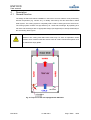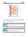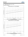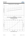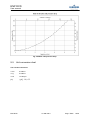
1
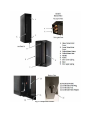
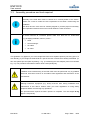
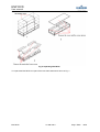
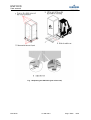
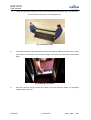
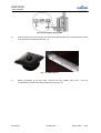
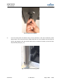
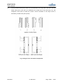
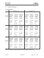
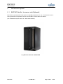
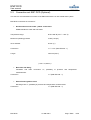
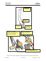
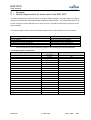
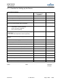
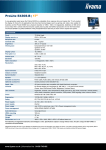
User manual
Emerson Network Power DCD
Knürr DCD
Liebert DCD
Rear door heat exchanger up to 35kW
for mounting on a rack
Date / Datum
24/11/14
Issue / Ausgabe
01.998.355.0.-
Author / Erstellt
Martin BLASS
Reviewed / Geprüft
Heiko EBERMANN
Unit code and component location
1
D
2
C
Model number - part 1/2
3 4 5 6 7 8 9
D 3 5 A 6 3 3
10
0
11
0
12
0
1. - 3. Product identification
DCD = ENP DCD
4. - 5. Nominal cooling capacity
35 = 35 kW
6. Rack height
A = 2000 mm (78 – 6/8”)
B = 2100 mm (82 – 5/8”)
13
0
14
0
Model details
15 16 17 18
0
1
0
0
19
0
20
0
0 = No options (Not available at the
moment)
11. – 15. Not in use
0 = No options (Not available at the
moment)
16. Color
1 = RAL 7035 (light grey)
M = modification (custom – SFA only)
G = RAL 7021 (dark grey)
6 = 600 mm (23 – 5/8”)
22
X
10. Options
C = 2200 mm (86 – 5/8”)
7. Rack width
21
S
2 = non standard color (SFA)
17. – 20. Not in use
7 = 700 mm (27 – 4/8”)
0 = No options (Not available at the
8 = 800 mm (31 – 4/8”)
moment)
M = modification (custom – SFA only)
8. Rack depth
21. Packaging
P = Land freight – short distance
E = 1000 mm (39 – 3/8”)
(pallet, shrink wrap, cardboard
F = 1100 mm (43 – 3/8”)
protection)
G = 1200 mm (47 – 2/8”)
S = Seaworthy (air freight) – long
rd
3 = 3 part rack adaptor
0 = no rack
M = modification (custom – SFA only)
9. Chilled water connection – hinge position
1 = top – left
2 = top – right
3= bottom – left
4 = bottom – right
distance (wooden crate)
22. SFA – special features
X = SFAs included
A = no SFAs
23. – 25. Order identifier
Part 2/2
23 24 25
0
0
1
Fig. 1 Component location
ENP DCD
User manual
Contents
Unit code and component location .............................................................................................................. 3
Contents .......................................................................................................................................................... 5
List of figures .................................................................................................................................................. 6
List of tables ................................................................................................................................................... 7
0
Abstract .............................................................................................................................................. 8
1
Safety .................................................................................................................................................. 8
1.1
Symbols ............................................................................................................................................... 8
1.2
Safety notice ........................................................................................................................................ 9
2
Storage and transportation ............................................................................................................ 11
3
Installation and commissioning..................................................................................................... 12
3.1
Preparations for installation ............................................................................................................... 12
3.2
Piping and connection methods ........................................................................................................ 13
3.3
Assembly procedure and tools required ............................................................................................ 16
3.3
Chilled water connection ................................................................................................................... 30
3.4
Filling with water ................................................................................................................................ 31
3.5
Housing integrity ................................................................................................................................ 31
3.6
Application conditions ........................................................................................................................ 32
4
Description ....................................................................................................................................... 33
4.1
General function ................................................................................................................................ 33
4.2
Cooling principle ................................................................................................................................ 34
4.3
Submittal drawings ............................................................................................................................ 35
5
Variants and options ....................................................................................................................... 40
5.1
ENP DCD built in the server rack (Option – digit 8) .......................................................................... 40
5.2
Connection set ENP DCD (Separate product) .................................................................................. 41
6
Maintenance and repairs ................................................................................................................ 43
7
Disassembly and disposal ............................................................................................................. 44
8
Customer service ............................................................................................................................ 44
9
Annexes ............................................................................................................................................ 45
9.1
Quality Requirements for water used in the ENP DCD ..................................................................... 45
9.2 Checklist for Setting up the Device ..................................................................................................... 46
9.3
Commissioning Protocol .................................................................................................................... 47
9.4
ENP DCD – performance charts ....................................................................................................... 51
9.5
Unit conversion chart ......................................................................................................................... 53
ENP DCD
01.998.355.0
Page / Seite
5/54
ENP DCD
User manual
List of figures
Fig. 1 Component location...................................................................................................................... 4
Fig. 2 Ring piping .................................................................................................................................. 13
Fig. 3 Tichelmann ring piping ............................................................................................................... 13
Fig. 4 Non - interlaced piping................................................................................................................ 14
Fig. 5 Floor cut outs - unit itself ............................................................................................................ 14
Fig. 6 Floor cut outs - unit with aluminium frame.................................................................................. 15
Fig. 7 Unpacking ENP DCD ................................................................................................................. 18
Fig. 8 Unpacking the ENP DCD (part of the rack) ................................................................................ 19
Fig. 9 Lifting the frame .......................................................................................................................... 20
Fig. 10 Marking the position ................................................................................................................. 20
Fig. 11 Inserting the spring nuts ........................................................................................................... 21
Fig. 12 Diamond nuts .......................................................................................................................... 21
Fig. 13 Hose piece adaptor .................................................................................................................. 22
Fig. 14 Position of the sealing foam ..................................................................................................... 22
Fig. 15 Tightening the screws .............................................................................................................. 23
Fig. 16 Installing the door ..................................................................................................................... 24
Fig. 17 Flexible piping........................................................................................................................... 25
Fig. 18 Inserting sealing rings .............................................................................................................. 25
Fig. 19 Tightening the union nuts ......................................................................................................... 26
Fig. 20 Piping connected ...................................................................................................................... 26
Fig. 21 Hinge covers orientation and position ...................................................................................... 27
Fig. 22 Outmost swivel joint covers connection points ......................................................................... 28
Fig. 23 Attaching the swivel joint covers .............................................................................................. 28
Fig. 24 Inside swivel joint covers .......................................................................................................... 29
Fig. 25 Attaching the grounding wire .................................................................................................... 29
Fig. 26 Chilled water connection .......................................................................................................... 30
Fig. 27 Bleeding point ........................................................................................................................... 31
Fig. 28 Top view of the rack equipped with ENP DCD ......................................................................... 33
Fig. 29 Side view of the rack equipped with ENP DCD ........................................................................ 34
Fig. 30 Submittal drawings – ENP DCD (right hinges) ......................................................................... 36
Fig. 31 Submittal drawings – ENP DCD (left hinges) ........................................................................... 37
Fig. 32 Aluminium frame submittal drawing ......................................................................................... 38
Fig. 33 Server rack with the ENP DCD ................................................................................................ 40
Fig. 34 Connection set.......................................................................................................................... 42
Fig. 35 Connection set - detail .............................................................................................................. 42
Fig. 36 Performance chart 1 ................................................................................................................. 51
Fig. 37 Performance chart 2 ................................................................................................................. 51
Fig. 38 Performance chart 3 ................................................................................................................. 52
Fig. 39 Air side pressure drop .............................................................................................................. 52
Fig. 40 Water side pressure drop ......................................................................................................... 53
ENP DCD
01.998.355.0
Page / Seite
6/54
ENP DCD
User manual
List of tables
Tab. 1 List of tools required .................................................................................................................. 17
Tab. 2 Packaging list ............................................................................................................................ 17
Tab. 3 Operation conditions ................................................................................................................. 32
Tab. 4 Unit dimensions ......................................................................................................................... 35
Tab. 5 Aluminium frame dimensions .................................................................................................... 38
Tab. 6 Technical specifications ............................................................................................................ 39
Tab. 7 Hydrological requirements ........................................................................................................ 45
Tab. 8 Set up checklist ......................................................................................................................... 46
Tab. 9 Unit conversion.......................................................................................................................... 53
ENP DCD
01.998.355.0
Page / Seite
7/54
ENP DCD
User manual
0
Abstract
ENP DCD is an air - water heat exchanger that is integrated into the rear door of a server rack. The
heat exchanger is suitable for absorbing heat loads from server racks of up to 35 kW. It can be
configured in such way that no heat is released to the installation area.
Cooling effect occurs when the server exhaust air passes through the heat exchanger in the rear
section of the server rack. The cooling air is moved through the heat exchanger only by the server
fans. ENP DCD thereby supports the cold room concept in which is the warm exhaust air from servers
always led to a cooling device where its temperature is reduced to the temperature level of the server
supply air. The supply air for chilled water system flows freely through the installation area.
1
Safety
1.1
Symbols
Attention! Danger spot! Safety notice!
Caution! Hot surface.
Attention! Refers to possible damage to the device.
Note! Marks possible hazards for the environment.
Important note, information.
ENP DCD
01.998.355.0
Page / Seite
8/54
ENP DCD
User manual
1.2
Safety notice
Our engineers can give you comprehensive advice in assembling the ENP DCD.
Extensive material, functional and quality testing guaranty high benefit and a long
lifecycle. Nonetheless, such devices may cause hazards if improperly handled by
untrained personnel and if used for purposes they are not intended for.
Carefully read this assembly and operational manual prior to assembling and
commissioning the ENP DCD.
Hazard by works on the device carried out by non-experts. Maintenance and
cleaning operations are only permitted to be performed by trained personnel. In order
to keep the device in operationally safe condition and to grant its long lifecycle,
maintenance and cleaning intervals must be fulfilled by all means.
Operate the ENP DCD only in accordance with its specified purpose, within its limits
of capacity and approved operating means.
When performing any works on and with the device, please mind:
•
Any respectively applicable regulations
(e.g. VDE regulations or other nationally applicable guidelines)
•
Any applicable accident prevention regulations (BGV)
•
Any respective provisions
•
Any applicable environment protection acts
Operate the device only in its proper condition. In the event of functional
disturbances or deficiencies, the device must immediately be taken out of operation
and the operator’s responsible person must be informed of its state. The device must
only be taken into operation again after the flawless function of the device has been
restored.
ENP DCD
01.998.355.0
Page / Seite
9/54
ENP DCD
User manual
Caution! Hot surface! Defect fans, power supply units or control boards may have run
hot. Allow them to cool down before commencing any operations.
ENP DCD
01.998.355.0
Page / Seite
10/54
ENP DCD
User manual
2
Storage and transportation
•
Keep the device in its original packaging, protected from the weather and in dry conditions
•
Protect the working parts from dirt (e.g. sand, rain, dust, etc.)
•
Store at temperatures between -30 °C and +50 °C (-22 °F and +122 °F)
•
Chilled water circuit must be empty during storage (risk of frost damage)
•
After long period of storage (1 year +) inspect functionality of water – bearing hinges
•
Remove all the packaging before commencing operation of the device
•
Chilled water connections are not to be used as a transport handles
•
When transporting always make sure the device is properly fastened and secured against
slipping
Dry net weight +/- 5% kg (lb)
Width
DCD
600 mm
700 mm
~ 95 kg / ~ 210 lb
800 mm
Land freight packaging
+40 kg / +88 lb
Seaworthy packaging
+125 kg / +276 lb
Tab. 1 Unit weight
ENP DCD
01.998.355.0
Page / Seite
11/54
ENP DCD
User manual
3
Installation and commissioning
3.1
Preparations for installation
Before installing the device it is crucial You check each of the following points.
These checks will ensure safe and trouble free operation of ENP DCD. Perform
these tests with great care.
•
Check the device for shipping damage
Packaging may not appear to have been damaged; however, it is necessary to inspect the
device before proceeding to installation. Ignoring this advice may at worst lead to a functional
failure. (When returning the device because of the shipping damage – If the device is not
being sent in its original, packaging please make sure the distance between the device and
the new packaging is at least 30 mm ~ 1.18 in)
•
Qualified installation
Please find the checklist enclosed in the annex to help with installation. Commissioning can
also be done by specialised company. In this case please find the commissioning protocol
enclosed in the annex.
•
Room Preparation
The room should be well-insulated and must have a sealed vapour barrier. The vapour barrier
in the ceiling and walls can be a polyethylene film. Paint on concrete walls and floors should
contain either rubber or plastic. The vapour barrier is the single most important requirement
for maintaining environmental control in the conditioned space.
ENP DCD
01.998.355.0
Page / Seite
12/54
ENP DCD
User manual
3.2
Piping and connection methods
If possible when using a chilled water distribution unit such as the Knürr CoolTrans or the Liebert
XDPW, connect the ENP DCD in an “ring” configuration (see Fig. 1) or Tichelmann ring (Fig. 2) In this
system the pressure drop for each of the units is approximately the same which results in even
cooling performance.
Fig. 1 Ring piping
Fig. 2 Tichelmann ring piping
However, if it is not possible, connect the ENP DCD units in a non-interlaced configuration as seen in
Fig. 3.
ENP DCD
01.998.355.0
Page / Seite
13/54
ENP DCD
User manual
Fig. 3 Non - interlaced piping
It is recommended to add a set of 2 ball valves to each unit (supply and return pipe) to allow the unit
to be disconnected from the system for repairs and maintenance without taking the whole system
down.
Fig. 4 Floor cut outs - unit itself
ENP DCD
01.998.355.0
Page / Seite
14/54
ENP DCD
User manual
Fig. 5 Floor cut outs - unit with aluminium frame
ENP DCD
01.998.355.0
Page / Seite
15/54
ENP DCD
User manual
3.3
Assembly procedure and tools required
Assembly of the ENP DCD must be carried out in vertical position of the device.
Please use a level to make sure this requirement is met when commencing the
installation.
ENP DCD and the rack must be vertically aligned to provide proper functionality.
Strict separation between the hot and cold air within the case must exist.
To ensure suficient air circulation please make sure there are no obstructions
(e.g. packaging materials, tools etc.) left in…
•
Grids
•
Heat exchanger
•
Air intake
•
Air outlet
This guideline only applies if you have bought ENP DCD as a separate product (not being part of a
rack already). If you bought the ENP DCD as a part of the rack it would come already assembled. (In
this case please proceed (after unpacking – Fig. 7) to attaching the hose adaptor piece from beneath
Fig. 12). The procedure described is valid for Knürr racks (DCM) only.
Installation and commissioning of the ENP DCD must be performed only by qualified
personnel. All actions must be in accordance with regulations and instructions of the
manufacturer.
Warning! Protective equipment (e.g. boots) must be worn during installation and
maintenance of this device. Please check your local regulations on using safety
equipment before commencing any operations.
This procedure also requires at least 2 persons to complete. The unit weighs 95 kg
(approx. 210 pounds)
ENP DCD
01.998.355.0
Page / Seite
16/54
ENP DCD
User manual
Tab. 2 List of tools required
Socket hexagonal screw driver - 8 mm (5/16”)(for M5 screws)
Open – jaw wrench 41 mm (1-5/8”)
Open – jaw wrench 36 mm (1-7/16”)
Phillips screw driver PH3
Utility knife
Forklift, pallet jack (or similar device)
Tab. 3 Packaging list
Component description
ST mounting bracket for miracel+
ST mounting bracket for miracel+
ST cover swivel-joint fixed compo
ST cover swivel-joint fixed compo
ST cover swivel-joint door compon
ST cover swivel-joint door compon
ST foam UL94-HF1 20mmx32mm
ST Condensate Drain-Set
individual components
1
1
7
6
8
ST Wire - Grounding 250/6 RA5xRA5
ST EARTH WIRE 200/6 RA5xFH6,3pl
ST M5 TENSILOCK NUT
ST M5 MOUNTING NUT-MIR.EXTRUSION
ST washer M5
bag nr.1
30
ST Star Screw M5x10
bag nr. 2
16
ST Spring Nut M5 broad
bag nr. 3
8
ST DIN965 M6x16
bag nr. 4
Quantity
1
1
1
1
1
1
1
1
To unpack ENP DCD (shipped separately) follow the instructions shown in Fig. 6.
ENP DCD
01.998.355.0
Page / Seite
17/54
ENP DCD
User manual
Fig. 6 Unpacking ENP DCD
To unpack the ENP DCD as a part of the rack follow instructions show in Fig. 7.
ENP DCD
01.998.355.0
Page / Seite
18/54
ENP DCD
User manual
Fig. 7 Unpacking the ENP DCD (part of the rack)
ENP DCD
01.998.355.0
Page / Seite
19/54
ENP DCD
User manual
1
After removing the packaging, first lift the ENP DCD frame of the pallet (Fig. 8). At this point
the door and the frame are not fixed together yet.
Fig. 8 Lifting the frame
2
Then align the frame of the ENP DCD to server rack properly. Mark the positions of the frame
holes (there are 16 holes) on the aluminium profile of the server rack and put the frame aside
again.
Fig. 9 Marking the position
3
After that, insert the spring nuts into the groove of the rack aluminium profile in to previously
marked position (Fig. 10).
ENP DCD
01.998.355.0
Page / Seite
20/54
ENP DCD
User manual
Fig. 10 Inserting the spring nuts
4
Insert 3 diamond nuts into the grove of each horizontal member of the rack aluminium profile
in the previously marked position (Fig. 11).
Fig. 11 Diamond nuts
5
Before proceeding to the next step, connect the hose adaptor piece (5/8 “) into the
condensate tray (remove the white plastic plug first) (Fig. 12).
ENP DCD
01.998.355.0
Page / Seite
21/54
ENP DCD
User manual
Fig. 12 Hose piece adaptor
6
In the next step place the adhesive strip of foam (included) on the rack’s aluminium profile
(hinge side) in such way that when the ENP DCD frame is in the position the foam strip will
seal the gap between rack and the ENP DCD frame (It might be necessary to trim the foam
strip with utility knife) (Fig. 13).
Fig. 13 Position of the sealing foam
ENP DCD
01.998.355.0
Page / Seite
22/54
ENP DCD
User manual
7
Now you can start attaching the frame of ENP DCD to the rack using the socket screw driver
(Fig. 14). Tighten the screws all around the perimeter of the frame, first lightly and then to
3 Nm (2 pound foot). This is the only way to prevent the frame from twisting and to ensure the
parts fit properly.
Fig. 14 Tightening the screws
Make sure there is no twist in the frame before proceeding. The next step in installation is to attach
the heat exchanger door to the frame.
Attention! Risk of injury! The heat exchanger door is very heavy (95 kg, approx 210
pounds). At least 2 persons are required for manipulation with the door.
8
Carefully align the door to the frame and insert the door into the frame (Fig. 15).
ENP DCD
01.998.355.0
Page / Seite
23/54
ENP DCD
User manual
Fig. 15 Installing the door
9
Hinges are already attached to the door. Fasten them to the frame of the ENP DCD using the
Phillips screw driver. Then check if the door moves freely all the way. If you notice any
irregularities or roughness in the movement of the door, check for obstructions or loosen the
screws of the hinges and tighten them again. (The rough movement might have occurred
because of the twist in the hinges).
10
Pull the flexible piping slightly to elongate. This allows the piping enough length to connect
the union nuts.
ENP DCD
01.998.355.0
Page / Seite
24/54
ENP DCD
User manual
Fig. 16 Flexible piping
11
Before connecting the heat exchanger (in the door) with the pipe work in the frame of the ENP
DCD, put sealing rings in this connection (Fig. 17). Use two wrenches when tightening the
union nuts to reduce the stress on the pipes (Fig. 18). Torque value for this connection is 85
Nm (64 foot/pound).
Fig. 17 Inserting sealing rings
ENP DCD
01.998.355.0
Page / Seite
25/54
ENP DCD
User manual
Fig. 18 Tightening the union nuts
Fig. 19 Piping connected
12
Check again if the door is moving freely at this point. If so you can attach the swivel joint
covers.
ENP DCD
01.998.355.0
Page / Seite
26/54
ENP DCD
User manual
13
The two outmost swivel joint covers are to be attached to the hinge side of the door. The two
inside swivel joint covers are to be attached to the hinge side of the frame (Fig. 21). Use
hexagonal screw driver to fasten the screws. Correct orientation of the hinge covers is
indicated by slotted holes (See picture).
Fig. 20 Hinge covers orientation and position
ENP DCD
01.998.355.0
Page / Seite
27/54
ENP DCD
User manual
Fig. 21 Outmost swivel joint covers connection points
Fig. 22 Attaching the swivel joint covers
14
Locate the inside swivel joint cover connection points. The two inside swivel joint covers are
to be attached to the hinge side of the frame. Correct orientation of the hinge covers is
indicated by a sticker on the covers themselves. Use hexagonal screw driver to fasten the
screws (Fig. 22)
ENP DCD
01.998.355.0
Page / Seite
28/54
ENP DCD
User manual
Door
Door
Fig. 23 Inside swivel joint covers
15
In the last step connect the grounding wire of the door to the frame of the ENP DCD (Fig. 24).
Fig. 24 Attaching the grounding wire
Check if this connection is alright (e.g. by using “diode” or continuity test on a multimeter).
16
Check functionality of the door lock. ENP DCD is equipped with DIRAK 1333 lock. It is a ½”
inch cylinder lock. Keys are provided.
ENP DCD
01.998.355.0
Page / Seite
29/54
ENP DCD
User manual
3.3
Chilled water connection
Check the chilled water system for leaks visually before commissioning. Please
check the chilled water pipe connection to the heat exchanger regularly. Tighten
this connection if necessary.
When setting up the heat exchanger for the first time please inspect the mechanical
condition of the chilled water supply and connection thoroughly.
(Note: Using the optional connection set (chapter 5.2) improves the ventilation and enables chilled
water flow monitoring and regulation)
There is a risk of frost damage to the device during longer stops (e.g. storing etc.)
Make sure the heat exchanger and the supply pipes are free of any water (use
compressed air if necessary) and remove all the vents and the screws before
storing.
The coil and piping can be damaged due to thermal expansion of the cooling fluid
with no means of expansion (e.g. closing the ball valves on both the supply and the
return pipes). Always allow for thermal expansion either by leaving at least one of
the valves open or by opening the bleeding valve on the door.
Supply and return pipes are marked by label on the unit itself. Torque value for this connection is
85 Nm (64 foot/pound).
Fig. 25 Chilled water connection
ENP DCD
01.998.355.0
Page / Seite
30/54
ENP DCD
User manual
For water supply from the bottom left or top right of the position, the supply water
connection is the outward pipe. The return water connection is then the position
towards the rack.
With water connection from top-left or bottom right, the water supply connection is
the pipe towards the rack. The return pipe then has the position toward the outside.
3.4
Filling with water
If using a chilled water distribution unit such as the Knürr CoolTrans or Liebert XDPW, refer to its user
manual for instructions on filling the ENP DCD and starting the system. Heat exchanger fluid
volume is approximately 12 liters (3.17 US Gal.)
Bleeding the air off the system
1. Find the bleeding valve. This valve is located on the upper door piping (seeFig. 26 ).
2. Manually depress the pin to open the valve.
3. Keep the air bleed valve open until the eater coming out has no bubbles.
Fig. 26 Bleeding point
3.5
Housing integrity
To provide optimal cooling function following requirements must be met
•
Strict separation between the hot and cold air must exist within the rack
•
All the bushings (cable lines, piping etc) must be sealed to prevent any leakages
ENP DCD
01.998.355.0
Page / Seite
31/54
ENP DCD
User manual
3.6
Application conditions
Appropriate use
The device is a rear door heat exchanger for a server cabinet with integrated chilled
water piping. The server fans themselves remove the heat from the racks to protect
the temperature sensitive components in the rack. The waste heat from inside of the
rack is transferred via the chilled water circuit to the outside and passed to the onsite chilled water system.
For reliable function of the ENP DCD, chilled water must be available in an
appropriate amount, at the appropriate temperature and pressure. The water quality
must be in accordance with VGB-R 455 P. (see Annex)
Tab. 4 Operation conditions
Operating ambient temperature
10 °C ÷ 35°C (other temperatures on request)
50 °F – 95 °F
Maximum absolute air humidity on site
8
Chilled water temperature intake
12 °C, 53.6 °F (other temperatures on request)
Chilled water temperature outlet
18 °C, 64.4 °F (other temperatures on request)
Water temperature difference
6 K, 10.8 °F
Use of antifreeze
Not recommended (on request)
Chilled water connection
Rack – rear side (top or bottom connection)
1” female threaded (DIN ISO 228 - 1)
Condensate tray drain connection
Rack – rear side
Maximum operating pressure
10 bar (145 psi)
g ⋅ kg −1
The cold water supply temperature should be higher than the dew point temperature
of the installation space. ENP DCD is designed only for sensible cooling;
dehumidification of the room by means of ENP DCD should be avoided. The built in condensate tray with condensate drain is designed only for a short-term
condensation.
ENP DCD
01.998.355.0
Page / Seite
32/54
ENP DCD
User manual
4
4.1
Description
General function
The design of ENP DCD allows installation in the back of a server cabinet. Heat produced by
internal components (e.g. servers etc.), is reliably removed by the door with built-in chilled
water system. The cooling system is completely safe so that no water get into the server area.
The cooling system consists of a high efficiency air - water heat exchanger. By operating as a
rear door heat exchanger with an appropriate design (see Appendix) no heat (thermal load) in
the surrounding area is given.
Attention! The cooling with ENP DCD works only if a strict air separation exists
between server cold air intake and server warm air outlet. Unused rack spaces must
be sealed with empty plates.
Fig. 27 Top view of the rack equipped with ENP DCD
ENP DCD
01.998.355.0
Page / Seite
33/54
ENP DCD
User manual
4.2
Cooling principle
Fig. 28 Side view of the rack equipped with ENP DCD
Air heated by the server (e.g. 40 °C, 104 °F), is forced through the special air – water heat exchanger.
In the heat exchanger the air is cooled down to e.g. 20 °C – 25 °C (68 °F – 77 °F). The server fans
force the cooling air through the heat exchanger of ENP DCD. The “pressure drop - flow rate”
dependency curve is shown in the Appendix (9.4).
Prior to using ENP DCD the system and the servers must be checked whether they
match hydraulically. In particular, the server fans must be able to generate sufficient
pressure to drive the air through the ENP DCD.
The chilled water is provided by chilled water onsite distribution.
In case of chilled water supply system failure the cooling is provided either by
adjacent ENP DCDs and / or the installation room cooling system. In this case the
server waste heat is released into the installation room.
ENP DCD
01.998.355.0
Page / Seite
34/54
ENP DCD
User manual
4.3
Submittal drawings
Tab. 5 Unit dimensions
2000 mm (78-3/4")
2200 mm (85-3/4")
B=1954mm
C=600mm
D=493mm
B=2176mm
C=600mm
D=493mm
600 mm
F=322mm
G=151mm
H=120mm
F=322mm
G=151mm
H=120mm
(23-5/8")
I=45mm
J=40.7mm
K=24mm
I=45mm
J=40.7mm
K=24mm
L=52mm
M=73mm
N=25mm
L=52mm
M=73mm
N=25mm
B=77-7/8“
C=23-5/8“
D=19-3/8“
B=85-3/4“ “
C=23-5/8“
D=19-3/8“
F=12-5/8“
G=6”
H=4-6/8”
F=12-5/8“
G=6”
H=4-6/8”
I=1-6/8”
J=1-5/8”
K=1”
I=1-6/8”
J=1-5/8”
K=1”
L=2”
M=2-7/8”
N=1”
L=2”
M=2-7/8”
N=1”
B=1954mm
C=700mm
D=593mm
B=2176mm
C=700mm
D=593mm
F=372mm
G=151mm
H=120mm
F=372mm
G=151mm
H=120mm
700 mm
I=45mm
J=40.7mm
K=24mm
I=45mm
J=40.7mm
K=24mm
(27-1/2")
L=52mm
M=73mm
N=25mm
L=52mm
M=73mm
N=25mm
B=77-7/8“
C=27-1/2“
D=23-3/8“
B=85-3/4“
C=27-1/2“
D=23-3/8“
F=14-5/8“
G=6”
H=4-6/8”
F=14-5/8“
G=6”
H=4-6/8”
I=1-6/8”
J=1-5/8”
K=1”
I=1-6/8”
J=1-5/8”
K=1”
L=2”
M=2-7/8”
N=1”
L=2”
M=2-7/8”
N=1”
B=1954mm
C=800mm
D=693mm
B=2176mm
C=800mm
D=693mm
F=422mm
G=151mm
H=120mm
F=422mm
G=151mm
H=120mm
800 mm
I=45mm
J=40.7mm
K=24mm
I=45mm
J=40.7mm
K=24mm
(31-1/2")
L=52mm
M=73mm
N=25mm
L=52mm
M=73mm
N=25mm
B=77-7/8“
C=31-1/2“
D=27-1/4“
B=85-3/4“
C=31-1/2“
D=27-1/4“
F=16-5/8“
G=6”
H=4-6/8”
F=16-5/8“
G=6”
H=4-6/8”
I=1-6/8”
J=1-5/8”
K=1”
I=1-6/8”
J=1-5/8”
K=1”
L=2”
M=2-7/8”
N=1”
L=2”
M=2-7/8”
N=1”
Please find the reference to the dimensions stated in this table in the Fig. 29 and Fig. 30.
ENP DCD
01.998.355.0
Page / Seite
35/54
ENP DCD
User manual
Fig. 29 Submittal drawings – ENP DCD (right hinges)
(1 mm = 0,0394 in.)
ENP DCD
01.998.355.0
Page / Seite
36/54
ENP DCD
User manual
Fig. 30 Submittal drawings – ENP DCD (left hinges)
(1 mm = 0,0394 in.)
ENP DCD
01.998.355.0
Page / Seite
37/54
ENP DCD
User manual
Fig. 31 Aluminium frame submittal drawing
(1 mm = 0,0394 in.)
Tab. 6 Aluminium frame dimensions
[mm]
[in]
B=592mm
C=1954mm
D=65.9mm
E=53.5mm
B=23-2/8"
C=76-7/8"
D=2-5/8"
E=2-1/8"
F=49.5mm
G=48.7mm
H=37.7mm
I=22.6mm
F=2"
G=1-7/8"
H=1-1/2"
I=7/8"
J=20.5mm
K=18.6mm
L=15mm
M=20.6mm
J=6/8"
K=6/8"
L=5/8"
M=6/8"
N=7.9mm
ENP DCD
N=2/8"
01.998.355.0
Page / Seite
38/54
ENP DCD
User manual
Tab. 7 Technical specifications
Cooling air side
Housing material
Steel plate (powder coated)
Operating ambient temperature
10 °C ÷ 35°C (50 °F – 95 °F) (other
temperatures on request)
Maximum absolute air humidity on site
8
Air outlet temperature
18 °C ÷ 27 °C (64.4 °F – 80.6 °F)
g ⋅ kg −1
(in accordance with ASHARE)
Air temperature difference IN - OUT
15 K ÷ 20 K
Chilled water side
Cooling performance
35 kW
Chilled water temperature inlet
12 °C ÷ 18 °C (53.6 °F – 64.4 °F)(other
temperatures on request)
Chilled water temperature outlet
18 °C ÷ 24 °C (64.4 °F – 75.2 °F)(other
temperatures on request)
Maximum operating pressure
10 bar (145 psi)
Pipe connection IN / OUT
1” F (on the frame) (DIN ISO 228 - 1)
ENP DCD
01.998.355.0
Page / Seite
39/54
ENP DCD
User manual
5
Variants and options
5.1
ENP DCD built in the server rack (Optional)
ENP DCD is typically delivered as a part of a specially prepared server rack. The DCM server rack
offers guaranteed air separation between the hot and the cold air within the cabinet.
(For a detailed description check the “Knürr DCM” manual)
Fig. 32 Server rack with the ENP DCD
ENP DCD
01.998.355.0
Page / Seite
40/54
ENP DCD
User manual
5.2
Connection set ENP DCD (Optional)
This set is for recommended connection of the ENP DCD with the on site chilled water system.
ENP DCD connection set consists of
•
Reinforced hose with nickel - plated connections
EPDM resistant to water and anti freeze
Temperature range
0 °C ÷ 110 °C (32 °F – 230 °F)
Maximum operating pressure
10 bar (145 psi)
Inner diameter
25 mm (1”)
Connection
1” F / 1” M (DIN ISO 228 - 1)
Length
1500 mm (59,1”)
(1 mm = 0,0394 in.)
•
Ball valve with fitting
Ventilation
and
drain
connection
¾”;
possibility
of
pressure
and
temperature
measurements.
Connection
•
1” F (DIN ISO 228 - 1)
Shut off and regulation valve
Discharge vent ¾”; possibility of pressure and temperature measurements.
Connection
ENP DCD
1” F (DIN ISO 228 - 1)
01.998.355.0
Page / Seite
41/54
ENP DCD
User manual
Connection to
the ENP DCD
Chilled water
outlet (hot)
Chilled water
intake (cold)
Connection to
the on site
chilled system
Fig. 33 Connection set
Ball valve - 1“connection
Ventilation and drain connections
(Pressure and temperature
measurements possible)
Bleeding and ventilation point
(Flow rate measurements
possible)
Shut off and regulation valve
(Flow rate measurements possible)
Fig. 34 Connection set - detail
(Note: All parts of the set are supplied as individual parts and are connected by the customer)
ENP DCD
01.998.355.0
Page / Seite
42/54
ENP DCD
User manual
6
Maintenance and repairs
All maintenance and repair jobs are to be performed by qualified personnel only. All
actions must be in accordance with regulations and instructions of the manufacturer.
For maintenance and repair jobs use only the tools and spare parts approved by
manufacturer of the device.
Before commencing any work on the chilled water system let the system drain.
General maintenance actions to be carried out
•
Check the heat exchanger pollution (dust etc.)
•
Check functionality of the valves
•
Check the chilled water system for leaks visually
Please note that dirt (dust layer etc.) on the heat exchanger reduces the performance
of the device (increased pressure loss, worse heat transfer). Vacuum cleaner, soft
brush, or compressed air can be used to clean the fins of the heat exchanger.
ENP DCD
01.998.355.0
Page / Seite
43/54
ENP DCD
User manual
7
Disassembly and disposal
Disassembly of the ENP DCD may be performed by qualified personnel only.
Shut down the chilled water system before disassembly and prevent it from
restarting.
Dispose all the components and parts in accordance with local waste management
and regulations. We recommend a recycling company.
All components consist of:
8
•
Aluminium, steel, brass, copper
•
Marked plastic components
Customer service
All Knürr products are subject to continuous quality control and comply with applicable regulations.
For any questions you have related to our products, please contact the manufacturer of your system
directly:
Knürr GmbH
Glashüttenstraße 1
01623 Lommatzsch
Tel.: +49 (0) 800 000 6295
Email: [email protected]
ENP DCD
01.998.355.0
Page / Seite
44/54
ENP DCD
User manual
9
9.1
Annexes
Quality Requirements for water used in the ENP DCD
In order to safeguard the maximum lifetime of air/water heat exchangers, the water applied for chilling
purposes must meet the VGB Chilled Water Guidelines (VGB-R 455 P). The chilled water used must
be soft enough to prevent deposits, but it must not be too soft which would lead to corrosion of the
heat exchanger.
The following table contains the most important impurities and counter-measures for their removal:
Water impurity
Mechanical impurity (dp < 0.3 mm)
Excess hardness
Moderate level of mechanical impurities and hardeners
Moderate level of chemical impurities
Biological impurities (bacteria and algae)
Method for removal
Filter the water
Soften the water by ion exchange
Add dispersion or stabilizing agents
Add deadening agents and inhibitors
Add biocides
It is recommended to get as closest as possible to the following hydrological parameters:
Tab. 8 Hydrological requirements
Hydrological data
pH values
Carbonate hardness
Free carbon dioxide
Combined carbon dioxide
Aggressive carbon dioxide
Sulphides
Oxygen
Chloride ions
Sulphate ions
Nitrates and nitrites
COB
Ammonia
Iron
Manganese
Conductivity
Solid residue from evaporation
Potassium manganese consumption
Suspended matter
(partial flow cleaning is recommended)
(permanent cleaning)
ENP DCD
(7 ÷ 10,5)
(3 ÷ 8)
(8 ÷ 15)
(8 ÷ 15)
0
< 10
< 50
< 250
< 10
<7
<5
<5
< 0.2
< 0.2
< 30
< 500
< 25
<3
(3 ÷ 15)
> 15
01.998.355.0
°dH
mg/dm3
mg/dm3
mg/dm3
mg/dm3
mg/dm3
mg/dm3
mg/dm3
mg/dm3
mg/dm3
mg/dm3
mg/dm3
mg/dm3
µS/cm
mg/dm3
mg/dm3
mg/dm3
mg/dm3
mg/dm3
Page / Seite
45/54
ENP DCD
User manual
9.2 Checklist for Setting up the Device
Tab. 9 Set up checklist
Performed checks
Done
Remarks
(to be signed upon
completion)
Check device for damage upon receipt.
Check the ground for being horizontal.
Check bearing capacity of ground.
Add-on and align, connect to server cabinet, position
feet of the rack and adjust them horizontally
Cables connected with server cabinet:
- Temperature sensors (optional)
- Server shut-down (optional)
- Door contact (optional)
Unit connected with set of external valves (optional):
- Valve drive
- Flow meter with temperature sensors (optional)
Optional automatic door opening adjusted at server
cabinet
No remainders of packaging inside ENP DCD
All assembly tools removed
Bushings into the device proper and air-tight
Chilled water connection leak-proof / pressure-tested
Chilled water system de - aerated
Volume flow of chilled water adjusted
Condensed water line unobstructed
Smell trap of chilled water system functional
Condensate tray connected to condensed water line
All front panels closed (air ducts technically separated)
.............................................
Place:
ENP DCD
........................................
Date:
01.998.355.0
....................
Signature
of Tester
Page / Seite
46/54
ENP DCD
User manual
9.3
Commissioning Protocol
ENP DCD Commissioning Protocol
1
General Details
1.1
Customer/Site of installation
Customer’s name:
………………………..
Customer’s address:
………………………..
………………………..
………………………..
1.2
Contact partner:
………………………..
Phone number:
………………………..
Site of installation / room number:
..................................
Humidity at site of installation:
................................... % rel. humidity
Ambient temperature
................................... ° C
Configuration
Cabinet type:
ENP DCD 35 kW
□
Commissioning number (if applicable):
...................................
Serial number:
...................................
Special remarks:
.........................................................................................................................................
.........................................................................................................................................
.........................................................................................................................................
2
State Check
2.1
General State
Customer’s proof of bearing capacity of ground / transport ways
Check of alignment
Transport damage to housing:
ENP DCD
yes
01.998.355.0
□
□
□
no
Page / Seite
□
47/54
ENP DCD
User manual
Remarks
.........................................................................................................................................
.........................................................................................................................................
.........................................................................................................................................
2.2
Residual packaging removed:
yes
□
no
□
Assembly tools removed:
yes
□
no
□
Air ducts checked:
(Server cabinet front plates closed… )
yes
□
no
□
□
without anti-freeze
□
Chilled Water System within the Facility
Chilled water:
with anti-freeze
ENP DCD
Connected to:
CTU
Circuit in building, direct
□
□
cold water system, direct
Chilled water temperature
(primary):
Feed: .........
°C
Return: .........
°C
Chilled water pressure
Feed: .........
bar
Return: .........
bar
□
Connection:
with Knürr connection set
set of external valves
□
□
Customer’s hydraulic plant OK
(visual check):
Remarks:
ENP DCD
□
yes
no
□
……………………………………………………..
01.998.355.0
Page / Seite
48/54
ENP DCD
User manual
3
3.1
Functional Check
Mechanical Functions
Damage to heat exchanger/
existing
Connections/ lamellas / surface:
none
Remarks:
.........................................................................................................................................
□
□
□
□
□
□
□
□
□
□
□
□
□
□
Front door, closing:
yes
no
Remarks:
.........................................................................................................................................
Rear door, closing:
yes
no
Remarks:
.........................................................................................................................................
no
Pipe duct inlets / cable bushings closed:
yes
Remarks:
.........................................................................................................................................
Condensed water drain open / connected:
yes
no
remarks:
.........................................................................................................................................
Fans run perfectly (bearings OK)
Visual check
yes
no
Remarks:
.........................................................................................................................................
3.2
Thermodynamic Checks
Condensed water forming at heat exchanger
yes
no
Remarks:
.........................................................................................................................................
Chilled water entering heat exchanger:
...............° C
Chilled water leaving heat exchanger:
...............° C
Cabinet temperature in front of heat exchanger:
...............° C
Cabinet temperature behind of heat exchanger:
...............° C
ENP DCD
01.998.355.0
Page / Seite
49/54
ENP DCD
User manual
yes
□
no
□
Pressure of chilled water network tested:
(customer’s protocol available)
yes
□
no
□
Volume flow adjusted:
yes
□
no
Chilled water network bleeded:
external
Water flow:
…………. l / min
external
□
□
□
Remarks:
.........................................................................................................................................
Correctness of above values is hereby confirmed.
Commissioning was performed during on-going operation.
yes
□
no
□
.........................................
Commissioning firm
................................
Date
.............................................
Signature
.........................................
Customer
................................
Date
..............................................
Signature
ENP DCD
01.998.355.0
Page / Seite
50/54
ENP DCD
User manual
9.4
ENP DCD – performance charts
Performance diagrams
Fig. 35 Performance chart 1
Fig. 36 Performance chart 2
ENP DCD
01.998.355.0
Page / Seite
51/54
ENP DCD
User manual
Fig. 37 Performance chart 3
Fig. 38 Air side pressure drop
ENP DCD
01.998.355.0
Page / Seite
52/54
ENP DCD
User manual
Fig. 39 Water side pressure drop
9.5
Unit conversion chart
Tab. 10 Unit conversion
1 mm
0.0394 in
1 kg
2.205 lbs
1 bar
14.504 psi
[°F]
([°C ] ⋅ 1.8) + 32
ENP DCD
01.998.355.0
Page / Seite
53/54
ENP DCD
User manual
ENP DCD
01.998.355.0
Page / Seite
54/54