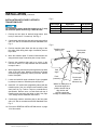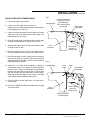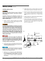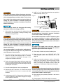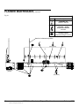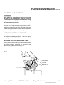
1
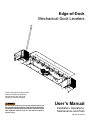
Edge-of-Dock
Mechanical Dock Levelers
This manual applies to Edge-of-Dock
levelers manufactured beginning
December 2010 with the serial
numbers 61000001 and higher.
Do not install, operate or service this product unless you
have read and understand the Safety Practices, Warnings,
Installation and Operating Instructions contained in this
User’s Manual. Failure to do so could result in death or
serious injury.
User’s Manual
Installation, Operations,
Maintenance and Parts
Part No. 6007631H
table of contents
Table of Contents........................................................2
Introduction..................................................................2
Safety Signal Words....................................................2
Safety Practices..........................................................3
Owner's Responsibilities.............................................4
Ramp Lip Grades........................................................5
Installation...................................................................6
Operation Instructions...............................................13
Planned Maintenance................................................16
Parts List...................................................................20
Warranty....................................................................23
Contact Information...................................................24
introduction
Welcome and thank you for choosing this dock leveler.
This User’s Manual contains information that you need to safely install, operate and maintain the dock leveler. It
also contains a complete parts list and information about ordering replacement parts. Please keep and read this
User’s Manual before using your new dock leveler.
safety signal words
You may find safety signal words such as DANGER, WARNING, or CAUTION throughout this User’s Manual.
Their use is explained below:
This is the safety alert symbol. It is used
to alert you to potential personal injury
hazards. Obey all safety messages that
follow this symbol to avoid possible death or injury.
Indicates an imminently hazardous situation which, if
not avoided, will result in death or serious injury.
Indicates a potentially hazardous situation which, if
not avoided may result in minor or moderate injury.
Indicates a potentially hazardous situation which,
if not avoided, could result in death or serious
injury.
Notice is used to address practices not related to
personal injury.
2
6007631H — Mechanical Edge-of-Dock Levelers
©2012 4Front Engineered Solutions, Inc.
February 2012
safety practices
Read these safety practices before installing, operating
or servicing the dock leveler. Failure to follow the safety
practices could result in death or serious injury.
If you do not understand the instructions, ask your supervisor
to explain them to you or contact your local distributor.
Before doing any maintenance or repair on the dock leveler
SECURE WITH THE MAINTENANCE STRUT. See Fig. 20.
operation
Operating range is 5” above to 5” below dock. Effective
working range is 3” above to 3” below dock. Verify with the
manufacturers of all equipment to be used on your specific
edge-of-dock leveler, to ensure that operating equipment
at all specified grades are within safe operation. Do not
operate any equipment that will not safely operate at any of
the grades shown on page 5 at either ramp or lip.
Use of dock leveler is restricted to trained operators. Follow
procedures on placards posted near dock leveler. Call
972-466-0707 or 800-525-2010 for replacement placards,
warning labels or owner’s manual.
Do not use the dock leveler if it looks broken or does not
seem to work right. Tell your supervisor it needs repair right
away.
Visually check that lip is supported by the vehicle bed before
driving on ramp.
Chock vehicle wheels or lock vehicle in place with a
vehicle restraining device, and set brakes before loading or
unloading.
Do not stand in the driveway between the dock leveler and
a backing vehicle.
Move all equipment, material or people off dock leveler, and
store dock leveler at dock level before allowing the vehicle to
move away from the dock.
Do not use a fork truck or other material handling equipment
to lift or lower the ramp.
Never exceed the rated capacity of the dock leveler.
Do not attempt to lift the dock leveler ramp or lip by any
means other than that described in the operating procedures
contained in this manual. If the dock leveler does not operate
correctly when using the operating procedures contained in
this manual, DO NOT USE THE DOCK LEVELER. Contact
your local distributor for maintenance and service repair.
Do not operate the dock leveler with equipment, material or
people on the ramp or lip.
Before chocking wheels or engaging vehicle restraint, dump
air from air ride suspensions and set parking brakes.
Do not operate the dock leveler when anyone is in front of it
unless they are securing the MAINTENANCE STRUT.
Keep feet clear of the underside of ramp and lip when raising
and lowering dock leveler.
Stay clear of the dock leveler when it is moving.
Never exceed 5 mph when driving on leveler.
Never travel on leveler unless lip is securely on vehicle floor.
Never travel on leveler while in rest position.
Never travel on the bumper blocks or over the edges of the
leveler.
Keep both hands firmly on the hand lever while raising or
lowering the dock leveler. Keep other body parts clear of
hand lever travel path while raising or lowering the dock
leveler. Do not use legs or feet to move or hold hand lever.
February 2012
Installation, Maintenance And seRVICe
Place barricades on the dock floor around the dock leveler
final location and in the driveway in front of the dock leveler
final location while installing, maintaining or repairing the
dock leveler.
Do not operate the dock leveler when anyone is in front of
it unless they are positioning the MAINTENANCE STRUT.
PUT THE MAINTENANCE STRUT IN PLACE before doing
any maintenance or repair under the dock leveler. See Fig.
20.
6007631H — Mechanical Edge-of-Dock Levelers
©2012 4Front Engineered Solutions, Inc.
3
oWneR’s ResPonsIBILItIes
The owner’s responsibilities include the following:
The owner should recognize the inherent danger of the
interface between dock and transport vehicle. The owner
should, therefore, train and instruct operators in the safe use
of dock leveling devices.
When a transport vehicle is positioned as closely as practical
to a dock leveling device, there shall be at least 4" of overlap
between the front edge of the lip and the edge of the floor or
sill of the transport vehicle.
Nameplates, cautions, instructions and posted warnings shall
not be obscured from the view of operating or maintenance
personnel for whom such warnings are intended. Warnings
which are worn or non-legible should be replaced.
Manufacturer’s recommended periodic maintenance and
inspection procedures in effect at date of shipment shall be
followed, and written records of the performance of these
procedures should be kept.
Dock leveling devices that are structurally damaged or
have experienced a sudden loss of support while under
load, such as might occur when a transport vehicle is pulled
out from under the dock leveling device, shall be removed
from service, inspected by the manufacturer’s authorized
representative, and repaired as needed before being placed
back in service.
The owner shall see that all nameplates and caution and
instruction markings or labels are in place and that the
appropriate operating and maintenance manuals are
provided to users.
Modifications or alterations of dock leveling devices
shall be made only with written permission of the original
manufacturer.
When industrial vehicles are driven on and off transport
vehicles during the loading and unloading operation, the
brakes on the transport vehicle shall be applied and wheel
chocks or positive restraints that provide the equivalent
protection of wheel chocks engaged.
The dock leveler should never be used outside its vertical
working range or vertical lifting range or outside the
manufacturer’s labeled rated capacity. It must also be
compatible with the loading equipment and other conditions
relating to the dock.
4
6007631H — Mechanical Edge-of-Dock Levelers
©2012 4Front Engineered Solutions, Inc.
February 2012
ramp lip grades
Fig. 1
Lip grade
Ramp grade
VEHICLE BED POSITION (in)
A
B
O
V
E
D
O
C
K
B
E
L
O
W
D
O
C
K
5.0
4.5
4.0
EOD GRADE (%)
RAMP
LIP
27.9
-1.5
25.2
-1.6
22.5
-1.6
3.5
3.0
2.5
19.8
17.2
14.5
-1.7
-1.7
-1.7
2.0
1.5
1.0
0.5
0.0
0.5
1.0
1.5
2.0
11.8
9.2
7.6
6.5
5.4
4.3
3.2
2.1
0.9
-1.7
-1.7
-2.4
-3.5
-4.6
-5.7
-6.8
-7.9
-9.1
2.5
3.0
3.5
-0.2
-1.3
-2.4
-10.2
-11.3
-12.4
4.0
4.5
5.0
-3.5
-4.6
-5.7
-13.5
-14.6
-15.7
Verify with the manufacturers of all equipment to be used
on your specific edge-of-dock leveler, to ensure that
operating equipment at all specified grades are within
safe operation. Do not operate any equipment that will
not safely operate at any of the above stated grades at
either ramp or lip. Failure to follow this warning could
result in death or serious injury.
February 2012
6007631H — Mechanical Edge-of-Dock Levelers
©2012 4Front Engineered Solutions, Inc.
5
installation
DoCK MountInG steeL RequIReMents
Before installing the dock leveler, read and follow Safety
Practices on page 3. Place barricades around pit on dock
floor and drive while installing, maintaining or repairing
dock leveler.
All anchor bolts used must be installed in accordance
with the manufacturer’s instructions. Do not install
anchor bolts in cracks or expansion joints in concrete.
Installation in cracks or expansion joints may cause
the anchors to come loose and pull out. All anchor bolt
lengths must suit local codes and conditions. Type
and depth of concrete will determine type and length
of anchor bolts required. Use of improperly installed
anchor bolts could result in death or serious injury.
Fig. 2
Curb channel
Dock leveler
base plate
Dock
(concrete)
Dock leveler
shown for
reference only
1. The face of the dock must be equipped with a minimum of
8” channel with anchor straps on 10" centers. Mounting
on curb angle alone is NOT recommended.
2. There are four main mounting methods: installation
with curb channel, transition plate, face plate and with
transition plate, and formed angle. Follow the section
that addresses your installation and then continue to the
GENERAL INSTALLATION section on page 11 of this
manual.
Weld
Curb channel
(Isometric view)
InstALLAtIon WItH CuRB CHAnneL
1. If curb channel is not already present, position it as
shown in Fig. 2. Pour concrete.
NOTE:
Concrete preparation should provide adequate depth and
width to accommodate the channel with sound concrete
foundation. Tie in rebar with anchor straps. Check local
building codes for further information.
2. Ensure all concrete is thoroughly cured before installation
and use of dock leveler.
3. Proceed to GENERAL INSTALLATION section on page
10 of this manual.
6
6007631H — Mechanical Edge-of-Dock Levelers
©2012 4Front Engineered Solutions, Inc.
February 2012
installation, continued
InstALLAtIon WItH tRAnsItIon PLAte
NOTE:
A transition plate is required whenever the curb channel is less
than the 8" recommended by 4Front Engineered Solutions,
Inc., or whenever the edge of dock is to be mounted above
dock level.
Fig. 3
Beveled
transition
plate
Weld
Dock leveler
mounting plate
1. Lay the transition plate on top of dock.
2. If using a beveled transition plate, position transition
plate flush with the front of dock edge and skip to step 6.
See Fig. 3.
3. If using a kinked transition plate, position transition
plate flush with the front of dock edge and mark the
location of the back of the transition plate on floor of
dock. See Fig. 4.
Dock
(concrete)
Dock leveler
shown for
reference only
4. Slide transition plate forward 2" and mark location of the
back of the transition plate on floor of dock.
5. Remove transition plate and cut a groove in the concrete
1/2" deep between lines marked in steps 3 and 4.
Position plate flush with the front of the dock edge.
6. Tack weld transition plate to curb angle nosing in at least
four places.
7. Install 5/8" dia x 5" long (supplied by others) wedge
anchor bolts in the transition plate. When bolts are tight
in the concrete. Torque to manufacturer’s specification.
Tack in place. Remove nuts, cut bolts flush with top of
transition plate and plug weld bolts to plate. See page 12
for wedge anchor installation instructions.
All anchor bolts must be installed in accordance with
the manufacturer’s instructions. Improper installation
could result in death or serious injury.
Fig. 4
Kinked
transition
plate
Weld
Dock
(concrete)
Dock leveler
shown for
reference only
Do not install anchor bolts in cracks or expansion joints
in concrete. Installation in cracks or expansion joints
may cause the anchors to come loose and pull out.
Use of improperly installed anchor bolts could result in
death or serious injury.
NOTE:
All anchor bolt lengths must meet local codes and conditions.
Type and depth of concrete will determine type and length of
anchor bolts required.
February 2012
Dock leveler
mounting plate
8. Proceed to GENERAL INSTALLATION section on page
10 of this manual.
6007631H — Mechanical Edge-of-Dock Levelers
©2012 4Front Engineered Solutions, Inc.
7
installation, continued
InstALLAtIon WItH FACe PLAte with
tRAnsItIon PLAte
For installations above dock floor height (up to 3" max)
the transition plates listed in Fig. 5 must be used.
Fig. 5
Plate LengthApplicationPart Number
12"
(1-1/2" or less above dock)
6007621
18"
(1-1/2" to 2-1/4" above dock) 6007623
24"
(1-1/2" to 3" above dock)
6007625
1. Position the face plate at desired height above dock
level (0" minimum to 3" maximum). See Fig. 6.
2. Continuously weld the face plate to the mounting surface
with a 1/4" fillet in accordance with AWS Standards. See
Fig. 6.
3. Position transition plate flush with the top edge of the
face plate. Mark along back edge of transition plate on
top of dock.
Fig. 6
Transition plate
(See Fig. 5)
Weld
Dock leveler
base plate
4. Move the transition plate 2" forward. Mark another line
along the back edge of transition plate on top of dock.
5. Remove the transition plate and cut a groove in the
concrete 2" wide x 1/2" deep between the lines marked
in steps 3 and 4.
6. While supporting the transition plate against the top back
edge of the face plate. Measure and place full length
structural angle (supplied by others) as shown. Weld to
back of face plate.
7. Locate and weld full length schedule 40 pipe (supplied
by others) to bottom of transition plate as required.
8. Install 5/8" x 5" anchor bolts (supplied by others) with the
transition plate. See part numbers and transition plate
sizes listed in Fig. 5 above. Torque to manufacturer’s
specification. Remove nuts, cut bolts flush with top of
transition plate and plug weld bolts to plate. See page
12 for wedge anchor installation instructions.
Curb
angle
Dock
(concrete)
Face plate
Dock leveler
shown for
reference only
Weld a full width piece of
structural angle here
(weld to leveler first) to
align leveler and
provide a purchase
for edge of transition plate.
9. Continuously weld the transition plate to the face plate
with a 1/4" fillet in accordance with AWS Standards. See
Fig. 6.
10. Proceed to GENERAL INSTALLATION section on page
10 of this manual.
8
6007631H — Mechanical Edge-of-Dock Levelers
©2012 4Front Engineered Solutions, Inc.
February 2012
installation, continued
installation with formed angle
1. Lay formed angle on top of dock.
2. If there is no curb angle, some concrete on edge-of-dock may need to be removed to allow angle to
lie flush against wall. See Fig. 7.
Fig. 7
Formed angle
Remove concrete as
required (2" max in
each direction).
Fill in with concrete
as required.
Dock leveler
base plate
3. If there is curb angle present, the lower portion of formed
angle will need to be spaced out to allow angle to lie
flush against wall. See Fig. 8.
4. Position formed angle in desired position on dock edge
and mark location of back of angle on floor of dock.
5. Slide formed angle forward 2" and mark location of back
of angle on floor of dock.
Dock
(concrete)
Dock leveler
shown for
reference only
6. Remove angle and cut a 2" wide x 1/2" deep groove in
the concrete between two lines marked in steps 4 and 5.
7. Place formed angle on dock, making sure back edge of
leg on top of dock is recessed in groove and both legs
are tight against top and face of dock. Increase depth or
width of groove as required.
8. Install 5/8" x 5" anchor bolts (supplied by others) on
top and front faces on 10" centers. All anchor positions
must be used. . Torque to manufacturer’s specification.
Remove nuts from bolts on top of dock. Cut bolts flush
with top of angle and plug weld bolts to formed angle.
Weld nuts to bolts and angle on face of dock. See page
12 for wedge anchor installation instructions.
Fig. 8
Formed angle
Curb
angle
Weld
Dock leveler
base plate
9. Position the dock leveler base plate 1/4" below top of
formed angle.
10. Proceed to GENERAL INSTALLATION section on page
10 of this manual.
Dock leveler
shown for
reference only
Dock
(concrete)
Shim as required
for rigid support
February 2012
6007631H — Mechanical Edge-of-Dock Levelers
©2012 4Front Engineered Solutions, Inc.
9
installation, continued
General installation
4. Support dock leveler by inserting hand lever into lever
socket located on right side of ramp plate. See Fig. 20.
Read and follow Safety Practices on page 3. Failure to
follow these safety practices could result in death or
serious injury.
Installation should not be attempted by persons not
familiar with equipment and techniques required for
proper installation. Improper installation could result in
death or serious injury.
1. Using a 1,000 lbs. minimum capacity load centering
eye bolt, secure the lip plate using the lifting hole. at the
center of the width. See Fig. 9.
Inadequate lifting equipment or practices can cause a
load to fall unexpectedly. Make sure the lifting chain or
other lifting devices are in good condition and have a
rated capacity of at least 1000 lbs. for the lifting angle
used. Never allow anyone to stand on or near the dock
leveler when it is lifted or placed onto the dock. Stand
clear of the dock leveler when it is being placed onto
the dock. Failure to follow this warning can allow the
dock leveler to fall, tip, or swing into people, resulting in
death or serious injury.
5. While one person holds the hand lever down as shown
in Fig. 15, with use of the lifting chain, carefully lower lip
to its stop position as shown in Fig. 15. Remove lifting
chain.
6. Using the hand lever, carefully lower the dock leveler to
the stored position as shown in Fig. 19.
7. Ensure the base plate is plumb and flush with the dock
wall. Tack weld behind each base plate tube. Weld out
as shown in Fig. 11 using minimum 1/4" welds. Weld
typical on face plate tubes.
Fig. 9
Lifting hook
Lip
Ramp
The maintenance strut must always be installed into
the maintenance strut cup mounted to the back plate
whenever the lip plate is in the up position and the lip
plate is not supported by the lifting chain. Failure to
follow this warning can allow the dock leveler to fall
resulting in death or serious injury.
2. Position dock leveler mounting plate centered on face of
dock and 1/4" below top of curb channel, transition plate
or formed angle plate. See Fig. 6.
The dock leveler must be plumb to dock face to operate
properly. Use shims or remove concrete as necessary
to make the mounting plate plumb.
1/4
Anchor
holes
(as required)
Lifting hole
Base
plate
MTG clip
3. Weld two 1/4" x 2" welds at the upper outside edges of
the mounting plate and plug weld the two outer holes
in the mounting plate (if curb channel is not used,
install two 5/8" x 5" anchors. Torque to manufacturer’s
specification).
10 6007631H — Mechanical Edge-of-Dock Levelers
©2012 4Front Engineered Solutions, Inc.
February 2012
installation, continued
Do not allow lip and ramp to fall free. Allowing the dock leveler
to fall free could result in the dock leveler coming free from the
dock or damaging linkage, resulting in death or serious injury.
Do not allow lip to extend out away from the dock before all
welding and anchor installation is complete. Operating the
dock leveler before all installation is complete could result in
death or serious injury.
Failure to keep lip extender link disengaged while lowering
dock leveler could result in damage to the link.
8. With the hand lever, raise the ramp to the upright position and
lower back to the rest position, checking for binding of the
ramp and mounting plate hinge.
Do not allow lip and ramp to fall free. Allowing the dock leveler
to free fall could result in the dock leveler coming free from the
dock or damaging linkage, resulting in death or serious injury.
Do not allow lip to extend out away from the dock before all
welding and anchor installation is complete. Operating the
dock leveler before all installation is complete could result in
death or serious injury.
Use care when welding. Do not allow weld or weld splatter on
the hinge tubes. Weld on the hinge tubes may interfere with
normal operation of the dock leveler.
9. Plug weld remaining anchor holes in mounting plate (if curb
channel is not used, install remaining 5/8" x 5". anchors.
Torque to manufacturer’s specification). See page 12 for
wedge anchor installation instructions.
10. Position the bumper blocks aligned with the top edge of the
dock (or top edge of transition plate if used) with the flange
facing away from the leveler but the flat side along the edge of
the base plate. Tack in place.
11. Check for square alignment. Correct any misalignment.
12. Weld bumper with a continuous 1/4" minimum bead across
the top and adjacent to the leveler in accordance with AWS
standards.
13. Anchor bumpers with 5/8" x 5" deep anchors in holes provided.
Torque to manufacturer’s specification. See page 12 for wedge
anchor installation instructions.
February 2012
14. Add 3" x 3" x 1/4" angle clips and anchors as required to
stabilize bumper. See Fig. 10.
Fig. 10
1/4
1/4
As required
As required
1/4
As required
All anchor bolts must be installed in accordance with
the manufacturer's instructions. Improper installation
could result in death or serious injury.
Do not install anchor bolts in cracks or expansion joints
in concrete. Installation in cracks or expansion joints
may cause the anchors to come loose and pull out.
Use of improperly installed anchor bolts could result in
death or serious injury.
All anchor bolt lengths must suit local codes and
conditions. Type and depth of concrete will determine
type and length of anchor bolts required.
15. Clean away all debris and paint all welded joints.
16. Raise the dock leveler and SECURE WITH THE
MAINTENANCE STRUT. See instructions for use on
page 16.
17. Adjust two extension springs to assist in lifting dock
leveler from rest position. Check the amount of bolt
exposed beyond the spring face. If the amount is the
same, the springs are adjusted evenly. Adjust as
required. See counterbalance adjustment on page 19.
Do not over-adjust the extension springs. Over-adjusting
extension springs may cause the dock leveler to bounce
or float during use. Use of an over-adjusted dock leveler
could result in death or serious injury.
18. Mount warning and operation placards on wall next to
dock leveler.
19. Test operation of dock leveler. Adjust if necessary.
6007631H — Mechanical Edge-of-Dock Levelers
©2012 4Front Engineered Solutions, Inc.
11
installation, continued
Fig. 11
8"
4"
4"
4"
4"
8"
Use anchor bolts when installed on curb angle
Plug weld anchor holes when mounting on embed channels (six places)
Wedge anchor installation
(USE WITH CURB ANGLE AND TRANSITION
PLATE ONLY)
Fig. 12
When anchors are used with curb channel for mounting,
a transition plate must also be used. See page 7.
Do not install the vehicle restraint anchor bolts into
aged or unsound concrete.
Use 5/8" x 5" long wedge anchors on smooth 4,000 psi
concrete walls only. For aggregate, cinder block or tilt
walls - consult factory.
Oversized holes in the base material will make it difficult
to set the anchor and will reduce the anchor’s load
capacity.
Do not use an impact wrench to set or tighten the wedge
anchors.
Drill a hole in the concrete using a carbide drill bit the same
diameter as the nominal diameter of the anchor to be
installed. Drill the hole to the specified embedment depth
and blow it clean using compressed air. Alternatively, drill the
hole deep enough to accommodate embedment depth and
dust from drilling. Assemble the anchor with nut and washer
so the top of the nut is flush with the top of the anchor. Place
the anchor in the fixture and drive into the hole until washer
and nut are tight against fixture. Torque to manufacturer’s
specification. See Fig. 12.
12 6007631H — Mechanical Edge-of-Dock Levelers
©2012 4Front Engineered Solutions, Inc.
February 2012
operation instructions
INTRODUCTION
Before operating the dock leveler, read and follow Safety
Practices on page 3.
Use by untrained people could result in death or serious
injury. Read and follow complete Operation Instructions.
DO NOT USE THE DOCK LEVELER IF IT LOOKS
BROKEN OR DOES NOT SEEM TO WORK RIGHT. Tell
your supervisor it needs repair.
Always be certain that the truck wheels are chocked or
that the truck is locked in place by a truck restraining
device and the brakes are set before loading or unloading.
Trucks pulling away from the dock unexpectedly could
result in death or serious injury.
Keep both hands firmly on the hand lever while raising
or lowering the dock leveler. Keep other body parts
clear of hand lever travel path while raising or lowering
the dock leveler. Do not use legs or feet to move or hold
hand lever. Failure to follow these and other provided
warnings could result in death or serious injury.
The Edge-of-Dock dock leveler is designed to span and
compensate for space and height differences between a
loading dock and freight carrier to allow safe, efficient freight
transfers.
The mechanical EOD leveler is spring counterbalanced.
A hand lever is used to position the ramp and lip onto the
vehicle bed, and to return the dock leveler to the stored
position.
Pulling the hand lever back moves the ramp to the full raised
position. Moving the lever forward extends the dock leveler
lip onto the vehicle.
After loading, pulling the hand lever back moves the lip off
the vehicle. The hand lever is then moved forward to place
the dock leveler back into stored position.
When not in use, the hand lever is to be stored on the wall
in its holder.
Do not operate the dock leveler if operation causes
undue physical strain or if physical impairments could
lead to undue strain in back, muscles, limbs or joints.
Visually check that the lip is supported by the vehicle
bed before driving or walking on the ramp.
Always return the dock leveler to dock level (stored)
position before allowing the vehicle to leave the dock.
Read and follow all of the operating instructions for the
Mechanical Edge-of-Dock shown on pages 14 through
15.
Do not leave the dock leveler unattended in the upright
position. Always store the dock leveler with the ramp
plate down, level with the dock floor. See Fig. 13.
Never travel on bumper blocks or over the edges of the
leveler.
To avoid damage to load and dock leveler, do not
activate unit if loads will be in the way of extended
lip. If lip touches loads before resting on carrier floor,
move vehicle to allow unit to return to stored position.
Remove end load without placing lip on carrier floor. Do
not use power equipment to force lip into vehicle or lip
or linkage will be damaged.
February 2012
6007631H — Mechanical Edge-of-Dock Levelers
©2012 4Front Engineered Solutions, Inc.
13
operation instructions, continued
1. Wait until a vehicle is in position against the dock
bumpers.
Fig. 13
2. Tell vehicle driver “Your vehicle must stay at the dock.”
3. Chock or hitch vehicle.
4. If necessary, remove end loads with the ramp in the
dock level (stored) position. See Fig. 13. Do not drive on
ramp without lip supported by vehicle bed.
5. To extend the dock leveler lip into the vehicle:
5.1 Locate the hand lever and position it into the ramp
cup, located on the right side of ramp. See Fig. 14.
Fig. 14
Keep both hands firmly on the hand lever while raising
or lowering the dock leveler. Keep other body parts
clear of hand lever travel path while raising or lowering
the dock leveler. Do not use legs or feet to move or hold
hand lever.
5.2 Pull back on the hand lever until the assembly
is fully raised. See Fig. 15. When the handle
is horizontal to the floor the lip extender link will
engage.
5.3 Raise hand lever. Lip will extend automatically as
the ramp is lowered onto the truck bed. See Fig.
16.
5.4 Once the dock leveler is resting securely on the
vehicle bed, remove the hand lever. See Fig. 17.
Fig. 15
Lip extender
link
Do not operate the dock leveler when anyone is on or in
front of it.
Stay clear of the dock leveler when it is moving.
Fig. 16
Do not walk or drive on the dock leveler or lip until it is
fully extended and supported by the vehicle bed.
Never use a fork truck or other material handling
equipment to lower the ramp and lip sections.
Never travel on bumper blocks or over the edges of the
leveler.
14 6007631H — Mechanical Edge-of-Dock Levelers
©2012 4Front Engineered Solutions, Inc.
February 2012
operation instructions, continued
6. Proceed with loading or unloading.
Fig. 17
7. Return the dock leveler to the stored position when entry
to the vehicle is no longer required.
7.1 Locate the hand lever and position it into the ramp
cup located on the right side of the ramp. See Fig.
14.
Keep both hands firmly on the hand lever while raising
or lowering the dock leveler. Keep other body parts
clear of hand lever travel path while raising or lowering
the dock leveler. Do not use legs or feet to move or hold
hand lever.
Fig. 18
7.2 Pull back on hand lever until the lip clears the vehicle
bed. See Fig. 18.
7.3 Raise the hand lever and allow the ramp and lip to
lower to their stored position. See Fig. 19.
7.4 Return hand lever back into its storage location.
8. Unchock or release vehicle.
If vehicle leaves with lip resting on vehicle bed, lip will
drop suddenly. Before vehicle leaves, store lip and
ensure no equipment, material or people are on the
dock leveler. Failure to do so could result in death or
serious injury from people, equipment or cargo falling
from unsupported dock leveler.
Fig. 19
9. Tell vehicle driver, “Your vehicle may now leave the
dock.”
February 2012
6007631H — Mechanical Edge-of-Dock Levelers
©2012 4Front Engineered Solutions, Inc.
15
planned maintenance
STAND CLEAR! The dock leveler moves toward you.
Always be certain the ramp is in the raised position,
SECURED WITH THE MAINTENANCE STRUT (See Fig.
19) before doing any lubrication or repair under the
dock leveler. Failure to do so could result in death or
serious injury.
Always return the dock leveler to stored position after
service. Failure to do so could result in death or serious
injury.
Before servicing the dock leveler, read and follow Safety
Practices on page 3.
TO INSTALL THE MAINTENANCE
STRUT (2 PEOPLE REQUIRED)
1. Using the hand lever, position the dock leveler in the full
back position. See Fig. 15.
Do not use hands or feet to hold lip extender link
disengaged. Use of hands or feet could cause a pinch
point resulting in death or serious injury.
MAINTENANCE - EVERY 90 DAYS
1. With the leveler in the maintenance position, inspect all
moving parts for wear or damage. Repair or replace, as
necessary.
2. Both extension springs should be checked for the same
amount of tension for balanced operation. Check the
amount of bolt exposed beyond the spring face - if the
amount is the same the springs are adjusted evenly adjust as required. Check for deformation to washers.
3. To increase spring tension, turn bolts evenly. To decrease
spring tension, turn bolts out evenly. See counterbalance
adjustment on page 19.
2. While one person holds the hand lever down as shown
in Fig. 15, another person standing on the drive surface
must position the lip plate to its full upright position as
shown in Fig. 20.
Do not over adjust the extension springs. Over-adjusting
extension springs may cause the dock leveler to bounce
or float during use. Use of an over-adjusted dock leveler
could result in death or serious injury.
3. With the ramp and lip in the full upright position move
the hand lever/maintenance strut into the maintenance
socket position as shown in Fig. 20.
4. Visually inspect for cracks at all weld interfaces.
to remove the maintenance
strut (2 people required)
1. With the ramp plate and lip plate in the full back position,
move the hand lever back to the lever socket as shown
in Fig. 15.
2. While one person holds the hand lever down, as shown
in Fig. 15, another person standing on the drive surface
must carefully lower lip plate to its stop position as shown
in Fig. 15.
3. Using the hand lever, lower the dock leveler to the rest
position as shown in Fig. 13. While lowering the dock
leveler to the rest position, it is necessary to use a
pipe or similar device to hold the lip extender link from
engaging the extender pivot bushing. (While doing this
the person needs to remain clear of the dock leveler as it
comes down). See Fig. 21. The lip should not be allowed
to extend out during this step.
16 5. Check all labels and placards. See page 17 for location
and part numbers. Replace missing or damaged as
required.
6. Clean area at hinge joints and sweep away all debris.
With leveler in the maintenance position, inspect all
moving parts for wear or damage. Lubricate all grease
fittings and oil pivot points as necessary. If linkage parts
must be replaced, due to wear or damage, raise leveler
to its full rear position and install the maintenance bar.
See Fig. 21.
7. Inspect dock bumpers. Four inches (4") of protection
is required. Worn, torn or missing bumpers must be
replaced.
6007631H — Mechanical Edge-of-Dock Levelers
©2012 4Front Engineered Solutions, Inc.
February 2012
planned maintenance, continued
Fig. 20
6008485 (x2)
138-816
6007601
(both sides)
Warning and operation placard
(mounted on dock wall near leveler)
February 2012
6007631H — Mechanical Edge-of-Dock Levelers
©2012 4Front Engineered Solutions, Inc.
17
planned maintenance, continued
Fig. 21
Legend
Symbol
Description
Lubricate - oil
Light oil - SAE 30
Lubricate - grease
Molybdenum disulfide
NLGI #2
Visually inspect
(Replace damaged or worn)
Handle in maintenance position
(nine places)
Maintenance
position
(six places)
18 6007631H — Mechanical Edge-of-Dock Levelers
©2012 4Front Engineered Solutions, Inc.
February 2012
planned maintenance, continued
counterbalance adjustment
Never adjust the counterbalance spring tension when
the deck is in the stored position. Doing so could result
in death or serious injury. Adjust counterbalance springs
only with the leveler in the maintenance position with
the maintenance strut in place.
The deck should fully rest on the stops when the EOD is
stored with no spring back. The lip hinge should fully close
under its own weight when the deck and lip are at dock level.
make all spring adjustments to the EOD with the maintenance
handle in the maintenance position. See Fig. 21.
Increase counterbalance force
Loosen jam nut. Hold the retaining nut and rotate the tension
bolt clockwise expanding the spring. Load both springs
evenly. Tighten jam nut. See Fig. 22.
decrease the counterbalance force
Loosen jam nut. Hold the retaining nut and rotate the tension
bolt counter-clockwise contracting the spring. Load both
springs evenly. Tighten jam nut. See Fig. 22.
Fig. 22
Tension bolt
Jam nut
Retaining nut
February 2012
6007631H — Mechanical Edge-of-Dock Levelers
©2012 4Front Engineered Solutions, Inc.
19
Parts list
Fig. 23
38
To ensure proper function, durability and safety of the
product, only replacement parts that do not interfere with
the safe, normal operation of the product must be used.
Incorporation of replacement parts or modifications that
weaken the structural integrity of the product, or in any
way alter the product from its normal working condition at
the time of purchase from 4Front Engineered Solutions,
Inc. may result in product malfunction, breakdown,
premature wear, death or serious injury.
39
4
3 12
22
20
10
18 19
36
17
13
8
33
8
14
11
35
16
7
5
5
40
31
39
9
15
8
6
2
34
40
39
1
6
37
24
29
27
20 26
30
28
6007631H — Mechanical Edge-of-Dock Levelers
©2012 4Front Engineered Solutions, Inc.
February 2012
Parts list, continued
Item Quantity DescriptionPart Number
1
2
2
Serco Label
Kelley Label
824002
921140
2
1
Serial number tag
6009761
3
1
HSH SS 5/8 X 1-1/4 X 1/2-13
6007843
4
1
NLN - 1/2-13 UNC
214505
5
4
3/8-16 Nut Nylock Nut
214538
6
2
Clevis Pin 5/8 x 2-1/2
035055
7
2
Washer, Fender, 3/8 Bolt, 2" OD,1/8 THK, ZP
6007804
8
4
RP - 1/4 x 1-1/4
6007817
9
2
Retainer, Shaft-hinge Pin
035451
10
1
Handle
6007536
11
2
Hex Bolt - 3/8-16 x 5
6007803
12
1
Danger Label
138816
13
1
Lip Lifter
6010553
14
1
Lip Lifter Roller
6007533
15
1
1
Lower spring linkage
Lower spring linkage, Pit Mount
6007540
6008042
16
1
Spring Rod
6007542
17
1
Upper Spring Linkage
Upper Spring Linkage, Pit Mount
6007543
6008044
18
1
Lip Spring
6007664
19
2
Push on cap, 3/8 x 1
6010486
20
1
Handle Mount
6007389
21
1
Manual (not shown)
6007631
22
1
WDMT, Lip, EOD66, 20K, 15" Low
WDMT, Lip, EOD66, 30K, 15" Low
WDMT, Lip, EOD72, 20K, 15" Low
WDMT, Lip, EOD72, 30K, 15" Low
WDMT, Lip, EOD78, 30K, 15" Low
WDMT, Lip, EOD84, 30K, 15" Low
WDMT, Lip, EOD66, 20K, 17" Low
WDMT, Lip, EOD66, 30K, 17" Low
WDMT, Lip, EOD72, 20K, 17" Low
WDMT, Lip, EOD72, 30K, 17" Low
WDMT, Lip, EOD78, 30K, 17" Low
WDMT, Lip, EOD84, 30K, 17" Low
WDMT, Lip, EOD66, 20K, cart guard, 15" Low
6007461
6007462
6007463
6007464
6007465
6007466
6007473
6007474
6007475
6007476
6007477
6007478
6007875
23
1
Bumper and box, lh, 16" projection, not shown
Bumper and box, lh, 17" projection, not shown
6007653
6008705
24
1
Bumper and box, rh, 16" projection
Bumper and box, rh, 17" projection
6007654
6008706
February 2012
6007631H — Mechanical Edge-of-Dock Levelers
©2012 4Front Engineered Solutions, Inc.
21
Parts list, continued
Item Quantity DescriptionPart Number
25
1
Bumper and box, lh, steel face, 16-3/8" projection, not shown
Bumper and box, lh, steel face, 17-3/8" projection, not shown
6007678
6008721
26
1
Bumper and box, rh, steel face, 16-3/8" projection
Bumper and box, rh, steel face, 17-3/8" projection
6007679
6008722
27
2
Bumper only, 4" projection
Bumper only, 5-5/8" projection
34551
34556
28
2
Bumper only, steel face, 4-3/4" projection
Bumper only, steel face, 6" projection
34553
34558
29
2
Danger label
6008485
30
2
Bumper mount (optional)
6008187
31
1
1*
Spring, Small DIA
Spring, Large DIA
6007345
6007553
32
1
Placard, EOD, MECH (not shown)
6007601
33
1
WDMT, Deck, EOD66, 20K
WDMT, Deck, EOD66, 30K
WDMT, Deck, EOD72, 20K
WDMT, Deck, EOD72, 30K
WDMT, Deck, EOD78, 30K
WDMT, Deck, EOD84, 30K
WDMT, Deck, EOD66, 20K, cart guard
6008461
6008462
6008463
6008464
6008465
6008466
6007876
34
1
WDMT, Base, EOD66, MECH
WDMT, Base, EOD72, MECH
WDMT, Base, EOD78, MECH
WDMT, Base, EOD84, MECH
WDMT, Base, EOD66, MECH, Pit Mount
WDMT, Base, EOD72, MECH, Pit Mount
WDMT, Base, EOD78, MECH, Pit Mount
6008527
6008528
6008529
6008530
6007824
6007825
6007826
35
1
Rear Hinge Rod, EOD66
Rear Hinge Rod, EOD72
Rear Hinge Rod, EOD78
Rear Hinge Rod, EOD84
6007519
6007520
6007521
6007522
36
1
Lip Hinge Rod, EOD66
Lip Hinge Rod, EOD72
Lip Hinge Rod, EOD78
Lip Hinge Rod, EOD84
6007523
6007524
6007525
6007526
37
6**
Grease Fitting, Drive Fit
417113
38
1
EOD Grip
6007550
39
3
Plain washer, 5/8
000063
40
2
Cotter pin
035036
41
2
Steel, angle, 3 x 3 x 1/4, A36
6008187
*66"W and 72"W 20K models qty. is 2.
**78" and 84" models qty. is 8.
22 6007631H — Mechanical Edge-of-Dock Levelers
©2012 4Front Engineered Solutions, Inc.
February 2012
limited warranty information
THIS LIMITED WARRANTY IS 4FRONT’S SOLE AND EXCLUSIVE WARRANTY WITH RESPECT TO THE
DOCK LEVELER AND IS IN LIEU OF ANY OTHER GUARANTEES OR WARRANTIES, EXPRESS OR IMPLIED
4FRONT warrants that this DOCK LEVELER will be free from flaws in material and workmanship under normal
use for a period of one (1) year from the earlier of 1) 60 days after the date of initial shipment by 4FRONT, or 2)
the date of installation of the DOCK LEVELER by the original purchaser, provided that the owner maintains and
operates the DOCK LEVELER in accordance with this Owner’s Manual.
In the event that this DOCK LEVELER proves deficient in material or workmanship within the applicable Limited
Warranty period, owner shall so notify 4FRONT, and 4 Front will, at its option:
1. Replace the DOCK LEVELER, or the deficient portion(s) thereof, without charge to the owner; or
2. Alter or repair the DOCK LEVELER, on site or elsewhere, without charge to the owner.
This Limited Warranty does not cover any failure caused by improper installation, abuse, improper operation,
negligence, or failure to maintain and adjust the DOCK LEVELER properly. Parts requiring replacement due to
damage resulting from vehicle impact, abuse, or improper operation are not covered by this warranty. 4FRONT
DISCLAIMS ANY RESPONSIBILITY OR LIABILITY FOR ANY LOSS OR DAMAGE OF ANY KIND (INCLUDING
WITHOUT LIMITATION, DIRECT, INDIRECT, CONSEQUENTIAL OR PUNITIVE DAMAGES, OR LOST
PROFITS OR LOST PRODUCTION) arising out of or related to the use, installation or maintenance of the DOCK
LEVELER (including premature product wear, product failure, property damage or bodily injury resulting from
use of unauthorized replacement parts or modification of the DOCK LEVELER). 4FRONT’s sole obligation with
regard to a DOCK LEVELER that is claimed to be deficient in material or workmanship shall be as set forth in this
Limited Warranty. This Limited Warranty will be null and void if the original purchaser does not notify 4FRONT’s
warranty department within ninety (90) days after the product deficiency is discovered. .
THERE ARE NO WARRANTIES, EXPRESS OR IMPLIED, WHICH EXTEND BEYOND THE DESCRIPTION
ON THE FACE HEREOF, INCLUDING, BUT NOT LIMITED TO, A WARRANTY OF MERCHANTABILITY OR OF
FITNESS FOR A PARTICULAR PURPOSE, ALL OF WHICH 4FRONT HEREBY DISCLAIMS.
February 2012
6007631H — Mechanical Edge-of-Dock Levelers
©2012 4Front Engineered Solutions, Inc.
23
Please direct questions about your vehicle restraint to your local distributor.
Your local distributor is:
Corporate Head Office:
1612 Hutton Dr. Suite 140
Carrollton, TX. 75006
Tel. (972) 466-0707
Fax (972) 323-2661
©2012 4Front Engineered Solutions, Inc.
Part No. 6007631H