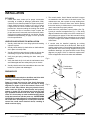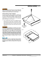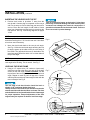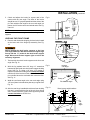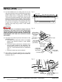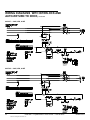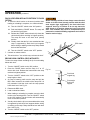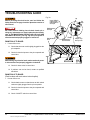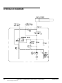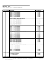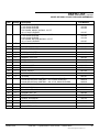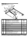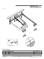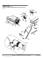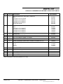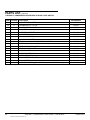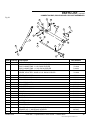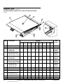
1
HydraulicPlus™
Model “HP”
This User’s Manual applies to
dock levelers manufactured
beginning October 2012 with the
serial number 61059674 and
higher.
Do not install, operate or service this product unless you
have read and understand the Safety Practices, Warnings,
Installation and Operating Instructions contained in this
User’s Manual. Failure to do so could result in death or
serious injury.
User’s Manual
Installation, Operations,
Maintenance and Parts
Part No. 6004750K
Table of contents
Introduction..................................................................2
Safety Signal Words....................................................2
Safety Practices..........................................................3
Owner's Responsibilities.............................................4
Ramp and Lip Grades.................................................5
Installation...................................................................6
Wiring Diagrams – Standard Control Box.................15
Wiring Diagrams – With Optional Interlock................17
Wiring Diagrams With Optional Interlock And
Auto Return To Dock.................................................21
Operation– With Standard Control Box.....................25
Operation – With Optional Auto Return To Dock
Control Box................................................................28
Planned Maintenance................................................31
Maintenance And Lubrication....................................32
Troubleshooting Guide..............................................34
Hydraulic Diagram.....................................................38
Parts Replacement....................................................39
Parts List...................................................................40
Warranty....................................................................71
Distributor Information...............................................72
Introduction
Welcome and thank you for choosing this dock leveler from Kelley®. This dock leveler may be equipped with
the optional ENERGY GUARD® dock leveler sealing system.
This User’s Manual contains information that you need to safely install, operate and maintain the dock leveler. It
also contains a complete parts list and information about ordering replacement parts. Please keep and read this
User’s Manual before using your new dock leveler.
safety signal words
You may find safety signal words such as DANGER, WARNING, or CAUTION throughout this Owner’s Manual.
Their use is explained below:
This is the safety alert symbol. It is used
to alert you to potential personal injury
hazards. Obey all safety messages that
follow this symbol to avoid possible death or injury.
Indicates an imminently hazardous situation which, if
not avoided, will result in death or serious injury.
Indicates a potentially hazardous situation which,
if not avoided may result in minor or moderate
injury.
Indicates a potentially hazardous situation which,
if not avoided, could result in death or serious
injury.
Notice is used to address practices not related to
personal injury.
2
6004750K — HydraulicPlus™ Dock Leveler — SafeTFrame™
©2012 4Front Engineered Solutions, Inc.
October 2012
Safety practices
Read these safety practices before installing, operating
or servicing the dock leveler. Failure to follow the safety
practices could result in death or serious injury.
Do not use a fork truck or other material handling equipment
to lower the ramp.
Before chocking wheels or engaging vehicle restraint, dump
air from air ride suspensions and set parking brakes.
If you do not understand the instructions, ask your supervisor
to explain them to you or call local Kelley distributor.
Ensure lip avoids contact with vehicle sides and cargo. If lip
does not lower to vehicle bed, reposition vehicle.
OPERATION
INSTALLATION, MAINTENANCE AND SERVICE
Use restricted to trained operators.
Follow procedures on placard posted near dock leveler.
Do not use this unit to service vehicles outside its intended
working range which is 12 inches above and 12 inches below
dock. (18" above and 12" below dock on 10' models)
Do not operate the dock leveler with equipment, material or
people on the ramp or lip.
Do not operate the dock leveler when anyone is in front of it
unless they are securing the maintenance strut.
Stay clear of the dock leveler when it is moving.
Keep hands clear of hinges at all times. Do not use hands to
position dock leveler ramp or lip in vehicle or to store dock
leveler.
Do not use the dock leveler if it looks broken or does not
seem to work right. Tell your supervisor it needs repair right
away.
Do not stand in the driveway between the dock leveler and
a backing vehicle.
Place barricades on the dock floor around the dock leveler
pit and in the driveway in front of the pit while installing,
maintaining or repairing the dock leveler.
Do not operate the dock leveler when anyone is in front of it
unless they are securing the maintenance strut.
PUT AND PIN MAINTENANCE STRUT AND LIP LOCK IN
PLACE before climbing into the dock leveler pit or doing any
maintenance or repair under the dock leveler.
Disconnect the power and properly tag or lock off before
climbing into the dock leveler pit or doing any maintenance
or repair under the dock leveler.
All electrical troubleshooting or repair must be done by a
qualified technician and must meet applicable codes.
Disconnect the power and properly tag or lock off before
doing any electrical work.
If it is necessary to make troubleshooting checks inside the
control box with the power on, USE EXTREME CAUTION!
Do not place fingers or uninsulated tools inside the control
box. Touching wires or other parts inside the control box
could result in electrical shock, death or serious injury.
Chock vehicle wheels or lock vehicle in place with a
vehicle restraining device and set brakes before loading or
unloading.
Stay clear of leveler unless lip supported by the vehicle bed
or the ramp is supported by both front dock level supports;
unsupported leveler can lower unexpectedly.
Store dock leveler at dock level after below dock end
loading.
Move all equipment, material or people off dock leveler and
store dock leveler at dock level before allowing the vehicle
to pull out.
October 2012
6004750K — HydraulicPlus™ Dock Leveler — SafeTFrame™
©2012 4Front Engineered Solutions, Inc.
3
Owner’s responsibilities
The owner’s responsibilities include the following:
The owner should recognize the inherent danger of the
interface between dock and transport vehicle. The owner
should, therefore, train and instruct operators in the safe use
of dock leveling devices.
When a transport vehicle is positioned as closely as
practicable to a dock leveling device, there shall be at least
4" of overlap between the front edge of the lip and the edge
of the floor or sill of the transport vehicle.
Nameplates, cautions, instructions and posted warnings shall
not be obscured from the view of operating or maintenance
personnel for whom such warnings are intended.
Manufacturer’s recommended periodic maintenance and
inspection procedures in effect at date of shipment shall be
followed, and written records of the performance of these
procedures should be kept.
Dock leveling devices that are structurally damaged or
have experienced a sudden loss of support while under
load, such as might occur when a transport vehicle is pulled
out from under the dock leveling device, shall be removed
from service, inspected by the manufacturer’s authorized
representative, and repaired as needed before being placed
back in service.
The owner shall see that all nameplates, caution and
instruction markings or labels are in place and legible and
that the appropriate operating and maintenance manuals
are provided to users.
Modifications or alterations of dock leveling devices
shall be made only with written permission of the original
manufacturer.
When industrial vehicles are driven on and off transport
vehicles during the loading and unloading operation, the
brakes on the transport vehicle shall be applied and wheel
chocks or positive restraints that provide the equivalent
protection of wheel chocks engaged.
The dock leveler should never be used outside its vertical
working range or vertical lifting range or outside the
manufacturer’s labeled rated capacity. It must also be
compatible with the loading equipment and other conditions
relating to the dock.
4
6004750K — HydraulicPlus™ Dock Leveler — SafeTFrame™
©2012 4Front Engineered Solutions, Inc.
October 2012
Ramp and lip grades
Fig. 1
Ramp grade
Lip grade
RAMP
LIP
RAMP
LIP
RAMP
LIP
Vehicle bed
position
from dock,
(in.)
18.0
16.0
14.0
----
----
----
----
16.7
15.0
13.2
8.8
7.1
5.4
12.0
10.0
8.0
19.4
16.5
13.7
11.6
8.7
5.8
14.5
12.3
10.2
6.6
4.5
2.4
11.5
9.8
8.2
3.7
2.0
0.3
6.0
4.0
2.0
10.8
8.0
5.2
3.0
0.2
-2.6
8.1
6.0
3.9
0.2
-1.8
-3.9
6.5
4.8
3.1
-1.4
-3.1
-4.7
0.0
2.4
-5.4
1.8
-6.0
1.5
-2.0
-4.0
-6.0
-0.3
-3.1
-5.9
-8.2
-11.0
-13.8
-0.3
-2.3
-4.4
-8.1
-10.2
-12.3
-8.0
-10.0
-12.0
-8.7
-11.5
-14.4
-16.6
-19.4
-22.2
-6.5
-8.6
-10.7
-14.4
-16.5
-18.6
RAMP and LIP grades, % for each Dock Leveler length
4˚ lip bend, 16" lip.
October 2012
8' Leveler
10' Leveler
RAMP and LIP grades, % for each Dock Leveler length
6' Leveler
8' Leveler
10' Leveler
RAMP
LIP
RAMP
LIP
RAMP
LIP
18.0
16.0
14.0
----
----
----
----
17.3
15.6
13.9
4.8
3.0
1.3
12.0
10.0
8.0
20.5
17.6
14.7
8.0
5.0
2.2
15.3
13.1
11.0
2.7
0.6
-1.6
12.2
10.5
8.8
-0.4
-2.1
-3.8
6.0
4.0
2.0
11.9
9.1
6.3
-0.7
-3.5
-6.3
8.9
6.8
4.7
-3.7
-5.8
-7.9
7.1
5.4
3.8
-5.5
-7.1
-8.8
-6.4
0.0
3.5
-9.1
2.6
-10.0
2.1
-10.5
-0.2
-1.9
-3.5
-8.1
-9.7
-11.4
-2.0
-4.0
-6.0
0.7
-2.1
-4.9
-11.9
-14.6
-17.4
0.5
-1.6
-3.6
-12.0
-14.1
-16.2
0.4
-1.2
-2.9
-12.1
-13.8
-15.5
-5.2
-6.9
-7.5
-13.1
-14.7
-15.3
-8.0
-10.0
-12.0
-7.7
-10.5
-13.3
-20.2
-23.0
-25.9
-5.7
-7.8
-9.9
-18.3
-20.4
-22.5
-4.6
-6.3
-7.9
-17.1
-18.8
-20.5
Above dock
6' Leveler
Below dock
Below dock
Above dock
Vehicle bed
position
from dock,
(in.)
7˚ lip bend, 16" lip (Optional special order)
6004750K — HydraulicPlus™ Dock Leveler — SafeTFrame™
©2012 4Front Engineered Solutions, Inc.
5
Installation
PIT CHECK
1. Check entire dock leveler pit for proper construction
according to certified pit drawings (publication 5568).
Check to be sure that the pit walls are square and plumb.
Check electrical service running to the pit to assure
it agrees with the correct location and voltage for the
junction box. Area surrounding the leveling feet should
be smooth and free of excessive lumps. Inspect the
pit and remove all loose trash and construction debris.
Verify the pit matches pit details for your leveler. See the
installation troubleshooting on page 14 if the pit varies
from the specification.
leveler check prior to installation
1. Visually check that the 4 rear hinge pins and retaining
clips are in place.
1. The control station, User’s Manual and dock bumpers
are attached to the sub frame of the dock leveler. The
maintenance strut has a plastic tie wrap holding them
to the subframe. Remove these items before placing
the leveler into the pit. Make sure the customer gets the
user’s manual and is properly trained.
2. Mount and wire push-button control station (See Fig.
2) and pit mounted receptacle.See Fig. 3. See wiring
diagram located on the inside cover of the control box or
wiring diagrams on pages 15-24 of this manual for wiring
information. Follow the wiring instructions to set control
for proper voltage. Wires shown in dashed lines are field
connections.
3. Visually check that cotter pins are in place on pins on the
connecting rod, push bar, and the lip lifter assembly.
3. If conduit must be installed (replacing an existing
mechanical dock leveler) do so at this time. Refer to the
conduit requirements on the pit detail publications 5568
and powered dock leveler wiring diagrams and typical
installation drawings, and powered dock leveler wiring
diagrams on pages 15-24 for electrical requirements.
Follow all applicable electrical codes and standards.
4. Verify that gas spring retaining pins have cotter pins
installed.
Fig. 2
2. Visually check that the lip shaft collars or shaft retainers
are in place on both lip rods.
5. Verify that both the lip lock and the maintenance strut
are undamaged and have safety hitch pins on chains.
6. Visually check that the foot assemblies at the rear of the
leveler are in place and undamaged.
48"
prepare site
Push-button
control station
Place barricades around pit on dock floor and drive while
installing, maintaining or repairing dock leveler.
Power to control box must be from fused disconnect
supplied by others. For correct fuse size refer to wiring
diagrams on pages 15-24 of this manual. Fuses to be
class CC time delay. Before doing any electrical work,
make certain the power is disconnected and properly
tagged or locked off. All electrical work must be done
by a qualified technician and must meet all applicable
codes. If it is necessary to make troubleshooting checks
inside the control box with the power on, USE EXTREME
CAUTION. Do not place fingers or uninsulated tools inside
the control box. Touching wires or other parts inside the
control box could cause electrical shock, resulting in
death or serious injury.
6
Fig. 3
Pit
center
line 10"
12"-13"
Box located as
shown
6004750K — HydraulicPlus™ Dock Leveler — SafeTFrame™
©2012 4Front Engineered Solutions, Inc.
October 2012
Installation, continued
Fig. 4
Before installing the dock leveler, read and follow the
Safety Practices on page 3. Failure to follow the Safety
Practices could result in death or serious injury.
installation of dock leveler
6' and 8' long levelers using a standard 19" subframe can
be field converted to allow installation in a 24" pit by adding
a 4" riser kit, Kelley Part No. 6004654. Install the new riser
leveling feet. The riser blocks should be welded to the front
frame supports prior to placing in the pit. See publication
#6003728 and page 45 in this manual.
1. Prior to lifting leveler make sure the shipping tie down
bolts seen in Fig. 14 are in place. Install two 3/4”-10UNC
load centering eye bolts into the front and rear of the top
plate and hoist leveler into pit. The dock leveler should
not be lifted in any other manner when place into the pit.
See Fig. 4.
Inadequate lifting equipment or practices can cause a
load to fall unexpectedly. Make sure the lifting chain or
other lifting devices are in good condition and have a
rated capacity of at least 3500 lbs for the lifting angle
used. Never allow anyone to stand on or near the dock
leveler when it is lifted or placed into the pit. Stand clear
of the dock leveler when it is placed into the pit. Failure
to follow this warning can allow the dock leveler to fall,
tip, or swing into people, resulting in death or serious
injury.
3/4" - 10 UNC
load centering
eyebolt
Fig. 5
Route power cord clear of edges and resting surfaces
so that it is not damaged during lifting and placement.
Plug end may be routed up through the rear hinge until
needed.
October 2012
6004750K — HydraulicPlus™ Dock Leveler — SafeTFrame™
©2012 4Front Engineered Solutions, Inc.
7
Installation, continued
inserting the leveler into the pit
2. Position dock leveler in pit about 7" away from the
rear pit wall. Connect plug to receptacle on the rear pit
wall. Cut tie wrap on cord to allow bag pan removal for
service. Place the free length of cord inside of frame
area, free of interference as the leveler is moved into the
final position. See Fig. 5 and wiring diagrams on pages
15-24.
NOTE:
Check the pit floor for uneven or excess concrete in the area
around the leveling feet 1"-6" from the rear wall. Use chisel
to level out area if necessary.
Turn off all electrical power to the leveler if it has been
previously connected. Welding with dock levelers power
connected can damage the electrical components. A
ground must be attached to the leveler frame. Failure to
do so can result in product damage.
Fig. 6
3. Move the dock leveler back to the rear pit curb angle.
See Fig. 6. With the rear leveler angle touching the rear
pit angle, square up the sides of the pit to the sides of
the leveler. The gap should be even on both sides. The
rear frame angle should be within 1/4" on either sides of
the pit curb angle.
NOTE:
The rear frame angle should be about 1/2" lower than the pit
curb angle before leveling. This is normal. See Fig. 7.
leveling the rear frame
4. Using a 1/2" square drive (1/2" ratchet or impact tool)
work from one side to the other, turn each of the leveling
screws on the rear angle, counter-clockwise until the
top surface of the rear angle is level with the rear pit curb
angle. Repeat on each leg until all legs are in contact
with the pit floor and the top frame angle is flush with the
rear curb angle. See Fig 8.
Fig. 7
1/2"
The rear edge of the dock leveler should be level or
slightly (1/16" maximum) below dock level.
The top surface of the dock leveler should be level and a
smooth transition with the dock floor curb steel. The front
end should be level and parallel with the rear frame angle
for proper operation. Unequal adjustment of the front
supports may be required to obtain a level front edge.
1/2"
8
6004750K — HydraulicPlus™ Dock Leveler — SafeTFrame™
©2012 4Front Engineered Solutions, Inc.
October 2012
Installation, continued
5. Check and adjust the leveler for square and in firm
contact with the rear angle. The sides of the leveler
should have a 1/2" gap and parallel with the sides of the
pit. Tack weld the rear angle to the rear curb angle in 4
places min 3/8" at the center and at both ends. See Fig.
9 and 10.
Fig. 8
Raises
rear
angle
NOTE:
Do not weld out the rear angle until after setting the front
supports.
leveling the FRONT frame
6. Remove and discard the shipping tie down bolts located
at the lower end of the hinged lip assembly. See Fig.
14.
Before welding the dock leveler supports to the front
curb angle make sure that the dock leveler support legs
line up with the “V” pocket in the dock leveler support
angle. Move dock levelers support right or left for the
necessary alignment.
Leg
adjustment
7. Tack weld the front dock leveler supports to the front curb
angle. See Fig. 12.
8. With the lip pendant insert 24" long 1/2" extensions
between lip and lip rod onto dock leveler support leveling
screw. See Fig. 12. Using a 1/2" drive (1/2" ratchet or
impact tool) turn each leveling screw counter-clockwise
until the top of the levelers is flush with the finished floor/
pit curb steel where the overhead door meets the floor.
See Fig. 11.
Fig. 9
Rear pit
curb angle
1/2"
Ramp
9. Weld the rear frame angle to the rear curb angle using
1/4" bevel joints in the transition plate as your guide. See
Fig. 10.
10. After the rear hinge is welded check that all rear leveling
legs are in contact with the floor of the pit. Once all legs
are in contact with floor, tighten each leg leveling screw
counter-clockwise to 25-40 ft. lbs.
Rear
frame
angle
1/2"
Pit side curb angle
Fig. 10
Bevel groove weld locations
5"
5"
2-1/2"
5"
2-1/2"
5"
2-1/2"
5"
2-1/2"
Frame
uprights
October 2012
5"
Pit
rear
curb
angle
Rear hinge
assembly
6004750K — HydraulicPlus™ Dock Leveler — SafeTFrame™
©2012 4Front Engineered Solutions, Inc.
9
Installation, continued
11. If a field installed riser kit is being used, do not use
hydraulics to position leveler on maintenance strut before
cylinder support riser is in place. Use a suitable lifting
device to place leveler on maintenance strut per step
12 below, then position and weld in the cylinder support
bracket. If electrical power is available, reconnect power
and use the electrical controls to raise the ramp and lip to
their full above dock position. See operating instructions
on front cover of control box. If electrical power in not
available, raise ramp using a chain or other suitable
lifting device.
Fig. 11
Hydraulic pressure or mechanical support must be
maintained on the ramp to hold it in the raised position
until the maintenance strut is in place. DO NOT WORK
UNDER THE DOCK LEVELER RAMP OR LIP UNLESS THE
MAINTENANCE STRUT AND LIP LOCK ARE IN PLACE
AND PINNED.
Fig. 12
12. Two people are needed to place the dock leveler on the
maintenance strut.
a. One person must hold dock leveler in its highest
position with electrical controls or other suitable
lifting device.
b. The second person positions the mintenance strut
into the bracket located on the underside of the
ramp assembly and pins it in place with hairpin clip.
See Fig. 15 and instruction label on maintenance
strut.
c. Electrical controls may now be released.
3/16" weld
(both sides)
Door jamb
Flush with floor at this point
1/2" sq. drive
adjustment bolt
CCW rotation
to raise
3/16" weld
3/16" weld
3" long (min.)
3/16" weld
3" long (min.)
(both sides)
Curb steel
3/16" weld
(both sides)
3/16" weld
3" long (min.)
(both sides)
Curb steel
13. 6x16" shims of the proper thickness are to be placed
under the ramp cylinder mounting pad and welded out
as shown in Fig. 13.
3/16" weld
3" long (min.)
Fig. 13
3/4"
anchor
bolt
(supplied
by others)
10 Cylinder
mounting pad Stagger and weld
6" x 12" shims
6004750K — HydraulicPlus™ Dock Leveler — SafeTFrame™
©2012 4Front Engineered Solutions, Inc.
October 2012
Installation, continued
Fig. 14
Manual support of the lip must be maintained until the lip
lock is in place. The lip is free to move downward when
it is released unless the lip lock is pinned in place. DO
NOT WORK UNDER THE DOCK LEVELER RAMP OR LIP
UNLESS THE MAINTENANCE STRUT AND LIP LOCK ARE
IN PLACE AND PINNED.
14. Manually lift the hinged lip into the raised position and
lock into place with the lip lock provided on the dock
leveler ramp. Pin lip lock in place with hairpin clip. See
Fig. 15 and instruction label located on the underside of
the dock leveler ramp.
Welding with the dock levelers power connected can
damage electrical components. If the dock leveler has
been previously connected, turn off power to control
box and unplug all electrical cords from receptacles in
rear pit wall before welding. Failure to do so can result
in product damage.
15. Finish welding both of the adjusted dock leveler supports
in all locations shown in Fig. 12.
Shipping tie
down bolt
Fig. 15
Insert hairpin
clip through
maintenance
strut pin
Lip
Lip
lock
Maintenance
strut pin
Maintenance
strut
Ramp
Maintenance
strut bracket
Insert
hairpin clip
into lip lock
16. Check shims under ramp cylinder pad. Adjust thickness
if necessary.
Improper installation of anchoring devices or installation
into aged or unsound concrete could result in death or
serious injury.
17. Drill and install 3/4" diameter anchor bolts (min. 3" deep)
in ramp cylinder mounting pad. Weld shims to pad as
noted in Fig 13.
18. Remove and discard shipping cotter pins from toe
guards on both sides of dock leveler. See Fig. 16.
Fig. 16
19. Remove lifting chain or other lifting devices. Remove
lifting hooks from the sides of the ramp.
20. Read the Safety Practices on page 3, and the Operation
Instructions on pages 25 through 30 before operating
the dock leveler.
Remove
shipping cotter
pins
October 2012
6004750K — HydraulicPlus™ Dock Leveler — SafeTFrame™
©2012 4Front Engineered Solutions, Inc.
11
installation, continued
Fig. 17
Improper installation of anchoring devices or installation
into aged or unsound concrete could result in death or
serious injury.
Molded "L" bumpers
1" Dia.
4"
3"
The dock face must be flush with curb angle to assure
proper bumper mounting.
21. Mount dock bumpers to face of dock. Downhill welds are
unacceptable. See Fig. 17 or 18.
J bolts (3) per bumper
furnished by Kelley
Company, Inc. locate
and weld to curb
angle at time of
bumper installation.
22. Plug or wire in electrical cords and connect power to
dock leveler.
Manually support the lip when storing the lip lock. Stand
clear of the lip when removing support. The lip is free to
move downward when support is removed. Anyone in the
path of the lip when it moves downward can be struck.
Keep your hands, fingers and head away from the lip
when it is released. They could be struck by the lip or
caught between the lip and other parts of the dock leveler
resulting in death or serious injury.
DO NOT REMOVE MAINTENANCE STRUT WITHOUT
HYDRAULIC PRESSURE OR A MECHANICAL LIFTING
DEVICE SUPPORTING RAMP. Raise ramp with
hydraulic pressure or mechanical device before storing
maintenance strut. Stand clear of ramp and lip when
hydraulic pressure or mechanical lift is applied or
removed. Ramp and lip are free to move downward
when support is removed. Removing support without
hydraulic pressure could allow ramp to drop RAPIDLY. If
the dock leveler was raised using a mechanical device,
it should be lowered using the same device.
Fig. 18
Laminated bumpers
3/8" side of pit
to side of bumper
mounting plate
1/4"
Full length of bumper
mounting plate.
downhill welds are
unacceptable.
Vertical
bumper
mounting
angle
Laminations must be
installed vertically
To
curb
angle
1/4"
3/4" dia.
anchor bolt.
field installed.
supplied by
others.
23. Lift up on the hinged lip and store the lip lock under the
ramp.
24. Two people are needed to store the maintenance strut.
a.One person must push and hold the raise button
until dock leveler reaches its highest position and
hold dock leveler in its highest position.
12 6004750K — HydraulicPlus™ Dock Leveler — SafeTFrame™
©2012 4Front Engineered Solutions, Inc.
October 2012
installation, continued
b.The second person unpins the maintenance strut
from the bracket on the ramp and stores it on the
subframe. See Fig. 15 and the instruction label on
maintenance strut
Fig. 19
OP
ER
AT
Warning and operating
instruction placard
IONS
c. The raise button may now be released. The ramp
will lower and the lip will extend when the button is
released.
The hinged lip will extend as the ramp moves down.
25. Place the dock leveler in both dock leveler storage
position and full below dock end load position. If lip is
being supported by the curb steel in either position, a
deflector plate must be created to allow leveler to store
and reach its full below dock position without getting
hung up on the pit floor.
Improper installation that allows the pendant dock leveler
lip to support the weight of the dock leveler could result
in death or serious injury. It is sometimes necessary to
install lip deflector plates to avoid any chance of the
pendant lip supporting the weight of the dock leveler
either near dock level or during a below dock end load.
Fig. 20
Rear angle
Cap plug
26. Permanently mount the laminated dock leveler
WARNING and OPERATING instruction placard on the
wall near the dock leveler control. See Fig. 19. Make
sure the customer gets the user’s manual and is properly
trained. Make sure customer gets user's manual and is
properly trained.
27. Operate the dock leveler four times through the complete
cycle to check operation. (See Operation section, page
25.)
NOTE:
If you have any problems or questions using or operating
the dock leveler, contact your supervisor or local Kelley®
distributor for assistance.
28. Optional (where applicable), install rear angle cap plugs
(part number 6004488) into adjustment socket holes.
Press cap flush with top surface to rear angle. See Fig.
20.
October 2012
6004750K — HydraulicPlus™ Dock Leveler — SafeTFrame™
©2012 4Front Engineered Solutions, Inc.
13
installation, continued
installation troubleshooting
The following procedures apply after the leveler is level in
the pit.
PROBLEM
POSSIBLE CAUSE
1)Leveler will not fit properly in pit.
a) Pit is out of square with the sides.
a)Align the sides parallel and equally
spaced with the rear frame angle
touching the rear curb angle in one
place. Fill the gap between the rear
curb angle and rear frame angle using
shims in weld pattern noted in Fig. 10.
See Fig 21.
b) One side and rear angle is out of
square.
b) Align the leveler with the two square
edges. The gap on the sides should
be even in the most narrow section
(1/2" Max. per side). See Fig. 22.
c) Pit floor irregular in rear.
c) If large deformations exist in the
concrete work, attempt to flatten
out the rough surface using a chisel
or grinder to take out the large
obstructions. The rear leveling legs
can be installed on out of plane
surfaces up to 1/8" at each leg. See
Fig. 23.
d)Pit is too deep.
d) Weld 4" x 4" shims to the bottom of
the adjustable legs.
Fig. 22
Fig. 21
SOLUTION
Fig. 23
Shim and weld flush
Equal
gap
1/2" max.
1/8" max
allowable step
no greater than
1" x 3" in size
6"
contact
zone
14 6004750K — HydraulicPlus™ Dock Leveler — SafeTFrame™
©2012 4Front Engineered Solutions, Inc.
October 2012
Wiring diagrams — control box — standard
Before doing any electrical work, make certain the power
is disconnected and properly tagged or locked off. All
electrical work must be done by a qualified technician
and meet all applicable codes. If it is necessary to make
troubleshooting checks inside the control box with
the power on, USE EXTREME CAUTION. Do not place
your fingers or uninsulated tools inside the control box.
Touching wires or other parts inside the control box
could result in electrical shock, death or serious injury.
NOTE:
For 24V incoming power consult factory.
6006461 — 120V, 1 PH, 50/60 Hz
6006462 — 208-240V, 1 PH, 60 Hz
October 2012
6004750K — HydraulicPlus™ Dock Leveler — SafeTFrame™
©2012 4Front Engineered Solutions, Inc.
15
Wiring diagrams — standard
6006450 — 208-230V, 3PH, 50/60 Hz
6006451 — 460-480V, 3PH, 60 Hz
16 6004750K — HydraulicPlus™ Dock Leveler — SafeTFrame™
©2012 4Front Engineered Solutions, Inc.
October 2012
Wiring diagrams — standard, continued
6006452 — 575V, 3PH, 60 Hz
Wiring diagrams with interlock
6011372 — 120V, 1ph, 60 hz
October 2012
6004750K — HydraulicPlus™ Dock Leveler — SafeTFrame™
©2012 4Front Engineered Solutions, Inc.
17
Wiring diagrams with interlock, continued
6011524 — 208/230V, 1PH, 60 Hz
18 6004750K — HydraulicPlus™ Dock Leveler — SafeTFrame™
©2012 4Front Engineered Solutions, Inc.
October 2012
Wiring diagrams with interlock, continued
6011325 — 208V, 3PH, 60 hz
6011761 — 240V, 3PH, 60 HZ
October 2012
6004750K — HydraulicPlus™ Dock Leveler — SafeTFrame™
©2012 4Front Engineered Solutions, Inc.
19
Wiring diagrams with interlock, continued
6011326 — 460-480V, 3ph, 60 hz
6011651 — 575V, 3PH, 60 Hz
20 6004750K — HydraulicPlus™ Dock Leveler — SafeTFrame™
©2012 4Front Engineered Solutions, Inc.
October 2012
Wiring diagrams with interlock and
auto-return to dock
6011323 — 120V, 1PH, 60 Hz
6011324 — 208/240V, 1PH, 60 hz
October 2012
6004750K — HydraulicPlus™ Dock Leveler — SafeTFrame™
©2012 4Front Engineered Solutions, Inc.
21
Wiring diagrams with interlock and
auto-return to dock, continued
6011327 — 208V, 3PH, 60 hz
6011762 — 240V, 3PH, 60 hz
22 6004750K — HydraulicPlus™ Dock Leveler — SafeTFrame™
©2012 4Front Engineered Solutions, Inc.
October 2012
Wiring diagrams with interlock and
auto-return to dock, continued
6011328 — 460-480V, 3ph, 60 hz
October 2012
6004750K — HydraulicPlus™ Dock Leveler — SafeTFrame™
©2012 4Front Engineered Solutions, Inc.
23
Wiring diagrams with interlock and
auto-return to dock, continued
6011652 — 575V, 3PH, 60 Hz
NOTE:
For 24V incoming power consult factory.
24 6004750K — HydraulicPlus™ Dock Leveler — SafeTFrame™
©2012 4Front Engineered Solutions, Inc.
October 2012
Operation
DOCK LEVELERS WITH STANDARD CONTROL BOX
Before operating the dock leveler, read and follow Safety
Practices on page 3.
Use of dock leveler restricted to trained operators.
Follow procedures on placard posted near leveler
DO NOT USE THE DOCK LEVELER IF IT LOOKS
BROKEN, OR DOES NOT SEEM TO WORK RIGHT. Tell
your supervisor it needs repair right away.
Before pressing button, ensure lip avoids contact with
vehicle sides and cargo. If lip does not lower to vehicle
bed, reposition vehicle.
Stay clear of leveler unless lip is supported by vehicle
bed or the leveler is stored at dock level. Visually check
that the lip is supported by the vehicle bed or the ramp
is supported by both dock level supports before driving
or walking on the ramp. Unsupported dock levelers can
lower unexpectedly.
Before chocking wheels or engaging vehicle restraint,
dump air from air ride suspensions and set parking
brakes.
Always be certain that the vehicle wheels are chocked,
or that the vehicle is locked in place by a vehicle
restraining device and the brakes are set before loading
or unloading. Vehicles pulling away from the dock
unexpectedly can cause uncontrolled drop of the dock
leveler which can result in death or serious injury.
INTRODUCTION
The KELLEY HydraulicPlus™ dock leveler is designed to
span and compensate for space and height differences
between a loading dock and freight carrier to allow safe,
efficient freight transfers.
The KELLEY HydraulicPlus™ dock leveler uses a push-button
control to position the dock leveler. Pushing and holding the
push-button operates a hydraulic cylinder to raise the ramp.
Releasing the push-button allows the ramp to lower.
A mechanical linkage extends the dock leveler lip as the ramp
lowers from its full raised position, and the leveler with its lip
extended settles onto the vehicle bed forming a bridge.
After loading, pushing and holding the push-button raises
the ramp, and the extended lip lowers to its stored position.
Releasing the push-button (before the dock leveler reaches
its highest position) allows the dock leveler to lower to its
level, stored position.
With the dock leveler in its stored position, dock level support
legs support the dock leveler ramp at a position level with
the dock floor.
The dock level support legs will retract when the dock leveler
lip is extended, allowing the ramp and lip to lower onto and
follow the vehicle bed up and down as loads are moved
across the dock leveler and vehicle.
The maximum uncontrolled drop of a Kelley HP dock
leveler from any position is 3 inches.
Always return the dock leveler to its dock level (stored)
position before allowing vehicle to leave dock. If vehicle
pulls away from dock before dock leveler is stored, the
lip will fall to its pendant position and the ramp will drop.
In addition, failure to properly store the dock leveler
may leave the leveler in a position below the level of the
floor. This condition may result in unexpected drop of
personnel or material handling equipment and result in
death or serious injury.
Failure to follow these instructions could result in death
or serious injury to operators and/or bystanders.
October 2012
6004750K — HydraulicPlus™ Dock Leveler — SafeTFrame™
©2012 4Front Engineered Solutions, Inc.
25
OperatION, continued
DOCK LEVELERS WITH STANDARD CONTROL BOX
1. Do not operate the dock leveler until a vehicle is in
position against the dock bumpers.
Fig. 25
2. Tell vehicle driver “Your vehicle must stay at the dock.”
3. Chock or hitch vehicle.
4. If necessary, remove end loads with the ramp in the dock
level (stored) position. See Fig. 25.
NOTE:
If the vehicle to be serviced is below dock level, see operating
instructions for Below Dock Control (BDC) on page 27.
Dock level
supports
Fig. 26
Control box mounted to wall
5. To extend the dock leveler lip into the vehicle:
5.1 Push and hold the control button. The ramp will rise
until it stops at its highest position. See Fig. 26.
5.2 Release the control button when the ramp reaches
its highest position.
5.3 Ramp and lip will lower and lip will extend until the
lip rests on the vehicle bed. See Fig. 27.
Lip extend
Ramp
Vehicle bed
Do not operate the dock leveler when anyone is on or in
front of it.
Stay clear of the dock leveler when it is moving.
Do not drive on dock leveler or lip until it is fully extended
and supported by the vehicle bed.
Fig. 27
Never use a fork truck or other material handling
equipment to lower the ramp and lip sections.
5.4 Proceed with loading or unloading.
26 6004750K — HydraulicPlus™ Dock Leveler — SafeTFrame™
©2012 4Front Engineered Solutions, Inc.
October 2012
OperatION, continued
DOCK LEVELERS WITH STANDARD CONTROL BOX
6. To return the dock leveler to the stored position when
loading or unloading is complete, or to load end loads:
6.1 Push and hold the control button. The ramp will rise
and the lip will lower.
6.2 Release the control button when the lip clears the
vehicle bed (before reaching its highest position).
The ramp will lower to the dock level (stored)
position.
Before allowing vehicle to leave always return the dock
leveler to its dock level (stored) position with the dock
level support legs supported by the front dock level
supports and the lip hanging pendant. See Fig. 29. Failure
to do so may leave the dock leveler in a position below
the level of the dock floor. This condition may result
in unexpected drop of personnel or material handling
equipment and result in death or serious injury.
6.3 Visually check that the lip is not extended or hung
upon trailer. Ramp should be level with dock floor.
7. Unchock or release vehicle.
8. Tell vehicle driver “Your vehicle may now leave the
dock.”
Fig. 28
BDC chain
BELOW DOCK CONTROL (BDC):
To lower the ramp without extending the lip for end loading
below dock level:
1. Press the control button and hold it until the ramp is 6"
to 12" above dock level. Release the button before the
ramp reaches its highest position.
2. As ramp is lowering, walk onto the ramp and pull the
BDC chain located in the middle of the ramp until it is
fully extended. Hold the chain until the ramp passes
below dock level. See Fig. 28.
Fig. 29
3. Release the BDC chain.
Dock level
support leg
4. Load or unload end loads.
5. When loading or unloading is complete, return the dock
leveler to the stored position.
Front angle
dock level
support
5.1 Push and hold the control button until the ramp is at
least 4" above dock level.
5.2 Release the control button before the ramp reaches
its highest position. The ramp will lower to its stored
position.
5.3 Visually check that the lip is not extended and the
ramp is supported by both dock level supports
before driving or walking on the ramp. Ramp should
be level with dock floor. See Fig. 29.
6. Unchock or release vehicle.
7. Tell vehicle driver “Your vehicle may now leave the
dock”.
October 2012
6004750K — HydraulicPlus™ Dock Leveler — SafeTFrame™
©2012 4Front Engineered Solutions, Inc.
27
Operation
DOCK LEVELERS WITH auto-return to dock
option
Before operating the dock leveler, read and follow Safety
Practices on page 3.
Use of dock leveler restricted to trained operators.
Follow procedures on placard posted near leveler
DO NOT USE THE DOCK LEVELER IF IT LOOKS
BROKEN, OR DOES NOT SEEM TO WORK RIGHT. Tell
your supervisor it needs repair right away.
Before pressing button, ensure lip avoids contact with
vehicle sides and cargo. If lip does not lower to vehicle
bed, reposition vehicle.
Stay clear of leveler unless lip is supported by vehicle
bed or the leveler is stored at dock level. Visually check
that the lip is supported by the vehicle bed or the ramp
is supported by both dock level supports before driving
or walking on the ramp. Unsupported dock levelers can
lower unexpectedly.
Before chocking wheels or engaging vehicle restraint,
dump air from air ride suspensions and set parking
brakes.
Always be certain that the vehicle wheels are chocked,
or that the vehicle is locked in place by a vehicle
restraining device and the brakes are set before loading
or unloading. Vehicles pulling away from the dock
unexpectedly can cause uncontrolled drop of the dock
leveler which can result in death or serious injury.
INTRODUCTION
The KELLEY HydraulicPlus™ dock leveler is designed to
span and compensate for space and height differences
between a loading dock and freight carrier to allow safe,
efficient freight transfers.
The KELLEY HydraulicPlus™ dock leveler uses a push-button
control to position the dock leveler. Pushing and holding the
push-button operates a hydraulic cylinder to raise the ramp.
Releasing the switch allows the ramp to lower.
A mechanical linkage extends the dock leveler lip as the ramp
lowers from its full raised position, and the leveler with its lip
extended settles onto the vehicle bed forming a bridge.
After loading, moving and holding the push-button raises
the ramp, and the extended lip lowers to its stored position.
Releasing the switch (before the dock leveler reaches its
highest position) allows the dock leveler to lower to its level,
stored position.
With the dock leveler in its stored position, dock level support
legs support the dock leveler ramp at a position level with
the dock floor.
The dock level support legs will retract when the dock leveler
lip is extended, allowing the ramp and lip to lower onto and
follow the vehicle bed up and down as loads are moved
across the dock leveler and vehicle.
The maximum uncontrolled drop of a Kelley HP dock
leveler from any position is 3 inches.
Always return the dock leveler to its dock level (stored)
position before allowing vehicle to leave dock. If vehicle
pulls away from dock before dock leveler is stored, the
lip will fall to its pendant position and the ramp will drop.
In addition, failure to properly store the dock leveler
may leave the leveler in a position below the level of the
floor. This condition may result in unexpected drop of
personnel or material handling equipment and result in
death or serious injury.
Failure to follow these instructions could result in death
or serious injury to operators and/or bystanders.
28 6004750K — HydraulicPlus™ Dock Leveler — SafeTFrame™
©2012 4Front Engineered Solutions, Inc.
October 2012
Operation, continued
DOCK LEVELERS WITH auto-return to dock
option
Fig. 30
1. Do not operate the dock leveler until a vehicle is in
position against the dock bumpers.
2. Tell vehicle driver “Your vehicle must stay at the dock.”
3. Chock or hitch vehicle.
4. If necessary, remove end loads with the ramp in the dock
level (stored) position. See Fig. 30.
NOTE:
If the vehicle to be serviced is below dock level, see operating
instructions for Below Dock Control (BDC) on page 30.
Dock level
supports
Fig. 31
5. To extend the dock leveler lip into the vehicle:
5.1 Turn the “ON/OFF” switch to the “ON” position. See
Fig. 31.
5.2 Push and hold the “RAISE” button. The ramp will
rise until it stops at its highest position. See Fig.
31.
5.3 Release the “RAISE” button. Ramp will lower and
lip will extend until the lip rests on the vehicle bed.
See Fig. 32.
Control box
mounted
on wall
Lip extend
Ramp
Vehicle bed
Do not operate the dock leveler when anyone is on or in
front of it.
Stay clear of the dock leveler when it is moving.
Do not drive on dock leveler or lip until it is fully extended
and supported by the vehicle bed.
Fig. 32
Never use a fork truck or other material handling
equipment to lower the ramp and lip sections.
5.4 Proceed with loading or unloading.
October 2012
6004750K — HydraulicPlus™ Dock Leveler — SafeTFrame™
©2012 4Front Engineered Solutions, Inc.
29
OperatION, continued
DOCK LEVELERS WITH auto-return to dock
option
6. To return the dock leveler to the stored position when
loading or unloading is complete, or to load end loads:
6.1 Turn the “ON/OFF” switch to the “ON” position.
6.2 Push and hold the “RAISE” button. The ramp will
rise and the lip will lower.
6.3 Release the “RAISE” button when the lip clears the
vehicle bed (before reaching its highest position).
The ramp will lower to the dock level (stored)
position.
6.4 Visually check that the lip is not extended and the
ramp is supported by both dock level supports
before driving or walking on the ramp. Ramp should
be level with dock floor.
Before allowing vehicle to leave always return the dock
leveler to its dock level (stored) position with the dock
level support legs supported by the front dock level
supports. See Fig. 34. Failure to do so may leave the
dock leveler in a position below the level of the dock
floor. This condition may result in unexpected drop of
personnel or material handling equipment and result in
death or serious injury.
Fig. 33
BDC chain
6.5 Turn the “ON/OFF” switch to the “OFF” position.
7. Unchock or release vehicle.
8. Tell vehicle driver “Your vehicle may now leave the dock.”
BELOW DOCK CONTROL (BDC) WITH ARTD:
To lower the ramp without extending the lip for end loading
below dock level:
1. Turn the “ON/OFF” switch to the “ON” position.
2. Press the “RAISE” button until the ramp is 6" to 12"
above dock level. Release the button before the ramp
reaches its highest position.
Fig. 34
3. Turn the “ON/OFF” switch to the “OFF” position as the
ramp begins to lower.
4. As ramp is lowering, walk onto the ramp and pull the
BDC chain located in the middle of the ramp until it is
fully extended. Hold the chain until the ramp passes
below dock level. See Fig. 33.
Dock level
support leg
Front angle
dock level
support
5. Release the BDC chain.
6. Load or unload end loads.
7. When loading or unloading is complete, return the dock
leveler to the stored position. Turn the “ON/OFF” switch
to the “ON” position. The dock leveler will automatically
return to the stored position.
8. Visually check that the lip is not extended and the ramp
is supported by both dock level supports before driving
or walking on the ramp. Ramp should be level with dock
floor. See Fig. 34.
9. Turn the “ON/OFF” switch to the “OFF” position.
30 6004750K — HydraulicPlus™ Dock Leveler — SafeTFrame™
©2012 4Front Engineered Solutions, Inc.
October 2012
Planned maintenance
Every 90 days (quarterly) inspect all safety labels and tags
to ensure they are on the dock leveler and are easily legible.
If any are missing or require replacement, please call your
local Kelley distributor.
Fig. 35
700-136
6008485 (x2)
138-837 (x2)
921-074
921-070
OPERATIONS
6004006
(STANDARD)
6004011
(WITH ARTD)
WARNING AND OPERATION PLACARD
(MOUNTED ON WALL NEAR LEVELER)
October 2012
6004750K — HydraulicPlus™ Dock Leveler — SafeTFrame™
©2012 4Front Engineered Solutions, Inc.
31
Maintenance and lubrication
Fig. 36
Before servicing the dock leveler, read and follow the
Safety Practices on page 3 and the Operation section of
this manual.
Lip hinge
pins
Dock level
support leg
cam and hinge
Place barricades on the dock floor around the dock
leveler pit and in the driveway in front of the pit while
installing, maintaining or repairing the dock leveler.
Be certain, before climbing into the dock leveler pit or
doing any maintenance or repair under the dock leveler,
that: 1) THE MAINTENANCE STRUT AND LIP LOCK ARE
SECURELY IN PLACE [see Fig. 38 on page 34] and 2) the
power is disconnected and properly tagged or locked
off.
Ramp
hinge
pins
Cylinder
pivot pin
Hydraulic oil
reservoir
Lip extension
mechanism
Use only lubricants shown. lmproper lubrication or
adjustments may cause operational problems.
Every 90 days inspect dock bumpers. Four inches (4") of
bumper protection is required. Worn, torn, loose or missing
bumpers must be replaced.
MAINTENANCE AND LUBRICATION CHART
Dock Level
Support Leg
Cam & Pivot Pins
Lip & Ramp
Hinge Pins
Lip Extension
Mechanism
Cylinder
Pivot Pins
Dock Leveler
Pit
Rear
Support
Legs
Lubrication
Every 90 Days
SAE 30 On
Pivot Pins &
Grease Cam
Every 90 Days
SAE 30
Every 90 Days
SAE 30
Grease front
push bar
Every 90 Days
SAE 30
Not Required
Not Required
Cleaning
As Required To
Remove Debris
Every 90 Days
As Required To As Required To As Required To
or As Required To
Remove Debris Remove Debris Remove Debris
Remove Debris
As Required To
Remove Debris
Check all labels every 90 days. See pages 38-58 for location and part numbers.
Replace if required.
Every 90 days visually inspect all welds under the leveler for fatigue or failure,
particularly the lip plate hinge and ramp beams and front hinge lugs.
* Acceptable Hydraulic Oils:
Mobil Aero HFA (49011)
Exxon Univis Grade JI3
Texaco Aircraft Oil #1554
U.S. Oil Co., Inc. #ZFI-5606 (Low Temp.)
32 6004750K — HydraulicPlus™ Dock Leveler — SafeTFrame™
©2012 4Front Engineered Solutions, Inc.
October 2012
Maintenance and lubrication, continued
Fig. 37
Legend
Symbol
Description
Lubricate - Oil
Light Oil - SAE 30
Lubricate - Grease
Molybdenum Disulfide
NLGI #2
Cleaning
(Location - Frequency)
Visually Inspect
(Replace Damaged Or Worn)
Hydraulic reservoir
see note 1
Pit - 3 mo
Rear hinge pin
October 2012
6004750K — HydraulicPlus™ Dock Leveler — SafeTFrame™
©2012 4Front Engineered Solutions, Inc.
33
Troubleshooting guide
Fig. 38
Before servicing the dock leveler, read and follow the
Safety Practices on page 3 and the Operation section of
this manual.
Be certain, before climbing into the dock leveler pit or
doing any maintenance or repair under the dock leveler,
that: 1) THE MAINTENANCE STRUT AND LIP LOCK ARE
SECURELY IN PLACE, [see Fig. 38] and 2) the power is
disconnected and properly tagged or locked off.
RAMP FAILS TO RAISE:
Lip
Insert hairpin
clip through
maintenance
strut pin
Lip
lock
Maintenance
strut pin
Maintenance
strut
Ramp
Maintenance
strut bracket
Insert
hairpin clip
into lip lock
1. If motor fails to run:
1.1 Check that the motor cord is tightly plugged into the
pit receptacle.
1.2 Check for electrical power to the pit receptacle and
control box.
Before doing any electrical work, make certain the power
is disconnected and properly tagged or locked off.
1.3 Check for loose wires in control box.
1.4 If problem can not be found, contact a qualified
electrician.
RAMP FAILS TO RAISE:
(Dock levelers with auto-return to dock option)
1. If motor fails to run:
1.1 Check that the motor cord and return to dock switch
cords are tightly plugged into the pit receptacle.
1.2 Check for electrical power to the pit receptacle and
control box.
1.3 Check “ON/OFF” switch on control box.
34 6004750K — HydraulicPlus™ Dock Leveler — SafeTFrame™
©2012 4Front Engineered Solutions, Inc.
October 2012
troubleshooting guide, continued
Fig. 39
Use type 5606 (low temp.)
hydraulic oil.
Before doing any electrical work, make certain the power
is disconnected and properly tagged or locked off.
3"- 4"
1.2 Check for loose wires in control box.
Check oil level with ramp
raised and lip extended
1.3 Check fuses. Replace if required.
1.4 If problem can not be found, contact a qualified
electrician.
2. If motor runs:
2.1 Check hydraulic oil level in reservoir. Add if required.
See Fig. 39 for proper levels and types of oil to be
used.
2.2 Check for loose hydraulic hose fittings or broken
hoses. Repair or replace as required.
2.3 Check for binding in ramp cylinder pivots.
2.4 Check hydraulic bypass pressure and adjust as
required. See Fig. 40. (Turn in to increase - turn
out to decrease) Replace cap and tighten when
finished.
Fig. 40
Set bypass pressure at
2000 PSIG with ramp
raised and lip
extended.
A
Lip fails to extend:
1. Check to make sure that the lip extension mechanism is
not bent or binding. See Fig. 41.
RV1, bypass
pressure adjusting
screw. Turn screw
clockwise to
increase pressure
2. Check to make sure that the lip extension mechanism is
lubricated properly. Lubricate as required.
3. Make sure all pins and pin retainers are in place and in
good condition.
Lip EXTENDS BUT FAILS TO STAY IN EXTENDED
POSITION:
1. Check to see that the lip extension mechanism center
bolt is straight and free to rotate. See Fig. 41.
2. Check to see that the lip extends far enough to allow
the links and connecting rod to align and then reach an
“over center” position. Detail A
Bypass pressure locking nut
Fig. 41
Hanger bracket
Swing link
Notch
Dock leveler ramp
Lip
Roller
Center bolt
Connecting rod
Push Bar
October 2012
6004750K — HydraulicPlus™ Dock Leveler — SafeTFrame™
Pit Floor
©2012 4Front Engineered Solutions, Inc.
35
Troubleshooting guide, continued
LIP fails TO lower TO THE stored POSITION
When the dock leveler is raised from
vehicle:
Fig. 42
1. Check the lip extension mechanism for free movement.
See Fig. 41.
2. Inspect the lip extension mechanism for bent parts.
Be sure all parts are clean, lubricated and have free
movement. See Fig. 41.
1
3. Make sure all pins are in correct position and in good
condition. See Fig. 42.
Ramp will not return to stored position
from full below dock position:
LIP SIZE
2
3
LIP CAPACITY
25K
30K & 35K
40K, 45K & 50K
6 FT-16"
HOLE 3
HOLE 2
HOLE 1
6 FT-18"
HOLE 2
HOLE 1
HOLE 1
6 FT-20"
HOLE 1
HOLE 1
HOLE 1
NOTE:
Ramp will not raise if a lift vehicle or other heavy material is
left on top of the ramp.
6-1/2 FT-16"
HOLE 2
HOLE 1
HOLE 1
6-1/2 FT-18"
HOLE 1
HOLE 1
HOLE 1
6-1/2 FT-20"
HOLE 1
HOLE 1
HOLE 1
1. Check to be sure the control box switch is in the “ON”
position.
7 FT-16"
HOLE 2
HOLE 1
HOLE 1
7 FT-18"
HOLE 1
HOLE 1
HOLE 1
2. Check for electrical power to control box.
7 FT-20"
HOLE 1
HOLE 1
HOLE 1
(Applies to dock levelers with optional auto-return to dock
feature only)
3. Make sure that the return to dock switch plug is tight in
the receptacle in the rear pit wall.
4. Check to assure that the dock leveler lip is falling to the
full pendant position. Lip should be 1/2" to 1-1/2" from
the face of the dock when the ramp is in the full below
dock position. The return to dock switch is connected to
the lip and will not operate if the lip remains in the full or
partially extended position.
5. Check return to dock switch and mounting bracket. If
hardware is loose or missing, the switches can move
on the brackets. Switch contacts should be closed when
dock leveler is full below dock and lip is pendant. See
wiring diagrams on pages 15 through 24. See Fig. 43.
NOTE:
Return to dock level switch should turn off pump/motor when
ramp reaches approximately 4" to 6" above dock level.
36 Fig. 43
Ramp
Lip
Return to dock
switch assembly
6004750K — HydraulicPlus™ Dock Leveler — SafeTFrame™
©2012 4Front Engineered Solutions, Inc.
October 2012
Troubleshooting guide, continued
ramp lock during downward travel:
1. Check for debris in pit which may be restricting downward
travel.
Fig. 44
2. Downward speed of the ramp is controlled by a needle
valve located in the pump/motor. Loosen locking nut and
turn valve in (clockwise) to eliminate locking (reduce
descent speed). Tighten locking nut. See Fig. 44. See
chart on page 29 for amount of time dock leveler should
move from its fully raised position to full below dock
position.
NOTE:
Do not adjust needle valve more than 1/4 turn. Test operation.
Readjust turning valve a maximum of 1/4 turn between testing.
During TESTING DO NOT TURN MORE THAN FOUR (4)
1/4 TURNS.
dock level supports will not retract
for below dock operation:
A
Needle vavle adjusting
screw. Turn screw
clockwise to
increase time.
Needle valve
locking nut
Detail A
1. Check for broken chain to dock level support legs. See
Fig. 45.
2. Check for binding of dock level control chain. See Fig.
45.
Fig. 45
BDC
chain
3. Check for binding in dock level support legs.
dock level support legs will not swing
fully forward:
NOTE:
LIP MUST BE PENDANT.
1. Check for binding or debris which may be restricting
leg.
Dock level
support leg
2. Check below dock control chains to assure chain has
enough slack to allow leg to swing forward. Adjust as
required. See Fig. 45.
October 2012
6004750K — HydraulicPlus™ Dock Leveler — SafeTFrame™
©2012 4Front Engineered Solutions, Inc.
37
Hydraulic diagram
38 6004750K — HydraulicPlus™ Dock Leveler — SafeTFrame™
©2012 4Front Engineered Solutions, Inc.
October 2012
Parts replacement
Control Box Transformer
1. When replacing the transformer make sure jumper
wires are installed per wiring diagrams, for appropriate
voltage.
Fig. 46
A
Be certain, before climbing into the dock leveler pit or
doing any maintenance or repair under the dock leveler,
that: 1) THE MAINTENANCE STRUT AND LIP LOCK ARE
SECURELY IN PLACE, [see Fig. 38] and 2) the power is
disconnected and properly tagged or locked off.
After replacing hose and/or motor pump assembly, run
pump/motor at least four (4) times with the maintenance
strut and lip lock in place. This is required to remove air
from the system. Check oil level and add oil if required.
Use extreme care when removing maintenance strut
and lip lock. Ramp and lip could move down rapidly if air
remains in the system. Run dock leveler four (4) times
through the complete operating cycle before placing
dock leveler into service.
Hydraulic Oil Hoses
1. When removing hydraulic oil hose(s) remove from motor/
pump assembly first then from cylinder assembly.
Needle vavle adjusting
screw. Turn screw
clockwise to
increase time.
Needle valve
locking nut
Detail A
length of
dock leveler
pit
size
seconds ± 1 second
fully raised to full
below dock
6' & 8'
19"
12
10'
23"
18
2. When installing hydraulic oil hose(s) attached to cylinder
first, making sure O-ring is in place, then attach to pump/
motor assembly.
Motor/Pump Assembly
1. To set the downward speed of the ramp:
1.1 Loosen needle valve locking nut. See Fig. 46.
1.2 Turn valve in 1/4 turn increments only. “IN” clockwise
will increase time, “OUT” counterclockwise will
decrease time. Tighten needle valve locking nut.
1.3 Raise ramp and lip.
1.4 Time ramp float down time. Ramp should lower to
below dock stop per chart at right.
1.5 Repeat 1.1 through 1.4 until correct.
Adjust valve “OUT” in 1/4 turn increments only to
achieve proper lowering time.
October 2012
6004750K — HydraulicPlus™ Dock Leveler — SafeTFrame™
©2012 4Front Engineered Solutions, Inc.
39
Parts list
1. To determine the correct replacement parts to order for
your adjustable dock leveler, you will need to know its
model number, pit size, and capacity.
2. The model number and capacity can be found on the
dock leveler product label located on the frame leg. The
meaning of each digit in the model number is shown in
Fig. 47.
Example:
Fig. 47
HP _ x _
LENGTH
6 = 6' long
8 = 8' long
10 = 10' long
12 = 12' long
HP 6x8_
- 6' wide
- 8' long
WIDTH
6 = 6' wide
6.5 = 6-1/2' wide
7 = 7' wide
3. To determine the nominal size of your dock leveler, see
Fig. 48.
Fig. 48
To ensure proper function, durability and safety of the
product, only replacement parts that do not interfere with
the safe, normal operation of the product must be used.
Incorporation of replacement parts or modifications that
weaken the structural integrity of the product, or in any
way alter the product from its normal working condition
at the time of purchase from Kelley could result in
product malfunction, breakdown, premature wear, death
or serious injury.
L
Lip length
16", 18", OR 20"
W
Pit depth
24"
NOTE:
Kelley DISCLAIMS all liability for failure to comply with this
warning. WARRANTIES relating to MERCHANTABILITY
and/or FITNESS FOR INTENDED USE are specifically
DISCLAIMED in the event the purchaser fails to comply with
this warning.
40 NOMINAL SIZE
L
(IN.)
(IN.)
6x6
6x8
6x10
6.5x6
6.5x8
6.5x10
7x6
7x8
7x10
72
72
72
78
78
78
83
83
83
63
87
111
63
87
111
63
87
111
6004750K — HydraulicPlus™ Dock Leveler — SafeTFrame™
©2012 4Front Engineered Solutions, Inc.
W
WxL (FT.)
October 2012
Parts list,
continued
Model hp ramp, lip, and toe guard assemblies
Fig. 49
3
16
15
2
13
14
1
9
7
12
25
11
18
5
10
17
26
6
4
28
27
8
8
24
6
7
23
22
21
23
20
19
18
October 2012
6004750K — HydraulicPlus™ Dock Leveler — SafeTFrame™
©2012 4Front Engineered Solutions, Inc.
41
Parts list, continued
Model hp ramp, lip, and toe guard assemblies
Item
Quantity Description
Part Number
1
1
LIP, 6FT WIDE, 30K AND 35K CAPACITY
16" x 6' w. 4 Degree BEND
16" x 6' w. 7 Degree BEND
18" x 6' w. 4 Degree BEND
18" x 6' w. 7 Degree BEND
20" x 6' w. 4 Degree BEND
20" x 6' w. 7 Degree BEND
LIP, 6-1/2FT WIDE, 30K AND 35K CAPACITY
16" x 6-1/2' w. 4 Degree BEND
16" x 6-1/2' w. 7 Degree BEND
18" x 6-1/2' w. 4 Degree BEND
18" x 6-1/2' w. 7 Degree BEND
20" x 6-1/2' w. 4 Degree BEND
20" x 6-1/2' w. 7 Degree BEND
LIP, 7FT WIDE, 30K AND 35K CAPACITY
16" x 7' w. 4 Degree BEND
16" x 7' w. 7 Degree BEND
18" x 7' w. 4 Degree BEND
18" x 7' w. 7 Degree BEND
20" x 7' w. 4 Degree BEND
20" x 7' w. 7 Degree BEND
LIP, 6FT WIDE- 40K, 45K, AND 50K CAPACITY
16" x 6' w. 4 Degree BEND
16" x 6' w. 7 Degree BEND
18" x 6' w. 4 Degree BEND
18" x 6' w. 7 Degree BEND
20" x 6' w. 4 Degree BEND
20" x 6' w. 7 Degree BEND
LIP, 6-1/2FT WIDE- 40K, 45K, AND 50K CAPACITY
16" x 6-1/2' w. 4 Degree BEND
16" x 6-1/2' w. 7 Degree BEND
18" x 6-1/2' w. 4 Degree BEND
18" x 6-1/2' w. 7 Degree BEND
20" x 6-1/2' w. 4 Degree BEND
20" x 6-1/2' w. 7 Degree BEND
LIP, 7FT WIDE- 40K, 45K, AND 50K CAPACITY
16" x 7' w. 4 Degree BEND
16" x 7' w. 7 Degree BEND
18" x 7' w. 4 Degree BEND
18" x 7' w. 7 Degree BEND
20" x 7' w. 4 Degree BEND
20" x 7' w. 7 Degree BEND
2
2
LIP SHAFT
6' w. Dock Leveler
6-1/2' w. Dock Leveler
7' w. Dock Leveler
712-957
712-958
712-959
Retainer. Shaft - Hinge Pin
035-451
3
42 1
6004750K — HydraulicPlus™ Dock Leveler — SafeTFrame™
©2012 4Front Engineered Solutions, Inc.
711-858
711-857
711-860
711-859
711-862
711-861
711-876
711-875
711-878
711-877
711-880
711-879
711-894
711-893
711-896
711-895
711-898
711-897
711-864
711-863
711-866
711-865
711-868
711-867
711-882
711-881
711-884
711-883
711-886
711-885
711-900
711-899
711-902
711-901
711-904
711-903
October 2012
Parts list,
continued
Model hp ramp, lip, and toe guard assemblies
Item
Quantity Description
Part Number
4
2
TOE GUARD, MIDDLE SLIDING - 19" PIT
6' lg. Dock Leveler
8' lg. Dock Leveler
TOE GUARD, MIDDLE SLIDING - 23" PIT
10' lg. Dock Leveler
155-554
155-555
5
2
TOE GUARD, BOTTOM SLIDING - 19" PIT
6' lg. Dock Leveler
8' lg. Dock Leveler
TOE GUARD, BOTTOM SLIDING - 23" PIT
10' lg. Dock Leveler
155-554
155-556
6
A/R
NUT, Lock, 3/8-16
000-253
7
A/R
SCR., Truss Hd. 3/8-16 x 1
131-477
8
A/R
SPACER, Toe Guard
152-878
9
2
Screw, Shoulder
131-455
10
A/R
Washer, 3/8" Flat
000-214
11
2
Washer, 5/16" Flat
000-055
12
2
Nut, 5/16-18 Nyloc
131-456
13
2
Safety decal
138-837
14
2
Warning label
6008485
15
1
Lip Lock decal
700-136
16
1
Decal, Kelley 921-140
17
1
SCREW, Drive #6 x 1/4" lg.
000-518
18
3
“S” hook
000-181
19
1
CHAIN, Below Dock Control — 6' lg. Dock Levelers
CHAIN, Below Dock Control — 8' lg. Dock Levelers
CHAIN, Below Dock Control — All 10' lg. Dock Levelers
6012661
6003453
6003452
20
2
SUPPORT, Dock Level
708-780
21
2
SPRING, Torsion
030-195
22
2
PIN, Grooved 5/8" dia. x 3-1/2
035-338
23
4
KLIPRING, Ext. 5/8"
049-060
24
1
LEVER, Lip Lock
155-150
25
1
SPRING, Extension
700-135
26
1
PIN, Roll 3/16" dia. x 2"
035-149
27
1
6" Lg. Sash Chain
6001950
28
1
PIN, Cotter - Hair
035-200
October 2012
155-557
155-557
®
6004750K — HydraulicPlus™ Dock Leveler — SafeTFrame™
©2012 4Front Engineered Solutions, Inc.
43
PARTS LIST, continued
SUBFRAME AND MAINTENANCE STRUT ASSEMBLIES
Fig. 50
11
2
3
4
5
1
14
6
12
7
9
Item
8
10
Quantity Description
Part Number
1
1
MAINTENANCE POST, 6' LG. DECK WITH 20" BACKFRAME
MAINTENANCE POST, 6' LG. DECK WITH 24" BACKFRAME
MAINTENANCE POST, 8' LG. DECK WITH 20" BACKFRAME
MAINTENANCE POST, 8' LG. DECK WITH 24" BACKFRAME
MAINTENANCE POST, 10' LG. DECK WITH 24" BACKFRAME
713-308
6013622
708-882
6013623
713-345
2
4
PIN, HINGE
035-450
3
4
Retainer, Shaft - Hinge Pin 035-451
4*
1
SCREW, Drive
000-518
5*
1
PIN, Cotter - Hair
035-200
6*
1
CHAIN, Sash
032-195
7*
1
DECAL, Maint. Strut
921-074
8
1
WASHER, Flat 3/8
000-214
9
1
PIN, Cotter
035-036
10
1
PIN, Clevis
035-051
11
2
DECAL, Fork Location
138-604
12
2
Danger Label (Entering Pit)
921-070
13
1
DOCUMENTATION KIT, Hydraulic Standard
DOCUMENTATION KIT, Hydraulic w/Optional ARTD
Manual, HydraulicPlus™
Placard, Instructions w/standard Control Box
Placard, Instructions with Optional ARTD
184-354
184-355
6004750
6004006
6004011
14
1
*Included in item 1.
Serial tag
6009761
44 6', 8', and 10' lg. models
6004750K — HydraulicPlus™ Dock Leveler — SafeTFrame™
©2012 4Front Engineered Solutions, Inc.
October 2012
PARTS LIST,
continued
Optional sUBFRAME RISEr kit
Fig. 51
2
4x
1x
2x
1. Optional riser
Optional Features
Item
1
2
Quantity Description
1
4
October 2012
Part Number
Riser Kit (Field Installed)
Rear Angle Cap Plugs (Kelley) Optional
6004654
6004487
6004750K — HydraulicPlus™ Dock Leveler — SafeTFrame™
©2012 4Front Engineered Solutions, Inc.
45
Parts list, continued
Hydraulic components and return to dock level switch
Fig. 52
29
15
24
17 30
14
29
16
19
25
15
11
16
20
19
26
30
27
12
21
22
21
13
10
6
9
10
8
1
2
6
5
46 3
4
6004750K — HydraulicPlus™ Dock Leveler — SafeTFrame™
©2012 4Front Engineered Solutions, Inc.
October 2012
Parts list,
continued
Hydraulic components and return to dock level switch
Item
Quantity Description
Part Number
1
1
MOTOR/PUMP UNIT (Includes. items 2-6)
24V
100-120V, 1 PH, 50/ 60 Hz
200-240V, 1 PH, 50/60 Hz
190-240V, 3 PH, 50/60 Hz
380-480V, 3 PH, 50/60 Hz
575V, 3PH, 60 Hz
6010691
6011441
6011442
6011443
6011444
6011445
2
1
LABEL, Caution
24V
100-120V, 1 PH, 50/60 Hz
200-240V, 1 PH, 50/60 Hz
190-240V, 3 PH, 50/60 Hz
380-480V, 3 PH, 50/60 Hz
6010601
155-988
155-989
156-059
156-060
3
1
RESERVOIR
6010963
4
1
FILLER CAP, BREATHER
6010962
5
1ftg. jic-8 male to male - 6 o-ring
6006640
6
2ftg 90º swivel nut elbow - 8 jic
6011446
7
1
HOSE, Hydraulic (Mtr/Pump to ramp cylinder 42" lg.)
708-939
8
CYLINDER, RAMP
6' lg. 8' lg. 10' lg.
713-250
713-296
713-373
9
1
PIN, Cylinder
709-409
10
2
PIN, Roll 035-096
11
1
Clevis, Cylinder
712-376
12
1
Pin, Clevis
035-039
13
1
Pin, Cotter
035-036
*Items 14 through 31 used with optional A.R.T.D. only
October 2012
6004750K — HydraulicPlus™ Dock Leveler — SafeTFrame™
©2012 4Front Engineered Solutions, Inc.
47
Parts list, continued
Hydraulic components and return to dock level switch
Item
Quantity Description
Part Number
*14
1
Cam Assembly - ARTD
713-307
*15
4
HN-ANSI B18.2.2 - 1/4 - 20
214-161
*16
2
AC INDUCT PROX SWITCH, N/O, 18 MM
625-040
*17
1
CAP, ARTD
6008289
*18
2
Wire Strain Relief
521-110
*19
4
Cable Tie, Nylon - 8 1/4"
131-475
*20
1
2" X 4" JUNCTION BOX
6008982
*21
1
2" X 4" J BOX COVER
6008987
*22
2
TEK #12-14 X 3/4" UNC Self Tapping Screw
215-702
*23
2
ZIP TIE PANDUIT ANCHORS (not shown)
131-476
*24
1
Artd On Deck Bracket 6008286
*25
1
Artd On Lip Bracket
6008288
*26
1
CAP, Lip switch
6000721
*27
1
Cord - Molded Plug
712-027
*28
3
Wire Nut (not shown)
161-011
*29
4
LW 1/4 MED ZINC PLD BULK
234-281
*30
2
BALL - Switch
416-115
31
1
ARTD PROXIMITY SWITCH ASSEMBLY (INCLUDES ITEMS 21-37)
6009078
*Items 14 through 31 used with optional A.R.T.D. only
48 6004750K — HydraulicPlus™ Dock Leveler — SafeTFrame™
©2012 4Front Engineered Solutions, Inc.
October 2012
PARTS LIST,
continued
CONNECTING ROD, PUSH BAR AND LIP ASSIST ASSEMBLIES
Fig. 53
11
16
15
12
15
14
18
17
3
2
13
17
8
1
8
8
6
10
9
5
8
8
6
10
7
5
4
Item
Quantity Description
1
1
2
1
3
1
4
1
5
2
6
1
7
1
8
4
9
1
10
1
11
1
12
1
13
2
14
2
15
2
16
1
17
3
18
1
19
1
October 2012
Part Number
PUSH BAR ROD, Connecting - 6' lg. Dock Leveler
ROD, Connecting - 8' lg. Dock Leveler
ROD, Connecting - 10' lg. Dock Leveler
LEVER, LIP Lifter - 6' lg. Dock Leveler
LEVER, LIP Lifter - 8' and 10' lg. Dock Leveler
LEVER, Lip Assist
PIN, Clevis 1/2" dia. x 1-3/4"
PIN, Clevis 3/8" dia. x 2"
PIN, Clevis 1/2" dia. x 1-1/4"
PIN, Cotter 1/8" dia. x 1-1/4"
GAS SPRING
CLEVIS, Gas Spring
LINK, RH
LINK, LH
BOLT, Soc. Hd. Shld.
NUT, Hex 3/8-16
KLIPRING 5/8"
ROLLER
WASHER, 3/8"
SPACER, Lip - 6-1/2' wide Dock Leveler
SPACER, Lip - 7' wide Dock Leveler
Kit, Hanger Bracket for Deck
6011490
711-848
711-849
712-462
711-998
711-999
155-811
035-010
035-150
035-049
035-036
709-437
712-271
712-001
712-002
712-061
000-030
049-060
700-045
000-214
287-606
287-607
184-397
6004750K — HydraulicPlus™ Dock Leveler — SafeTFrame™
©2012 4Front Engineered Solutions, Inc.
49
PARTS LIST, continued
optional energy guard® dock leveller sealinG system
Fig. 54
9
10
11
13
12
3
7
4
5
1
6
2
Item
Description Quantity
Part
Number
6x6 6.5x6 6x7
6x8 6.5x8 7x8 6x10 6.5x10 7x10
6008228 6008229 6008230 6008231 6008232 6008233 6008234 6008235 6008236
1
2
3
4
5
6
7
8
9
10
11
12
13
50 5-1/2" front seal
2
2
2
2
2
2
2
2
2
Vertical seal
2
2
2
2
2
2
2
2
2
6' upper seal
2
2
2
8' upper seal
2
2
2
10' upper seal
2
2
2
Aluminum strip 53-1/2"
2
2
2
Aluminum strip 77-1/2"
2
2
2
Aluminum strip 101-1/2"
2
2
2
6' Lower seal
2
2
2
8' Lower seal
2
2
2
10' Lower seal.
2
2
2
Aluminum strip 6' upper
2
2
2
Aluminum strip 8' upper
2
2
2
Aluminum strip 10' upper
2
2
2
6' Kelley rear seal
1
1
1
6.5' Kelley rear seal
1
1
1
7' Kelley rear seal
1
1
1
TEK screws (not shown)
26
26
26
26
26
26
28
28
28
Chain cup seal
2
2
2
2
2
2
2
2
2
3/4-10 Set screw
2
2
2
2
2
2
2
2
2
W/seal 600 W brush
2
2
2
2
2
2
W/seal 800 W brush
2
2
2
W/seal 600 W brush cut
2
2
2
Corner bulb seal
2
2
2
2
2
2
2
2
2
Transition angle seal (optional)
2
2
2
2
2
2
2
2
2
6004750K — HydraulicPlus™ Dock Leveler — SafeTFrame™
©2012 4Front Engineered Solutions, Inc.
6008166
6008173
6008167
6008169
6008171
6008175
6008177
6008179
6008168
6008170
6008172
6008174
6008176
6008178
6007671
6007672
6007673
215702
0392
6008249
328907
328908
328910
6009507
6008247
October 2012
PARTS LIST,
continued
CONTROL BOX ASSEMBLY — STANDARD
6006461 — 120V, 1 PH, 50/60 Hz
6006462 — 208-240V, 1 PH, 60 Hz
Fig. 55
1
2
5
4
3
6
Item
Quantity Description
—
1
1
1
2
1
3
1
4
1
5
1
6
1
Part Number
Control box assembly (Includes items 1-6)
120V, 1 PH, 50/60 Hz
208-230V, 1 PH, 60 Hz
Plastic control panel enclosure
Control panel label
Pushbutton — green with line
Contact assembly, plastic panel
Contactor — 120V
Contactor — 208-230V
Overload relay 12-18A — 120V
Overload relay 5.5-8A — 208-230V
6006461
6006462
6006437
6006453
6006439
6006438
6006427
6006428
6006435
6006434
7
1
print, wiring schematic — 120V
print, wiring schematic — 208-230V
October 2012
6006461S
6006462S
6004750K — HydraulicPlus™ Dock Leveler — SafeTFrame™
©2012 4Front Engineered Solutions, Inc.
51
PARTS LIST, continued
CONTROL BOX ASSEMBLY — STANDARD
6006450 — 208-240V, 3PH, 60 Hz
6006451 — 460-480V, 3PH, 60 Hz
6006452 — 575V, 3PH, 60 Hz
Fig. 56
1
2
5
3
4
6
52 6004750K — HydraulicPlus™ Dock Leveler — SafeTFrame™
©2012 4Front Engineered Solutions, Inc.
October 2012
PARTS LIST,
continued
CONTROL BOX ASSEMBLY — STANDARD
6006450 — 208-240V, 3PH, 60 Hz
6006451 — 460-480V, 3PH, 60 Hz
6006452 — 575V, 3PH, 60 Hz
Item
Quantity Description
—
1
1
1
2
1
3
1
4
1
5
1
6
1
Part Number
Control box assembly (Includes items 1-6)
208-230V, 3 PH, 50/60 Hz
460-480V, 3 PH, 50/60 Hz
575V, 3 PH, 60 Hz
Plastic control panel enclosure
Control panel label
Pushbutton — green with line
Contact assembly, plastic panel
Contactor — 208-230V
Contactor — 480V
Contactor — 600V
Overload relay 2.5-4A — 208-230V
Overload relay 1.6-2.5A — 460-480V, 575V
6006450
6006451
6006452
6006437
6006453
6006439
6006438
6006428
6006430
6006431
6006433
6006432
7
1
print, wiring schematic — 208-230V
print, wiring schematic — 460-480V
print, wiring schematic — 575V
October 2012
6006450S
6006451S
6006452S
6004750K — HydraulicPlus™ Dock Leveler — SafeTFrame™
©2012 4Front Engineered Solutions, Inc.
53
PARTS LIST, continued
CONTROL BOX ASSEMBLY WITH OPTIONAL INTERLOCK
6011372 — 120V, 1ph, 60 hz
Fig. 57
12
9
2
7
5
1
2
3
8
4
3
10
6
11
54 6004750K — HydraulicPlus™ Dock Leveler — SafeTFrame™
©2012 4Front Engineered Solutions, Inc.
October 2012
PARTS LIST,
continued
CONTROL BOX ASSEMBLY WITH OPTIONAL INTERLOCK
6011372 — 120V, 1ph, 60 hz
Item
Quantity Description
Part Number
1
1
ENCLOSURE, 10X8X5 NEMA4
6011018
2
1
HP/HK MOUNTING PLATE
6011019
3
3
TERMINAL, END STOP, SCREWLESS
6000549
4
4
TERMINAL, 2 CONDUCTOR
6000542
5
1
FUSED DISCONNECT TERMINAL BLOCK, 1/4" X 1 1/4"
6000538
6
1
FUSE, 0.5A TIME DELAY, bussman, MDL 1/2A
6008836
7
1
CONTACTOR 18A 1NO+NC 120V
6000469
8
1
OVERLOAD 9-13 AMPS
6000477
9
1
PUSH BUTTON
6000506
10
1
CONTACT BLOCK - N/O CONTACT
632228
11
1
BODY, MOUNTING COLLAR
6000515
12
1
DECAL, KELLEY HP-HK
13
1schematic, HP/HK, 1PB, 1PH, 120V
October 2012
6011373
6011372S
6004750K — HydraulicPlus™ Dock Leveler — SafeTFrame™
©2012 4Front Engineered Solutions, Inc.
55
PARTS LIST, continued
CONTROL BOX ASSEMBLY WITH OPTIONAL INTERLOCK
6011524 — 208/240V, 1PH, 60 Hz
Fig. 58
12
9
2
7
5
1
2
3
4
3
10
6
11
8
56 6004750K — HydraulicPlus™ Dock Leveler — SafeTFrame™
©2012 4Front Engineered Solutions, Inc.
October 2012
PARTS LIST,
continued
CONTROL BOX ASSEMBLY WITH OPTIONAL INTERLOCK
6011524 — 208/240V, 1PH, 60 Hz
Item
Quantity Description
Part Number
1
1
ENCLOSURE, 10X8X5 NEMA4
6011018
2
1
HP/HK MOUNTING PLATE
6011019
3
3
TERMINAL, END STOP, SCREWLESS
6000549
4
4
TERMINAL, 2 CONDUCTOR
6000542
5
2
FUSED DISCONNECT TERMINAL BLOCK, 1/4" X 1 1/4"
6000538
6
2
FUSE, 0.5A TIME DELAY, bussman, MDL 1/2A
6008836
7
1
CONTACTOR 9A 1NO + 1NC 240V
6006834
8
1
OVERLOAD 5.5 - 8 AMPS
6000476
9
1
PUSH BUTTON
6000506
10
1
CONTACT BLOCK - N/O CONTACT
632228
11
1
BODY, MOUNTING COLLAR
6000515
12
1
DECAL, KELLEY HP-HK
13
1
schematic, HP/HK, 1PB, 1PH, 208/240V
October 2012
6011373
6011524S
6004750K — HydraulicPlus™ Dock Leveler — SafeTFrame™
©2012 4Front Engineered Solutions, Inc.
57
PARTS LIST, continued
CONTROL BOX ASSEMBLY WITH OPTIONAL INTERLOCK
6011325 — 208V, 3PH, 60 hz
6011761 — 240V, 3PH, 60 HZ
6011326 — 460-480V, 3ph, 60 hz
Fig. 60
11
8
5
2
1
12
7
2
4
9
3
10
6
58 6004750K — HydraulicPlus™ Dock Leveler — SafeTFrame™
©2012 4Front Engineered Solutions, Inc.
October 2012
PARTS LIST,
continued
CONTROL BOX ASSEMBLY WITH OPTIONAL INTERLOCK
6011325 — 208V, 3PH, 60 hz
6011761 — 240V, 3PH, 60 HZ
6011326 — 460-480V, 3ph, 60 hz
Item
Quantity Description
Part Number
1
1
ENCLOSURE, 10X8X5 NEMA4
6011018
2
1
HP/HK MOUNTING PLATE
6011019
3
2
TERMINAL, END STOP, SCREWLESS
6000549
4
2
TERMINAL, 2 CONDUCTOR
6000542
5
1
CONTACTOR 18A 1NO + 1NC 24V
6000467
6
1
OVERLOAD 2.5 - 4 AMPS — 208-240V
OVERLOAD 1.6 - 2.5 AMPS — 460-480V
6000474
6000473
7
1
XFMR,200/480-23/110,50VA
6011359
8
1
PUSH BUTTON
6000506
9
1
CONTACT BLOCK - N/O CONTACT
632228
10
1
BODY, MOUNTING COLLAR
6000515
11
1
DECAL, KELLEY HP-HK
6011373
12
2
fuse, ATQR 1/2A, 600V, CC, FERRAZ SHAWMUT
6011358
13
1schematic, HP/HK, 1PB, 1PH, 208V
schematic, HP/HK, 1PB, 1PH, 240V
schematic, HP/HK, 1PB, 1PH, 480V
October 2012
6011325S
6011761S
6011326S
6004750K — HydraulicPlus™ Dock Leveler — SafeTFrame™
©2012 4Front Engineered Solutions, Inc.
59
PARTS LIST, continued
CONTROL BOX ASSEMBLY WITH OPTIONAL INTERLOCK
6011651 — 575V, 3PH, 60 Hz
Fig. 61
11
8
2
5
1
12
7
2
4
9
3
15
10
6
60 6004750K — HydraulicPlus™ Dock Leveler — SafeTFrame™
©2012 4Front Engineered Solutions, Inc.
October 2012
PARTS LIST,
continued
CONTROL BOX ASSEMBLY WITH OPTIONAL INTERLOCK
6011651 — 575V, 3PH, 60 Hz
Item
Quantity Description
Part Number
1
1
ENCLOSURE, 10X8X5 NEMA4
6011018
2
1
HP/HK MOUNTING PLATE
6011019
3
2
TERMINAL, END STOP, SCREWLESS
6000549
4
2
TERMINAL, 2 CONDUCTOR
6000542
5
1
CONTACTOR 18A 1NO + 1NC 24V
6000467
6
1
OVERLOAD 1.6 - 2.5 AMPS — 575V
6000473
7
1
XFMR,550/600-24, 50VA
6011649
8
1
PUSH BUTTON
6000506
9
1
CONTACT BLOCK - N/O CONTACT
632228
10
1
BODY, MOUNTING COLLAR
6000515
11
1
DECAL, KELLEY HP-HK
6011373
12
2fuse, atqr 1/4, 600V, CC, FERRAZ SHAWMUT
13
1print, wiring schematic — 575V
October 2012
6011974
6011651S
6004750K — HydraulicPlus™ Dock Leveler — SafeTFrame™
©2012 4Front Engineered Solutions, Inc.
61
PARTS LIST, continued
CONTROL BOX ASSEMBLY WITH OPTIONAL INTERLOCK AND AUTO-RETURN TO DOCK
6011323 — 120V, 1PH, 60 Hz
Fig. 62
13
9
2
7
10
5
1
2
4
3
3
11
6
12
11
62 12
8
6004750K — HydraulicPlus™ Dock Leveler — SafeTFrame™
©2012 4Front Engineered Solutions, Inc.
October 2012
PARTS LIST,
continued
CONTROL BOX ASSEMBLY WITH OPTIONAL INTERLOCK AND AUTO-RETURN TO DOCK
6011323 — 120V, 1PH, 60 Hz
Item
Quantity Description
Part Number
1
1
ENCLOSURE, 10X8X5 NEMA4
6011018
2
1
HP/HK MOUNTING PLATE
6011019
3
3
TERMINAL, END STOP, SCREWLESS
6000549
4
6
TERMINAL, 2 CONDUCTOR
6000542
5
1
FUSED DISCONNECT TERMINAL BLOCK, 1/4" X 1 1/4"
6000538
6
1
FUSE, 0.5A TIME DELAY, bussman, MD2 1/2A
6008836
7
1
CONTACTOR 18A 1NO+NC 120V
6000469
8
1
OVERLOAD 9-13 AMPS
6000477
9
1
PUSH BUTTON
6000506
10
1
SELECTOR SW, MAINTAINED, 2 POS, NEMA 4/4X/13
632217
11
2
CONTACT BLOCK - N/O CONTACT
632228
12
2
BODY, MOUNTING COLLAR
6000515
13
1
DECAL, KELLEY HP-HK
6011374
14
1schematic, HP/HK, 2PB, 1PH, 120V
October 2012
6011323S
6004750K — HydraulicPlus™ Dock Leveler — SafeTFrame™
©2012 4Front Engineered Solutions, Inc.
63
PARTS LIST, continued
CONTROL BOX ASSEMBLY WITH OPTIONAL INTERLOCK AND AUTO-RETURN TO DOCK
6011324 — 208/240V, 1PH, 60 hz
Fig. 63
13
9
2
7
10
5
1
2
4
11
3
3
6
12
11
64 12
8
6004750K — HydraulicPlus™ Dock Leveler — SafeTFrame™
©2012 4Front Engineered Solutions, Inc.
October 2012
PARTS LIST,
continued
CONTROL BOX ASSEMBLY WITH OPTIONAL INTERLOCK AND AUTO-RETURN TO DOCK
6011324 — 208/240V, 1PH, 60 hz
Item
Quantity Description
Part Number
1
1
ENCLOSURE, 10X8X5 NEMA4
6011018
2
1
HP/HK MOUNTING PLATE
6011019
3
3
TERMINAL, END STOP, SCREWLESS
6000549
4
7
TERMINAL, 2 CONDUCTOR
6000542
5
1
FUSED DISCONNECT TERMINAL BLOCK, 1/4" X 1 1/4"
6000538
6
1
FUSE, MDL 1/2A, bussman
6008836
7
1
CONTACTOR 18A 1NO + 1NC 120V
6000469
8
1
OVERLOAD 5.5 - 8 AMPS
6000476
9
1
PUSH BUTTON
6000506
10
1
SELECTOR SW, MAINTAINED, 2 POS, NEMA 4/4X/13
632217
11
2
CONTACT BLOCK - N/O CONTACT
632228
12
2
BODY, MOUNTING COLLAR
6000515
13
1
DECAL, KELLEY HP-HK
6011374
14
1schematic, HP/HK, 2PB, 1PH, 208/240V
October 2012
6011324S
6004750K — HydraulicPlus™ Dock Leveler — SafeTFrame™
©2012 4Front Engineered Solutions, Inc.
65
PARTS LIST, continued
CONTROL BOX ASSEMBLY WITH OPTIONAL INTERLOCK AND AUTO-RETURN TO DOCK
6011327 — 208V, 3PH, 60 hz
6011762 — 240V, 3PH, 60 hz
6011328 — 460-480V, 3ph, 60 hz
Fig. 64
12
8
5
11
2
13
1
7
2
4
3
9
10
9
66 10
6
6004750K — HydraulicPlus™ Dock Leveler — SafeTFrame™
©2012 4Front Engineered Solutions, Inc.
October 2012
PARTS LIST,
continued
CONTROL BOX ASSEMBLY WITH OPTIONAL INTERLOCK AND AUTO-RETURN TO DOCK
6011327 — 208V, 3PH, 60 hz
6011762 — 240V, 3PH, 60 hz
6011328 — 460-480V, 3ph, 60 hz
Item
Quantity Description
Part Number
1
1
ENCLOSURE, 10X8X5 NEMA4
6011018
2
1
HP/HK MOUNTING PLATE
6011019
3
2
TERMINAL, END STOP, SCREWLESS
6000549
4
4
TERMINAL, 2 CONDUCTOR
6000542
5
1
CONTACTOR 18A 1NO + 1NC 24V
6000467
6
1
OVERLOAD 2.5 - 4 AMPS — 208-240V
OVERLOAD 1.6 - 2.5 AMPS — 460-480V
6000474
6000473
7
1
XFMR,200/480-23/110,50VA
6011359
8
1
PUSH BUTTON
6000506
9
2
CONTACT BLOCK - N/O CONTACT
632228
10
2
BODY, MOUNTING COLLAR
6000515
11
1
SELECTOR SW, MAINTAINED, 2 POS, NEMA 4/4X/13
632217
12
1
DECAL, KELLEY HP-HK
6011374
13
2fuse, atqr 1/2, 600V, CC, FERRAZ SHAWMUT
6011358
14
1schematic, HP/HK, 2PB, 3PH, 208V
schematic, HP/HK, 2PB, 3PH, 240V
schematic, HP/HK, 2PB, 3PH, 480V
October 2012
6011327S
6011762S
6011328S
6004750K — HydraulicPlus™ Dock Leveler — SafeTFrame™
©2012 4Front Engineered Solutions, Inc.
67
PARTS LIST, continued
CONTROL BOX ASSEMBLY WITH OPTIONAL INTERLOCK AND AUTO-RETURN TO DOCK
6011652 — 575V, 3PH, 60 Hz
Fig. 65
12
8
11
5
2
13
1
7
2
4
3
9
10
9
68 10
6
6004750K — HydraulicPlus™ Dock Leveler — SafeTFrame™
©2012 4Front Engineered Solutions, Inc.
October 2012
PARTS LIST,
continued
CONTROL BOX ASSEMBLY WITH OPTIONAL INTERLOCK AND AUTO-RETURN TO DOCK
6011652 — 575V, 3PH, 60 Hz
Item
Quantity Description
Part Number
1
1
ENCLOSURE, 10X8X5 NEMA4
6011018
2
1
HP/HK MOUNTING PLATE
6011019
3
2
TERMINAL, END STOP, SCREWLESS
6000549
4
4
TERMINAL, 2 CONDUCTOR
6000542
5
1
CONTACTOR 18A 1NO + 1NC 24V
6000467
6
1
OVERLOAD 1.6 - 2.5 AMPS
6000473
7
1
XFMR,550/600-24, 50VA
6011649
8
1
PUSH BUTTON
6000506
9
2
CONTACT BLOCK - N/O CONTACT
632228
10
2
BODY, MOUNTING COLLAR
6000515
11
1
SELECTOR SW, MAINTAINED, 2 POS, NEMA 4/4X/13
632217
DECAL, KELLEY HP-HK
6011374
12
1
13
2fuse, atqr 1/4, 600V, CC, FERRAZ SHAWMUT
14
1schematic, HP/HK, 2PB, 3PH, 575V
6011974
6011652S
NOTE:
For 24V incoming power consult factory.
October 2012
6004750K — HydraulicPlus™ Dock Leveler — SafeTFrame™
©2012 4Front Engineered Solutions, Inc.
69
Notes
70 6004750K — HydraulicPlus™ Dock Leveler — SafeTFrame™
©2012 4Front Engineered Solutions, Inc.
October 2012
Limited warranty
THIS LIMITED WARRANTY IS KELLEY’S SOLE AND EXCLUSIVE WARRANTY WITH RESPECT TO THE DOCK LEVELER
AND IS IN LIEU OF ANY OTHER GUARANTEES OR WARRANTIES, EXPRESS OR IMPLIED
KELLEY warrants that this DOCK LEVELER will be free from flaws in material and workmanship under normal use for a
period of one (1) year from the earlier of 1) 60 days after the date of initial shipment by KELLEY, or 2) the date of installation
of the DOCK LEVELER by the original purchaser, provided that the owner maintains and operates the DOCK LEVELER in
accordance with this Owner’s Manual.
KELLEY expressly warrants that the BAG, MOTOR, GASKETS, FITTINGS and SEALS will be free from flaws in material
and workmanship under normal use for a period of five (5) years from the earlier of 1) 60 days after date of shipment, or 2)
the date of installation of the DOCK LEVELER by the original purchaser, provided the purchaser maintains and operates the
DOCK LEVELER in accordance with the Owner’s Manual.
In the event that this DOCK LEVELER proves deficient in material or workmanship within the applicable Limited Warranty
period, owner shall so notify KELLEY, and 4 Front will, at its option:
1. Replace the DOCK LEVELER, or the deficient portion(s) thereof, without charge to the owner; or
2. Alter or repair the DOCK LEVELER, on site or elsewhere, without charge to the owner.
This Limited Warranty does not cover any failure caused by improper installation, abuse, improper operation, negligence,
or failure to maintain and adjust the DOCK LEVELER properly. Parts requiring replacement due to damage resulting from
vehicle impact, abuse, or improper operation are not covered by this warranty. KELLEY DISCLAIMS ANY RESPONSIBILITY
OR LIABILITY FOR ANY LOSS OR DAMAGE OF ANY KIND (INCLUDING WITHOUT LIMITATION, DIRECT, INDIRECT,
CONSEQUENTIAL OR PUNITIVE DAMAGES, OR LOST PROFITS OR LOST PRODUCTION) arising out of or related to
the use, installation or maintenance of the DOCK LEVELER (including premature product wear, product failure, property
damage or bodily injury resulting from use of unauthorized replacement parts or modification of the DOCK LEVELER).
KELLEY’s sole obligation with regard to a DOCK LEVELER that is claimed to be deficient in material or workmanship shall
be as set forth in this Limited Warranty. This Limited Warranty will be null and void if the original purchaser does not notify
KELLEY’s warranty department within ninety (90) days after the product deficiency is discovered. .
THERE ARE NO WARRANTIES, EXPRESS OR IMPLIED, WHICH EXTEND BEYOND THE DESCRIPTION ON THE
FACE HEREOF, INCLUDING, BUT NOT LIMITED TO, A WARRANTY OF MERCHANTABILITY OR OF FITNESS FOR A
PARTICULAR PURPOSE, ALL OF WHICH KELLEY HEREBY DISCLAIMS.
October 2012
6004750K — HydraulicPlus™ Dock Leveler — SafeTFrame™
©2012 4Front Engineered Solutions, Inc.
71
Please direct questions about your dock leveler to your local distributor or to 4Front Engineered Solutions, Inc.
Your local Kelley® distributor is:
Corporate Head Office:
1612 Hutton Dr. Suite 140
Carrollton, TX. 75006
Tel. (972) 466-0707
Fax (972) 323-2661
©2012 4Front Engineered Solutions, Inc.
Part No. 6004750K