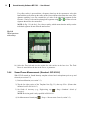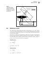
1
BE1841-14_Cover.fm Page 1 Wednesday, December 18, 2013 10:47 AM Technical Documentation Sound Intensity Software BZ-7233 For use with Hand-held Analyzer Type 2270 HEADQUARTERS: Brüel & Kjær Sound & Vibration Measurement A/S · DK-2850 Nærum · Denmark Telephone: +45 7741 2000 · Fax: +45 4580 1405 · www.bksv.com · [email protected] Local representatives and service organisations worldwide ËBE-1841---ÉÎ User Manual English BE 1841–14 Sound Intensity Software BZ-7233 For use with Hand-held Analyzer Type 2270 User Manual BE 184114 December 2013 Safety Considerations This apparatus has been designed and tested in accordance with IEC/EN 61010 – 1 and ANSI/UL 61010 – 1 Safety Requirements for Electrical Equipment for Measurement, Control and Laboratory Use. This manual contains information and warnings which must be followed to ensure safe operation and to retain the apparatus in safe condition. Special note should be made of the following: Safety Symbols The apparatus will be marked with this symbol when it is important that you refer to the associated warning statements given in the manual. Protective Earth Terminal Hazardous Voltage Explosion Hazard The equipment is not designed to be used in potentially explosive environments. It should not be operated in the presence of flammable liquids or gases. Warnings • • • Switch off all power to equipment before connecting or disconnecting their digital interface. Failure to do so could damage the equipment Whenever it is likely that the correct function or operating safety of the apparatus has been impaired, it must be made inoperative and be secured against unintended operation Any adjustment, maintenance and repair of the open apparatus under voltage must be avoided as far as possible and, if unavoidable, must be carried out only by trained service personnel • Do not dispose of electronic equipment or batteries as unsorted municipal waste • It is your responsibility to contribute to a clean and healthy environment by using the appropriate local return and collection systems • Hazardous substances in electronic equipment or batteries may have detrimental effects on the environment and human health • The symbol shown to the left indicates that separate collection systems must be used for any discarded equipment or batteries marked with that symbol • Waste electrical and electronic equipment or batteries may be returned to your local Brüel & Kjær representative or to Brüel & Kjær Headquarters for disposal Trademarks Microsoft and Windows, Vista and Excel are registered trademarks of Microsoft Corporation. Pentium is a trademark of the Intel Corporation. Copyright 2013, Brüel & Kjær Sound & Vibration Measurement A/S All rights reserved. No part of this publication may be reproduced or distributed in any form, or by any means, without prior written consent from Brüel & Kjær Sound & Vibration Measurement A/S, Nærum, Denmark Contents CHAPTER 1 Introduction......................................................................................................... 1 1.1 1.2 Welcome .............................................................................................................. 1 How to Use this Manual ....................................................................................... 1 CHAPTER 2 Concept and Contents of Type 2270-G ............................................................ 3 2.1 2.2 Sound Intensity .................................................................................................... 3 Type 2270-G Overview ........................................................................................ 4 CHAPTER 3 Setting up the Analyzer...................................................................................... 7 3.1 3.2 3.3 3.4 Connecting the Microphones to the Analyzer ...................................................... 7 Setting up Type 2270-G..................................................................................... 10 Calibration.......................................................................................................... 13 Tutorials ............................................................................................................. 22 CHAPTER 4 Measuring.......................................................................................................... 39 4.1 4.2 4.3 4.4 4.5 4.6 Measurement Control ........................................................................................ Displaying Measurement Parameters................................................................ Aural Feedback.................................................................................................. Validation ........................................................................................................... Temporal Variability ........................................................................................... Compass............................................................................................................ 39 41 49 51 52 52 CHAPTER 5 Viewing Results ................................................................................................ 55 5.1 5.2 5.3 5.4 5.5 Displaying Result Parameters............................................................................ Examine Results ................................................................................................ Validation ........................................................................................................... Creating New Projects Based on Recalled Projects .......................................... Exporting, Post-processing and Reporting ........................................................ 55 60 64 64 65 CHAPTER 6 Theory and Practice ......................................................................................... 67 6.1 6.2 6.3 6.4 6.5 6.6 6.7 Sound Pressure and Sound Power.................................................................... What is Sound Intensity? ................................................................................... Why Measure Sound Intensity? ......................................................................... Sound Fields ...................................................................................................... Particle Velocity ................................................................................................. How is Sound Intensity Measured? ................................................................... The Measuring System ...................................................................................... 67 67 68 68 70 70 71 6.8 6.9 6.10 6.11 6.12 6.13 6.14 6.15 6.16 Reference Levels ............................................................................................... Pressure-intensity Index .................................................................................... Pressure-residual Intensity Index....................................................................... Dynamic Capability ............................................................................................ Measurement Limitations................................................................................... Using Sound Intensity to Determine Sound Power............................................ Spatial Averaging............................................................................................... What about Background Noise? ........................................................................ Using Sound Power Standards.......................................................................... 73 74 74 75 75 84 84 85 87 CHAPTER 7 Specifications ................................................................................................. 103 APPENDIX A Setup Parameters ........................................................................................... 111 A.1 A.2 A.3 A.4 A.5 A.6 A.7 A.8 A.9 Input, Range Setting (Auto Range), Spacer and Transducer ................................................................................................ 111 Standard .......................................................................................................... 112 Bandwidth ........................................................................................................ 113 Measurement Control: Measurement Mode, Preset Time, Segment Order, Auto Save ............................................................................................. 113 Surface: Dimensions........................................................................................ 114 Units................................................................................................................. 115 Output Socket Signal ....................................................................................... 115 Headphone Signal ........................................................................................... 116 Generator......................................................................................................... 116 APPENDIX B Measurement and Calculated Parameters ................................................... 117 B.1 B.2 Measurement Parameters ............................................................................... 117 Calculated Parameters .................................................................................... 117 INDEX ................................................................................................................. 121 1 Chapter 1 Introduction 1.1 Welcome Sound Intensity Software BZ-7233 is one of the many application packages available for Hand-held Analyzer Type 2270. If you are newcomer to Hand-held Analyzer Type 2270, you are strongly advised to study the User Manual for Hand-held Analyzers Types 2250 and 2270 (BE 1713) before reading this manual. Studying the User Manual for Hand-held Analyzers Types 2250 and 2270 will enable a better understanding of the platform concept and how the BZ-7233 application fits into the portfolio of available options. You will also become familiar with some terms used in this manual that apply to Type 2270 in general. This manual details Type 2270 for sound intensity measurements, how to measure sound intensity and how to evaluate results. Anything not pertaining to BZ-7233 will be found in the User Manual for Hand-held Analyzers Types 2250 and 2270 (BE 1713). This manual assumes that you are familiar with the concepts of measuring sound using a microphone and some form of sound level meter/analyzer. 1.2 How to Use this Manual 1.2.1 Conventions Used in this Manual Instructions and descriptions that refer to Type 2270 pushbuttons are shown with the pushbutton icons as seen on the instrument. Icons, Buttons and Tabs Used on the Screen Indicated by bold type face (for example, tap the Main Menu icon). Parameter Text Appearing on the Screen Parameters, instructions and descriptions appearing on the screen are indicated by italics (for example, Measurement Mode). 2 Sound Intensity Software BZ-7233 – User Manual Path Denotations Indicated by capitals (for example, SETUP\BZ7222\). Menu/Screen Navigation Indicated by italics (for example, Setup > Frequency Settings > BB Peak). 1.2.2 Beginner Users of Acoustic Measurement Equipment Before you read the rest of this manual, read Brüel & Kjær’s primer on Measuring Sound. The Primer will give you a basic idea of acoustic measurements. It can be found on the www.bksv.com Web site, by typing ‘Primer’ in the search window. The Web site also contains other information you might find useful. To best understand the concepts and terms related to sound intensity, it is also recommended to read Chapter 6. Further information is available in the On-line Help installed on Type 2270. 1.2.3 Experienced Users of Acoustic Measurement Equipment The manual is designed so that you do not have to read all of it to be able to use the instrument. It is built around the most frequently used operations, which are as follows: • A brief introduction to sound intensity and Type 2270-G (Chapter 2) • Preparing the Analyzer for measurements: Mounting microphones, setting analyzer parameters, calibration and tutorials (Chapter 3) • Making measurements: Measurement control, display measured parameters, feedback validation and creating new projects from recalled projects (Chapter 4) • Results: Display result parameters, map data, validate, recall projects, exporting, postprocessing and reporting (Chapter 5) • A thorough background in the theory and practice of sound intensity (Chapter 6) • Specifications (Chapter 7) • Setup Parameters (Appendix A) • Measurement and Calculated Parameters (Appendix B) It is recommended that you read the entire manual for appropriate procedures on how to use Type 2270 and obtain accurate results. 3 Chapter 2 Concept and Contents of Type 2270-G 2.1 Sound Intensity In simple terms, sound pressure is what a person hears in a given area. Sound pressure is the result of sound power being influenced by environment at the moment of measurement. Sound power is the rate of the energy emitted from the sound source and sound intensity is a timeaveraged vector-quantity rate of energy flow per unit area. And as it is time averaged, it allows for cases where energy is travelling back and forth and cancelling itself out; i.e., if there is no net energy flow, there can be no net intensity (however, in this case there will be a reactive intensity, which is described in section 6.4.3). 2.1.1 Why Measure Sound Intensity? One application is workplace noise control. On the factory floor sound pressure measurements can determine if the workers risk hearing damage and if the noise should be reduced. To reduce the noise, we need to know how much noise is being radiated and by what machine. Therefore the sound power of the individual machines must be known and then ranked by their sound power. Once located, the noise sources of the machine making the most noise can be measured to locate the individual components radiating noise. Sound power can be derived from sound pressure only under carefully controlled conditions where special assumptions are made about the sound field. Specially constructed rooms such as anechoic or reverberant chambers fulfil these requirements, but the noise source must be placed in these rooms to calculate sound power, which may have been logistically impossible or cost prohibitive. All this can be done in situ with intensity measurements. In situ measurement with Type 2270-G can provide the necessary information to determine a course of action for complying with appropriate local and international standards and requirements. 4 Sound Intensity Software BZ-7233 – User Manual 2.2 Type 2270-G Overview Hand-held Sound Intensity System Type 2270-G is a powerful combination of Hand-held Analyzer Type 2270, Sound Intensity Software BZ-7233 and Sound Intensity Probe Kit Type 3654 and enables intensity measurements for noise source location and sound power calculations. Automatic measurement guidance and aural feedback during measurements allow smooth scans of the area under investigation. The system also provides on-the-spot analyses of sound intensity spectra and calculation of sound power. Results can be exported via Measurement Partner Suite BZ-5503 to Excel® for further calculation and reporting or to PULSE™ Noise Source Identification Type 7752 for noise contour mapping. The system is part of the Type 2270 hand-held platform, which has a vast range of sound and vibration analysis applications. Fig.2.1 Hand-held Sound Intensity System Type 2270-G CHAPTER 2 Concept and Contents of Type 2270-G Fig.2.2 Hand-held Sound Intensity System Type 2270-G (included items) QA-0236 Tape Measure KE-0458 Carrying Case DP-0888 Intensity Adaptor for 4231 HT-0015 Earphones 10-pin UA-0781 Ellipsoidal Windscreen 4197 Sound Intensity Microphone Pair 2683 Dual Preamplifier 10-pin BZ-7233 Sound Intensity Software 10-pin 10-pin UA-1439 Extension Stem 10-pin UA-1440 Handle with Integral Cable 2270 Hand-held Analyzer including 4189 Microphone ZE-0032 Microphone Preamplifier 100129/1 5 6 Sound Intensity Software BZ-7233 – User Manual CHAPTER 3 Setting up the Analyzer 7 Chapter 3 Setting up the Analyzer 3.1 Connecting the Microphones to the Analyzer 3.1.1 Mounting the Microphones NOTE: Before mounting the microphones, please observe the following precautions: • Do not touch the microphone diaphragm with anything – it is very delicate • Gently screw on the microphones to avoid damaging the threads • Keep dust and foreign matter off the microphone diaphragm The microphones normally used with this software are the phase matched 1/2 Sound Intensity Microphone Pair Type 4197, which require an external polarization voltage of 200 V. To mount a microphone pair: 1) Identify Microphone Type 4197 Part1 and Part2, tube connected to cable A and cable B and the compression joints (Fig. 3.1) Fig. 3.1 1. Microphone part numbers, 2. Cables A and B, 3. Compression joints 1 2) Loosen the bottom compression joint screw and gently retract the bottom tube (connected to the cable marked B). 3) Gently screw Microphone Type 4197 Part2 onto the bottom tube. 4) Select the desired spacer (for more information in spacer selection, see section 6.9.7) and gently screw the side of the spacer with the metal insert onto Microphone Type 4187 Part1. 5) Gently screw Microphone Type 4187 Part1 onto the top tube (connected to cable A). 8 Sound Intensity Software BZ-7233 – User Manual 6) Slightly loosen the compression joint for the top tube so that the tube can twist. 7) Gently push the bottom tube towards Microphone Type 4187 Part1 (twisting the top tube as necessary to align the microphone pair) until the nib on the end of Type 4187 Part2 slots into the hole on the spacer. The general position of the tubes should as shown in Fig. 3.2. 8) Tighten both compression joints. 3.1.2 Conecting the Probe to the Analyzer NOTE: Do not mount the probe directly onto the Analyzer. If you do so by mistake, you will need to remove it by gently prising the probe out with a small screwdriver. The probe should be mounted onto the Extension Stem UA-1439, which is attached to the Handle with Integral Cable UA-1440, which is then connected to the Analyzer. 3.1.3 Mounting the Probe onto the Handle The probe can be connected directly to the handle if necessary (i.e., space considerations), but because it is difficult to remove, this is not recommended. To mount the probe onto the handle, simply insert the probe plug into the input socket of the handle, making sure it snaps into position 3.1.4 Mounting the Probe onto the Extension Stem To mount the probe onto the extension stem, insert the LEMO connector at the bottom of the probe into the socket of the extension stem, pressing gently (rotating if necessary to correctly align the LEMO connectors) until it snaps into position. Push the securing sleeve up and screw the sleeve into position (Fig. 3.2). CHAPTER 3 Setting up the Analyzer 9 Fig. 3.2 The probe in position on the extension stem 3.1.5 Mounting the Extension Stem onto the Handle Insert the probe plug into the input socket at the top of the handle. Push into position and secure by turning the threaded securing sleeve. 3.1.6 Removing the Probe from the Handle or Extension Stem To remove the probe from the handle, slide back the locking ring and gently pull out the probe. When removing the probe from the extension stem, unscrew the threaded securing sleeve, slide back the locking ring and gently pull out the probe. 10 Sound Intensity Software BZ-7233 – User Manual 3.2 Setting up Type 2270-G To set up Type 2270 for the Sound Intensity Project Template: 1) Select the SOUND INTENSITY Project Template. (see section 3.3.1 of Hand-held Analyzers Types 2250 and 2270 – User Manual for more details on templates.) The Project Template is displayed on the black banner at the top of the screen (see Fig. 3.3). If this banner does not display SOUND INTENSITY, tap on the banner and select SOUND INTENSITY from the drop-down menu and then select Open from the subsequent dropdown menu. Fig. 3.3 Template line displaying: a. Template, b. Standard and c. SI Task a. b. c. 2) Measurements can be stored on the internal disk, or as an optional storage method, insert an SD card in the SD Card slot, a USB memory stick in the USB Standard A slot (hardware version 4 only) or CF card in the CF card slot (hardware versions 1 – 3 only). The slots are located on the connector panel described in Hand-held Analyzers Types 2250 and 2270 – User Manual. You will be notified that a memory card has been inserted – select Yes to change the default measurement path to the memory card. 3) Tap the Main Menu icon and select Explorer. Create a job folder for the measurements and set the default measurement job/path as described in Chapter 6 of Hand-held Analyzers Types 2250 and 2270 – User Manual. 4) Tap and select Setup. The Setup screen, Full tab will appear, see Fig. 3.4. Fig. 3.4 The SETUP screen See Appendix A for details on the setup parameters CHAPTER 3 Setting up the Analyzer 11 5) Set Input: – Input: Top Socket – Range Setting: Low Range or High Range NOTE: Pressing before a measurement institutes Auto Range, which automatically selects High or Low range, as appropriate – Spacer: Between 6 and 200 mm (12 mm is recommended) – Input Ch.1: Enter the microphone pair being used and specify Windscreen Correction if applicable NOTE: Selecting a microphone pair for Input Ch.1 will apply the same settings to Input Ch.2 NOTE: 1/4” microphones will need to be individually input If the microphone pair does not appear in the list, they must be defined: a) Tap and select Transducers. b) Tap the New Transducer icon and select Microphone Pair. The microphone pair is then created as 4197_P1 (0) and 4197_P2 (0) and automatically selected as input for Ch. 1 and Ch. 2. c) Tap on 4197_P1 (0) to open it. d) If the microphone pair is a Type 4181 pair, tap on Microphone Type and select 4181. e) Tap Serial No. and insert serial number of the microphone pair. f) Tap when finished. g) Tap Preamplifier ID No. and insert serial number of the preamplifier. h) Tap when finished. You should now have a screen like Fig. 3.5. Fig. 3.5 Transducer input screen 12 Sound Intensity Software BZ-7233 – User Manual 6) Set Standard (see section 6.16): None, ISO 9614–1, ISO 9614–2, ANSI S12.12 or ECMA 160 7) Set Bandwidth: – Bandwidth: 1/1-octave or 1/3-octave 8) Set Measurement Control: – SI Task: Sound Power/Mapping, Temp. Variability or Compass – Measurement Mode: Manual or Automatic – Preset Time: Enter time – Segment Order: Select measurement pattern from drop-down list – Automatic Save: Yes or No 9) Set Surface: – Total Surface Type: Box (the number or surfaces will be set to five, prearranged in the Box pattern) or Custom (the number of surfaces can be user-defined) – Selected Surface: Individual surface parameters (Surface Name, Surface Height, Rows, Columns, Segment Height and Segment Width) are valid for the selected surface – Surface Name: Enter a name for the selected surface – Surface Height: Enter the total height for the area to be measured. (This will autopopulate if Rows and then Segment Height were stipulated.) – Surface Width: Enter the total width for the area to be measured. (This will autopopulate if Columns and then Segment Width were stipulated.) – Rows: Enter the number of rows into which the total height will be segmented – Columns: Enter the number of columns into which the total height will be segmented – Segment Height: Enter the height of the individual segments. (This will auto-populate if Rows and then Surface Height were stipulated.) – Segment Width: Enter the width of the individual segments. (This will auto-populate if Columns and then Surface Width were stipulated.) Repeat specifying individual surface parameters for each surface. NOTE: You can set Height and Width in metres (SI) or feet (US/UK) – set in Preferences > Regional Settings > Dimension Unit. 10) Set Signal Recording (requires license for Signal Recording Option BZ-7226): NOTE: You can record the signal in a 2-channel .WAV file for further analysis using Brüel & Kjær’s PULSE™ Multi-analyzer platform or just for listening and validation purposes. – Recording Mode: Off or Automatic for recording during the measurement. – Recording Quality: High (20 kHz), Medium (10 kHz), Fair (6.6 kHz) or Low (3.3 kHz) in accordance with your needs. NOTE: High quality requires more disk space than low quality – see details in Specifications – Resolution: 16 or 24 bit CHAPTER 3 Setting up the Analyzer 13 NOTE: 24 bit at High (20 kHz) recording quality is not available for hardware versions 1 – 3 11) Set Output Socket Signal: – Source: Off, Intensity, AF, Intensity, CF, Intensity, ZF or Generator If Generator is selected Generator settings will be available – Lowest Level (= 0 V) (only availible if Source is set to Intensity, AF, CF or ZF): From – 20 to 160 dB 12) Set Headphone Signal: – Aural Feedback: Off or On – Aural Feedback Gain: Enter the + or – dB for headphone volume 13) Set Generator: – Noise Type: White or Pink – Level[re. 1 V]: From –80.0 to 0.0 (use number pad or the arrows (up/down)) – Bottom Frequency: Incrementally from 50 Hz to 10 kHz – Top Frequency: Incrementally from 50 Hz to 10 kHz 14) To exit the screen, tap the Close icon . 3.3 Calibration 3.3.1 Using Type 4297 for Sound Pressure and Phase Calibration To calibrate the microphone pair using Sound Intensity Calibrator Type 4297: 1) Place the calibrator on a clean, flat surface. Lift the upper half to a near vertical position, as shown in Fig. 3.6 (to open the unit, lift the black handle into the vertical position and turn it counterclockwise) and remove the protection plug. This exposes the intensity probe holder and the black plastic button that gives access to the battery compartment. 14 Sound Intensity Software BZ-7233 – User Manual Fig. 3.6 The unit is open and ready to receive the sound intensity probe 2) Place the Sound Intensity Probe into the holder (Fig. 3.7). Fig. 3.7 Sound Intensity Probe in holder CHAPTER 3 Setting up the Analyzer 15 NOTE: For best results, the spacer should be removed. But the spacer should be used to set the correct distance by placing it between the microphone pair without screwing in the spacer (see Fig. 3.8.), tightening the compression joint to hold the slider in place and then removing the spacer for placement into the calibrator. Fig. 3.8 Spacer as a guide 3) Close the unit by reversing the procedure described above. Sound Pressure Level Calibration Type 2270-G is now ready for sound pressure calibration. NOTE: Minimise vibrations at your work surface/equipment during calibration as vibrations will falsely affect readings. 1) With the sound intensity probe connected to Type 2270-G, switch on the Analyzer and select Sound Intensity Project Template. 2) Ensure that the Analyzer is properly set up for calibration with the calibrator to be used. a) Tap and select Setup. b) Expand Input by tapping it and ensure that the Input line reads Top Socket and that the Spacer line reads 12 mm. c) Tap and select Transducers. If the transducers are not in the system, see section 3.2, step 5) Set Input: for instructions on entering a new microphone pair. 3) Tap and select Calibration. The Calibration screen will appear (Fig. 3.9). 16 Sound Intensity Software BZ-7233 – User Manual Fig. 3.9 Calibration screen 4) On the Details tab: a) Tap Calibrator, select 4297. b) Tap Calibration level and enter 94 dB. 5) On the Level tab: a) Tap Ambient Temperature and enter the current temperature. NOTE: You can set temperature to Celsius (SI) or Fahrenheit (US/UK) – set in Preferences > Regional Settings > Temperature Unit. b) Tap Ambient Pressure and enter the current barometric pressure. 6) Press the Start button on the Type 4297 control panel (see Fig. 3.10). The sine wave (251.2 Hz) LED indicator should light. If it does not, the batteries need to be replaced, as described in Chapter 1 of the Sound Intensity Calibrator Type 4297 – User Manual. CHAPTER 3 Setting up the Analyzer 17 Fig. 3.10 Type 4297 control panel showing the start, sine wave/broadband noise selector buttons and LED indicators NOTE: If a sound intensity probe is not placed in the chamber, the unit will shut down after approximately 10 seconds. 7) Allow at least 5 seconds for the pressure to equalise and for stabilisation of the feedback circuit. 8) Tap Calibrate and wait for it to finish. Phase Calibration and Pressure-Residual Intensity Index Verification Phase calibration and pressure-residual intensity index verification are part of the complete calibration process and should follow after sound pressure level calibration; however, they can also be performed individually. If calibrating and verifying phase by itself, perform steps 1) through 5) and then continue from step 9). NOTE: Minimise vibrations at your work surface/equipment during calibration as vibrations will falsely affect readings. 9) Tap on the Phase tab at the bottom of the screen and the Phase calibration screen will appear (Fig. 3.11). 18 Sound Intensity Software BZ-7233 – User Manual Fig. 3.11 Phase Calibration screen 10) Tap Calibrate and wait for it to finish. NOTE: Tapping Calibrate includes the verification process, but verification can be performed individually. To do so, tap Verify and let the verification continue for 2 minutes and press Stop Verify. 11) Tap Yes to accept the new calibration (and verification). There should be no yellow smileys. 12) Turn off the calibrator, remove the probe, insert the protection plug and close the calibrator. NOTE: The frequency range for the calibrators does not include the 8 and 10 kHz bands. Results shown from these bands are extrapolated from the 6.3 kHz band. 3.3.2 Using Type 3541 for Sound Pressure and Phase Calibration For full details on the use of this calibrator, please refer to Sound Intensity Calibrator Type 3541 – User Manual (BE 1024-12) or Sound Intensity Calibrator Type 3541-A – User Manual (BE 1024 version 13 or later). NOTE: Type 3541-A does not support phase calibration because it does not contain Sound Source ZI-0055. Sound Pressure Level Calibration To calibrate the sound pressure sensitivity of the microphone channels: 1) Switch on the Analyzer and select Sound Intensity Project Template. 2) Ensure that the Analyzer is properly set up for calibration with the calibrator to be used. a) Tap and select Setup. b) Expand Input by tapping it and ensure that the Input line reads Top Socket and that the Spacer line reads 12 mm. c) Tap and select Transducers. CHAPTER 3 Setting up the Analyzer 19 If the transducers are not in the system, see section 3.2, step 5) Set Input: for instructions on entering a new microphone pair. 3) Tap and select Calibration. The Calibration screen will appear (Fig. 3.9). 4) On the Details tab: a) Tap Calibrator, select 3541 b) Tap Calibration level and enter the sound pressure level from the Type 3541 calibration chart. Type 2270 will automatically correct the calibration level for the ambient pressure during the calibration. 5) On the Level tab: a) Tap Ambient Temperature and enter the current temperature. NOTE: You can set temperature to Celsius (SI) or Fahrenheit (US/UK) – set in Preferences > Regional Settings > Temperature Unit. b) Tap Ambient Pressure and enter the current barometric pressure. 6) Screw the intensity coupler onto its base. 7) Insert the dummy microphone into port 3. 8) Insert one microphone into port 1 and one into port 2. 9) Place the pistonphone on the intensity coupler. The pistonphone, intensity coupler and microphones should now be arranged as shown in Fig.3.12. NOTE: This is a very tight fit. Press firmly and ensure that the microphones are fully seated to avoid erroneous results. Fig.3.12 Arrangement for sound pressure calibration 20 Sound Intensity Software BZ-7233 – User Manual NOTE: Do not place the coupler in a warm area, for example on top of measuring equipment, as heat affects calibrations. 10) Set up Type 2270 for sound pressure level calibration. 11) Switch on the pistonphone. 12) Tap Calibrate and wait for it to finish. 13) Switch off the pistonphone 14) Remove the pistonphone from the top of the coupler. Phase Calibration and Verification Phase calibration and pressure-residual intensity index verification are part of the complete calibration process and should follow after sound pressure level calibration; however, they can also be performed individually. If calibrating and verifying phase by itself, perform steps 1) through 8) and then continue from step 15). 15) Mount Sound Source ZI-0055 on top of the coupler. 16) Switch on the sound source. 17) Tap on the Phase tab at the bottom of the screen and the Phase calibration screen will appear (Fig. 3.11). 18) Tap Calibrate and wait for it to finish. NOTE: Tapping Calibrate includes the verification process, but verification can be performed individually. To do so, tap Verify and let the verification continue for 2 minutes and press Stop Verify. 19) Tap Yes to accept the new calibration (and verification). There should be no yellow smileys. 20) Switch off the sound source. 3.3.3 Using Type 4231 For full details on the use of this calibrator, please refer to Sound Calibrator Type 4231 – User Manual (BA 5341) Sound Pressure Level Calibration. 1) Select the correct adaptor for the microphone diameter you want to calibrate and fit it to the calibrator (see Table 1.1 of Sound Calibrator Type 4231 – User Manual). 2) Switch on the Analyzer and select the Sound Intensity Project Template. 3) Ensure that the Analyzer is properly set up for calibration with the calibrator to be used. a) Tap and select Setup. b) Expand Input by tapping it and ensure that the Input line reads Top Socket and that the Spacer line reads 12 mm. CHAPTER 3 Setting up the Analyzer c) Tap 21 and select Transducers. If the transducers are not in the system, see section 3.2, step 5) Set Input: for instructions on entering a new microphone pair. 4) Tap and select Calibration from the list of options. The Calibration screen will appear (Fig. 3.9). 5) On the Details tab: a) Tap Calibrator, select 4231 6) On the Level tab: a) Tap Ambient Temperature and enter the current temperature. NOTE: You can set temperature to Celsius (SI) or Fahrenheit (US/UK) – set in Preferences > Regional Settings > Temperature Unit. b) Tap Ambient Pressure and enter the current barometric pressure. 7) Insert microphone pair Part2 (cable B/channel 2) into the Type 4231 – slightly loosen the compression joints for both tubes so that the Channel 2 tube can be pushed forward and the Channel 1 tube can be pulled back and twisted out of the way (see Fig. 3.13). Fig.3.13 Single microphone arrangement 8) Press the calibrator’s On/Off button (you should be able to hear a faint tone), then tap the Calibrate button on the Type 2270 touch-screen. 9) The Analyzer will prompt you to continue when Channel 2’s level has been detected. 10) Remove microphone pair Part2 (cable B/channel 2) from the calibrator and insert it into Coupler DP-0888. 11) Insert microphone pair Part1 (cable A/channel 1) into the other side of the coupler and insert Coupler DP-0888 into the calibrator (see Fig. 3.14). 22 Sound Intensity Software BZ-7233 – User Manual Fig.3.14 Dual microphone arrangement 12) Press the calibrator’s On/Off button on the calibrator (listen for the tone). 13) Tap Continue Calibration and wait for it to finish. 14) Remove the calibrator from the microphone. 15) Switch off the calibrator, or wait for it to stop, before closing the flap on its case. 3.3.4 Field Check To check the instrumentation for proper operation prior to a series of measurements, perform a field check, as is recommended by the supported standards: 1) On the Calibration screen, tap the Check tab. 2) Place the intensity probe on the measurement plane, with the axis oriented normal to the surface. The probe should be placed at a location where the intensity is higher than the surface average. 3) Tap Start First Pass to begin the measurement. 4) Watch the spectrum and wait for it to stabilise (at least 20 s), then tap Stop First Pass. 5) Note the location of the spacer and rotate the intensity probe 180° so that the probe is pointing in the opposite direction while keeping the spacer in the same position as during the first measurement. 6) Tap Start Second Pass and wait for the measurement to finish (the second measurement will run the same number of seconds as the first measurement), or tap Stop Second Pass to end the measurement early. CHAPTER 3 Setting up the Analyzer 23 The cursor will automatically be set to the frequency band with the highest level, which is checked against the limit. NOTE: Mounting the intensity probe on a stand makes it much easier to maintain the same spacer position when rotating the probe. The result of the field check is not stored together with a job. 3.4 Tutorials 3.4.1 Description of the Measurement and Result Displays The display views are divided into: • Measurement displays for usage during measurement • Result displays for studying the results The Measurement displays are dependant on the SI Task (selected in the upper right corner of the screen. For SI Task = S.Pwr (sound power/mapping), the available Measurement displays consist of: • Surface: Displays measurements in segments on a surface. The segments are coloured in accordance with the measurement state. • Spectrum: Displays the measured spectra during the measurement For SI Task = Temp.Variability (temporal variability), the available Measurement display is: • Spectrum: Displays the Temporal Variability Spectrum and setting for the averaging time For SI Task = Compass, the available Measurement display is: • Compass: Useful for noise source location When opening a Sound Intensity template or project, one of the measurement views will be displayed. The Result displays consists of: • Total: Displays results from the surfaces, either as a list or as numbers in a box (for Total Surface Type = Box, only) • Surface: Displays measurement results as numbers in the segments or as Curve or Contour maps • Spectrum: Displays measurement results The Result Displays are accessed from a link on the Measurement displays (for SI Task = S.Pwr). Examples of the various displays are used in the tutorials and in chapters 4 and 5. 24 Sound Intensity Software BZ-7233 – User Manual 3.4.2 On-line Noise Source Location – Compass With 2270-G turned on and Sound Intensity template selected and a microphone pair set up: 1) Tap the far right section of the Template line (Fig. 3.3), then tap Compass. 2) Select the desired parameter (Intens., ZF or Intens., AF) and frequency (25 Hz – 10 kHz or A- or Z-weighted). Fig. 3.15 Left Compass display positive Right Compass display negative 3) Holding the microphone pair parallel with the plane of the measured surface, scan the plane and observe the motion of the speaker icon on the compass display. NOTE: The probe should be oriented the same way as the probe presented on the Compass display: either change the direction of the probe in your hand or tap the image of the probe on the Compass display, which will flip the image of the display. Three positions are available: 1) Pointing to the left, 2) probe pointing to the right and 3) probe pointing forwards. When the speaker is in front of the probe, the noise source is in front of the probe and the direction of the sound intensity is defined as positive, indicated in Fig. 3.15 Left, with the white bar graph and the + sign behind the dB in the readout. When the speaker is behind the probe, the noise source is behind and the direction of the sound intensity is defined as negative, indicated in Fig. 3.15 Right, with a coloured bar graph and a – sign behind the dB in the readout. When the speaker icon jumps rapidly back and forth on the display, the noise source is in the probe’s 90° direction (further information in Fig. 6.4). Using Aural Feedback in the headphones aids locating the noise source relative to the probe – high pitch indicates that the noise source is in front of the probe and low pitch, behind. CHAPTER 3 Setting up the Analyzer 25 Fig. 3.16 Aural Feedback setup 3.4.3 Sound Power Measurement (Standard: None) With 2270-G turned on, Sound Intensity template selected and a microphone pair set up and selected (see section 3.2): 1) Perform calibration (see section 3.3). 2) Tap the far right section of the Template line (Fig. 3.3), then tap S.Pwr. (Ensure that Standard is set to None.) 3) Set Measurement Control (tap > Setup > Measurement Control; see section 3.2). Fig. 3.17 Measurement Control setup 4) Set Surface (tap > Setup > Surface; see sections 3.2 and 4.2.2). 26 Sound Intensity Software BZ-7233 – User Manual Fig. 3.18 Surface setup For example: To set up a simple box: a) Select Total Surface Type = Box. b) Set Surface Height and Surface Width for each surface (select the surface using the Selected Surface parameter). c) For Front: set Surface Height = 1.2 m and set Surface Width = 1.5 m. d) For Left: set Surface Width = 1.6 m, Surface Height for Left is equal to Surface Width for Front. All surface dimensions are set now (Settings for Front is equal to settings for Back, Left is equal to Right and Top Surface Width is equal to Front Surface Width and Top Surface Height is equal to Left Surface Width). Fig. 3.19 Left Result >: Select Total tab and select Number instead of List in the status panel to get an overview of the box Right Hypothetical box surrounding a noise surface 5) Close the Result display, select the Spectrum tab and select Front in the status panel. CHAPTER 3 Setting up the Analyzer 27 6) Position the probe at the centre of the segment: Place the probe on the measurement plane with the axis oriented normal to the surface. Let the curved part of the probe point towards the plane, such that the acoustical centre of the probe (the middle of the spacer, not the tip of the probe) is bisected by the plane. 7) Press and measure for the full time period that was stipulated in Setup. 8) Examine the spectrum: a) If the result is satisfactory, press . b) If the result was unsatisfactory, press and remeasure the segment. 9) Select the next surface (for example, Left). Repeat steps 6), through 9) for the remainder of the measurement. 10) Tap Result >. 11) Tap Result > and select the Spectrum tab and set the Spectrum Parameters to Power, A and Tot. Pwr, A. If the A-total reading in Tot. Pwr, A does not have a smiley, there are no warnings for the calculated A-total. However, if it has a smiley, you must investigate the segment spectra or surface spectra in more detail. Fig. 3.20 Spectrum Result tab with parameters set to Power,A and Tot. Pwr,A* 12) Examine the saved data in the segments, looking for smileys in different frequencies or with A- or Z-weighting. 13) Tap Spectrum and use the display cursor to examine different frequencies for different segments and exclude or include bands to pinpoint problems. * The Tot. Pwr,A parameter is the sum of the sound power from the individual segments. 28 Sound Intensity Software BZ-7233 – User Manual If a yellow smiley is present below a frequency band, tap in the spectrum to select this band with the cursor, then tap the smiley at the cursor readout to determine the cause. If the dynamic capability is too low, examine the p-I index of the individual segments. Select Dynamic C and p-I index and step through the segments using or in order to locate segments that need to be remeasured. NOTE: In Fig. 3.21, the Surf. Pwr,A has no smiley, which means that the smileys on the individual segments do not affect the total surface. Fig. 3.21 Result spectrum with smileys 14) Select the Total tab and view the results for each surface in the box view. The Total Power is stated below the box in the Power, A parameter. 3.4.4 Sound Power Measurement (Standard: ISO 9614-2) With 2270-G turned on, Sound Intensity template selected and a microphone pair set up and selected (see section 3.2): 1) Perform calibration (see section 3.3). 2) Tap the far right section of the Template line (Fig. 3.3), then tap S.Pwr. (Ensure that Standard is set to ISO 9614-2.) 3) Set Grade of Accuracy (e.g., Engineering; tap > Setup > Standard > Grade of Accuracy). NOTE: Precision grade is only specified in ISO 9614–1. 4) Set Measurement Control (tap > Setup > Measurement Control; section 3.2). CHAPTER 3 Setting up the Analyzer 29 Fig. 3.22 Measurement Control setup 5) Set Surface (tap > Setup > Surface; see sections 3.2 and 4.2.2). Fig. 3.23 Surface setup For example: To set up a simple box: a) Select Total Surface Type = Box. b) Set Surface Height and Surface Width for each surface (select the surface using the Selected Surface parameter). c) For Front: set Surface Height = 1.2 m and set Surface Width = 1.5 m. d) For Left: set Surface Width = 1.6 m, Surface Height for Left is equal to Surface Width for Front. All surface dimensions are set now (Settings for Front is equal to settings for Back, Left is equal to Right and Top Surface Width is equal to Front Surface Width and Top Surface Height is equal to Left Surface Width). 30 Sound Intensity Software BZ-7233 – User Manual Fig. 3.24 Left Result >: Select Total tab and select Number instead of List in the status panel to get an overview of the box Right Hypothetical box surrounding a noise surface 6) Close the Result display, select the Spectrum tab and select Front in the status panel. According to ISO 9614–2, each segment must be scanned twice, and the second scan must be orthogonal to the first. Each scan must have a duration of at least 20 seconds. 7) Position the probe in one of the corners of the segment: Place the probe on the measurement plane with the axis oriented normal to the surface. Let the curved part of the probe point towards the plane, such that the acoustical centre of the probe (the middle of the spacer, not the tip of the probe) is bisected by the plane. 8) Press and listening for the Aural feedback, scan the segment in an evenly paced s-pattern, covering equal areas in equal time, for the full time period (minimum 20 seconds) that was stipulated in Setup. When the specified time period has elapsed the measurement will automatically pause and the count indication will change from 1to 2. 9) Press and listening for the Aural feedback, scan the segment in an evenly paced s-pattern, orthogonal to the s-pattern used in step 8), covering equal areas in equal time, for the full time period (minimum 20 seconds) that was stipulated in Setup. When the specified time period has elapsed the measurement will automatically pause. 10) Examine the spectrum: a) If the result is satisfactory, press . b) If the result was unsatisfactory, press and remeasure the segment. NOTE: If you have Repeatability failed smileys at important frequency bands, you might need to redo both scans. Refer to section 6.16.6 for more hints on what to do if there is a “repeatability failed” or other smiley. 11) Select the next surface (for example, Left). Repeat steps 7), through 11) for the remainder of the measurement. 12) Tap Result > and select the Spectrum tab and set the Spectrum Parameters to Power, A and Tot. Pwr, A. If the A-total reading in Tot. Pwr, A does not have a smiley, there are no warnings for the CHAPTER 3 Setting up the Analyzer 31 calculated A-total. However, if it has a smiley, you must investigate the segment spectra or surface spectra in more detail. Fig. 3.25 Spectrum Result tab with parameters set to Power,A and Tot. Pwr,A* 13) Examine the saved data in the segments, looking for smileys in different frequencies or with A- or Z-weighting. 14) Tap Spectrum and use the display cursor to examine different frequencies for different segments and exclude or include bands to pinpoint problems. If a yellow smiley is present below a frequency band, tap in the spectrum to select this band with the cursor, then tap the smiley at the cursor readout to determine the cause. If the dynamic capability is too low, examine the p-I index of the individual segments. Select Dynamic C and p-I index and step through the segments using or in order to locate segments that need to be remeasured. NOTE: In Fig. 3.21, the Tot. Pwr, A has no smiley, which means that the smileys on the individual segments do not affect the total surface. * The Tot. Pwr,A parameter is the sum of the sound power from the individual segments. 32 Sound Intensity Software BZ-7233 – User Manual Fig. 3.26 Result spectrum with smileys See section 6.16.2 for more information on measuring with this standard. 3.4.5 Sound Power Measurement (Standard: ANSI S12.12) With 2270-G turned on, Sound Intensity template selected and a microphone pair set up and selected (see section 3.2): 1) Perform calibration (see section 3.3). 2) Tap the far right section of the Template line (Fig. 3.3), then tap S.Pwr. (Ensure that Standard is set to ANSI S12.12.) 3) Set Grade of Accuracy as requested (e.g., Engineering; tap Grade of Accuracy). 4) Set Measurement Control (tap Fig. 3.27 Measurement Control setup > Setup > Standard > > Setup > Measurement Control; see section 3.2). CHAPTER 3 Setting up the Analyzer 5) Set Surface (tap 33 > Setup > Surface; see sections 3.2 and 4.2.2). Fig. 3.28 Surface setup According to ANSI S12.12, two measurement surfaces must be defined around the source under test, one divided into N/2 segments, the other divided into N segments (N To set up a simple surface two rows and two columns: a) Select Total Surface Type = Custom. b) Set Surface Height = 1 m and set Surface Width = 1 m. c) Fig. 3.29 Left: Pop-up dialog Right: Adjust setting options Set Rows N/2 = 2 and Columns N/2 = 2. Tapping the parameter to the right of each brings up the pop-up dialog shown in Fig. 3.29. To set the number place the check in the checkbox for Adjust setting and tap OK. 34 Sound Intensity Software BZ-7233 – User Manual d) To set the N value to double Columns, tap the parameter to the right of Double no. of Columns to bring up the pop-up dialog shown in Fig. 3.30, place the check in the checkbox for Adjust setting and tap OK. e) Select Columns: The N value for Columns will be set to 4. Fig. 3.30 Left: Pop-up dialog Right: Adjust setting options All surface dimensions are now set. 6) Perform a measurement at each segment of the two surfaces. 7) Position the probe at the center of the segment: Place the probe on the measurement plane with the axis oriented normal to the surface. Let the curved part of the probe point towards the plane, such that the acoustical centre of the probe (the middle of the spacer, not the tip of the probe) is bisected by the plane. NOTE: As an alternative to this meathod, scanning can be used. 8) Press and measure for the full time period that was stipulated in Setup. When the specified time period has elapsed the measurement will automatically pause. For the required time period, see section 6.16.4. 9) Examine the spectrum: a) If the result is satisfactory, press . b) If the result was unsatisfactory, press 10) Pressing or and remeasure the segment. automatically selects the next segment in the series for measurement. Repeat steps 6), through 8) for the remainder of the measurement. 11) Tap Result > and select the Spectrum tab and set the Spectrum Parameters to Power, A and Tot. Pwr, A. If the A-total reading in Tot. Pwr, A does not have a smiley, there are no warnings for the calculated A-total. However, if it has a smiley, you must investigate the segment spectra or surface spectra in more detail. CHAPTER 3 Setting up the Analyzer 35 Fig. 3.31 Spectrum Result tab with parameters set to Power,A and Tot. Pwr,A* 12) Examine the saved data in the segments, looking for smileys in different frequencies or with A- or Z-weighting. 13) Tap Spectrum and use the display cursor to examine different frequencies for different segments and exclude or include bands to pinpoint problems. If a yellow smiley is present below a frequency band, tap in the spectrum to select this band with the cursor, then tap the smiley at the cursor readout to determine the cause. If the dynamic capability is too low, examine the p-I index of the individual segments. Select Dynamic C and p-I index and step through the segments using or in order to locate segments that need to be remeasured. NOTE: In Fig. 3.21, the Tot. Pwr,A has no smiley, which means that the smileys on the individual segments do not affect the total surface. Fig. 3.32 Result spectrum with smileys * The Tot. Pwr,A parameter is the sum of the sound power from the individual segments. 36 Sound Intensity Software BZ-7233 – User Manual If there is a problem with the Convergence index failed smiley according to step 13), double N and remeasure by: 14) Tap > Setup > Surface and select Rows N/2, Columns N/2 or Double no. of to bring up the pop-up dialog shown in Fig. 3.33. Fig. 3.33 Left: Pop-up dialog Right: Adjust setting options 15) Place the check in the checkbox for Double number of Columns and tap OK to bring up the dialog in Fig. 3.33 Right and tap OK to confirm. Rows will remain the same, but the N/2 value and N value for Columns will be set to 4 and 8, respectively. All surface dimensions are now set. 16) Repeat the measurement process until the measurement is satisfactory. See section 6.16.4 for more information on measuring with this standard. 3.4.6 Images With Type 2270-G turned on and Sound Intensity template selected: 1) Navigate to the Surface tab. 2) Tap on 3) Tap on (at the bottom left of the Surface display). . (ensure that the image conforms to the measurement surface). 4) Press to capture the image. 5) Press to save the image or to reject the image and capture the image again. 6) Tap the image and tap Select for Surface to place the image as the surface background. 7) Tap and drag the stylus across the image to crop image that will be measured to the defined surface. CHAPTER 3 Setting up the Analyzer 3.4.7 37 Mapping Measurement With Type 2270-G turned on, Sound Intensity template selected and transducers set up and selected (see section 3.2): 1) Perform calibration (see section 3.3). 2) Set SI Task to S.Pwr then set the standard to None. 3) Set Measurement Control (tap > Setup > Measurement Control; see section 3.2). Fig. 3.34 Measurement Control setup 4) Set Surface (tap > Setup > Surface; see sections 3.2 and 4.2.2). Fig. 3.35 Surface setup 5) Tap to exit Setup. 6) Apply an image, if desired (see section 3.4.6). 38 Sound Intensity Software BZ-7233 – User Manual 7) Tap Surface tab. 8) Beginning with the segment indicated on the Surface display, position the probe to measure from the centre of the segment. 9) Press and hold the probe in the centre of the segment for the full time period that was stipulated in Setup. 10) Data are auto saved, and the segment selector is positioned on the next segment. 11) Follow the segment measurement path stipulated in Setup for the remainder of the measurement. See Fig. 3.36. Fig. 3.36 Left Three measurements have been made, you are ready to measure at segment R1, C4 Right You are measuring at R1, C4 – the segment has turned green. When paused it turns yellow, and when saved, it turns blue and the position moves to next segment Bottom R1, C5 ready for measurement 12) Tap Result >. CHAPTER 3 Setting up the Analyzer 39 13) Examine the saved data in the segments, select to display A-weighted total from Power,A, which gives a good overview of the data. If a smiley appears at a frequency, it will also appear in the A-weighted total. In Fig. 3.37, Left, there is only a single smiley at R1, C3. Tap at the smiley in the line above the surface to display the problem. In this case the dynamic capability is too low (see Fig. 3.37, Right). 14) Display using Contour and Curve maps and show maxima. Fig. 3.37 Left Quality indicator: Smiley in segment R1, C3 Right Smiley description 15) Tap Spectrum to display the spectrum at R1, C3. Note that the dynamic capability is too low for 80 Hz only in this segment. Because it does not have any effect on the Power for the surface, there is no smiley for the Surf.Pwr,A readout (Fig. 3.38). Fig. 3.38 Spectrum view with smiley on Power,A 40 Sound Intensity Software BZ-7233 – User Manual 39 Chapter 4 Measuring 4.1 Measurement Control The stylus and navigation pushbuttons are used for setting up the analyzer, navigating through the screens and managing the results. A number of items that appear on the screen (parameter values or icons) can be selected, updated and activated. For instance, a new parameter value can be selected from a drop-down list. The selection and activation of items on the screen can be done in two ways: 1) Tapping once on the item on the screen will select and activate it. 2) Moving the field selector around using the navigation keys until the item you want is highlighted, then pressing the Accept pushbutton to activate it. You can choose to use the stylus or the pushbuttons, depending on your preference and the measurement situation. 4.1.1 Use of Pushbuttons for Controlling Measurements The design of the analyzer is such that the layout of the pushbuttons has been optimised for single-handed operation. Reset Pushbutton Use the Reset pushbutton to reset a measurement. If the measurement is paused (i.e., Pause icon is displayed in the status field), then the measurement reverts to a ‘stopped’ displayed with a zeroed readout). If the measurement state after a reset, (i.e., Stopped icon is running, then the measurement will be automatically re-started after the reset. If there are no data to reset (no unsaved data), you will be asked if you want to create a new project using the current template. 40 Sound Intensity Software BZ-7233 – User Manual Start/Pause Pushbutton Use the Start/Pause pushbutton for controlling the measurement. The function of this key depends on the current measurement state, standard and SI state, see Table 4.1 and Table 4.1. Table 4.1 Start/Pause pushbutton functions Table 4.2 Start/Pause pushbutton functions for ISO 9614–2 and ECMA 160 Current Measurement State Function of Start/Pause Pushbutton Next Measurement State Stopped Start the measurement Running Running Pause the measurement Paused Paused Continue the measurement Running Current Measurement State Function of Start/Pause Pushbutton Next Measurement State Stopped Start scan 1 Running scan 1 Running scan 1 Pause scan 1 Paused scan 1 Paused scan 1 Start scan 2 Running scan 2 Running scan 2 Pause scan 2 Paused scan 2 Paused scan 2 No function Paused scan 2 Save Pushbutton Use the Save pushbutton to save the measurement data together with the calibration data onto the selected segment on the surface of the project. The current project template (including all the screen settings and setup information) is updated in the project. Pressing will affect the pause and running states. In both cases the measurement state will be ‘stopped’ shortly after pressing the pushbutton ( displayed). Back-erase Pushbutton Use the Back-erase pushbutton to reset the paused measurement. If used when the current measurement is running, then the measurement will be stopped and reset. If used with ISO 9614–2 and ECMA 160, the latest scan will be reset. CHAPTER 4 Measuring 4.1.2 41 Use of Stylus for Controlling Measurements Segment Order Segments will become sequentially active in the measuring process according to the pattern designated in Setup>Measurement Control>Segment Order; however, specific segments can be selected manually by tapping the segment with the stylus. Exclude/include Segments Before measurement begins, individual segments can be excluded by tapping the segment with the stylus and selecting Exclude from the drop-down menu. The segment can be re-included by tapping the segment again and selecting Include. Exclude/Include Bands Exclude/include frequency bands from calculation of the Total values by: 1) Selecting the frequency band to exclude by tapping it above the X-axis with the stylus. The frequency will be marked by the spectrum display cursor. 2) Tapping on the X-axis. 3) Selecting Exclude band from the drop-down menu. 4) The band will be excluded and marked by an x. Tapping on the X-axis when at an excluded band will display the Include band option. NOTE: Calculations of Totals are made for the non-excluded frequency bands. For specific standard’s requirements, see section 6.16. 4.2 Displaying Measurement Parameters Measurement parameters are displayed in spectrum, surface, temporal variability and compass views. These measurement displays are optimised to support the measurement process. 4.2.1 Spectrum In the spectrum, the A- and Z-weighted total values are calculated based on the frequency bands in the spectrum – excluding the bands marked with an “x” (Excluded). 42 Sound Intensity Software BZ-7233 – User Manual Fig. 4.1 The Spectrum view 23 1 2 3 4 22 21 20 19 18 17 16 5 15 14 6 7 13 8 9 12 10 11 The displayed data in the Spectrum display is defined by the measurement state (see Table 4.4) and user-defined parameters. The information and selected parameters are: 1) Measurement state ( stopped, , playing or paused) and duration: These are not selectable here and are displays of the actual state of the measurement. 2) Surface selection: This selection determines the displayed surface. 3) Reference spectrum selection: This selection determines the data displayed by the reference frequency bar graph (item 6). 4) Main spectrum selection: This selection determines the data displayed by the main frequency bar graph (item 7) and data displayed in the Surface view. 5) Y-axis: The Y-axis represents the level at a given frequency. Tapping the Y-axis creates a drop-down menu with the options presented in Fig.4.2. CHAPTER 4 Measuring 43 Fig.4.2 Y-axis options – Auto Zoom: Auto zooms to an optimised level of detail and visibility – Zoom In: Increases the detail of the Y-axis – Zoom Out: Reduces the detail of the Y-axis – Auto Scale: Places the viewing window of the display to show the max level – Scale Up: Shifts the viewing window higher on the Y-axis – Scale Down: Shifts the viewing window lower on the Y-axis – Spectrum Table: Opens the Spectrum Table (see Fig. 4.3) – Close: Closes the menu Fig. 4.3 Spectrum Table 6) Reference bar graph: A bar graph of the data stipulated in item 3 according to the selected segment (item 19) and frequency indicated by the spectrum frequency cursor (item 15). 44 Sound Intensity Software BZ-7233 – User Manual 7) Main bar graph: A bar graph of the data stipulated in item 4 according to the selected segment (item 19) and frequency indicated by the spectrum frequency cursor (item 15). For Pressure spectra the bars in the graph are normally very light on a dark background (dependant on chosen color scheme). For Intensity spectra, the bands with positive direction are also light on a dark background; however, bands with negative direction are shown as colored bars. 8) Band information: This area provides visual cues to the state of the individual bands Xs indicate excluded bands and smileys are quality indicators. 9) Single values parameter: Below the graph, two single-measurement parameters are displayed. Tap them to choose parameters for your reference. See section 4.2.5 for details. 10) Single value parameter. Refer to section 4.2.5 for details. 11) Single value parameter, corresponding result. Refer to section 4.2.5 for details. 12) Single value parameter, corresponding result. Refer to section 4.2.5 for details. 13) X-axis: Represents the frequency bands. 14) Spectrum totals: The totals A and Z of the spectra are calculated from the frequency bands (excluding the Excluded bands). 15) Spectrum frequency cursor: Selects the frequency displayed in item 15. 16) Frequency: Stipulated by the spectrum frequency cursor (item 15). 17) dB level: dB level based on the measurement parameter (items 3 and 4), the selected segment (item 19) and frequency indicated by the spectrum frequency cursor (item 15). Readouts for values with a direction have a + or – behind the dB to indicate the direction of the measured value. 18) Result >: Click here for the Results displays. 19) Segment: Segment selection arrows and selected segment. 20) Paperclip icon : Click this icon to access the metadata (text fields) and annotations (commentaries, notes and images) common to the project. If the icon is not visible, there are no metadata or annotations. Use the Analyzer’s Up Arrow /Down Arrow pushbuttons to move the field selector to the Project line and press the Right Arrow pushbutton to reveal the Paperclip icon . Press the Accept pushbutton to access the Annotations screen and enter metadata. 21) Standard: When S.Pwr. (Sound Power/Mapping) is selected, select None, ISO 9614–1, ISO 9614–2, ANSI S12.12 or ECMA 160 22) SI Task: Select S.Pwr. (Sound Power/Mapping), Temp. Variability or Compass. 23) Paperclip icon : Click this icon to access the metadata (text fields) for the current segment. You can define metadata for all segments here. These are saved on the template. The values of the metadata can then be set per segment. If the icon is not visible, there are no metadata or annotations. Use the Analyzer’s Up Arrow /Down Arrow CHAPTER 4 Measuring 45 pushbuttons to move the field selector to the Segment line and press the Right Arrow pushbutton to reveal the Paperclip icon . Press the Accept pushbutton to access the Annotations screen and enter metadata. 24) Additional Information while Standard Is Set to ISO 9614–2 or ECMA 160 When the standard is set to ISO 9614–2 or ECMA 160, additional standard-specific information is available. Fig. 4.4 The Measurement Status Field contains alternate displays while the standard is set to ISO 9614–2 or ECMA 160 24 28 27 25 26 25) Measurement status: Displays Play (green background) or Pause (yellow background). 26) Duration of current scan. 27) Row and column: Segment currently being measured. 28) Action Tracker: During measurement, Scanning is displayed; at completion of first scan of segment, Start Scan 2 is displayed; at completion of Scan 2, Store Segm. is displayed. 46 Sound Intensity Software BZ-7233 – User Manual 4.2.2 Surface The Surface display presents measurements in a grid format of rows and columns representing the plane area measured (see Fig.4.5). Fig.4.5 The Surface view 1 15 2 3 14 13 4 5 12 6 11 7 10 8 9 1) Measurement state ( stopped, , playing or paused) and duration: These are not selectable here and are displays of the actual state of the measurement. 2) The surface name. 3) Main spectrum measurement parameter selection: This selection determines the data displayed by the main frequency bar graph (section 4.2.1 item 7) and displayed in the selected segment. 4) Spectrum frequency cursor: Selects the frequency of the parameter displayed the segment and also in item 15 of section 4.2.1. 5) Y-axis: Row (see item 15). 6) Segments: Segments display information dependant on their state: – Blue: Saved data – Yellow: Unsaved measurement paused – Green: Measuring – Smileys: Quality indicator offering hints and guidance. – Averaged value: the presence and detail of the data are dependant on grid resolution (see Grid) Tap on the segment to: – Select the segment – Exclude/Include the segment in the measurement process and calculations for the Surface parameters – Copy the data in the segment to the clipboard CHAPTER 4 Measuring – Cut the data in the segment to the clipboard – Paste the data from the clipboard to the segment – Delete the segment 47 7) Smiley: Quality indicator offering hints and guidance. 8) Averaged value: Displays the time-averaged value at the displayed frequency band and segment (item 4). The presence and detail of the data are dependant on grid resolution (see Grid). 9) Camera icon: Tap to incorporate images (see section 4.2.3). 10) X-axis: Grid columns. 11) Grid: See Grid. 12) Level: dBs defined by measurement parameter (see item 3), segment (see item 15) and spectrum cursor display (see item 4). 13) Quality indicator/Smiley: Offers hints and guidance in the parameters defined by measurement parameter (see item 3), segment (see item 15) and spectrum cursor display (see item 4). This smiley can be tapped for a display of more detailed information. More smiley information is presented in Table 4.6. 14) Result >: Click here for the Results displays. 15) Segment: Segment selection arrows and selected segment. Grid To set up the grid tap , Setup and then Surface and fill in the parameters. The grid can be set up in different configurations for different uses. For more information on setting up the grid, see section 3.2, step 9) Set Surface:. The view of the surface is automatically adjusted for optimum use of the display area. The grid is displayed to visualize the area of each segment. Measurements per segment are either scanned to cover the area of the segment, or measured at the centre of each segment – not at the intersection of the grid lines. The segments are numbered in a row-column system, with columns on the horizontal axis and rows on the vertical axis. The segment in the lower, left corner is at Row 1 (R1) and Column 1 (C1). Tap on an individual segment and select Exclude or Include from the drop-down list to remove it from or include it back into the measurement. Tap on the Row axis (Y-axis) and select Hide Grid or Show Grid (when hidden) to hide or show the grid and to select the transparency of the colored segments (available if there is a grid superimposed on an image). 48 Sound Intensity Software BZ-7233 – User Manual The amount of detail presented in the segments depends on the space available: from 2 decimal places (to set a default number of decimal places, tap > Preferences > Display Settings > Number of Decimal Places and then select 1 or 2) to no decimals, and in extreme cases, not displayed at all. Quality indicators for the values are displayed as smileys (see Table 4.6). Depending on the space available, Smileys will either be large, small or not present. 4.2.3 Images The grid in surface view can be superimposed on an image made by Type 2270. The image for display can be selected among the images made for the project. The images are listed on the Annotations screen. To re-use images in a new project, see section 5.4.1. Tap to select or adjust the image. If no image has been selected before for the project, then pressing the photo icon will just open the Annotations screen for selection of the image. If no image is in the list, you will have to make one first. 1) Tap on the name of an image in the list and choose Select for Surface to open the image for selecting the part of the image you want displayed on the surface. 2) Tap on the image and drag the stylus across the part of the image that will be measured. 3) Tap to accept the selection and close the Annotations display. The selected area is displayed behind the grid. NOTE: The image is turned into a black and white image for better readability of the information superimposed on the image. Tapping after the image has been selected brings up the options menu shown in Fig.4.6: Fig.4.6 Image options • Adjust Selection reopens the image to re-select the grid area on the image • Select Image returns to the Annotations tab to select a different image • Tap Brighter or Darker to adjust the brightness of the image until the required readability has been obtained: • Hide Image removes the image from the background until the menu is reopened and Show Image is selected • Selecting Close closes the menu CHAPTER 4 Measuring 49 NOTE: The selected image is common to the Surface views in Measurement and Result displays; however, brightness and whether the image is switched on or off are set individually for each Surface display. NOTE: For making images using a camera and inserting them as annotations on the project in BZ-5503, and transferring the project to Type 2270, the image format must be .JPG and contain exactly 640 x 480 pixels with resolution of 96 dpi, bit depth 24. 4.2.4 Spectrum Parameters The data to be displayed in the Surface and Spectrum displays relates directly to the measurement process, i.e., Intensity and Pressure spectra and the p-I index spectrum: Table 4.3 Available parameters Instantaneous Time-Averaged Intensity, AF Intensity, A Pressure, AF Pressure, A Intensity, ZF Intensity, Z Pressure, ZF Pressure, Z p-I index, F p-I index Dynamic Cap. Scan Difference Repeatability Limit Instantaneous spectra are displayed when the measurement is in Stopped state (no un-saved measured data), and averaged spectra are displayed while measuring and when in Paused state. Table 4.4 Displayed data by view type and measurement state State \ View Spectrum Surface Instantaneous spectra Instantaneous value Measuring Average spectra Average value Paused Average spectra Average value Stopped The measurement parameters will automatically switch from instantaneous (e.g., Intens.,AF) to averaged (e.g., Intensity,A) when measurement state changes from stopped to measuring. The measurement parameters will automatically switch back from averaged to instantaneous when measurement state changes from paused to stop. 50 Sound Intensity Software BZ-7233 – User Manual 4.2.5 Single Values Single values/measurement parameters are displayed below the spectrum. Tap on them to chose parameters for your reference. See Table 4.5 for the full list of options. You can select between General parameters (such as Start Time, etc.) and Totals of the spectra calculated from the frequency bands (excluding the Excluded bands). Table 4.5 Available single-value measurement parameters Instantaneous Averaged General Intensity, AF Intensity, A Start time Pressure, AF Pressure, A Stop time p-I index, AF p-I index, A Overload Intensity, ZF Intensity, Z Time remaining Pressure, ZF Pressure, Z p-I index, ZF p-I index, Z NOTE: The Total values are the same values as the A and Z bands in the spectrum. 4.3 Document your Measurement You can document your measurement by adding metadata or annotations like spoken comments, written notes or images to your project. Please consult User Manual for Hand-held Analyzers Types 2250 and 2270 (BE 1713), chapter 3.5 for details. In addition to project documentation, you can define up to 30 metadata used on all the segments. Tap the Paperclip icon (Fig. 4.1 item 23) to access the Metadata (text fields) for the current segment. You can define metadata for all segments here. These are saved on the template. The values of the metadata can then be set per segment. If the icon is not visible, there are no metadata or annotations. Use the Analyzer’s Up Arrow /Down Arrow pushbuttons to move the field selector to the Segment line and press the Right Arrow pushbutton to reveal the Paperclip icon . Press the Accept pushbutton to access the Annotations screen and enter metadata. Fig. 4.7 shows an example of segment metadata. (three have been defined). The definitions and default values are common to all segments, but you can select individual values per segment. CHAPTER 4 Measuring 51 Fig. 4.7 Example of segment metadata At the top of the display (Fig. 4.7) are the surface selector and segment selection arrows for selecting other surfaces and segments. You can also select segment metadata for display on the Measurement screen (Fig. 4.8; see also Fig. 4.1, items 20 and 23). Fig. 4.8 Measurement screen with Paperclip icons 52 Sound Intensity Software BZ-7233 – User Manual 4.4 Aural Feedback The hand-held sound intensity system provides aural feedback via headphones for guidance and information. The aural feedback is an internally generated sound signal generated to aid in pacing the measurement. To turn aural feedback on, off or adjust for volume: 1) Tap . 2) Navigate to Setup > Headphones, then: – Aural Feedback can be toggled to Off or On – Aural Feedback Gain can be adjusted louder or quieter by entering the desired value Fig. 4.9 Aural Feedback setup Aural feedback assists concentration on the probe and scanning process while still keeping track of Type 2270’s status. The sound scheme functions as a metronome or beatbox that beeps at one second intervals during the measurement. Every fifth beat is an octave higher. After 20 seconds the entire 5 second pattern shifts an octave. An alarm signal is triggered if an overload occurs. The alarm signal has priority over the aural feedback sequence. When Type 2270 is used for noise source location (compass mode), the metronome signal is still available but is now used for indicating whether the noise source is in front of or behind the probe. CHAPTER 4 Measuring 4.5 53 Validation There are Quality Indicators for each frequency band in each spectrum. (These include letters and smileys, see Table 4.6) Table 4.6 Quality indicators and Smileys Quality Indicator Smiley Description Code* x * † ‡ ** Code when Exported to Excel® using BZ-5503† X Excluded band 1 O Overload 512 D Dynamic capability too low 2 C Copied data 1024 U Underrange 32 F Field check failed‡ 64 I IEC 61043 compliance failed** 16384 R Repeatability failed 4 E Extraneous noise too high 8 S Averaging time too short 16 V Convergence index failed 256 H High levels outside Tot.,A freq. range 2048 T Temporal variability too high 8192 N Sound field is non-uniform 32768 The Quality Indicators (first column) are shown in the spectrum table (single parameter view) only (see Fig.5.8). Negative Direction has code 4096. The codes are added together for values with more than one code.. Only in Field Check view. Only in Phase Calibration view. Smileys are shown on: • All displays of results, • The Project as the smiley for the calculated A-Total for the total Surface For explanations of smileys, tap on the smiley in question, or for the small smileys below the frequency bands in the spectrum, select the frequency band with the cursor and tap on the smiley in the cursor readout. 54 Sound Intensity Software BZ-7233 – User Manual Hint: To get an overview of how many different quality indicators there are for a spectrum, select the spectrum table (tap the y-axis) and display One Parameter (see Fig.5.8) 4.6 Temporal Variability Temporal variability is selected by the SI Task selector in the upper right corner of the display. The Temporal Variability indicator F1 is defined in ISO 9614–1 as an assessment of whether or not the sound field is stationary. F1 is the normalized standard deviation of 10 successive short measurements. To measure the temporal variability indicator, measure at a typical measurement position on the measurement surface. The measurement will last for 10 times the Short Averaging Time selectable below the spectrum. When the measurement has been made, the temporal variability indicator is calculated and displayed together with the limits defined by the standard. Quality indicators are set at frequency bands that violate the limits. If the temporal variability indicator is above the limit at frequencies of interest, take actions to reduce the temporal variability of extraneous noise, measure during periods of less variability or increase the averaging time at each segment. The result is automatically saved as part of the current project. The temporal variability indicator can be measured and calculated regardless of the chosen standard. The Total Power, A will get a smiley if temporal variability is too high; however, only if ISO 9614–1 has been selected as the standard. 4.7 Compass Compass view is selected with the SI Task selector on the right side of the Template bar. The Compass Display is used for on-line source location. The data displayed in the Compass display can be either Intensity, ZF or Intensity, AF. The display comprises a Bar Graph showing the instantaneous intensity (A or Z) and a probe with a loudspeaker positioned to indicate the location of the sound source. When the speaker is in front of the probe, the noise source is in front of the probe and the direction of the sound intensity is defined as positive, indicated in Fig. 4.10 Left, with the white bar graph and the + sign behind the dB in the readout. When the speaker is behind the probe, the noise source is behind and the direction of the sound intensity is defined as negative, indicated in Fig. 4.10 Right, with a coloured bar graph and a – sign behind the dB in the readout. CHAPTER 4 Measuring 55 Fig. 4.10 Left Compass display positive Right Compass display negative The selected frequency or the A or Z total follows the cursor position in the Spectrum display. Change the frequency by tapping on the < or > icons or the frequency parameter in the bar graph. The range and full scale of the bar graph follows the Y-axis on the Spectrum and can only be changed by changing the Y-axis in the spectrum. The direction of the probe can be changed to Left, Right and Forward by tapping on the probe display. 56 Sound Intensity Software BZ-7233 – User Manual 55 Chapter 5 Viewing Results 5.1 Displaying Result Parameters The Result displays consist of Total, Surface and Spectrum displays optimised for viewing results. To open the Results displays, tap Results > on the Spectrum or Surface tabs in the measurement displays. To exit Results and return to the measurement displays, tap 5.1.1 Spectrum Fig. 5.1 Results Spectrum display 1 2 19 18 3 4 5 6 7 17 16 15 14 13 12 11 10 8 9 1) Surface selection: This selection determines the displayed surface. 2) Reference spectrum selection: This selection determines the data displayed by the reference frequency bar graph (item 15). 3) Main spectrum selection: This selection determines the data displayed by the main frequency bar graph (item 14) and data displayed in the Surface view. 56 Sound Intensity Software BZ-7233 – User Manual 4) Y-axis: The Y-axis represents the frequency band level. Tapping the Y-axis creates a dropdown menu with the options presented in Fig.5.7. 5) Spectrum frequency cursor: Selects the frequency displayed in item 14 and item 15. 6) X-axis: Represents the frequency bands. 7) Single values parameter: Below the graph three single measurement parameters are displayed. Tap on them to choose parameters for your reference. Refer to section 5.3 for details. 8) Single value parameter. Refer to section 4.2.5 for details. 9) Single value parameter. Refer to section 4.2.5 for details. 10) Single value parameter, corresponding result. Refer to section 4.2.5 for details. 11) Single value parameter, corresponding result. Refer to section 4.2.5 for details. 12) Single value parameter, corresponding result. Refer to section 4.2.5 for details. 13) Frequency band information: This area provides visual cues to the state of the individual bands. Xs indicate excluded bands; smileys are quality indicators. 14) Main bar graph: A bar graph of the data stipulated in item item 4 according to the selected segment (item 18) and frequency indicated by the spectrum frequency cursor (item 5). For Pressure spectra the bars in the graph are normally very light on a dark background (dependant on chosen color scheme). For Intensity spectra, the bands with positive direction are also light on a dark background; however, bands with negative direction are shown as colored bars. 15) Reference bar graph: A bar graph of the data stipulated in item 3 according to the selected segment (item 18) and frequency indicated by the spectrum frequency cursor (item 5). 16) Frequency: Stipulated by the spectrum frequency cursor (item 5). 17) dB level: dB level based on the measurement parameter (items 2) and 3), the selected segment (item 18) and frequency indicated by the spectrum frequency cursor (item 5). Readouts for values with a direction have a + or – behind the dB to indicate the direction of the measured value. 18) Segment: Segment selection arrows and selected segment. 19) Standard: Indicates the selected standard. CHAPTER 5 Viewing Results 5.1.2 57 Surface Fig. 5.2 Results Surface display 1 15 14 2 16 3 13 12 4 11 5 10 9 6 8 7 1) Surface selection: This selection determines the displayed surface. 2) Main spectrum measurement parameter selection: This selection determines the data displayed by the main frequency bar graph (section 5.1.1 items 3 and 14) and displayed in the selected segment. 3) Spectrum frequency cursor: Selects the frequency displayed in item 15 of section 5.1.1. 4) Y-axis: Tap on the y-axis to hide/show the grid, hide/show maxima on Curve and Contour maps and hide/show cursor. 5) Segments: – Smileys: Quality indicators offering hints and guidance. – Time-averaged value: the presence and detail of the data depend on the grid resolution (see section 4.2.2: Grid) Tap on the segment to – Select the segment – Exclude/Include the segment in the measurement process and calculations for the Surface parameters – Copy the data in the segment to the clipboard – Cut the data in the segment to the clipboard – Paste the data from the clipboard to the segment – Delete the segment – If you have recorded the signal during the measurement (Signal Recording Option BZ-7226 required), you can play back the signal to the headphone output. 6) Camera icon: Tap camera icon to incorporate images (see section 4.2.3). 58 Sound Intensity Software BZ-7233 – User Manual 7) Single values parameter: Below the graph one single measurement parameter is displayed. Tap on it to choose a parameter for your reference. Refer to section 5.2.2 for details. 8) Single value parameter, corresponding value. Refer to section 5.2.2 for details. 9) X-axis: Columns. 10) Grid: See section 4.2.2: Grid. 11) Averaged value: Displays the time-averaged value at the displayed frequency (item 3). The presence and detail of the data is dependant on the grid resolution (see section 4.2.2: Grid). 12) Quality indicator/Smiley: Indicates a problem in the parameters defined by measurement parameter (see item 2), segment (see item 14) and spectrum cursor display (see item 3). This smiley can be tapped for a display of the specific problem. More smiley information is presented in Table 5.2. 13) Level: dBs defined by measurement parameter (see item 2), segment (see item 14) and spectrum cursor display (see item 3). Readouts for values with a direction have a + or – behind the dB to indicate the direction of the measured value. 14) Segment: Segment selection arrows and selected segment. 15) Standard: Indicates the selected standard. 16) Surface Type selection: Select between Number, Curve and Contour. Select Number to display a number map (as in Fig. 5.2). The measured values at the selected frequency are displayed. Select Curve to display curves of equal levels (as in Fig. 5.4). The curves are interpolated from the measured values. Select Contour to display a color between the curves of equal levels (as in Fig. 5.2). The scale to the right of Curve and Contour maps defines the colors used and the range of the displayed values. Tap on the scale to zoom in or out. If Auto Scale Always is set, the display is auto-scaled whenever the content is changed. Set Auto scale to off if you want to control it yourself using Scale Up or Scale down. You can also tap on the scale to set the transparency on Contour maps and set the color scale on the Curve and Contour maps. CHAPTER 5 Viewing Results 59 Fig. 5.3 Results Surface display 16 17 17) Curve index: Tap to Zoom In, Zoom Out, set Auto Scale to On or Off, set Transparency for the curves or set Color Scale to Multi-Color or Red-Blue. Fig. 5.4 Results Surface display 16 18 18) Contour index: Tap to Zoom In, Zoom Out, set Auto Scale to On or Off, set Transparency for the curves or set Color Scale to Multi-Color or Red-Blue. The spectrum parameters and the parameters selected in the value panels are selected independently of the parameters selected in the measurement displays; however, the selected position in the surface (Row, Column) is aligned between the measurement and result displays, as is the cursor position in the spectrum. 60 Sound Intensity Software BZ-7233 – User Manual 5.1.3 Total Display Fig. 5.5 Results Total display, List view The Total display lists the surfaces defined in the project (Fig. 5.5): one reading from each surface. Use the check box to include/exclude the entire surface from the calculation of the total power. If you have set the Total Surface Type to a Box, then in addition to the list of the surfaces, you can select Number instead of List. This will display the numbers in an exploded view of the box as in Fig. 5.6 Fig. 5.6 Results Total display, Number view CHAPTER 5 Viewing Results 5.2 61 Examine Results 1) Select which spectra to view by tapping the parameter fields in the two lines above the spectrum display. These lines also include readouts of the spectrum values highlighted by the spectrum cursor. Tap on the spectrum at the frequency of interest - or just tap anywhere in the spectrum area and then move the cursor to the position of interest using the left and right arrow pushbuttons. To the right of the spectrum, two total bars (of the same parameters) are also displayed. The totals A and Z of the spectra are calculated from the frequency bands (excluding the Excluded bands). 2) Scale the Y-axis (left-hand vertical scale of the graphical display) by tapping on the scale and accessing the drop-down menu, see Fig.5.7. (You can also select the spectrum cursor and press the Accept pushbutton.): Fig.5.7 Scaling the Y-axis on the Spectrum display – Select Auto Zoom to adjust the range of the Y-axis for best fit of the measured spectrum. – Select Zoom In/Zoom Out to adjust the zoom. – Select Scale Up/Scale Down to adjust the scale value on the Y-axis – or select Auto Scale to select the best scaling for viewing the spectra – without adjusting the zoom. – Spectrum Table displays the spectrum in tabular form – as in Fig.5.8. Tap the Table Format icon (top of the screen) to select between three different formats: Two Parameters: for displaying values from both spectra One Parameter: for displaying values from the main spectrum only together with the details on the smileys at the individual frequency bands One Parameter (wrap): for displaying values from the main spectrum only, but with the columns wrapped on the display to allow as many values as possible on the screen 62 Sound Intensity Software BZ-7233 – User Manual Fig.5.8 Spectrum table 3) To exit the Spectrum table, tap . 4) Auto Zoom and Auto Scale automatically close the drop-down menu, otherwise, select Close, tap outside the drop-down list or use the pushbutton to close the menu. Hint: a quick way of auto zooming is to tap anywhere in the spectrum and then press the Accept pushbutton twice. NOTE: The Reference Spectrum belongs to which parameter. 5.2.1 and Main Spectrum icons indicate which spectrum Spectrum Parameters Available parameters: 5.2.2 • Intensity: The intensity for the segment or surface is shown. • Pressure: The mean pressure for the segment or surface is shown. • Power: The sound power is calculated from intensity and the area of the segment/surface. • p-I Index: Pressure-intensity index and Dynamic capability. With this display you can verify the p-I index of the measurement together with the Dynamic capability (Table 5.1) Single Values Single values/measurement parameters are displayed below the spectrum. Tap on them to choose parameters for your reference. See Table 5.2 for the full list of options. You can select between General parameters (such as Start Time, etc.) and Totals of the spectra calculated from the frequency bands (excluding the Excluded bands). NOTE: The Total values are the same values as the A and Z bands in the spectrum. CHAPTER 5 Viewing Results Table 5.1 Available spectrum result parameters Segment Surface Total Power, A Surf. Pwr., A Tot. Pwr., A Intensity, A Surf. Int., A Tot. Int., A Pressure, A Surf. Pres., A Tot. Pres., A Power, Z Surf. Pwr., Z Tot. Pwr., Z Intensity, Z Surf. Int., Z Tot. Int., Z Pressure, Z Surf. Pres., Z Tot. Pres., Z p-I index Surf. p-I idx Tot. p-I idx Dynamic C. Surf. Dyn. C. Tot. Dyn. C. Scan diff. Field unif. Rep. limit Fld.uni.lim Ext. noise Conv. idx Con. idx lim Table 5.2 Available single-value result parameters Segment Surface Total General Power, A Surf. Power, A Tot. Power, A Start time Intensity, A Surf. Intensity, A Tot. Intensity, A Stop time Pressure, A Surf. Pressure, A Tot. Pressure, A Overload p-I index, A Surf. p-I index, A Tot. p-I index, A Time remaining Power, Z Surf. Power, Z Tot. Power, Z Intensity, Z Surf. Intensity, Z Tot. Intensity, Z Pressure, Z Surf. Pressure, Z Tot. Pressure, Z p-I index, Z Surf. p-I index, Z Tot. p-I index, Z Field uniform, A 63 64 Sound Intensity Software BZ-7233 – User Manual 5.3 Validation There are Quality Indicators for each frequency band in each spectrum. (These include letters and smileys, see Table 4.5) 5.4 Creating New Projects Based on Recalled Projects 5.4.1 Recall Project/Press Reset Type 2270-G will start up in the most recent template. Earlier projects can be recalled by tapping the project line (see Fig. 5.9). Choose the project you want and tap OPEN. The project will then be re-created allowing you to study it in detail as described in previous pages. Fig. 5.9 Project line You can continue your measurement, and if you make a new calibration, it will automatically be used for the new data. The data already measured will not be affected. To create a new empty project with identical settings as the current project– including the annotations (e.g., image on Surface view) and the segment metadata – press the Reset pushbutton while in Stopped state (if all data in the current project have been saved) and tap Yes on the pop-up (see Fig. 5.10). Or reselect the Sound Intensity template. Fig. 5.10 Information pop-up CHAPTER 5 Viewing Results 5.5 Exporting, Post-processing and Reporting 5.5.1 Exporting 65 Measurement Partner Suite BZ-5503 is used for communication between your PC and the analyzer. Connect the analyzer to your PC using the supplied USB Cable AO-1476. Use this software to: • Transfer measurement data to your PC • View data • Organise data on the analyzer • Upgrade software on the analyzer • Install software licenses on the analyzer Using this software, measurements on the analyzer can be controlled from your PC. Data transferred to the PC are organised in Archives where data can then be viewed. Sound Intensity Data in the archives can be exported to: 5.5.2 • Microsoft® Excel® for further post-processing and reporting • An XML file for post-processing • PULSE Noise Source Identification software Type 7752 for mapping and sound power calculation Post-processing and Reporting The software is further enhanced by Brüel & Kjær’s post-processing software suite, including Measurement Partner Suite BZ-5503 for data transfer, setup and remote display (included with your analyzer), and PULSE Noise Source Identification software Type 7752 (PULSE version 16.1 or later) for mapping and sound power calculation. Fig. 5.11 A 3D contour map made using Type 7752 mapping software 66 Sound Intensity Software BZ-7233 – User Manual 67 Chapter 6 Theory and Practice 6.1 Sound Pressure and Sound Power A sound source radiates power and causes sound pressure. So what we hear is sound pressure caused by the sound power emitted from the source. A sound pressure that is too high may cause hearing damage. So when trying to quantify human response to sound, such as noise annoyance or the risk of hearing loss, pressure is the obvious quantity to measure. It is also relatively easy to measure. The pressure variations detected by the eardrum that we perceive as sound are the same pressure variations that are detected by the diaphragm of a condenser microphone. The sound pressure that we hear (or measure with a microphone) is dependent on the source, the distance from the source and the acoustic environment in which sound waves are present. This in turn depends on the size of the room and the sound absorption of the surfaces. So only measuring sound pressure cannot necessarily quantify how much noise a machine emits. The machine’s sound power is the important factor because this quantity is independent of the environment and is the unique descriptor of the noise emission of a sound source. 6.2 What is Sound Intensity? Any piece of machinery that vibrates radiates acoustical energy. Sound power is the rate at which energy is radiated (energy per unit time, Watts). Sound intensity describes the rate of energy flow through a unit area. The unit for sound intensity is Watts per square metre. Sound intensity is a vector quantity, having both magnitude and direction, and sound pressure is a scalar quantity, having magnitude only. Usually intensity is measured in a direction normal (at 90°) to a specified area through which the sound energy is flowing. Specifically, sound intensity is the time-averaged rate of energy flow per unit area. In some cases energy may be travelling in opposite directions. If there is no net energy flow during the averaging time, there will be no net intensity. However, in this case there will be a reactive intensity as described in section 6.4.3. 68 Sound Intensity Software BZ-7233 – User Manual In Fig.6.1 the sound source is radiating energy. All this energy must pass through an area enclosing the source. Since intensity is the power per area, it is easy to measure the normal spatial-averaged intensity over an area that encloses the source and then multiply it by the area to find the sound power. 6.3 Why Measure Sound Intensity? On the factory floor, sound pressure measurements provide the data needed to determine if workers risk hearing damage. If the workers are at risk, noise reduction is needed. To do this, the amount of radiated noise and the source(s) must be determined. Therefore, the sound power of the individual machines must be measured and ranked by their sound power. After locating the machine making the most noise, we may want to reduce the noise by locating the individual components radiating noise. Intensity measurements can accomplish all of this. Measuring pressure will depend on the sound field. Sound power can be related to sound pressure only under carefully controlled conditions where special assumptions are made about the sound field. Specially constructed rooms such as anechoic or reverberant chambers fulfil these requirements. Noise sources have to be placed in these rooms to calculate sound power. Sound intensity, however, can be measured in any sound field. No assumptions need to be made. This property allows all the measurements to be done directly on site. In addition, measurements on individual machines or individual components can be made even when all the others are radiating noise, because steady background noise does not contribute to the sound power determined when measuring intensity. Because sound intensity gives a measure of direction as well as magnitude it is also very useful when locating sources of sound. Therefore the radiation patterns of complex vibrating machinery can be studied on site. 6.4 Sound Fields Sound in a region is classified according to the manner and the environment in which the sound waves travel. Some examples will now be described and the relationship between pressure and intensity discussed. This relationship is precisely known only in the first two special cases described below (free and diffuse field). 6.4.1 The Free Field This term describes sound propagation in idealised free space where there are no reflections. These conditions hold in the open air (sufficiently far enough away from the ground) or in an anechoic room where all the sound striking the walls is absorbed (see Fig.6.1). Free-field propagation is characterized by a 6 dB drop in sound pressure level and intensity level (in the direction of sound propagation) each time the distance from the source is doubled. This is simply a statement of the inverse square law. The relationship between sound pressure and sound intensity (magnitude only) is also known. It gives one way of finding sound power which is described in the International Standard ISO 3745. CHAPTER 6 Theory and Practice 69 Fig.6.1 Free and diffuse fields Free Field p2rms |Ι|= ρc Diffuse Field |I|=0 Ix = p2rms 4 ρc 980275/1 6.4.2 The Diffuse Field In a diffuse field, sound is reflected so many times that it travels in all directions with equal magnitude and probability. This field is approximated in a reverberant room. Although the net intensity is zero, there is a theoretical relationship which relates the pressure in the room to the one-sided intensity, Ix. This is the intensity in one direction, ignoring the equal and opposite component. One-sided intensity cannot be measured by a sound intensity analyzer but it is nevertheless a useful quantity. By measuring pressure we can use the relationship between pressure and one-sided intensity to find the sound power. This is described in ISO 3741. 6.4.3 Active and Reactive Sound Fields Sound propagation involves energy flow, but there can still be a sound pressure even when there is no propagation. An active field is one where there is energy flow. In a purely reactive field, there is no net energy flow. That is, energy may be travelling outward at any instant, but it will always be returned at a later instant. The energy is stored as if in a spring. Hence the net intensity is zero. In general, a sound field will have both active and reactive components. 70 Sound Intensity Software BZ-7233 – User Manual Pressure measurements for sound power in fields that are not well-defined can be unreliable, since the reactive part is unrelated to the power radiated. We can, however, measure sound intensity. Since sound intensity describes energy flow, there will be no contribution from the reactive component of the field. 6.4.4 The Near Field of a Source In the region very close to a source, air acts as a mass-spring system that stores energy. The energy circulates without propagating (a reactive field), and the region in which it circulates is called the near field. For determining sound power, only sound intensity measurements can be made here. And because it is possible to get close to the source, the signal-to-noise ratio can be improved. 6.5 Particle Velocity When a particle of air is displaced from its mean position there is a temporary increase in pressure. The pressure increase acts in two ways: to restore the particle to its original position, and to pass on the disturbance to the next particle. The cycle of pressure increases (compressions) and decreases (rarefactions) propagates through the medium as a sound wave. There are two important parameters in this process: the pressure (the local increases and decreases with respect to the ambient) and the velocity of the particles of air which oscillate about a fixed position. Sound intensity is the product of particle velocity and pressure. Intensity = Pressure Particle Velocity In an active field, pressure and particle velocity vary simultaneously. A peak in the pressure signal occurs at the same time as a peak in the particle velocity signal. They are therefore said to be in phase and the product of the two signals gives a net intensity. In a reactive field the pressure and particle velocity are 90° out of phase. One is shifted a quarter of a wavelength with respect to the other. Multiplying the two signals together gives an instantaneous intensity signal varying sinusoidally about zero. Therefore the time-averaged intensity is zero. In a diffuse field the pressure and particle velocity phase vary at random and so the net intensity is zero. 6.6 How is Sound Intensity Measured? 6.6.1 Finding the Particle Velocity Sound intensity is the time-averaged product of the pressure and particle velocity. A single microphone can measure pressure – this is not a problem. But measuring particle velocity is not as simple. The particle velocity, however, can be related to the pressure gradient (the rate at which the instantaneous pressure changes with distance). This is done with the linearized Euler equation (see Fig. 6.2). With this equation, it is possible to measure this pressure gradient with two closely spaced microphones and relate it to particle velocity. CHAPTER 6 Theory and Practice Fig.6.2 The pressure gradient is approximated by using two closely spaced pressure microphones ( is the density of the media) 71 From Euler v= p2 ∂p ∂r p1 1 ρ ∂p dt ∂r - p1 Δr p2 The Finite Difference Approximation v= p= 1 ρ p2 – p1 dt Δr p1 + p2 2 Ι = p·v Ι = 6.6.2 p1 + p2 2ρΔr (p2 – p1) dt 980276/2 The Finite Difference Approximation The pressure gradient is a continuous function, that is, a smoothly changing curve. With two closely spaced microphones it is possible to obtain a straight line approximation to the pressure gradient by taking the difference in pressure and dividing by the distance between them. This is called a finite difference approximation. 6.6.3 The Intensity Calculation The pressure gradient signal must now be integrated to give the particle velocity. The estimate of particle velocity is made at a position in the acoustic centre of the probe, between the two microphones. The pressure is also approximated at this point by taking the mean pressure of the two microphones. The mean pressure and particle velocity signals are then multiplied together and time averaging gives the intensity. 6.7 The Measuring System A sound intensity analyzing system consists of a probe and an analyzer. The probe simply measures the pressure at the two microphones. The analyzer does the necessary integration and calculations to find the sound intensity (Fig. 6.3). 72 Sound Intensity Software BZ-7233 – User Manual Fig.6.3 Block diagram for sound level meter with programmable phase correction network used for improving the residual pressure-intensity index The Brüel & Kjær probe has two microphones mounted face to face with a solid spacer in between. This arrangement has been found to have better frequency response and directivity characteristics than side-by-side, back-to-back or face-to-face without solid spacer arrangements. The choice of spacer depends on the frequency range to be covered. 6.7.1 Probe Directivity Characteristics The ideal directivity characteristic for the sound intensity probe looks (two-dimensionally) like a figure-of-eight pattern – known as a cosine characteristic (see Fig. 6.4). Fig.6.4 Theoretical sound intensity directional characteristics for a sound intensity probe at low frequencies. The acoustic centre (between the microphones) is held at the centre of the curve as the probe is rotated 360 degrees 980326/1 Since pressure is a scalar quantity, an ideal pressure transducer should have an equal response, no matter what the direction of sound incidence (that is, we need an omnidirectional characteristic). In contrast, sound intensity is a vector quantity. With a two-microphone probe, we do not measure the vector; we measure the component in one direction, along the probe axis. The full vector is made up of three mutually perpendicular components (at 90° to each other) – one for each coordinate direction. For sound incident at 90° to the axis there is no component along the probe’s axis, as there will be no difference in the pressure signals. Hence there will be zero particle velocity and zero intensity. For sound incident at an arbitrary angle to the axis the intensity component along the axis will be reduced by the factor cos . This reduction produces the cosine directivity characteristic (Fig.6.5). CHAPTER 6 Theory and Practice Fig.6.5 The effective spacer distance is reduced by the factor cos if sound is incident at an angle to the probe axis 73 Effective Spacer Distance = Δr cosθ Phase change Δr cosθ ⋅ 360° = Across Spacer λ Sound propagating at an angle to the probe axis λ } θ Sound propagating along the probe axis Δr } Phase Change Across Spacer Δr ⋅ 360° = λ λ 860793/1 6.8 Reference Levels The sound pressure, intensity, power and particle velocity levels (Lp, LI, Lw, and Lu respectively) are all measured in dB. Decibels are a ratio of the specified quantity measured against some reference. For pressure, the reference level is chosen so that it corresponds approximately to the threshold of hearing. Other reference levels have been approximately related to this by using the free field relations between pressure and intensity, and pressure and particle velocity. Therefore, in a free field, the same dB reading will be obtained, regardless whether one measures pressure, intensity or particle velocity (measured in the direction of propagation). Sound Pressure 2 p L p = 10log -------2 p0 –6 p 0 = 20 Pa = 20 10 Pa Sound Intensity I L I = 10log ---I0 2 I 0 = 1pW/m = 1 10 – 12 Wm 2 74 Sound Intensity Software BZ-7233 – User Manual Sound Power W L w = 10log ------W0 W 0 = 1pW = 1 10 – 12 W Particle Velocity 2 v L v = 10log -------2 v0 –9 v 0 = 50 nm/s = 50 10 m s Actually, because round numbers have been chosen for the reference levels, there is a small difference in levels. The actual difference depends on the value of the characteristic impedance, c, of the medium in which it is measured. Here is the density and c the speed of sound in the medium. The characteristic impedance, c, depends on temperature and ambient pressure. If c = 400 Nsm3, then Lp = LI = Lu but at reference environmental conditions (20ºC and 1013.25 hPa) c = 414 Nsm3; therefore, LI = Lp – 0.15 dB at reference environmental conditions. 6.9 Pressure-intensity Index In practice, we will not measure in the direction of propagation in a free field, so there will be a difference between the pressure and intensity levels. This difference is an important quantity known as the pressure-intensity index (p-I index). p-I = L p – L I High p-I index levels correspond to low intensity levels compared to the pressure levels. This happens when measurements are done in a diffuse field or a reactive field (near field) and when measurements are done perpendicular to the direction of propagation in a free field. So a high p-I index level indicates a low level of energy flow in the measured direction. 6.10 Pressure-residual Intensity Index The finite difference approximation requires that the two microphones in the probe and the two channels in the analyzer have the same phase response. If the same signal is fed to the two microphones, the analyzer should ideally measure zero intensity. However, the phase mismatch causes a small phase difference between the two signals, which the analyzer interprets as intensity along the spacer. The detected intensity can be likened to a noise floor, below which measurements cannot be made. This intensity floor is CHAPTER 6 Theory and Practice 75 not fixed; it varies with the pressure level. However, the difference between the pressure and the intensity level when the same signal is fed to both channels is fixed. The difference is defined as the pressure-residual intensity index (p-RI index). The international standard for sound intensity instruments, IEC 61043, sets minimum requirements for the instruments p-RI index. 6.11 Dynamic Capability The dynamic capability of the system is the p-RI index minus the bias error factor. The bias error factor is dependant on the sound power standard used; for example, 7 dB (for ± 1 dB accuracy) for survey and 10 dB (for ± 0.5 dB) for precision and engineering. The dynamic capability of the system (p-RI index – bias error factor) can be compared directly with the p-I index of the measurement to determine if it is within the required accuracy. 6.12 Measurement Limitations This section discusses in detail how frequency range, pressure-residual intensity index and dynamic range limitations arise and how physics limit these parameters. The capability of Sound Intensity System Type 2270-G to extend the usable frequency range and pressureresidual intensity index and how the system helps to assess dynamic range will also be discussed. 6.12.1 The High Frequency Limit The upper frequency range is limited by the finite difference approximation used to measure the particle velocity (section 6.6.1). The two microphones approximate the gradient of a curve to a straight line between two points. If the curve changes too rapidly with distance, the estimate will be inaccurate. This will happen if the wavelength measured becomes small compared to the effective spacer distance (Fig. 6.6). 76 Sound Intensity Software BZ-7233 – User Manual Fig.6.6 The approximation of the pressure gradient is inaccurate at high frequencies r ∂p/ ∂r Δ Δp/ Low Frequency Δp/Δr ≈ ∂p/∂r Δp/Δ ∂p/∂ r r High Frequency Δp/Δr ≠ ∂p/∂r 100135 Because it is the effective spacer distance (Fig. 6.5) that is compared to the wavelength, the sound intensity directional characteristics for the probe will be distorted. Most severely in the direction along the probe axis (Fig. 6.7). For a given effective spacer distance there will be a high frequency limit beyond which errors will increase significantly. For accuracy to be within 1 dB, the wavelength measured must be greater than six times the spacer distance. This corresponds to the following high frequency limits: 6.12.2 • 50 mm spacer: up to 1.25 kHz • 12 mm spacer: up to 5 kHz • 6 mm spacer: up to 10 kHz Extended High Frequency Limit The fact that the two microphones are placed face to face causes resonance in the small cavity between the spacer and the membrane of the microphone. This in turn causes an increase in pressure for sound incidence along the probe axis. The pressure increase does, to some extent, compensate for distortion of the directional characteristic of the probe caused by the finite difference error. Therefore, the operational frequency range for a Brüel & Kjær Probe can be extended to an octave above the limit determined by the finite difference error if the length of the spacer between the microphones equals the diameter of the microphones, and if the levels are compensated with an optimized frequency response for the microphone pair. This CHAPTER 6 77 Theory and Practice phenomena was originally discovered by the authors of “A Sound Intensity Probe for Measuring from 50 Hz to 10 kHz”; F. Jacobsen, V. Cutanda and P.M. Juhl: Brüel & Kjær Technical Review, No.1, 1996. In Fig. 6.7 – Fig. 6.9, it can be seen how Type 2270-G Sound Intensity System extends the frequency range to include the 10 kHz 1/3-octave frequency band when using a 12 mm spacer and Microphone Pair Type 4197. Fig.6.7 Theoretical sound intensity directional characteristics according to the finite difference theory with a 12 mm spacer at 50 Hz and 3.15, 4, 5, 6.3, 8 and 10 kHz 90 120 0 dB 60 – 2 dB – 4 dB 150 30 180 0 330 210 240 300 270 980323e 78 Sound Intensity Software BZ-7233 – User Manual Fig.6.8 Typical uncompensated sound intensity directional characteristics for Microphone Pair Type 4197 and a 12 mm spacer at 50 Hz and 3.15, 4, 5, 6.3, 8 and 10 kHz (1/3-octave bands measured with pink noise) 90 120 0 dB 60 – 2 dB – 4 dB 150 30 180 0 330 210 240 300 270 Fig.6.9 Directional characteristics from Fig. 6.8 compensated with optimized frequency response for Microphone Pair Type 4197. This compensation is done automatically by Type 2270-G Sound Intensity System 980325e 90 120 0 dB 60 – 2 dB – 4 dB 150 30 180 0 330 210 240 300 270 980324e CHAPTER 6 Theory and Practice 6.12.3 79 The Low Frequency Limit At low frequencies, there will be only a small difference between the signals from the two microphones (Fig. 6.10). The measurements will therefore be more sensitive to self-generated noise and phase mismatch errors in the measurement equipment. Fig.6.10 The phase change over the spacer is very small at low frequencies Free-field phase change over spacer distance 60° Phase Change 1° Phase Change 860806/1 These problems can be reduced by using a longer spacer between the microphones, but as stated in section 6.12.1, this will reduce the high frequency limit. This section further examines phase mismatch errors; the effects of self-generated noise will be examined in section 6.12.5. In Fig. 6.10, the same sound signal arrives at the two microphones with a small delay that is used to calculate the velocity of the sound propagation. Because there are translations between delay, phase, and pressure-intensity index for sound intensity measurements, errors from the phase perspective can be examined and translated into the pressure-intensity index perspective. Both the microphones and the electrical components in the measurement channels change the phase of the signals. Any difference in the change in the two channels will yield phase mismatch errors. The amount of phase mismatch between the two channels in the analyzing system determines the low frequency limit. At high frequencies, the change in phase across the spacer distance is big. For example, the phase change is 65° at 5 kHz over a 12 mm spacer. On the other hand, at low frequencies, the change in phase across the spacer distance is small. At 50 Hz, the change of phase over a 12 mm spacer is only 0.65°. For accuracy to within 1 dB, the phase change over the spacer distance should be more than five times the phase mismatch. The international standard for sound intensity instruments IEC 61043 sets minimum requirements for the instruments pressure-residual intensity index. These requirements can be translated into phase errors for the whole system giving ±0.086 ° at 50 Hz and ± 1.7 ° at 5 kHz. 80 Sound Intensity Software BZ-7233 – User Manual 6.12.4 Improving the Pressure-residual Intensity Index Using a longer spacer between the microphones extends the frequency range to a lower low frequency limit, but this reduces the high frequency limit. If phase mismatch errors are in stead reduced by compensation, lower low frequency limit can be achieved while retaining the high frequency limit. This is exactly what Sound Intensity System Type 2270-G and Sound Intensity Calibrator Type 4297 can do. In Calibrator Type 4297, both microphones are fed the same acoustical pink noise signal. With this signal, Type 2270 measures the pressure-residual intensity index and from the pressureresidual intensity index, calculates the coefficients for the phase correction networks in the two channels (Fig. 6.3). To improve accuracy, this process is repeated a number of times. The phase correction networks correct for phase errors at both low and high frequencies. A typical improvement of the pressure-residual intensity index can be seen in Fig. 6.11. Note that not only is pressure-residual intensity improved at low frequencies but it is also improved in the rest of the frequency range, giving an improved dynamic capability at all frequencies. Fig.6.11 Left: Typical Pressure-residual intensity index without any phase calibration, shown with minimum values required by IEC 61043 Right Typical Pressure-residual intensity index after phase calibration 6.12.5 Dynamic Range of Measurements The dynamic range of the measurement is the range of levels that can be measured without errors greater than a certain limit (not to be confused with the dynamic capability defined in section 6.11). At high levels, the dynamic range is limited by clipping in the microphones and the electrical circuitry. If this occurs, Overload will be indicated. For the Microphone Pair Type 4197 this typically happens at 153.5 dB for a sinusoidal signal at 1 kHz. At low levels, the dynamic range is limited by the self-generated noise from the microphones, the preamplifiers, and the analyzer. Here sound pressure and sound intensity measurements behave differently. CHAPTER 6 Theory and Practice 81 Sound pressure measurements have a well-defined behaviour at low levels. Measurement levels lower than the self-generated noise level are not possible. When the signal approaches the self-generated noise level, the influence from the noise adds as a bias error of to the measured level. For sound intensity measurements, there is not a well-defined “lowest” level. There is no bias error from the self-generated noise. What happens, when the level is reduced, is that the spread of the measurements coming from the self-generated noise is increased. The amount of spread that is introduced for a given level of self-generated noise depends on the intensity level, the pressure level, the spacer length, the frequency, the filter bandwidth and the averaging time. For a given amount of spread, in theory, the level of intensity and pressure can be lowered 3 dB each time the averaging time is doubled. In practice, this holds for averaging times up to 15 minutes (or longer, based on circumstances). This rather complex relationship between many factors makes it difficult to give a picture of where the “lowest” level is without assuming some of the factors. As an example, use the following as levels of accuracy for the measurement: • For the sound pressure: 0.5 dB bias error • For the sound intensity: 95% confidence interval of ± 0.7 dB, which corresponds to a 95% confidence interval of ± 1 dB for the repeatability of two measurements • Assume that the signal itself is fully deterministic and without any spread Then assume the following: • Transducer set to 4197 without windscreen • Analyzer set to Low Range, 1/3 octave and an averaging time of 30 sec • The pressure-intensity index of the signal is between 0 and 10 dB. Under all these assumptions, the lower limit of the dynamic range for the sound intensity measurements can be determined and plotted in Fig.6.12. 82 Sound Intensity Software BZ-7233 – User Manual Fig.6.12 The lower limit of the dynamic range for sound intensity measurements under all the assumptions defined above 80 70 60 I L ev el [ d B ] 12 mm Spacer 50 40 50 mm spacer 30 20 10 10 100 Frequency [Hz] 1x10³ 1x10⁴ 110654 The curves in Fig.6.12 consist of two parts: The decreasing part at low frequencies and the slightly increasing part at high frequencies. The first part is the sound intensity part. It is limitted by the spread in the sound intensity measurement. The second part is the sound pressure part. It is limited by the bias error in the sound pressure measurement. Only the sound intensity part can be lowered if the averaging time is increased. 6.12.6 How to Assess the Lower Limit of the Dynamic Range The example in section 6.12.5 shows how complex it is to assess the lower limit of the dynamic range. To help ease this process, Sound Intensity System Type 2270-G introduces an underrange indication while measuring. The underrange indication is shown as a smiley for each frequency band. Type 2270 knows its settings and the selected transducer and calculates the limits from that information. CHAPTER 6 Theory and Practice 83 The underrange indication uses same criteria for the levels of accuracy of the measurement as in section 6.12.5: • For the sound pressure: Maximum 0.5 dB bias error • For the sound intensity: 95% confidence interval of maximum ± 0.7 dB • Assume that the signal itself is fully deterministic and without any spread It is important to understand the limitations of the underrange indication, as follows: • The limits are based on typical self-generated noise and transducer sensitivities • If there is no underrange indication: • • – You can conclude that your sound pressure measurement has a bias error less than typical: 0.5 dB, maximum 1 dB – You cannot conclude that your sound intensity measurement has a 95% confidence interval of maximum ± 0.7 dB. In practice, the object you are measuring also gives a spread in the measurements. However, you can conclude that if you have a greater confidence interval on your measurements some of the spread comes from the object. If there is an underrange indication at low frequencies: – You cannot conclude that you have a bad sound pressure measurement. The sound pressure part of the curves in Fig. 6.12 continues nearly flat at low frequencies, so the sound pressure measurement could be good even if the sound intensity measurement is corrupted – You can conclude that your sound intensity measurement has a 95% confidence interval that is greater than ± 0.7 dB. If you have an underrange indication at high frequencies: – You can conclude that your sound pressure measurement has a bias error greater than 0.5 dB. – You cannot conclude that you have a bad sound intensity measurement. The sound intensity part of the curves in Fig. 6.12 continues to decrease at high frequencies so the sound intensity measurement could be good even if the sound pressure measurement is corrupted • While measuring, the averaging time increases and therefore the underrange limit decreases at low frequencies. You can therefore experience that a measurement starts with underrange indications at low frequencies and that they disappear after some time • For total sound power, underrange indications in some segment measurements might be ignored if the influence on the total is negligible. Also, the sound pressure measurements are only used to test the quality of the sound intensity measurements. They are not used in the sound power calculation. If they give underrange indications, it does not necessarily disqualify the resulting sound power. The underrange indication is a good tool to assess if a measurement is approaching the lower limit of the dynamic range. Nevertheless, there is a gray zone where you have to make further investigations before drawing any conclusions as to the quality of your measurements. These further investigations could consist of taking serials of sound intensity measurements at critical points and observing the spread of the measurements and experimenting with the distance to the sound source in these points. 84 Sound Intensity Software BZ-7233 – User Manual 6.12.7 Conclusion Sound Intensity System Type 2270-G is typically able to measure sound intensity with a p-I index greater than 10 dB in the frequency range of 50 Hz to 10 kHz using a 12 mm spacer. This is due to the unique enhancements that Sound Intensity System Type 2270-G offers. At the same time, the Sound Intensity System Type 2270-G also makes it easier to check if a measurement approaches the lower limit of the dynamic range. The 50 mm spacer can still be used. It will improve the p-RI index with 6.2 dB and the dynamic range at low frequencies with 12 dB but the cost is that the upper limit of the frequency ranges is reduced to 1.25 kHz 6.13 Using Sound Intensity to Determine Sound Power The use of sound intensity rather than sound pressure to determine sound power means that measurements can be made on site, with steady background noise and in the near field of machines. It is above all a simple technique. The sound power is the average normal intensity over a surface enclosing the source, multiplied by the surface area. First we need to define this hypothetical surface. Fig.6.13 Hypothetical box used as the surface surrounding a noise source We can choose any enclosing surface as long as no other sources or sinks (absorbers of sound) are present within the surface. The floor is assumed to reflect all the power and so need not be included in the measuring surface. The surface may, in theory, be any distance from the source. 6.14 Spatial Averaging After a surface has been defined, we need to spatially average the intensity values measured normal to the surface. Note that the surface can be defined with a physical grid or just as distances from reference points. To obtain an average intensity value from each surface, one of two spatial averaging techniques can be used. CHAPTER 6 Theory and Practice 6.14.1 85 Scanning the Surface With a suitable speed, the probe is simply scanned over the surface, as if the surface were being painted. This gives a single-value spatial average intensity for the surface. Multiplying by the area gives the sound power from this surface. Then the sound power contributions from all the surfaces are added to give the total sound power. 6.14.2 Discrete Point Averaging Another method of averaging is to divide the surface into small segments and measure the sound intensity at discrete points in each segment. The measuring points are frequently defined by a grid. This can be a frame with string or wire, although a ruler or tape measure can also be used. The results are averaged and multiplied by the surface area to find the sound power from the surface. Neither method is best for all applications and in some cases both methods may be useful. Because the scanning technique is mathematically a better approximation to the continuous space integral, it is often more accurate and fast. But care needs to be taken to sweep the probe at a constant rate and to cover the surface equally. The discrete point method, however, is often more repeatable. 6.15 What about Background Noise? One of the main advantages of the intensity method of sound power determination is that high levels of steady background noise are not important. Let us imagine a surface in space – any closed volume will do. If a sound source is present within the closed surface then we can measure the average intensity over the surface and multiply by the area to find the total sound power radiated by the source. If the source were then moved outside the surface and we tried to find the sound power we would measure zero. We will always measure some energy flowing in on a part of the surface. But the energy will flow out on other parts of the surface and so the contribution to the sound power radiated from the surface will be zero. Background noise can be regarded as sources outside the measurement surface and will have no effect on the measured sound power of the source (in theory). For this to be true the background noise level must not vary significantly with time. If this condition is met the noise is said to be stationary. NOTE: With a long enough averaging time, small random fluctuations in level will not matter. A further condition is that there must be no absorption within the surface. Otherwise some background noise will not flow out of the surface again. In practice this means that sound power can be measured to an accuracy of 1 dB from sources as much as 10 dB lower than the background noise. If background noise is a problem, then choosing a smaller measurement surface will improve the signal-to-noise ratio. 86 Sound Intensity Software BZ-7233 – User Manual Fig.6.14 The calculated sound power is only related to the energy generated inside the enclosed surface CHAPTER 6 Theory and Practice 6.16 Using Sound Power Standards 6.16.1 ISO 9614–1: 1993 (E) Determination of Sound Power Levels of Noise Sources using sound intensity – Part 1: Measurement at Discrete Points 87 ISO 9614-1 is an appropriate standard for on-site determination of sound power. It is based on measurements where the sound intensity is measured over a surface using discrete points. Frequency Range: 63 Hz to 4 kHz in 1/1-octaves and 50 Hz to 6.3 kHz in 1/3-octaves. Initial Test 1) Calibrate the intensity system as described in section 3.3. 2) Check the instrumentation for proper operation by performing a field check, as described in section 3.3.4. 3) Check whether or not the sound field is stationary by measuring the temporal variability, as described in section 4.6 The Measurement Method 1) Define a measurement surface of at least 10 segments around the test source. 2) Perform a measurement at each segment. 3) Evaluate: a) The dynamic capability compared to the p-I index of the measurement. b) The level of extraneous noise. c) the non-uniformity of the sound field. 4) Calculate the total sound power by summing the results of all segments. The pressure, intensity, p-I index and sound power are calculated in Type 2270 per segment, per surface and for the total surface as: 2 pi p0 Pressure = 10 log ----------------------------- N I i I 0 Intensity = 10 log ------------------------- N 2 pi p0 I i I 0 p-I index = F 2 = 10 log ----------------------------- – 10 log ---------------------------- N N Sound Power = 10 log Si Ii I0 where: pi = pressure of segment i, p0 = 20 µPa, N: number of segments, Ii = Intensity of segment i, I0 = 1pW/m2, and Si = area of segment i. 88 Sound Intensity Software BZ-7233 – User Manual The following table outlines the requirements of the standard in the first column and provides the means to fulfil these requirements using the 2270 Hand-held Sound Intensity System. Required by Standard 2270 Solution Calibration: Make Pressure and Phase Calibration: • • The instrument, including the probe, shall comply with IEC 1043 • • • Make a pressure calibration of the microphones using calibrators Type 4197, 3541, 3541-A or 4231 Make a phase calibration using calibrators 4197 or 3541 Make a phase verification and measurement of the pressure-residual intensity index using calibrators 4197 or 3541 If non-compliant: Yellow smiley “IEC61043 Compliance failed” Field Check: Use Field Check: • • Measure the intensity level at the same point two times, one of the times with the probe reversed. The difference at the band with the maximum level shall be less than 1.5 dB and the values shall have opposite directions • • Perform the built-in Field Check procedure (Calibration Check) If non-compliant: yellow smiley for “Field Check failed” Detailed view of difference and limit available Stationary Noise Source Check: Use Temporal Variability Check: • • • Chose a “typical” measurement position Measure 10 spectra and calculate the normalized standard deviation: F1 = • 1 I (I m I )2 • • 9 Perform the built-in Temporal Variability check procedure If non-compliant: Yellow smiley for “Temporal Variability too high” Detailed view of normalized standard deviation of 10 measurements together with limit Verify F1 < 0.6 Surface Definition: Define Surfaces and Segments: • • Define a measurement surface of at least 10 segments around the source under test. • Divide the total measurement surface into a number of surface grids consisting of a number of segments Define the dimensions of the surfaces Probe Positioning: Position the probe: Use image: • • • • At the centre of the segment With the probe pointing towards the source With acoustic centre of probe at the surface • Capture an image of the device under test and overlay it on the surface grid Use image and grid as guideline for positioning the probe CHAPTER 6 Theory and Practice Averaging Time: View: • • The averaging time must be at least 400/B seconds, where B is the filter bandwidth Yellow smileys for ”Averaging Time too short” appears if averaging time is less than 400/B seconds Dynamic Capability: Evaluate F2, criterion 1: Dynamic capability: • • • F2 < Ld for each frequency band (pressureintensity index for the total surface should be less than the dynamic capability) Three grades of accuracy • • p-I index is checked against dynamic capability for each frequency band – in each segment, surface and total surface. If non-compliant: Yellow smiley for ”Dynamic Capability too low” for each frequency band Three grades of accuracy Detailed views of p-I index and Dynamic Capability available for each segment, surface and total surface Field Uniformity: Field uniformity: Evaluate Criterion 2: • • • N > C * F42 for each frequency band Three grades of accuracy Definition: F4 = 1 I (I n I )2 N 1 , • • • N > C * F42 checked. If non-compliant: Yellow smiley for ”Sound Field is non-uniform” for each frequency band. Three grades of accuracy Detailed views of Field uniform and Field uniform Limit available for the total surface N number of segments C defined in table Extraneous Noise: Evaluate F3-F2: Extraneous noise: • • • F3-F2≤ 3 for each frequency band Definition: F3–F2 = 10 log( I i ) i |I | • • Extraneous noise checked against 3 dB for each frequency band in the total surface. If non-compliant: Yellow smiley for ”Extraneous Noise too high” for each frequency band Detailed view of Extraneous Noise available for the total surface 89 90 Sound Intensity Software BZ-7233 – User Manual Calculation of Sound Power: Calculation of Sound Power: • • Sound power is automatically calculated for the displayed segment, surface or total surface • A-total is calculated on all segments, surfaces and total surface using frequency bands not marked with ”Dynamic Capability too low” or ”Sound Field is non-uniform” Only the smileys relevant for the calculation of A-total are marked on the A-total • Calculate the sound power from each segment by multiplying the sound intensity by the area of the segment Calculate the total sound power by adding the sound power from all the segments together Calculation of A-total: • • • Calculate A-total from all the frequency bands but don’t use bands not fulfilling criteria 1 (dynamic capability) and/or 2 (field uniformity). Uncertainty in any frequency band more than 10 dB below A-total is irrelevant Frequency bands with a sum more than 10 dB below A-total may be ignored • A-weighted bands below 50 Hz or above 6.3 kHz should be more than 6 dB below the total value • Increase accuracy: See Hints for Improving Accuracy In order to guarantee upper limits for uncertainties of the sound power levels determined, certain actions have to be taken if criteria 1 and 2 are not fulfilled A-weighted bands below 50 Hz and above 6.3 kHz checked. If too high: A smiley ”High levels outside Tot.,A freq. range” set on A-total CHAPTER 6 Theory and Practice 6.16.2 91 ISO 9614–2: 1996 (E) Determination of Sound Power Levels of Noise Sources using sound intensity – Part 2: Measurement by Scanning ISO 9614–2 is an appropriate standard for on-site determination of sound power. It is based on measurements where the sound intensity is measured over a surface using the scanning method. Frequency Range: 63 Hz to 4 kHz in 1/1-octaves and 50 Hz to 6.3 kHz in 1/3-octaves. Initial Test 1) Calibrate the intensity system as described in section 3.3. 2) Check the instrumentation for proper operation by performing a field check, as described in section 3.3.4. 3) The sound field shall be stationary; however, the standard does not specify how to check this. Brüel & Kjær recommends checking the temporal variability, described in section 4.6 The Measurement Method 1) Define a measurement surface of at least four segments around the test source. 2) Perform a measurement at each segment. 3) Evaluate: a) The partial power repeatability of the two scans. b) The dynamic capability compared to the p-I index of the measurement. c) The level of extraneous noise. 4) Calculate the total sound power by summing the results of all segments. The pressure, intensity, p-I index and sound power are calculated in Type 2270 per segment, per surface and for the total surface as: 2 Si pi p0 Pressure = 10 log ---------------------------------- S S i I i I 0 Intensity = 10 log ------------------------------ S 2 Si pi p0 S i I i I 0 p-I index = FpI = 10 log ---------------------------------- – 10 log ------------------------------ S S Sound Power = 10 log S i I i I 0 where: pi = pressure of segment i, p0 = 20 µPa, N: number of segments, Ii = Intensity of segment i, I0 = 1pW/m2, and Si = area of segment i. 92 Sound Intensity Software BZ-7233 – User Manual The following table outlines the requirements of the standard in the first column and provides the means to fulfil these requirements using the Type 2270 Hand-held Sound Intensity System. Required by Standard 2270 Solution Calibration: Make Pressure and Phase Calibration: • • The instrument, including the probe, shall comply with IEC 1043 • • • Make a pressure calibration of the microphones using calibrators Type 4197, 3541, 3541-A or 4231 Make a phase calibration using calibrators Type 4197 or 3541 Make a phase verification and measurement of the pressure-residual intensity index using calibrators Type 4197 or 3541 If non-compliant: Yellow smiley ”IEC61043 Compliance failed” Field Check: Use Field Check: • • • Measure the intensity level at the same point two times, one of the times with the probe reversed. The difference at the band with the maximum level shall be less than 1.5 dB and the values shall have opposite directions • Perform the built-in Field Check procedure If non-compliant: Yellow smiley for “Field Check failed” Detailed view of difference and limit available Stationary Noise Source Check: Use Temporal Variability Check: • • No method given • • Perform the built-in Temporal Variability check procedure If non-compliant: Yellow smiley for “Temporal variability too high” Detailed view of normalized standard deviation of 10 measurements together with limit Surface Definition: Define Surfaces and Segments: • • Define a measurement surface of at least 4 segments around the source under test. • Divide the total measurement surface into a number of surfaces consisting of a number of segments Define the dimensions of the surfaces CHAPTER 6 Theory and Practice Scanning: Perform the scan: Use aural feedback: • • • • • At a steady pace With the probe pointing towards the source With acoustic centre of probe at the surface Follow the scan path accurately The scan must have a duration of at least 20 seconds • Count number of “beeps” while moving the probe to and fro Keep your eyes on the probe while listening to the progress of the measurement Listen: • • Aural feedback pitch rises one octave after 20 seconds If non-compliant: Yellow smiley for ”Averaging Time too short” Make two orthogonal scans of each segment Press the Pause/Continue button and view the status panel to keep track of the scans Repeatability: Repeatability: • Partial power repeatability, criterion 3: Perform two scans on each segment, then check every frequency band for the following: • The difference between the power levels of the two scans must be within a certain limit • Two grades of accuracy • • If non-compliant: Yellow smiley for ”Repeatability failed” for each frequency band with scan difference above limit Detailed views of Scan difference and Repeatability limit available Three grades of accuracy available, however: select Engineering or Survey For all segments: For all segments: • • If, in any one frequency band, the sum of the partial powers failing to meet Criterion 3 is more than 10 dB below the sum of the partial powers satisfying Criterion 3, then the total sound power can still be calculated for that frequency band This is automatically checked by the software If non-compliant: Yellow smiley for ”Repeatability failed” is displayed for total sound power Dynamic capability: Evaluate FpI, criterion 1: Dynamic capability: • • • FpI < Ld for each frequency band (pressureintensity index for the total surface should be less than the dynamic capability) Two grades of accuracy • • p-I index is checked against dynamic capability for each frequency band – in each segment, surface and total surface. If non-compliant: Yellow smiley for ”Dynamic Capability too low” for each frequency band Three grades of accuracy available, however: select Engineering or Survey Detailed views of p-I index and Dynamic Capability available for each segment, surface and total surface 93 94 Sound Intensity Software BZ-7233 – User Manual Extraneous Noise: Evaluate F+/-, criterion 2: Extraneous noise: • • • • F+/- ≤ 3 dB for each frequency band (negative partial power indicator for the total surface should be less than 3 dB) Only mandatory for Engineering grade Definition: F+/- = 10 log( • | Pi | ) Pi Extraneous noise checked against 3 dB for each frequency band in the total surface. If non-compliant: Yellow smiley for ”Extraneous Noise too high” for each frequency band Detailed view of Extraneous Noise available for the total surface Calculation of Sound Power: Calculation of Sound Power: • • Sound power is automatically calculated for the displayed segment, surface or total surface Calculate A-total from all the frequency bands but do not use bands not fulfilling criteria 1 and/or 2 Uncertainty in any frequency band more than 10 dB below A-total is irrelevant Frequency bands with a sum more than 10 dB below A-total may be ignored • A-total is calculated on all segments, surfaces and total surface using frequency bands not marked with ”Dynamic Capability too low” or ”Extraneous Noise too high” Only the smileys relevant for the calculation of A-total are marked on the A-total A-weighted bands below 50 Hz or above 6.3 kHz should be more than 6 dB below the total value • • Calculate the sound power from each segment by multiplying the sound intensity by the area of the segment Calculate the total sound power by adding the sound power from all the segments Calculation of A-total: • • • • Increase Accuracy: • A-weighted band levels below 50 Hz and above 6.3 kHz checked. If too high: A smiley ”High levels outside Tot.,A freq. range” set on A-total See Hints for Improving Accuracy In order to guarantee upper limits for uncertainties of the sound power levels determined, certain actions have to be taken if criteria 1, 2 and 3 are not fulfilled 6.16.3 ECMA 160:1992 Determination of Sound Power Levels of Computer and Business Equipment using Sound Intensity Measurements; Scanning Method in Controlled Rooms ECMA 160 is very similar to ISO 9614–2. The differences are: • Frequency Range: 125 Hz to 4 kHz in 1/1-octaves and 100 Hz to 6.3 kHz in 1/3-octaves • For A-weighted data, no conditions for the frequency bands below the bottom end of the frequency range • Grade of Accuracy: Engineering only CHAPTER 6 Theory and Practice 6.16.4 95 ANSI S12.12–1992 Engineering Method for the Determination of Sound Power Levels of Noise Sources using Sound Intensity ANSI S12.12 is an American standard for on-site determination of sound power. It is based on measurements where sound intensity is measured over a surface at fixed points or by scanning over each segment. Frequency Range: 125 Hz to 8 kHz in 1/1-octaves and 100 Hz to 10 kHz in 1/3-octaves. Initial Test 1) Calibrate the intensity system as described in section 3.3. 2) Check the instrumentation for proper operation by performing a field check, as described in section 3.3.4. 3) The sound field shall be stationary; however, a method for testing is not stated. Brüel & Kjær recommends checking whether or not the sound field is stationary by measuring the temporal variability, as described in section 4.6 The Measurement Method 1) Define two measurement surfaces around the source under test, one divided into N/2 segments, the other divided into N segments, N 2) Perform a measurement at each segment of the two surfaces. 3) Evaluate the convergence index = difference in total sound power based on N/2 and N segments. 4) if the convergence index is higher than allowed, double the number of segments and repeat steps 2) and 3) until the convergence index check succeeds. 5) Evaluate: a) The dynamic capability compared to the p-I index of the measurement. b) The parasitic noise indicator, in Type 2270 referred to as extraneous noise. 6) Calculate the total sound power by summing the results of all segments (based on the N surface). The pressure, intensity, p-I index and sound power are calculated in Type 2270 per segment, per surface and for the total surface as: 2 Si pi p0 Pressure = 10 log ---------------------------------- S S i I i I 0 Intensity = 10 log ------------------------------ S 96 Sound Intensity Software BZ-7233 – User Manual 2 Si pi p0 S i I i I 0 p-I index = FpI = 10 log ---------------------------------- – 10 log ------------------------------ S S Sound Power = 10 log S i I i I 0 where: pi = pressure of segment i, p0 = 20 µPa, N: number of segments, Ii = Intensity of segment i, I0 = 1pW/m2, and Si = area of segment i. The standard recommends the use of some of the 26 data quality indicators defined in the standard. The most important indicators are: • D53: p-I index • D52: Pressure-residual intensity index minus D53 • D21: Similar to extraneous noise The following table outlines the requirements of the standard in the first column and provides the means to fulfil these requirements using the Type 2270 Hand-held Sound Intensity System. Required by Standard 2270 Solution Calibration: Make Pressure and Phase Calibration: • • The instrument, including the probe, shall comply with ANSI S1.40–1984 • • • Make a pressure calibration of the microphones using calibrators Type 4197, 3541, 3541-A or 4231 Make a phase calibration using calibrators Type 4197 or 3541 Make a phase verification and measurement of the pressure-residual intensity index using calibrators Type 4197 or 3541 If non-compliant: Yellow smiley ”IEC61043 Compliance failed” Field Check: Use Field Check: • • Measure the intensity level at the same point two times, one of the times with the probe reversed. The difference at the band with the maximum level shall be less than a frequency dependent limit and the values shall have opposite directions • • Perform the built-in Field Check procedure If non-compliant: Yellow smiley for ”Field Check failed” Detailed view of difference and limit available Stationary Noise Source Check: Use Temporal Variability Check: • • No method given • Perform the built-in temporal variability check procedure Detailed view of normalized standard deviation of 10 measurements together with limit CHAPTER 6 Theory and Practice Surface Definition: Define Surfaces and Segments: • • Define a measurement surface around the source under test and divide the surface into N/2 and N segments. • • Divide the total measurement surface into a number of surfaces consisting of a number of segments Define the dimensions of the surfaces and segments Type 2270 automatically creates surfaces with double the number of segments Point Measurement: Position the probe: Use image: • • • • At the centre of the segment With probe pointing towards the source With the acoustic centre of probe at the surface • Capture an image of the device under test and overlay it on the surface grid Use image and grid as guideline for positioning the probe Scanning: Perform the scan: • • • • At a steady pace With the probe pointing towards the source With the acoustic centre of the probe at the surface Follow the scan path accurately Use aural feedback: • • Count number of “beeps” while moving the probe to and fro Keep your eyes on the probe while listening to the progress of the scan View: The averaging time must be at least 30 s for frequencies at or below 160 Hz and at least 10 s for frequencies at or above 200 Hz Convergence Index: • Convergence Index: • Evaluate LWN/2 – LWN: • • Compute the difference between the sound power calculated from the first set of measurements and the second set (twice as many). Compare the difference to the limits specified in the standard at each frequency band of interest. If the convergence index is too high, go to next step Double the number of segments, make a measurement on each segment and calculate the sound power. Repeat this step until the convergence index is within the limits for each frequency band of interest If non-compliant: Yellow smiley for ”Averaging Time too short” appears • • Total Power based on N and N/2 segments is compared to the limit. If non-compliant: Yellow smiley for ”Convergence index failed” for each frequency band. Detailed views of Convergence index and Convergence index limit available for the total surface If Convergence index fails, then double the number of rows or columns, measure these segments and evaluate again 97 98 Sound Intensity Software BZ-7233 – User Manual Dynamic Capability: Dynamic Capability: • • • Evaluate phase indicator D53 (equal to p-I index) Check that D52 = pressure-residual intensity index - D53 > 7 for each frequency band • • p-I index is checked against dynamic capability for each frequency band – in each segment, surface and total surface. If non-compliant: Yellow smiley for ”Dynamic Capability too low” for each frequency band Set Grade of Accuracy to Survey Detailed views of p-I index and Dynamic Capability available for each segment, surface and total surface Extraneous Noise: Evaluate D21: Extraneous noise: • • • No limit stated for D21 Definition: D21 = 10 log( | Pi | ) Pi • Extraneous noise checked against 3 dB for each frequency band in the total surface. If non-compliant: Yellow smiley for “Extraneous Noise too high” for each frequency band Detailed view of Extraneous Noise available for the total surface Calculation of Sound Power: Calculation of Sound Power: • • Sound power is automatically calculated for the displayed segment, surface or total surface • A-total is calculated on all segments, surfaces and total surface using all frequency bands • Calculate the sound power from each segment by multiplying the sound intensity by the area of the segment Calculate the total sound power by adding the sound power from all the segments Calculation of A-total: • Calculate A-total from all the frequency bands Increase accuracy: In order to guarantee upper limits for uncertainties of the sound power levels determined, certain actions have to be taken if D21 and D52 are not fulfilled See Hints for Improving Accuracy CHAPTER 6 Theory and Practice 6.16.5 99 None – No Standard Used Using no standard is useful in mapping sound intensity for the identification and quantification of noise sources. Measurements will typically be point measurements. Frequency Range: 31.5 Hz to 8 kHz in 1/1-octaves and 25 Hz to 10 kHz in 1/3-octaves. Initial Test 1) Calibrate the intensity system as described in section 3.3. 2) Check the instrumentation for proper operation by performing a field check, as described in section 3.3.4. 3) The sound field shall be stationary. Brüel & Kjær recommends checking whether or not the sound field is stationary by measuring the temporal variability, as described in section 4.6 The Measurement Method 1) Define a number of measurement surfaces as planes of at least 3 × 3 segments around the interesting parts of the test source 2) Define the dimensions of the surfaces. 3) Capture an image for each surface and overlay them on the surfaces. 4) Use the image and grid as a guideline for positioning the probe at the center of the segment with the probe pointing towards the source and with the acoustic center of the probe bisected by the surface. 5) Perform a measurement at each segment. 6) Evaluate: a) The dynamic capability compared to the p-I index of the measurement. b) The amount of extraneous noise if your surface encapsulates the device under test. 7) The sound power is automatically calculated per segment, per surface and for the total surface. 8) Views of colored contours or contour level curves are available. The pressure, intensity, p-I index and sound power are calculated in Type 2270 per segment, per surface and for the total surface as: 2 Si pi p0 Pressure = 10 log ---------------------------------- S S i I i I 0 Intensity = 10 log ------------------------------ S 100 Sound Intensity Software BZ-7233 – User Manual 2 Si pi p0 S i I i I 0 p-I index = FpI = 10 log ---------------------------------- – 10 log ------------------------------ S S Sound Power = 10 log S i I i I 0 where: pi = pressure of segment i, p0 = 20 µPa, N: number of segments, Ii = Intensity of segment i, I0 = 1pW/m2, and Si = area of segment i. • Extraneous noise is calculated and checked against a maximum of 3 dB for each frequency band in the total surface • A detailed view of extraneous noise is available for the total surface Pi Extraneous Noise = 10 log ---------------- Pi 6.16.6 Hints for Improving Accuracy If one or more of the following status codes appear take the associated action(s). Dynamic Capability Failed and Extraneous Noise too High (Suitable for: ISO 9614–2, ECMA 160, ANSI S12.12 and None): Halve the average distance of the measurement surface from source to not less than a minimum average value of 10 cm and double the scan-line density. or Shield the measurement surface from strong extraneous noise sources by means of a screen. or Reduce the adverse influence of the reverberant sound field by introducing additional absorption into the test space at locations remote from the source. Dynamic Capability Failed and Extraneous Noise too High (Suitable for: ISO 9614–1): In the presence of significant extraneous noise and/or strong reverberation, reduce the average distance of the measured surface from the source to a minimum average value of 25 cm. In the absence of significant extraneous noise and/or strong reverberation, increase the average measured distance to 1 m. or Shield measurement surface from extraneous sources or take action to reduce sound reflections towards the source. CHAPTER 6 Theory and Practice 101 Dynamic Capability Failed (Suitable for: ISO 9614–2, ECMA 160 and None): Halve the average distance of the measurement surface from source to not less than a minimum average value of 10 cm and double the scan-line density. or Reduce the adverse influence of the reverberant sound field by introducing additional absorption into the test space at locations remote from the source. Repeatability Failed (Suitable for: ISO 9614–2 and ECMA 160): Identify and suppress causes of temporal variation in field conditions or, if this fails, double the scan-line density on the same segment. Repeatability Failed and Extraneous Noise < 1 dB (Suitable for: ISO 9614–2 and ECMA 160): Double the average distance from the measurement surface to the source, keeping the same scan-line density. Convergence Index Failed (Suitable for: ANSI S12.12): Double the number of segments on the surface Temporal Variability too High (Suitable for: All Standards): Take action to reduce the temporal variability of extraneous intensity, or measure during periods of less variability, or increase the averaging time at each position. Sound Field Is Non-uniform and 1 dB Extraneous Noise 3 dB (Suitable for: ISO 9614–1): Increase the density of measurement positions uniformly. Sound Field Is Non-uniform and Extraneous Noise 1 dB (Suitable for: ISO 9614–1): Increase average distance of measurement surface from source using the same number of measurement positions, or increase the number of measurement positions on the same surface. Underrange at Frequencies below 1 kHz (Suitable for: All Standards): Select p > Setup > Input > Range Setting > Low Range. or Increase the averaging time. or Increase spacer length to 50 mm. 102 Sound Intensity Software BZ-7233 – User Manual 103 Chapter 7 Specifications Unless otherwise stated, values are given as typical values under Reference Environmental Conditions with nominal sensitivities. Type 2270 with Sound Intensity Probe Type 3654 and Software BZ-7233 Specifications are given for Type 2270-G with software BZ-7233 installed and using Sound Intensity Probe Kit Type 3654, including ½ Microphone Pair Type 4197 and Dual Preamplifier Type 2683. Unless otherwise noted, values are given under reference ambient conditions with nominal sensitivities for the microphones and preamplifiers (see the Product Data for Type 3654 – BP 2324) and with a 12 mm spacer. Licenses for Sound Level Meter Software BZ-7222 and Sound Intensity Software BZ-7233 are required to run the system REFERENCE CONDITIONS Reference Sound Pressure Level: 94 dB Reference Frequency: 250 Hz Reference Temperature: +20°C Reference Static Pressure: 1013.25 hPa Reference Relative Humidity: 65% INSTRUMENTATION STANDARDS Conforms with the following standards: • IEC 61043 (1993–12) Class 1 • IEC TS 62370 (2004–05) • IEC 61260 (1995–07) plus Amendment 1 (2001 – 09), 1/1-octave Bands and 1/3-octave Bands, Class 0 • ANSI S1.11–1986, 1/1-octave Bands and 1/3-octave Bands, Order 3, Type 0-C • ANSI S1.11– 2004, 1/1-octave Bands and 1/3octave Bands, Class 0 SOUND POWER STANDARDS Conforms with the following standards: • ISO 9614–1:1993 (E) • ISO 9614–2:1996 (E) • ANSI S12.12–1992 • ECMA 160:1992 FREQUENCY RANGE 1/1- and 1/3-octave spectral measurements based on a linear electrical frequency response (Z freq. weighting) 1/1-octave Band Centre Frequencies: 31.5 Hz – 8 kHz 1/3-octave Band Centre Frequencies: 25 Hz – 10 kHz FREQUENCY WEIGHTING Z- and A-weighted total results are based on weighted summation of spectral bands in the frequency range 22 Hz – 11.3 kHz. Frequency bands can be manually excluded from calculation PRESSURE-RESIDUAL INTENSITY INDEX The minimum pressure-residual intensity index for the analyzer (the “Processor” in IEC 61043), measured with pink noise at a band-filtered level of 114 dB in the high range, is shown in Fig.7.1 104 Sound Intensity Software BZ-7233 – User Manual Fig.7.1 Minimum pressure-residual intensity index for the analyzer Minimum electrical IEC1043, Processor 25 20 15 10 ENHANCED PHASE MATCHING The phase matching of the sound intensity system can be enhanced using a Sound Intensity Calibrator Type 4297 HIGH-FREQUENCY COMPENSATION High-frequency compensation is made for the ½ microphone and 12 mm spacer combination. The mean pressure and sound intensity spectra can then be measured at frequencies up to 10 kHz (one octave higher than the normal theoretical limit) DETECTORS Linear Integration: 1 s to days in 1 s steps Overload Detector: Monitors the two channels for overload AUTORANGE Manual and automatic range controls are provided SPACER SETTINGS Spacer Length: 6 – 200 mm in 0.5 mm steps AMBIENT CONDITIONS SETTINGS Measurements are automatically compensated for the current temperature and ambient pressure, set by the user TRANSDUCER DATABASE The microphone pair is described in the transducer database with information on Serial No., Preamplifier ID, Nominal Sensitivity, Polarization Voltage and Freefield Type. In addition to ½ Microphone Pair Type 4197, ½ Microphone Pair Type 4181 and ¼ Microphone Pair Type 4178 (consisting of two phasematched Microphones Type 4939) are supported CORRECTION FILTERS For microphone pair Types 4197 and 4181, the analyzer is able to correct the frequency response to compensate for Ellipsoidal Windscreen UA-0781 8k 10 k 5k 6.3 k 4k 2k 2.5 k 1.6 k 1k 3.15 k Frequency, Hz 1.25 k 800 630 500 400 315 250 200 160 125 100 63 80 50 40 0 25 5 31,5 Pressure-Residual Intensity Index [dB] (12 mm) 30 980317/1 CALIBRATION Acoustic: Individual (Pressure) gain calibration of the two input channels can be performed using Sound Intensity Calibrator Type 4297, Sound Intensity Calibrator Type 3541-A, Sound Calibrator Type 4231 with Coupler DP-0888 or a custom calibrator Electrical: Using internally generated electrical signal combined with typed-in value of microphone sensitivity Calibration History: Up to 20 of the latest calibrations made are listed and can be viewed on the instrument Verification: Verification of the Pressure-residual intensity index can be made using Sound Intensity Calibrator Type 4297. Pressure-residual intensity index is stored with the calibration and on each measurement for documentation purposes and for calculating the dynamic capability Field Check: A field check of the intensity measured with the probe in normal and reversed position can be performed MEASUREMENTS Spectra: Simultaneous measurement of mean pressure and intensity TEMPORAL VARIABILITY Assessment of whether or not the sound field is stationary. Measured in accordance with ISO 9614–1. Result stored with project MEASUREMENT CONTROL Manual or semi-automatic: Measurements are started manually and the user is guided through the measurement for each segment. After storing the measurement for one segment, the analyzer is automatically ready to measure the next segment. 16 different segment sequences are available. For ISO 9614–2 and ECMA 160, the measurement supports two scans per segment with repeatability check Manual Controls: Reset, Start, Pause, Back-erase, Continue and Store the measurement manually CHAPTER 7 Specifications Measurement Mode: Manual or Automatic. Automatic Save option in Automatic mode Back Erase: It is possible to erase backwards to the latest pause or to erase the latest scan when using ISO 9614–2 and ECMA 160 standards Aural Feedback: Periodic sound signal to earphones to assist your measurement process SIGNAL MONITORING Headphone Output: Can be set to output the input mean pressure signal, the aural feedback signal or both to be monitored with headphones/earphones Gain Adjustment: –60 dB to +60 dB Output Socket: Can be set to output the Intensity AF, CF or ZF broadband level as a voltage between –4.47 V and 4.47 V. Gain is 20 dB/V. Lowest level (= 0 V) can be set INTERNAL GENERATOR Built-in pseudo-random noise generator Spectrum: Selectable between Pink and White Crest Factor: Pink Noise: 4.4 (13 dB) White Noise: 3.6 (11 dB) Bandwidth: Selectable: • Lower Limit: 50 Hz (1/3-oct.) or 63 Hz (oct.) • Upper Limit: 10 kHz (1/3-oct.) or 8 kHz (oct.) Output Level: Independent of bandwidth • Max.: 1 Vrms (0 dB) • Gain Adjustment: –60 to 0 dB When bandwidth is changed, the level for all bands is automatically adjusted to comply with the set output level Repetition Period: 175 s Output Connector: Output Socket SURFACE AND PROJECT DEFINITION • Setups and measurements for a given measurement session and measurement of temporal variability are stored in a project • A project can contain up to 25 surfaces (Custom) or 5 surfaces pre-structured as a box (Box) • A surface is defined as a plane with a number of segments of equal size organised as a rectangle • Each segment can contain one measurement • Height and width dimensions can be set for the segments or set for the total surface • For ANSI S12.12, each surface is doubled using N/2 and N segments • Dimensions can be set in SI units or US/UK units • A surface can contain up to 15 × 15 segments • Definitions of surface and segments can be modified at any time (before, during or after a measurement) • Measurements can be stored in previously measured segments, overwriting existing data (a warning is displayed) • Individual segments can be deleted • The measured data of a segment can be copied to other positions IMAGES • Image annotations can be selected as background for surfaces • The selected part of the image can be adjusted to match the surface • The image is displayed in black and white and can be made darker or lighter for optimal visibility together with grid and readouts on the screen CALCULATIONS • Sound power can be calculated for each segment, surface or total surface • Frequency bands or segments can be manually included in or excluded from calculations • The following status information is available for each frequency band or segment: Data excluded, Dynamic capability too low, Overload, Underrange, Repeatability failed, Extraneous noise too high, Averaging time too short, Convergence index failed, High levels outside Tot., A frequency range, Temporal variability too high, Sound field is nonuniform • Quality Indicators based on status information are shown in the measurement displays Measurement Displays SPECTRUM Display of one or two spectra plus calculated Z- or Aweighted totals. Quality indicators are shown below each frequency band Available Spectra: Sound pressure (Z- or Aweighted), sound intensity (Z- or A-weighted), p-I index, dynamic capability, scan difference, repeatability limit Y-axis: Range: 5, 10, 20, 40, 60, 80, 100, 120, 140 or 160 dB. Auto zoom or auto scale available Cursor: Readout of selected band and quality indicator for each frequency band SPECTRUM TABLE One or two spectra can be displayed in tabular form 105 106 Sound Intensity Software BZ-7233 – User Manual SURFACE For display of all segments organised in a rectangle. • The segments are displayed in the correct height/ width ratio • A grid of segments can be superimposed on the surface • Segments are coloured in accordance with the measurement status: The current position is green when measurement is in progress and yellow when paused and not saved. All segments with saved data are blue • The values from a selectable frequency band are displayed together with quality indicators • The surface can be superimposed on an image • The transparency of the colors can be adjusted TOTAL VALUES Single values displayed as numbers: Sound Pressure, Sound Intensity, p-I index (all Z- or A-weighted) COMPASS For display of the direction of the incident sound energy near the probe Result Displays SPECTRUM Display of one or two spectra plus calculated Z- and A-weighted totals. Quality indicators are shown below each frequency band Available Spectra (per segment, surface and total surface): Sound pressure (Z- or A-weighted), sound intensity (Z- or A-weighted), p-I index, dynamic capability, sound power (Z-or A-weighted) Y-axis: Range: 5, 10, 20, 40, 60, 80, 100, 120, 140 or 160 dB. Auto zoom or auto scale available Available spectra per segment: Scan difference, repeatability limit Available spectra for the total surface: Field nonuniformity, field non-uniformity limit, extraneous noise, convergence index, convergence index limit Cursor: Readout of selected band and quality indicator for each frequency band SPECTRUM TABLE One or two spectra can be displayed in tabular form SURFACE For display of all the segments organised in a rectangle • The segments are displayed in the correct height/ width ratio • A grid can be superimposed on the surface • The surface can be superimposed on an image • Number: The values from a selectable frequency band are displayed together with quality indicators • Curve: Displays curves of equal levels from a selectable frequency band • Contour: Displays colors between the curves of equal levels from a selectable frequency band • For Curve and Contour: Hide/show maxima, Zoom in or out, auto scale, transparency adjustment and two color scales TOTAL For display of surface results organised in a list or a exploded box: • Include/exclude a surface from calculation of total surface results TOTAL VALUES Single values per segment, surface or total surface displayed as numbers: Sound pressure, sound intensity, p-I index, sound power (all Z- or A-weighted) Single values for field non-uniformity (A-weighted), start time, stop time, overload, time remaining CHAPTER 7 Specifications General Specifications KEYBOARD Pushbuttons: 11 keys with backlight, optimised for measurement control and screen navigation IMAGE ANNOTATIONS Image annotations can be attached to measurements Images can be viewed on the screen ON-OFF BUTTON Function: Press for 1 s to turn on. When on: press for 1 s to enter standby or press for more than 5 s to switch off GPS ANNOTATIONS A text annotation with GPS information can be attached (Latitude, Longitude, Altitude and position error). Requires connection to a GPS receiver STATUS INDICATORS Traffic Lights: Red, yellow and green LEDs show measurement status and instantaneous overload as follows: • Yellow LED flash every 5 s = stopped, ready to measure • Green LED flashing slowly = awaiting trigger or calibration signal • Green LED on constantly = measuring • Yellow LED flashing slowly = paused, measurement not stored • Red LED flashing quickly = intermittent overload, calibration failed METADATA Up to 30 metadata annotations can be set per project (text from keyboard or text from pick list, number from keyboard or auto-generated number). Up to 30 metadata can also be set for the individual segments DISPLAY Type: Transflective back-lit colour touch screen, 240 × 320 dot matrix Colour Schemes: Five different – optimised for different usage scenarios (day, night, etc.) Backlight: Adjustable level and on-time USER INTERFACE Measurement Control: Using pushbuttons on keyboard Setup and Display of Results: Using stylus on touch screen or pushbuttons on keyboard Lock: Keyboard and touch screen can be locked and unlocked VOICE ANNOTATIONS Voice annotations can be attached to measurements so that verbal comments can be stored together with the measurement Playback: Playback of voice annotations can be listened to using an earphone/headphones connected to the headphone socket Gain Adjustment: –60 dB to 0 dB TEXT ANNOTATIONS Text annotations can be attached to measurements so that written comments can be stored with the measurement DATA MANAGEMENT Project Template: Defines the display and measurement setups. Setups can be locked and password protected Project: Measurement data stored with the Project Template Job: Projects are organised in Jobs Explorer facilities for easy management of data (copy, cut, paste, delete, rename, open project, create job, set default project name) USB INTERFACE Hardware Versions 1 to 3: USB 1.1 OTG Mini B socket Hardware Version 4: USB 2.0 OTG Micro AB and USB 2.0 Standard A sockets MODEM INTERFACE Connection to Internet through GPRS/EDGE/HSPA modem connected through: • the Compact Flash slot (hardware versions 1 – 3) • the USB Standard A Socket (hardware version 4) Supports DynDNS for automatic update of IP address of host name PRINTER INTERFACE PCL printers, Mobile Pro Spectrum thermal printer or Seiko DPU S245/S445 thermal printers can be connected to USB socket COMPACT FLASH SOCKET (Hardware Version 1 to 3 only) Connection of CF memory card, CF modem, CF to serial interface, CF Ethernet interface or CF WLAN interface SECURE DIGITAL SOCKET • 1 × SD socket for hardware versions 1 – 3 • 2 × SD sockets for hardware version 4 Connect SD and SDHC memory cards 107 108 Sound Intensity Software BZ-7233 – User Manual LAN INTERFACE SOCKET Hardware Versions 1 to 3 (Type 2270 only): • Connector: RJ45 MDI • Speed: 10 Mbps • Protocol: TCP/IP Hardware Version 4 (Types 2250 and 2270): • Connector: RJ45 Auto-MDIX • Speed: 100 Mbps • Protocol: TCP/IP EXTERNAL SECURE DIGITAL MEMORY CARD SD and SDHC Card: For store/recall of measurement data TWO INPUT SOCKETS Connector: Triaxial LEMO Input Impedance: ≥1 MΩ Direct Input: Max. input voltage: ±14.14 Vpeak CCLD Input: Max. input voltage: ±7.07 Vpeak CCLD Current/Voltage: 4 mA/25 V EXTERNAL DC POWER SUPPLY REQUIREMENTS Used to charge the battery pack in the instrument Voltage: 8 – 24 V DC, ripple voltage <20 mV Current Requirement: min. 1.5 A Power Consumption: <2.5 W, without battery charging, <10 W when charging Cable Connector: LEMO Type FFA.00, positive at centre pin TRIGGER SOCKET Connector: Triaxial LEMO Max. Input Voltage: ±20 Vpeak Input Impedance: >47 kΩ Precision: ±0.1 V OUTPUT SOCKET Connector: Triaxial LEMO Max. Peak Output Level: ±4.46 V Output Impedance: 50 Ω HEADPHONE SOCKET Connector: 3.5 mm Minijack stereo socket Max. Peak Output Level: ±1.4 V Output Impedance: 32 Ω in each channel MICROPHONE FOR COMMENTARY Microphone, which utilises Automatic Gain Control (AGC), is incorporated in underside of instrument. Used to create voice annotations for attaching to measurements CAMERA Camera with fixed focus and automatic exposure is incorporated in underside of instrument. Used to create image annotations for attaching to measurements Image Size: • Hardware versions 1 – 3: 640 x 480 pixels • Hardware version 4: 2048 x 1536 pixels Viewfinder Size: 212 × 160 pixels Format: jpg with exif information Storage INTERNAL FLASH-RAM (NON-VOLATILE) For user setups and measurement data • Hardware versions 1 – 3: 20 MB • Hardware version 4: 512 MB EXTERNAL COMPACT FLASH MEMORY CARD (Hardware Versions 1 – 3 Only) CF Card: For store/recall of measurement data USB MEMORY STICK (Hardware version 4 only) For store/recall of measurement data MAINS POWER SUPPLY Supply Voltage: 100 – 120/200 – 240 VAC; 47 – 63 Hz Connector: 2-pin IEC320 BATTERY PACK Part No.: QB-0061 Rechargeable Li-Ion battery Voltage: 3.7 V Capacity: 5200 mAh nominal Typical Operating Time: • Single-channel: >11 h (screen backlight dimmed); >8.5 h (full screen backlight) • Dual-channel: >7.5 h (full screen backlight) Use of external interfaces (LAN, USB, WLAN) will decrease battery operating time Battery Cycle Life: > 500 complete charge/discharge cycles Battery Aging: Approximately 20% loss in capacity per year Battery Indicator: Remaining battery capacity and expected working time may be read out in % and in time Battery Fuel Gauge: The battery is equipped with a built-in fuel gauge, which continuously measures and stores the actual battery capacity in the battery unit Charge Time: In analyzer, typically 10 hours from empty at ambient temperatures below 30C. To protect the battery, charging will be terminated completely at ambient temperatures above 40C. At 30 to 40C charging time will be prolonged. With External Charger ZG-0444 (optional accessory), typically 5 hours NOTE: It is not recommended to charge the battery at temperatures below 0C (32F) or over 50C (122F). Doing this will reduce battery lifetime CLOCK Back-up battery powered clock. Drift <0.45 s per 24 hour period CHAPTER 7 Specifications WARM-UP TIME From Power Off: <2 minutes From Standby: <10 s for prepolarized microphones WEIGHT AND DIMENSIONS 650 g (23 oz.) including rechargeable battery 300 × 93 × 50 mm (11.8 × 3.7 × 1.9) including preamplifier and microphone USERS Multi-user concept with login. Users can have their own settings with jobs and projects totally independent of other users PREFERENCES Date, time and Number formats can be specified per user LANGUAGE User interface in Catalan, Chinese (People’s Republic of China), Chinese (Taiwan), Croatian, Czech, Danish, English, Flemish, French, German, Hungarian, Italian, Japanese, Korean, Polish, Portuguese, Romanian, Russian, Serbian, Slovenian, Spanish, Swedish and Turkish HELP Concise context-sensitive help in English, French, German, Italian, Japanese, Korean, Polish, Portuguese, Romanian, Serbian, Slovenian and Spanish UPDATE OF SOFTWARE Update to any version using BZ-5503 through USB or update via Internet: • Hardware versions 1 – 3: the latest version only • Hardware version 4: any version from 4.0 and up WEB PAGE Connect to the instrument using an Internet Browser supporting Java script. The connection is password protected Two levels of protection: • Guest level: for viewing only • Administrator level: for viewing and full control of the instrument Software Specifications – Signal Recording Option BZ-7226 Signal Recording Option BZ-7226 is enabled with a separate license. It works with all the software for Type 2250/2270 For data storage, Signal Recording requires: • SD Card: All hardware versions • CF Card: Hardware versions 1 – 3 • USB Memory Stick: Hardware version 4 RECORDED SIGNAL Z-weighted signal from the two microphones SAMPLING RATE AND PRE-RECORDING Sampling Rate (kHz) Recording Quality (kHz) Memory (KB/s) 16-bit Memory (KB/s) 24-bit 8 Low 3.3 32 48 16 Fair 6.6 64 96 24 Medium 10 96 144 48 High 20 192 288 PLAYBACK Playback of signal recordings can be listened to using the earphone/headphones connected to the headphone socket RECORDING FORMAT The recording format is either 24- or 16-bit wave files (extension .WAV) attached to the data in the project. Calibration information is stored in the .WAV file, allowing BZ-5503 and PULSE to analyse the recordings Automatic Control of Recording: Start of recording when measurement is started. NOTE: 24-bit at High (20 kHz) recording quality is not available for hardware versions 1 – 3 109 110 Sound Intensity Software BZ-7233 – User Manual Specifications – Measurement Partner Suite BZ-5503 BZ-5503 is included with Type 2270 for easy synchronisation of setups and data between PC and Type 2270. BZ-5503 is supplied on DVD BZ-5298 ON-LINE DISPLAY OF TYPE 2270 DATA Measurements on Type 2270 can be controlled from the PC and displayed on-line with the PC, using the same user interface on the PC as on Type 2270 DATA MANAGEMENT Explorer: Facilities for easy management of instruments, users, jobs, projects and project templates (copy, cut, paste, delete, rename, create) Synchronisation: Project templates and Projects for a specific user can be synchronised between PC and Type 2270 USERS Users of Type 2270 can be created or deleted EXPORT FACILITIES Excel/XML: Projects (or user specified parts) can be exported to Microsoft® Excel® Type 7752: Projects can be exported to PULSE Noise Source Identification Type 7752 (version 16.1 or higher) for mapping and sound power calculation. Images superimposed on surfaces are automatically exported and shown in 7752. The pre-defined box will be displayed in 7752 in 3D TYPE 2270 SOFTWARE UPGRADES AND LICENSES Controls Type 2270 software upgrades and licensing of Type 2270 applications INTERFACE TO TYPE 2270 USB, LAN or Internet connection USB Connection: • Hardware versions 1 – 3: USB ver. 1.1 • Hardware version 4: USB ver. 2.0 LICENSE MOVER To move a license from one analyzer to another, use BZ-5503, together with License Mover VP-0647 LANGUAGE User Interface in Chinese (People’s Republic of China), Chinese (Taiwan), Croatian, Czech, Danish, English, Flemish, French, German, Hungarian, Japanese, Italian, Korean, Polish, Portuguese, Romanian, Russian, Serbian, Slovenian, Spanish, Swedish and Turkish HELP Concise context-sensitive help in English PC REQUIREMENT Operating System: Windows® 7 or XP (both in 32-bit or 64-bit versions) Recommended PC: • Intel® Core™ 2 Duo • Microsoft®.NET 4.0 • 2 GB of memory • Sound card • DVD drive • At least one available USB port CHAPTER 7 Specifications Compliance with Standards The CE marking is the manufacturer's declaration that the product meets the requirements of the applicable EU directives RCM mark indicates compliance with applicable ACMA technical standards – that is, for telecommunications, radio communications, EMC and EME China RoHS mark indicates compliance with administrative measures on the control of pollution caused by electronic information products according to the Ministry of Information Industries of the People’s Republic of China WEEE mark indicates compliance with the EU WEEE Directive Safety EN/IEC 61010– 1, ANSI/UL 61010–1 and CSA C22.2 No.1010.1: Safety requirements for electrical equipment for measurement, control and laboratory use EMC Emission EN/IEC 61000–6–3: Generic emission standard for residential, commercial and light industrial environments EN/IEC 61326: Electrical equipment for measurement, control and laboratory use – EMC requirements CISPR 22: Radio disturbance characteristics of information technology equipment. Class B Limits IEC 61672–1, IEC 61260, IEC 60651 and IEC 60804: Instrumentation standards NOTE: The above is only guaranteed using accessories listed in this Product Data EMC Immunity EN/IEC 61000–6–2: Generic standard – Immunity for industrial environments EN/IEC 61326: Electrical equipment for measurement, control and laboratory use – EMC requirements IEC 61672–1, IEC 61260, IEC 60651 and IEC 60804: Instrumentation standards NOTE: The above is only guaranteed using accessories listed in this Product Data Temperature IEC 60068-2-1 & IEC 60068-2-2: Environmental Testing. Cold and Dry Heat. Operating Temperature: -10 to +50°C (14 to 122°F) Storage Temperature: -25 to +70°C (-13 to 158°F) Humidity IEC 60068-2-78: Damp Heat: 93% RH (non-condensing at +40°C (104°F)). Recovery time 2 ~ 4 hours Mechanical Non-operating: IEC 60068-2-6: Vibration: 0.3 mm, 20 m/s2, 10 - 500 Hz IEC 60068-2-27: Bump: 1000 bumps at 400 m/s2 IEC 60068-2-27: Shock: 1000 m/s2, 6 directions Enclosure IEC 60529 (1989): Protection provided by enclosures: IP20 111 112 Sound Intensity Software BZ-7233 – User Manual 111 Appendix A Setup Parameters A.1 Input, Range Setting (Auto Range), Spacer and Transducer Parameter Values Comment Input Top Socket Rear Socket Determines whether the input is taken from the top socket or the “Input” sockets at the connector panel. Range Low Range High Range Select either Low Range or High Range for the input channels. NOTE: Press the Manual Event key to Autorange the setting. High Range will select a range with 0 dB gain, which allows the highest possible input. Low Range will select a range with 30 dB gain. Low levels: If you select High Range but the peak level is more than 60 dB below max. input, then a “Low Level” warning is indicated in the status panel line 2. Spacer 6 to 200 mm Set the spacer between the microphones, as required. The 12 mm spacer is recommended for 1/2” microphones. Transd. Used Ch. 1 One of the transducers defined in the transducer database Determines which transducer is currently connected to the Hand-held Analyzer and once selected, the hardware of the analyzer will be automatically set up to fit the transducer. You should select a Part 1 microphone from a Microphone Pair. This parameter is part of the instrument setup and is common to all setups. It can also be set from the Transducers option of the Main Menu. 112 Sound Intensity Software BZ-7233 – User Manual Windscreen Correction Ch.1 None UA-1070 Select Windscreen Correction if you have mounted a windscreen on the Sound Intensity Probe. Transd. Used Ch. 2 One of the transducers defined in the transducer database Determines which transducer is currently connected to the Hand-held Analyzer and once selected, the hardware of the analyzer will be automatically set up to fit the transducer. You should select a Part 2 microphone from a Microphone Pair. This parameter is part of the instrument setup and is common to all setups. It can also be set from the Transducers option of the Main Menu. Windscreen Correction Ch.2 None UA-1070 Select Windscreen Correction if you have mounted a windscreen on the Sound Intensity Probe. A.2 Standard Standard Values Comment Standards None ISO 9614–1 ISO 9614–2 ANSI S12.12 ECMA 160 This setting determines the measurement procedure, sound power calculation and display of field indicators. See details of the standards in section 6.16 • Grade of Accuracy Precision Engineering Survey This setting stipulates the accuracy of the Sound Power calculation If you follow the chosen standard and there are no smileys on the result, expect the following precision of the sound power calculation: • Precision: 1 – 2 dB, depending on frequency • Engineering: 1.5 – 3 dB, depending on frequency • Survey: 4 dB Check of Dynamic Capability uses this setting: • Precision: bias error factor = 10 dB • Engineering: bias error factor = 10 dB • Survey: bias error factor = 7 dB APPENDIX A Setup Parameters A.3 Bandwidth Parameter Values Comment Bandwidth 1/1-octave 1/3-octave The frequency analysis is either 1/1-octave or 1/3-octave. A.4 Measurement Control: Measurement Mode, Preset Time, Segment Order, Auto Save Parameter Values Comment SI Task Sound Power/Mapping Temporal Variability Compass Choose Sound Power/Mapping for sound power calculations and for noise mapping. Choose Temporal Variability for testing whether the sound field is stationary or not. Choose Compass for on-line noise source location. Measurement Mode Manual Automatic Determines whether the measurement is under Manual control (fully controlled by the Reset and Start/Pause pushbuttons), or Automatic control (start of measurement controlled by the Reset and Start/Pause pushbuttons, end of measurement automatically controlled by the instrument when preset time has elapsed). Preset Time 00:00:01 to 24:00:00 Fixes the duration of a measurement from start to automatic stop (in hours, minutes and seconds). Any pauses made during the measurement via the Start/Pause pushbutton are not counted in the preset time. Segment Order 16 combinations Determines which segment to select for the next measurement. The segment is selected, when a measurement has been saved. Choose the combination that suits your measurement sequence. Automatic Save Off On Choose On to save the measurement automatically when the preset time has elapsed and the measurement pauses. The Segment Selector automatically increments to point at next segment in accordance with the Segment Order setting. 113 114 Sound Intensity Software BZ-7233 – User Manual A.5 Surface: Dimensions Parameter Values Comment Surface Type Custom Box Choose Custom to set up a number of independent surfaces. Choose Box to set up a box with 5 surfaces Number of Surfaces 1 to 25 Define the number of surfaces. Select the surfaces one by one to define the segments of the selected surface. NOTE: The number of surfaces is doubled when using ANSI S12.12. Selected Surface Plane1 to Plane25 Select the surface to be defined for Name, Height, Width, Rows and Columns. NOTE: Select the N/2 surfaces when using ANSI S12.12 Surface Name Text string Use this parameter to specify a name for the selected surface. The name is displayed in the status panel. Surface Height 0.01 to 500 m Use this parameter to specify the total height of the surface. The area of the surface is used for calculating the Total Sound Power from the Surface. Surface Width 0.01 to 500 m Use this parameter to specify the total width of the surface. The area of the surface is used for calculating the Total Sound Power from the Surface. Rows 1 to 15 Use this parameter to specify the number of rows you want to divide the surface into. Columns 1 to 15 Use this parameter to specify the number of columns you want to divide the surface into. Double no. of Rows Columns Choose to double Rows or Columns. ANSI S12.12 only. Segment Height 0.01 to 500 m Use this parameter to specify the height of a single segment. The area of the segment is used for calculating the Sound Power from the Segment. Segment Width 0.01 to 500 m Use this parameter to specify the width of a single segment. The area of the segment is used for calculating the Sound Power from the Segment. APPENDIX A Setup Parameters A.6 Signal recording (requires license for Signal Recording Option BZ-7226) Parameter Values Comment Recording Mode Off Automatic Set to Automatic to start the recording when the measurement is started and record throughout the measurement Recording Quality High (20 kHz) Medium (10 kHz) Fair (6.6 kHz) Low (3.3 kHz) This setup determines the quality of the recording by adjusting the sampling rate. The amount of space required for the recording will depend on the selected quality, please see details in the specifications chapter Resolution 16 bit 24 bit Set Resolution to 24 bit to cover the full dynamic range. Set Resolution to 16 bit to cover up to 96 dB from the Input, Range Setting (High range or Low Range) and down NOTE: 24-bit at High (20 kHz) recording quality is not available for hardware versions 1 – 3. A.7 Output Socket Signal Parameter Values Comment Source Off Intensity, AF Intensity, CF Intensity, ZF Generator Choose Generator to enable the generator output that is specified in the Generator settings. The source for the output socket can be set to the Intensity, XF (X = A, C or Z frequency weighting, F = Fast time weighting). The intensity level is output as a DC voltage between – 4.47 and 4.47 V. Intensity levels with positive direction will output positive voltages. Intensity levels with negative direction will output negative voltages. Set Lowest Level (= 0 V) to the level (and lower levels), which will output 0 V. Output Gain is 20 dB/V. The possible output range is then 4.47 x 20 dB = 89.4 dB; however, the max. output depends on the range setting (Low or High Range), the sensitivity of the intensity probe, the Ambient Pressure and the Ambient Temperature. Hint: In Calibration, Details View you can read “Max. Input Level Ch.1” – this is a good approximation of the possible max. output. NOTE: If output signal is not needed, set Source = Off, to economise power use. 115 116 Sound Intensity Software BZ-7233 – User Manual Lowest Level (= 0 V) 20 to 160 dB The intensity level can be output as a DC voltage between – 4.47 and 4.47 V. Set Lowest Level (= 0 V) to the level (and lower levels) which will output 0 V. Output Gain is 20 dB/V. APPENDIX A Setup Parameters A.8 Headphone Signal Parameter Values Comment Aural Feedback Off On Determines whether the aural feedback is switched on or not. Notes on Aural Feedback: While measuring you get a signal each second to assist you in keeping a steady scanning pace. After 20 s all the signals will be set one octave higher to indicate the fulfilment of the minimum required scan time. Overloads are indicated by two tones. In the Compass display you will, each second, get a signal with the high pitch for positive direction (in front of the probe) and a low pitch for negative direction (behind the probe) of the selected frequency band. Aural Feedback Gain –70 to 10 dB Use this parameter to specify the gain of the aural feedback. The aural feedback can be listened to together with the signal, if “Listen to signal” is set in Preferences, Headphone Settings. A.9 Generator Parameter Values Comment Noise Type Pink White The type of noise from the internal generator. The bandwidth of the noise will be adjusted to the frequency range from Bottom Frequency to Top Frequency Level [re. 1 V] –60.0 to 0.0 dB This sets the internal noise generator attenuation in dB, referenced to 1 V. This level stays at the set level irrespective of the frequency range Bottom Frequency 50 Hz to Top Frequency 1/1-octave: 63 Hz – 8 kHz 1/3-octave: 50 Hz – 10 kHz NOTE: The settings of Bottom and Top Frequency control the bandwidth of the noise from the internal noise generator Top Frequency Bottom Frequency to 10 kHz 1/1-octave: 63 Hz – 8 kHz 1/3-octave: 50 Hz – 10 kHz 117 118 Sound Intensity Software BZ-7233 – User Manual 117 Appendix B Measurement and Calculated Parameters B.1 Measurement Parameters The following spectrum parameters are measured within Elapsed Time: • Mean Pressure, Z-weighted • Sound Intensity, Z-weighted The following single value parameters are measured within Elapsed Time: • Start Time • Stop Time • Overload Percent • Time Remaining The measurement parameters are saved on a segment together with the pressure-residual intensity index. Up to 15 × 15 segments can be saved within a surface. Up to 25 surfaces can be saved with a project. B.2 Calculated Parameters The following spectrum parameters are calculated per segment: • Mean Pressure, A-weighted • Sound Intensity, A-weighted • Pressure-Intensity Index • Dynamic Capability • Sound Power, Z-weighted • Sound Power, A-weighted • Scan Difference (ISO 9614–2 and ECMA 160) • Repeatability Limit (ISO 9614–2 and ECMA 160 only) 118 Sound Intensity Software BZ-7233 – User Manual The following single value parameters are calculated per segment from the frequency bands (excluding frequency bands with “Excluded band” set): • Mean Pressure, Z-weighted • Mean Pressure, A-weighted • Sound Intensity, Z-weighted • Sound Intensity, A-weighted • Pressure-Intensity Index, Z-weighted • Pressure-Intensity Index, A-weighted • Sound Power, Z-weighted • Sound Power, A-weighted The following spectrum parameters are calculated per surface (excluding “Excluded” segments): • Surface Sound Power, Z-weighted • Surface Sound Power, A-weighted • Surface Intensity, Z-weighted • Surface Intensity, A-weighted • Surface Mean Pressure, Z-weighted • Surface Mean Pressure, A-weighted • Surface Pressure-Intensity Index • Surface Dynamic Capability The following single value parameters are calculated per surface (excluding “Excluded” segments): • Surface Sound Power, Z-weighted • Surface Sound Power, A-weighted • Surface Intensity, Z-weighted • Surface Intensity, A-weighted • Surface Mean Pressure, Z-weighted • Surface Mean Pressure, A-weighted • Surface Pressure-Intensity Index, Z-weighted • Surface Pressure-Intensity Index, A-weighted The following Total spectrum parameters are calculated based on all surfaces (excluding “Excluded” segments): • Total Sound Power, Z-weighted • Total Sound Power, A-weighted • Total Intensity, Z-weighted • Total Intensity, A-weighted • Total Mean Pressure, Z-weighted • Total Mean Pressure, A-weighted APPENDIX B Measurement and Calculated Parameters • Total Pressure-Intensity Index • Total Dynamic Capability • Extraneous Noise • Field unif. (Field non-uniformity indicator, F4; ISO 9614–1 only) • Fld.uni.lim(Limit for Field non-uniformity indicator; ISO 9614–1 only) • Convergence Index (ANSI S12.12 only) • Convergence Index Limit (ANSI S12.12 only) 119 The following Total single value parameters are calculated based on all the surfaces (excluding “Excluded” segments): • Total Sound Power, Z-weighted • Total Sound Power, A-weighted • Total Intensity, Z-weighted • Total Intensity, A-weighted • Total Mean Pressure, Z-weighted • Total Mean Pressure, A-weighted • Total Pressure-Intensity Index, Z-weighted • Total Pressure-Intensity Index, A-weighted • Field Uniform, A-weighted (Field non-uniformity indicator; ISO 9614–1 only) 120 Sound Intensity Software BZ-7233 – User Manual INDEX 121 Index A Active sound fields.................................................... 69 Aural Feedback......................................................... 49 Auto range ....................................................... 11, 111 B Back-erase Pushbutton ............................................ 40 Background noise ..................................................... 85 Broadband Values .................................................... 49 C Calibrate ............................................................ 17, 19 Calibration................................................................. 13 Phase .................................................... 13, 17, 19 Sound Pressure ............................................ 13, 17 Compass................................................................... 48 Controlling Measurements ..................................................... 39 Conventions Used in this Manual ............................... 1 D Diffuse field ............................................................... 69 Directivity characteristics .......................................... 72 Dynamic range.......................................................... 80 E Exclude/Include Bands ............................................. 41 Exclude/include Segments ....................................... 41 Extended high frequency .......................................... 76 Extension Stem...................................................... 8, 9 Extension Stem UA-1439 ........................................... 8 How to Use this Manual ............................................. 1 Beginners .............................................................. 2 Experienced Users ................................................ 2 I IEC 61043 ................................................................ 79 Introduction................................................................. 1 M Measurement limitations .......................................... 75 Measuring system .................................................... 71 Microphone Pair ....................................................... 11 Type 4197 ............................................................. 7 Microphone Type...................................................... 11 Mounting Microphones onto Probe ....................................... 7 Probe onto Analyzer.............................................. 8 Mounting the Microphones on the Probe ................... 7 N Navigation Pushbuttons and Stylus Use of .................................................................. 41 Near field .................................................................. 70 O On-screen Feedback................................................ 41 P Grid .................................................................... 46, 47 Parameters............................................................... 48 Particle velocity ................................................. 70, 74 Post-processing and Reporting ................................ 65 Preamplifier ID No. ................................................... 11 Pressure gradient ..................................................... 71 Pressure-residual intensity index ............................. 80 Pressure-Residual Intensity Verification................... 16 Probe.......................................................................... 8 Remove from Handle ............................................ 9 Pushbuttons Back-erase .......................................................... 40 Reset ................................................................... 39 Save .................................................................... 40 Start/Pause.......................................................... 40 H Q Handle ........................................................................ 9 Handle with Integral Cable UA-1440 .......................... 8 High frequency limit .................................................. 75 How to Change Parameter Values ........................... 41 Quality Indicator ....................................................... 51 F Field Check............................................................... 21 Finite difference approximation................................. 71 Free field............................................................ 68, 74 Frequency Limit Low ...................................................................... 79 Frequency range....................................................... 75 G R Range setting ......................................................... 111 INDEX Reactive sound fields................................................ 69 Reference levels ....................................................... 73 Reset Pushbutton ..................................................... 39 S Save Pushbutton ...................................................... 40 Scanning................................................................... 85 Segment Order ......................................................... 41 Selecting a microphone pair ..................................... 11 Serial No. .................................................................. 11 Setup ........................................................................ 10 Bandwidth ............................................................ 12 Generator ............................................................ 12 Headphone Signal ............................................... 12 Input..................................................................... 10 Measurement Control .......................................... 12 Microphone .......................................................... 11 Standard .............................................................. 11 Surface ................................................................ 12 Units .................................................................... 12 Smiley ....................................................................... 51 Sound fields .............................................................. 68 Sound intensity ........................................... 67, 70, 73 Sound Intensity Calibrator ........................................ 13 Sound power............................................... 67, 74, 84 Sound pressure ........................................................ 73 122 Sound Pressure Calibration .............................. 14, 17 Spatial averaging...................................................... 84 Spectrum .................................................................. 41 Spectrum Table ........................................................ 61 Start/Pause Pushbutton ........................................... 40 Status Code.............................................................. 51 Surface .............................................................. 45, 84 T Transducers ............................................................. 11 Tutorials.................................................................... 21 Type 3541 ................................................................ 17 Type 4231 ................................................................ 19 Type 4297 ................................................................ 13 U Use of Stylus and Navigation Pushbuttons..................... 41 V Verification Phase .................................................................. 19 Verify ................................................................. 17, 19 Pressure-Residual Intensity Index....................... 16 W Welcome .................................................................... 1 BE1841-14_Cover.fm Page 1 Wednesday, December 18, 2013 10:47 AM Technical Documentation Sound Intensity Software BZ-7233 For use with Hand-held Analyzer Type 2270 HEADQUARTERS: Brüel & Kjær Sound & Vibration Measurement A/S · DK-2850 Nærum · Denmark Telephone: +45 7741 2000 · Fax: +45 4580 1405 · www.bksv.com · [email protected] Local representatives and service organisations worldwide ËBE-1841---ÉÎ User Manual English BE 1841–14