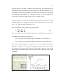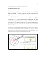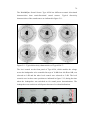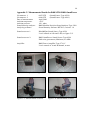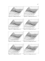
1
1
VAASAN AMMATTIKORKEAKOULU
UNIVERSITY OF APPLIED SCIENCES
DETERMINATION OF SOUND POWER
LEVELS USING SOUND INTENSITY
Michael Söderback
2009
2
PREFACE
This master's thesis is a part of my studies for a master's degree in construction
engineering, at Vaasan Ammattikorkeakoulu University of Applied Sciences. The
thesis served to provide myself a general introduction to acoustics and an in-depth
study of sound intensity for sound power determination. As an additional result of
the thesis, a computer software application was created for measurement data
analysis.
Michael Söderback
Vasa, June 10, 2009
3
VAASAN AMMATTIKORKEAKOULU
UNIVERSITY OF APPLIED SCIENCES
Rakentamisen koulutusohjelma, ylempi AMK-tutkinto
ABSTRACT
Author
Michael Söderback
Title
Determination of Sound Power Levels using Sound Intensity
Year
2009
Language
English
Pages
89 + 4 Appendices
Supervisor
Tapani Hahtokari
This thesis is a study in the determination of sound power levels of noise sources
by using the sound intensity method. The sound intensity method is suitable when
the measurements are carried out in field conditions where the acoustical
environment varies. The sound intensity method, for sound power applications, is
regarded as less sensitive to background noise than sound pressure measurements,
and therefore requires less special test facilities. This thesis also deals with
acoustics in general, basic concepts of sound and noise, are introduced and
studied.
The practical usage of the sound intensity method is introduced, by carrying out
measurements in a reverberant chamber on two sound sources, each with different
directivity pattern. By this arrangement in the given environment, the influence of
background noise on the determination of sound power levels of noise sources by
using the sound intensity method, could be studied and evaluated.
As a part of this thesis, a software application for measurement data analysis has
been developed. The application was created with the C++ language in a
programming workbench named MicroSoft Visual Studio 2008. In order for the
software to be able to read from the binary measurement data files, relevant data
properties were obtained by mapping these files by hex editing.
In the end, proposals for future investigation of the sound intensity method, and
for further development of computer software applications, for acoustic analysis,
have been given.
Keywords:
Sound pressure, sound intensity, sound power
4
VAASAN AMMATTIKORKEAKOULU
UNIVERSITY OF APPLIED SCIENCES
Rakentamisen koulutusohjelma, ylempi AMK-tutkinto
TIIVISTELMÄ
Tekijä
Michael Söderback
Opinnäytetyön nimi Äänitehotasojen määrittäminen ääniintensiteettimenetelmällä
Vuosi
2009
Kieli
Englantia
Sivumäärä
89 + 4 liitteet
Ohjaaja
Tapani Hahtokari
Opinnäytetyössä tutkitaan änitehotasojen määrittäminen ääniintensiteettimenetelmällä. Intensiteettimenetelmä sopii hyvin kenttämittauksille erilaisissa
akustisissa ympäristöissä. Äänitehotasojen määrittäminen ääniintensiteettimenetelmällä on yleisesti pidetty vähemmän herkkää taustamelulle kuin
äänipainemenetelmää ja näin ollen vähemmän akustiikkaan liittyviä vaatimuuksia
asetetaan mittausympäristölle. Opinnäytetyössä käsitellään myös akustiikkaa
yleisellä tasolla.
Intensiteettimenetelmän käytön tutkimista varten, suoritettiin kaiullisessa tilassa,
äänitehotasojen määrittäminen kahdelle erityppisille äänilähteelle. Taustamelun
vaikutus äänitehotasoihin ja mittaustarkkuuteen tutkittiin määrittämällä
äänilähteiden äänitehotasot kahdessa erilaisessa tilanteessa, ensin yksin ja
myöhemmin toisen äänilähteen vaikutuksen alaisena.
Työn yhtenä osana on C++-ohjelmointikielellä MicroSoft Visual Studio 2008ympäristöön toteutettu tietokonesovellus akustisten mittaustuloksien analysointia
varten. Mittaustulokset tiedostoissa olivat binäärisessä muodossa, joten niitä
kartoitettiin ensin hex editorilla.
Lopuksi annetaan ehdotuksia uusiin tutkimuksiin ja parannuksia tietokonesovellukselle.
Avainsanat:
Äänipaine, äänen intensiteetti, ääniteho
5
VASA YRKESHÖGSKOLA
Rakentamisen koulutusohjelma, ylempi AMK-tutkinto
ABSTRAKT
Författare
Michael Söderback
Lärdomsprovets namn Bestämning av ljudeffektnivåer med ljudintensitetsmetoden
År
2009
Språk
Engelska
Antal sidor
89 + 4 bilagor
Handledare
Tapani Hahtokari
Detta lärdomsprov är en studie av ljudintensitetsmetoden för bestämning av
ljudeffektnivåer. Metoden är användbar för fältmätningar i olika akustiska miljöer.
Ljudintensitetsmetoden för bestämning av ljudeffektnivåer anses allmänt som
mindre känslig för bakgrundsljud än ljudtrycksmetoden. I lärdomsprovet behandlas även grundläggande kunskaper och begrepp inom akustiken.
För att undersöka och utvärdera metodens användning i praktiken, utfördes
bestämning av ljudeffektnivåer för två olika ljudkällor i ett mätrum med lång
efterklangstid. De två ljudkällorna hade olika akustiska egenskaper med avsikt på
riktningen för den ljudenergi som utstrålas. Ljudeffektnivåerna bestämdes för
ljudkällorna både utan och med bakgrundsljud genererat av den andra ljudkällan.
Som en del av lärdomsprovet har ett datorprogram skapats för analys av akustiska
mätdata. Datorprogrammet har utvecklats med C++-programmeringsspråket i
MicroSoft Visual Studio 2008. Datorfiler med mätdata sparade i binär form,
kartlades med hex editering.
Till sist ges förslag om akustiska undersökningar och förbättringsförslag för
ytterligare utveckling av datorprogrammet.
Ämnesord:
Ljudtryck, ljudintensitet, ljudeffekt
6
TABLE OF CONTENTS
PREFACE
ABSTRACT
TIIVISTELMÄ
ABSTRAKT
1
INTRODUCTION…………………………………………………………....9
1.1 Technobothnia Researche Centre……………………………………….9
1.2 The Purpose …………………………………………………………….9
1.3 Restrictions…………………………………………………………….10
2
BASIC KNOWLEDGE……………………………………………………. 11
2.1 Basic Concept of Sound………………………………………………. 11
2.1.1 Sound and Noise……………………………………………….. 11
2.1.2 Basic Quantities of Sound……………………………………... 11
2.1.3 Sound Pressure………………………………………………… 12
2.1.4 The Decibel Scale……………………………………………… 13
2.1.5 Sound Sources…………………………………………………. 14
2.1.6 Sound Fields…………………………………………………… 16
2.2 Measuring Sound……………………………………………………... 19
2.2.1 Basic Sound Level Parameters………………………………… 19
2.2.2 Leq……………………………………………………………… 21
2.2.3 Measuring Sound in Practice…………………………………... 22
2.3 Basic Frequency Analysis of Sound…………………………………...22
2.3.1 Frequency and Wavelength……………………………………. 22
2.3.2 The Microphone……………………………………………….. 24
2.3.3 Frequency Analysis……………………………………………. 26
2.3.4 Perception of Sound…………………………………………….28
3
SOUND INTENSITY AND ITS APPLICATIONS……………………….. 31
3.1 Introduction to Sound Intensity………………………………………..31
3.2 Applications of Sound Intensity………………………………………. 32
3.2.1 Sound Power Determination……………………………………32
3.2.2 Noise Source Identification……………………………………. 33
3.2.3 Building Acoustics…………………………………………….. 33
3.3 Estimation of Sound Intensity………………………………………… 33
7
3.3.1 The Direct Method……………………………………………...33
3.3.2 Limitations……………………………………………………... 37
3.4 Validity of Sound Intensity Measurement Data……………………..... 42
3.4.1 Pressure-Intensity Index……………………………………….. 42
3.4.2 BT-product……………………………………………………...44
3.4.3 Pressure-Residual Intensity Index……………………………... 45
3.4.4 Dynamic Capability……………………………………………. 49
3.5 Calibration…………………………………………………………….. 50
3.5.1 Introduction……………………………………………………. 50
3.5.2 Sound Pressure Calibration……………………………………. 51
3.5.3 Verifying Sound Intensity and Particle Velocity……………….52
3.5.4 Measuring the Pressure-Residual Intensity Index…………….. 54
4
DETERMINATION OF SOUND POWER………………………………...57
4.1 Introduction to Sound Power…………………………………………..57
4.2 Comparison of different Sound Power Techniques…………………... 59
4.2.1 Introduction……………………………………………………. 59
4.2.2 Sound Pressure………………………………………………… 59
4.2.3 Sound Intensity………………………………………………… 60
4.3 Determination of Sound Power using Sound Intensity……………….. 61
4.3.1 Introduction and Definition……………………………………. 61
4.3.2 Influence of Background Noise………………………………... 64
4.4 Determination of Sound Power according to ISO 9614-2……………. 66
4.4.1 Introduction……………………………………………………. 66
4.4.2 Measurement Surface………………………………………….. 68
4.4.3 Partial Power Repeatability Check…………………………….. 68
4.4.4 Adequacy of the Measurement Equipment…………………… 69
4.4.5 Limit on Negative Partial Power………………………………. 70
4.4.6 Flowchart and Corrective Actions……………………………... 70
5
MEASUREMENTS………………………………………………………... 73
5.1 Test Setup Description………………………………………………... 73
5.2 Description for Measurement and Test Equipment…………………... 74
5.2.1 Sound Intensity Analyzer……………………………………… 74
5.2.2 Sound Sources and Accessories……………………………….. 76
5.3 Results and Analysis………………………………………………….. 80
8
5.3.1 Application for Measurement Data Analysis…………………… 80
5.3.2 Results…………………………………………………………... 82
6
CONCLUSIONS……………………………………………………………85
7
PROPOSALS FOR FUTURE WORK AND IMPROVEMENT…………...87
8
REFERENCES……………………………………………………………...88
Appendix A: Measurements Results for B&K OmniPower…………………….. 90
Appendix B: Measurements Results for B&K 4224…………………………….. 94
Appendix C: Measurements Results for B&K 4224 + B&K OmniPower ………98
Appendix D: Reverberation Time (T20) Measurement Results……………….. 105
9
1 INTRODUCTION
1.1 Technobothnia Research Centre
The Technobothnia research centre is a joint project, involving the ministry of
education, the city of Vaasa, the University of Vaasa, the Vaasa University of
Applied Sciences and the Novia University of Applied Sciences. All three
educational institutions are on the same campus as the Technobothnia research
centre. Technobothnia's mission statement is to provide a framework for highstandard research and education in the field of technology, serve as a channel of
cooperation between educational institutions, enterprises and other research
institutes and technology centres, offer education as well as research and product
development, measurement and testing services to the private and the public
sector. /12/. The acoustic section in the Technobothnia research centre's laboratory
of building physics provides acoustic measurements and analysis.
1.2 The Purpose
The purpose of this thesis work was to give myself a general introduction to
acoustics and an in-deep study of the determination of sound power levels using
sound intensity method. The determination of sound power levels were to be
carried out according to ISO 9614-2, using the Brüel&Kjær Modular Precision
Sound Analyzer Type 2260 Investigator. The purpose of this thesis work was also
to evaluate the fact that, sound intensity measurement used for sound power
determination, is regarded as not sensitive to background noise. The influence of
background noise, from a sound source with known acoustic characteristics, on
the determination of the sound source under test, was to be evaluated by carrying
out the test in a reverberant chamber. For the tests, two sound sources, each of
them with different acoustic directional characteristics, were to be positioned next
to each other. The sound power levels was then to be determined as the sound
source under test was running alone, as well as when the other sound source was
running parallel with the sound source under test. Parallel to the thesis work,
computer software for measurement data analysis was to be created.
10
1.3 Restrictions
The determination of sound power levels using sound intensity is carried out
according only to the standard ISO-9614-2 in a reverberant environment, on two
sound sources which have different directional characteristics. Measurements are
carried out as they run alone, as well as when they run together. Only the sound
intensity scanning method (ISO-9614-2) is used in the tests, and is therefore
studied more deeply in the theory part of this thesis.
This version of the computer software application, created for analysis of
measurement data stored in the analyzer by the sound intensity software BZ 7205,
is only displaying the data and it does not perform any calculations by itself.
11
2 BASIC KNOWLEDGE
2.1 Basic Concept of Sound
2.1.1 Sound and Noise
Sound is something that surrounds us each and every day. The most important
thing about sound is that we use it for communication. Communicating can mean
many things, it could be a truck driver just listen to the sound from the engine and
the engine will communicate to him when it is time to change gear. You can also
take pleasure in sound, for example listen to music or take a walk in the forest and
listen to some sound there.
But what is noise? Every time sound is unwanted, it is called noise. Noise can be
harmful and it may damage the hearing. It may also not be harmful, but maybe
just annoying. Typically when the neighbour is playing some music it is very
annoying, but not when you play music yourself. Noise does not have to be loud
to be annoying.
2.1.2 Basic Quantities of Sound
The three different quantities describing sound are sound pressure, sound intensity
and sound power, see table 2.1. Sound pressure is a scalar describing the pressure
fluctuation at a given position and is measured in Pascal (Pa). Sound pressure is
typically measured at the receiver's position for evaluation of the harmfulness and
the annoyance of a noise source.
Sound intensity is a vector quantity that describes the amount and the direction of
flow of acoustic energy at a given position. The unit for sound intensity is Watt
per square meter (W/m²). Measurement of sound intensity needs a special probe
consisting of two microphones and a sound intensity analyzer. Sound intensity
describes the path of sound and is used for noise source location and rating of
noise sources.
12
Sound power can only be calculated or determined either based upon sound
intensity measurement or based upon sound pressure measurement. The main use
of sound power is for noise rating of machines. For comparison of how noisy
various machines are the only way to compare them is to determine the sound
power. The unit for sound power is Watt (W) and is telling exactly how noisy the
machine is.
Table 2.1. Basic quantities of sound.
Quantity
Description Estimation
Sound pressure Receiver
Measured
[Pa]
Sound intensity Path
Measured
[W/m²]
Sound power
Source
Calculated
[W]
Usage
Evaluation of the harmfulness
and annoyance of noise sources
Location and rating of noise
sources
Noise rating of machines
2.1.3 Sound Pressure
Sound pressure can be generated for example with a tuning fork. The vibration of
the tuning forks two legs will activate the air molecule to vibrate and this
vibration are then transmitted through the air to the human hearing system. A
handclap produces a disturbance on the air molecules and this disturbance is then
travelling with the speed of sound to the receiver's ears. Waves can transport
energy from one place to another through a medium, but the medium itself is not
transported. A disturbance is passed along from point to point as the wave
propagates. A sound wave is a change in pressure and velocity. Throwing a stone
into the water will cause a disturbance in the water. This disturbance will then
travel away from the disturbance point in the shape of waves. The waves in the
water are getting smaller and smaller as they travel away from the disturbance
point. The handclap will produce a certain sound pressure level which decays to a
smaller value at the receiver's position further away.
The sound pressure is a small pressure variation on top of the atmospheric
pressure and is sometimes called the dynamic pressure. A typical sound pressure
is 1 Pa. Atmospheric pressure is typically 100 000 Pa or 1000 mbar and is
13
sometimes called the static pressure. The atmospheric pressure is measured with a
barometer and the sound pressure is measured with a microphone.
The highest and the lowest sound pressure that can be perceived by the human
hearing system are called threshold of pain and threshold of hearing. The ratio
between the threshold of pain and the threshold of hearing is seven orders of
magnitude.
Figure 2.1. Range of sound pressure and sound pressure level /5/.
2.1.4 The Decibel Scale
Sound pressure is measured in the unit Pa on an absolute scale which covers seven
orders of magnitude, see figure 2.1. But in acoustics it is preferable to use a
relative scale. With a relative scale it is possible to set the zero point at a certain
position and it has been chosen to be at the threshold of hearing. The threshold of
hearing is then used as a reference sound pressure p0 and has been determined to
be the sound pressure amplitude equal to 20 μPa, for a large population of young
persons with a good hearing system. The decibel scale is then defined by
comparing the sound pressure p to the reference sound pressure. Thus the sound
pressure level (SPL or Lp) is defined as: /10/
Lp = 10 log
p2
(dB)
p 02
(1)
There are several advantages with the decibel scale. One advantage is that the
human hearing system actually perceives sound or noise in a logarithmic fashion.
14
If, for example, the sound pressure is increased from 1 mPa to 10 mPa. That is an
absolute increase in sound pressure by 9 mPa. This will be perceived by the
human hearing system as the same change as if it first listen to a sound pressure of
1 Pa and then increased to 10 Pa. That is an absolute increase of 9 Pa, but the
human hearing system perceive this change to be the same.
Another reason for using the decibel scale is that this scale essentially is only
covering two others of magnitudes. This means that the numbers are easier to
handle. The ambient pressure that surrounds us is around 100 000 Pa and that
corresponds to 194 dB. It is not possible to produce a sound pressure level that is
exceeding the ambient pressure. This is of course far above the threshold of pain
where at the hearing system would be damaged.
2.1.5 Sound Sources
Sound sources are sometimes referred to as point sources, line sources and plane
sources, see figure 2.2. Every time the distance from a point source is doubled
under free field condition, the same amount of sound power or sound energy must
penetrate a surface which is four times larger. When the surface to penetrate is
four times larger, the sound pressure level is decreasing by 6 dB. This is why
sound pressure level measurements in free field condition highly depend upon the
distance from the sound source.
Figure 2.2. Three different types of sound sources /5/.
15
A line source can be a highway or a motorway. If the distance to a line source is
doubled, the sound pressure level is decreasing by 3 dB. The radiated noise from a
line source has the shape of a half cylinder. A doubled radius is increasing the
cylinders surface by a factor of two, thus decreasing the sound pressure level by 3
dB. A plane source can be a tube with a piston at the end of it or a stethoscope. If
there is no absorption in the tube, the sound pressure level will be the same at all
positions in tube, regardless of the length of the tube.
When combining sound pressure levels from multiple sound sources, their sound
pressure levels must be first converted back into sound pressure and then squared
before they are added together and then converted into decibels as shown earlier
in formula (1). This calculation is called power addition or RMS addition. There
exist also tables and charts for addition and subtraction of dB values. If there are
two uncorrelated sound sources and the sound pressure at a certain point due to
Source 1 is p1, and the sound pressure at that same point due to Source 2 is p2,
then the sound pressure level Lp due to both sources is: /10/
p12 + p 22
Lp = 10 log
p 02
(dB)
(2)
Where p0 is the reference sound pressure 20 μPa. In the case of two equal sources
p1 = p2, so that: /10/
p12
p12
p
Lp = 10 log 2 2 = 10 log 2 + 10 log 2 = 20 log 1 + 3 (dB)
p0
p0
p0
(3)
Thus, two sources which by themselves each cause, for example Lp=40 dB at a
certain location, will cause Lp=43 dB at that same location when sounded
together.
If two sound sources independently cause sound pressure levels of Lp1=50 dB and
Lp2=53 dB at a certain point, what is the sound pressure level at that point when
both sources contribute at the same time? /10/
L p1 = 10 log
p1 = p 0 10
p 2 = p 0 10
p12
p
→ L p1 = 20 log 1
2
p0
p0
Lp1
20
Lp 2
20
L p = 10 log
(dB)
(4)
= 6.32 ⋅ 10 − 3
(Pa)
(5)
= 8.93 ⋅ 10 − 3
(Pa)
(6)
p +p
= 54.8 (dB)
p 02
2
1
2
2
(7)
16
2.1.6 Sound Fields
Sound fields are typically near -, far -, free - and reverberant field. In the near field
close to the sound source there can be a large amount of pressure variations, from
one position to another position. Sound pressure level measurements in the near
field are therefore forbidden in many applications. In the near field the sound field
is very complex and complicated, which means that the sound pressure
distribution and the sound intensity distribution may look completely different. It
is a question of are they in phase or out of phase or what phase relationship there
is and also a question about wavelengths.
In the far field there is a more consistency in the sound field and sound pressure
levels will not vary too much when the measurement position is moved slightly.
The far field is also experienced if there is a free field situation. If the sound
pressure level decreases by 6 dB when the distance to a point sound source is
doubled, then there is a free field condition, see figure 2.3.
Figure 2.3. Sound fields /5/.
In the far field, far away from the sound source, there is a 1:1 relationship between
pressure, intensity and particle velocity, they look the same and they are all in
phase with each other. In the far field there is a free field situation.
17
If the measurement position is close to some boundaries like floors, walls and
ceilings, there might be reflections of sound as well as direct sound. In such a
sound field, a change in position further away or closer to the sound source may
not give a significant change in the sound pressure level, because a lot of the
sound pressure is caused by reflections. This is called a reverberant field or a
diffuse sound field.
A sound field with a diffuse character exists where the sound waves propagate
from all directions with the same probability and the same sound pressure level. In
factories where many sound sources exists simultaneously or in buildings with
hard walls, for example churches, sound fields with acoustic characteristics like a
diffuse field, may be found.
Anechoic rooms are set up to produce a free field situation and a controlled
acoustical environment. Anechoic rooms are used for many different purposes,
like for example, sound power determinations or measurement of the directivity
pattern of acoustic noise sources. In a free sound field the sound waves can
propagate freely without being disturbed by any object along their path. A sound
field at a distance 1-2 m away from the sound source can be regarded being a free
field, if no other sound source gives a significant contribution to the sound
pressure and there is no influence of reflecting surfaces.
Reverberation chambers are designed to produce a reverberant sound field by
making the walls and the boundaries as highly reflective as possible. The idea
with such a room is to have a controlled acoustical measurement. Reverberation
chambers are typically used for sound power determination of noise sources.
A sound field where the particle velocity is in phase with the sound pressure is
called an active sound field and constitutes the real part of a complex sound field.
In such a sound field all acoustic energy is transmitted and none of it is stored. An
example of this is a plane sound wave propagating in a free field. A sound field
where the particle velocity is 90° out of phase with the sound pressure is called a
reactive sound field and constitutes the imaginary part of a complex sound field.
18
An example is a standing wave, where the net flow of acoustic energy is zero, see
figure 2.4.
Figure 2.4. Standing wave /11/.
There exists also a test facility where there are two rooms next to each other and
they can both be reverberation chambers. Or one of them can be an anechoic
chamber, the other one can be a reverberation chamber. These are typically used
for measurement of transmission lost of panels.
Pressure fields are small enclosures, where the sound pressure is the same in terms
of magnitude and phase, everywhere in that sound field, and they are in size small
compared to the wavelength. Typically used in small couplers.
With the directivity index means that the sound pressure level will increase if the
sound source is positioned close to some boundaries, compared to the sound
pressure level of the same sound source in a free field situation, see figure 2.5.
The directivity index can be identified by positioning the sound source next to a
wall, where the index will be a factor of two corresponding to 3 dB.
In a junction of two planes there will be an increase of 6 dB and in a junction of
three planes there will be an increase of 9 dB. This means that the best place for a
loudspeaker is in a corner, because then it will produce the highest amount of
19
sound pressure levels. Because the same sound is then only radiating into much
smaller angle than if it was in a free field where it would be radiating in all
directions.
Figure 2.5. The Directivity Index /5/.
2.2 Measuring Sound
2.2.1 Basic Sound Level Parameters
Sound level meters are integrated measurement equipment with standardized time
weightings and also standardized measurement parameters. They consist of a
microphone, a pre-amplifier and detectors. The detectors for the most basic sound
level quantities are the RMS-detector and the Peak-detector. RMS stands for Root
Mean Square, see figure 2.6. This is the most important detector that there exists,
because this one will indicate the amount of energy or power there is in the sound
signal.
Figure 2.6. Basic Sound Level Parameters /5/.
20
Time constants or averaging times, used with a RMS-detector are typically fast,
slow or impulse. Fast is a time constant of 125 ms and slow is a time constant of 1
s. A fast detector will respond much faster to variations in the signal than the slow
detector. But after some time they would have reached the same level, the RMSlevel. A short time constant makes it easier to follow and track changes in the
signal and is typically used when analyzing rapidly changing signals, see fig. 2.7.
Figure 2.7. Time Weighting (RMS detector) /5/.
Slow time constant will smooth the data much better and is typically used for
averaging stationary signals. A longer averaging time minimizes the random error
in a signal. When the reverberation time is measured in a room, the time constant
in the analyzer must be shorter than the time constant of the room. Otherwise it is
the reverberation time of the analyzer that is measured, not the room.
Figure 2.8. Peak Hold (Peak Detector) /5/.
A Peak-detector must have some sort of hold facility for keeping the Peak level
until a new Peak value would arise that is higher than the previous one, see figure
2.8. The ratio between the Peak- and the RMS-value, called that the crest-factor, is
21
1.4 for a pure sinusoid signal. For a transient signal like a handclap, the crestfactor is higher.
2.2.2 Leq
The Leq is the sound level of a steady state noise source that is producing exactly
the same amount of sound energy, as a true fluctuating sound source over a certain
specific measurement time. Linear averaging means that all measurement data is
equally weighted and it is an arithmetic averaging of the noise signal, see figure
2.9. With the linear averaging there will be some starting random errors and with
a longer measurement time, the results will be smoother and give a better linear
average.
Figure 2.9. Equivalent Level Leq and measuring Leq, with linear averaging /5/.
Exponential averaging is a running averaging, which means it puts high emphasis
upon what happens right now and gradually forget about what happened in the
past, see figure 2.10. While with a linear averaging time all data is equally
weighted. With an exponential averaging, with fast time constant, there will be
continues random variations in the measurement data.
Figure 2.10. Leq for Transient Noise /5/.
22
2.2.3 Measuring Sound in Practice
Measuring sound in practice is a question of microphone position. The
measurement position should in general, be far enough away from reflecting
surfaces and where it does not disturb the sound field. The sound level meter
should be mounted on a tripod and the operator should be standing both behind
and aside the sound level meter. A field-check of the sound level meter with an
acoustical calibrator or a pistonphone should be done before and after each
measurement.
Measurement for standard procedures are defined in the ISO standard 1996
(International Standards Organization) Requirements for sound level meters are
defined in the IEC standards (International Electrotechnical Commission) where
they are divided into class 1 (Precision) and class 2 (General purpose) category.
For most practical purposes, type class 1 sound level meter is the most versatile.
2.3 Basic Frequency Analysis of Sound
2.3.1 Frequency and Wavelength
Different sound sources are producing sound in different frequency ranges.
Supertanker typically in very low frequencies and a violin in higher frequencies.
Frequency is measured in Hz indicating the number of oscillations per second for
a sound wave, see figure 2.11. For example the legs of a standardized tuning fork
are vibrating and producing sound with 440 oscillations per seconds.
Figure 2.11. Wavelength and Speed of Sound /5/.
23
The time period is the time it takes for the sound wave to oscillate from one
maximum to another maximum. The time period of a 1000 Hz oscillation is 1 ms.
The distance between two maxima of the sound wave is called one wavelength,
when looking at oscillations as a function of space. At low frequency the
wavelength is long and at high frequency the wavelength is short.
Angular frequency ω is used for simplifying mathematical expressions. The unit
of angular frequency is radians per second. This means that one cycle is exactly
360° or 2π. Thus the angular frequency is 2πf.
The wave number k is an alternative spatial descriptor:
2πf ω
=
(8)
λ
c
c
The wave number is used to non-dimensionalize size and distance in acoustics./5/
k=
2π
=
For characteristic dimension or distance d:
kd>>1, the item is acoustically large or the distance is acoustically far
kd<<1, the item is acoustically small or the distance is acoustically close
The characteristic dimension or distance kd is of course dependent upon the
frequency, see figure 2.12. The position might be acoustically in the near field at
low frequencies but acoustically in the far field at high frequencies. Likewise an
item might be acoustically small at low frequencies but acoustically large at high
frequencies.
Figure 2.12. Example of characteristic dimension d, free field correction /5/.
24
2.3.2 The Microphone
There exists many types of microphones and they can be divided into cheep
microphones, used for example in mobile telephones, studio microphones for
recording purposes and measuring microphones. The measuring microphone
consists of housing, an insulator, a diaphragm and a back-plate behind the
diaphragm, see figure 2.13. Measuring microphones are pressure sensing
condenser microphones and use a constant electrical charge for converting the
diaphragm displacement into an analog electrical signal. Measuring microphones
detect what the human ear detects, namely the pressure variations in the sound
field. The diaphragm and the back-plate are isolated from each other. There are a
number of holes in the back-plate and depending upon how many holes there are
the microphone is to be used in a free field or in a diffuse field. The number of
holes is determining how much damping the microphones has. A measuring
microphone has to have a number of special features, such as wide frequency
range, flat frequency response, wide dynamic range, low distortion, robust with
long term stability and simple design.
Figure 2.13. Cross-sectional view of a classic microphone type /2/.
25
A typical sensitivity of a microphone is 50 mV/Pa. So when 1 Pa is applied to the
microphone it corresponds to 96 dB. /5/
Measuring microphones are not symmetrical in all directions and therefore not
fully omni-directional. Also the mounting of the measuring microphones on a
sound level meter, will introduce a change in directional characteristics at higher
frequencies. When a microphone is inserted into a sound field, it will due to its
size, disturb the sound field. Typically there will be an increase of sound pressure
in front of the microphone, when the microphone is inserted into a free field and
there is a plane sound field arriving to the microphone diaphragm. Thus there will
be an overestimation of the sound pressure in the sound field, especially at higher
frequencies. At a frequency where the diameter of the microphone, is equal to the
wavelength of the sound field, overestimation might be as much as 10 dB /5/. By
drilling holes in the back-plate, the frequency characteristics can be changed at
higher frequencies.
Microphones have different sensitivities depending upon the angle of incidence
and depending upon of what type of sound field they are used in:
1. Free field microphone
2. Pressure field microphone
3. Diffuse field or random incidence microphone
Microphones with large diaphragm have high sensitivity and microphones with
small diaphragm have lower sensitivity. The smaller microphones are for
measuring high sound pressure levels and large microphones are for measuring
low sound pressure levels. On the other hand the larger the microphone is, the
more it disturbs the sound field. Large microphones are therefore used only up to
a limited frequency range; small microphones can be used up to very high
frequency ranges. /5/
26
2.3.3 Frequency Analysis
With frequency analysis of sound means the decomposing of the sound signal into
its various frequencies as indicated in figure 2.14.
Figure 2.14. Waveforms and frequencies /5/.
Typically the bandwidth of the filter is defined as being the upper frequency limit
minus the lower frequency limit, see figure 2.15.
Figure 2.15. Bandpass Filter and Bandwidth /5/.
In acoustics there is a long tradition for using what is called constant percentage
bandwidth (CPB) filters and they are best presented on a logarithmic frequency
axis. Constant percentage bandwidth means that each filter has a bandwidth which
is of a certain percentage of the centre frequency.
27
Figure 2.16. Third-octave Filter /5/.
The third-octave bandwidth filters are typically shown on a logarithmic display
because they appears very compressed together at low frequency, while they get
wider and wider at high frequencies, if shown on a linear display. Third-octave
filters are characterized by the upper frequency limit is the third root of 2
multiplied by the low frequency limit, and that turns out to be 1.26, which means
that the upper frequency limit is 26 % higher than the low frequency limit. See
figure 2.16 and table 2.2.
Table 2.2. Third-octave Passband /5/.
For third-octave frequency spectra, at 1 Hz the bandwidth is approximately ¼ of
an Hz. At 10 Hz the bandwidth is 2.6 Hz and at 10 kHz the bandwidth is 2600 Hz.
The bandwidth becomes broader and broader at higher frequencies, but the
relative bandwidth is the same, that does not change. It is a fix percentage. It is
28
standardized so that three third-octave bands are covering one octave band. This is
in contrast to vibration measurement where a Fast Fourier Transform (FFT)
analyzer is to prefer. The FFT analyzer uses what is called narrow band analysis
and a linear frequency axis. It has a constant bandwidth, which means that a FFT
frequency line has the same resolution at any centre frequency, see figure 2.17.
Figure 2.17. The Spectogram (FFT) /5/.
2.3.4 Perception of Sound
The audible range of the human hearing system is called audio sound and has
been defined to be typically in the frequency range from 20 Hz to 20 kHz, see
figure 2.18. Sound below 20 Hz is called infra sound and sound higher than 20
kHz is called ultra sound. But the auditory field is a little more complex and
complicated than just going from 20 Hz to 20 kHz. Because there is a threshold of
hearing also called threshold of quiet. This means that, there need to be a
relatively high sound pressure level, for example at 20 Hz before the human
hearing system can hear it, while for example at 4 kHz, the sound pressure level
does not have to be very high, in order for the human hearing system to detect it.
Figure 2.18. The Auditory Field /5/.
29
Threshold of pain are typically up around 130 dB in the full frequency range. But
the limit of damage risk is at lower sound pressure levels. Listening to a sound
pressure level of approximately 100 dB in the frequency range of 2-3 kHz, may
damage the hearing system. The frequency range for music is wider and has a
more dynamic range in sound pressure levels, than for speech.
More detailed information about the sensitivity of the human hearing system is
defined by the Equal Loudness Contours for Pure Tones, also called Phon-curves,
see figure 2.19. For example, listening to a 1 kHz pure tone with a sound pressure
level of 40 dB will generate a loudness impression of 40 Phon. But in order to get
a loudness impression of 40 Phon at 20 Hz, the sound pressure level, have to be
increased to 90 dB. The Phon-curve becomes more flat as sound pressure level
increases.
Figure 2.19. Equal Loudness Contours for Pure Tones /5/.
The 40-, 70- and 100 Phon-curves are the background for the acoustic weightings
called A-weighting, B-weighting and C-weighting. The A-weighting is an
approximation to the 40 Phon-curve by normalizing it to 0 dB at 1 kHz and then
inverting it, see figure 2.20. The idea with the different weighting curves was to
use the A-weighting for low sound pressure levels, B-weighting for medium level
sound pressure levels and C-weighting for high sound pressure levels.
30
Figure 2.20. The 40 dB Equal Loudness Contours inversed and compared to A-weight. /5/.
Over the years it has become a tradition to use the A-weighting and today most
acoustic measurements are made with A-weighting. In the most recent standards
there is only A- and C-weightings used. A-weighting typically under estimate the
sound pressure levels at low frequencies and also attenuates the results too much
in the frequency range of 3-4 kHz where the human hearing system is most
sensitive. The D-weighting is actually the most proper acoustic weighting to use,
but A-weighting is most commonly used in measurement standards, see figure
2.21. C-weighting is typically used for peek measurements where sound pressure
levels might be high as in an industrial environment.
Figure 2.21. A- , B- , C- and D-weighting curves /5/.
31
3 SOUND INTENSITY AND ITS APPLICATIONS
3.1 Introduction to Sound Intensity
Sound intensity is the rate of acoustic energy flow per unit area. Sound intensity is
a vector quantity and the unit is W/m2. Sound intensity is scaled into sound
intensity level in dB, when divided by the reference intensity 1 pW/m2 (1•10-12).
The real part of sound intensity, or the propagating part of the sound field, is
called active intensity. The imaginary part of sound intensity, or the nonpropagating part of the sound field, is called reactive intensity. /5/
Speed of sound c
Density of air r
Figure 3.1. Definition of Sound Intensity /5/.
The relationship between the three basic parameters of sound under free field
condition is indicated in figure 3.1, where an omni-directional sound source is
emitting a certain amount of power W. The intensity I on the surface at the
distance r is the radiated sound power W divided by the surface area 4πr². Or the
intensity I on the surface at the distance r is the sound pressure p squared and
divided by the impedance ρc of the air. The impedance of the air, in which the
sound wave propagates, is the speed of sound c multiplied by the density of air ρ.
32
The human hearing system is able to detect from which direction the sound is
arriving, because the sound is arriving at the two ears at a slightly different time.
Likewise an intensity probe consists of two microphones and thus enabling
detection of both direction and level of sound. An intensity probe has a cosine-like
directivity pattern of sensitivity, as indicated in figure 3.2.
Figure 3.2. Intensity Probe Directivity (Intensity) /5/.
3.2 Applications of Sound Intensity
3.2.1 Sound Power Determination
A major application of sound intensity is the sound power determination. It might
be a non-standardized measurement for indication of the sound power levels, or it
might be a measurement according to a standard. There exists several different
standards for sound power determination, and it is generally regarded to be more
time consuming when using standards, because there is a number of field
indicators that have to be monitored. Sound intensity measurement, is considered
to be not sensitive to background noise, when used for sound power
determination.
33
3.2.2 Noise Source Identification
A simple noise source location application is moving the probe forwards and
backwards around the sound source, and look for quick changes in the intensity
sign. This technique is suitable only when there is one major sound source
presence. A more advanced application is the noise mapping, which will generate
a complete noise map of the sound source, thus making it easy to pin point exactly
where the noise source is. Sound intensity enables source ranking by calculation
of how much sound energy or sound power is radiated from the various parts of a
sound source. One of the advantages of using sound intensity is that it gives
directional information, because sound intensity is a vector quantity. Sound
intensity also enables segmentation of a sound source, see figure 4.3.
3.2.3 Building Acoustics
Applications in building acoustics are, for example, sound reduction index,
leakage detection and sound absorption detection. For measurement of sound
reduction index there is typically a transmitter room and a receiver room. The
traditional way of measuring sound reduction index is with sound pressure level
measurements in two rooms.
When using sound intensity for sound reduction index, the sound pressure level is
measured in the transmission room, where the sound field is made as diffuse as
possible. In the receiving room the sound intensity is used to measure the energy
flow at various positions for mapping of the transmission. Sound intensity in the
transmitter room can be calculated from a formula, and is also called the one sided
intensity in a diffuse sound field. The sound reduction index is then the difference
between the calculated one sided intensity and the measured transmitted intensity.
3.3 Estimation of Sound Intensity
3.3.1 The Direct Method
A sound intensity probe consists of two microphones and based upon the
measurements of the sound field of two closely spaced positions in space the
34
sound intensity can be estimated. Sound intensity estimation is essentially a phase
estimation of the sound field.
Sound intensity I is defined as the time-averaged rate of energy flow per unit area.
A more mathematically definition is that the sound intensity vector equals the
time-averaged product of the instantaneous pressure and the corresponding
instantaneous particle velocity, at the same position: /5/
r
r
I = p (t ) ⋅ u (t )
(9)
r
Where p(t) is the instantaneous pressure, u (t ) is the particle velocity and the time-
averaging is indicated with a bar.
The particle velocity describes the actual motion of air particles as they oscillate
around their equilibrium or rest position. The higher sound pressure there is, the
higher the particle velocity becomes.
In acoustics an equivalent with the force in Newton's 2nd law is the pressure
gradient. There is no force on an air molecule if there is no pressure gradient.
With the pressure gradient means that there is a difference in pressure to the sides
of a particular point. If there was the same pressure in both points there will be no
pressure gradient. And if the pressure gradient is in a direction from low to high
pressure, then the force would be in the opposite direction, and therefore negative.
This explains the minus sign in formula (10). The sign due to the direction of the
pressure gradient is given by the definition of the intensity probe orientation.
A derivate of Newton's 2nd law, also called Euler's Relation is used to estimate the
average particle velocity u by measuring the pressure gradient p:
a=−
1
ρ
grad p
/5/
(10)
/11/
(11)
Where a is acceleration and ρ is the density of the air.
In one direction, r (see figure 3.4) there is:
∂u r
1 ∂p
=−
∂t
ρ ∂r
35
Then theoretically from Euler the particle velocity u is obtained by integrating the
pressure gradient with respect to time:
ur = −
1 ∂p
dt
ρ ∫ ∂r
/11/
(12)
In practice the pressure gradient is approximated as the pressure at one
microphone pB minus the pressure at the other microphone pA, divided by the
separation distance Δr between the two microphones. Thus giving the finite
difference approximation for the particle velocity u, in the direction r, at a point
midway between the two microphones as:
uˆ r = −
1
( p B − p A )dt
ρ ⋅ Δr ∫
/11/
(13)
This is a valid approximation as long as Δr<<λ /11/.
Figure 3.3. How Sound Intensity is Estimated /5/.
The average of the two instantaneous sound pressures in the two microphone
positions added together divided by 2, is an approximation to the sound pressure
midway between the two microphones. See figure 3.3.
36
Δr
pA
pB
direction r
Figure 3.4. Sound intensity in one direction r is estimated with two closely spaced
microphones.
The advantages with estimating the sound intensity with two microphones are that
measuring microphones are common transducers in acoustics, they can be used in
a wide variety of situations and they can be easily calibrated. Another advantage
is that the sound pressure and the particle velocity are calculated at the same time
and at the same location.
Figure 3.5. Estimation of Sound Intensity using Constant Percentage Bandwidth /5/.
When estimating sound intensity, using a constant percentage bandwidth analyzer
(see figure 3.5), the microphone signals from the pre-amplifiers are first converted
from analogue to digital signals. Then the output from the third-octave filters, are
after summation, squared and averaged, thus giving the mean pressure.
37
Sound intensity is calculated by taking the sum and the difference of the output
from the third-octave filters. This difference is then integrated with respect to
time. The difference is a quantity which is proportional to the particle velocity and
the sum is a quantity, which is proportional to the pressure midway between the
two microphones. Then the difference and the sum are multiplied and averaged.
Finally the scaling factor of 1/(2ρΔr) generates the result, where ρ is the density
of the air and Δr is the separation between the two microphones. This is called the
direct method, because both intensity and mean pressure can be calculated directly
according to the formulas.
3.3.2 Limitations
The frequency range of a sound intensity analyzer depends upon phase matching,
because essentially sound intensity estimation is really a phase measurement of
the sound signal, see figure 3.6. The limitations of a sound intensity analyzer are
that the phase matching must be good in order to calculate low frequencies
accurately. If microphones are too far apart, then high frequency resolution
degrades, and if they are too close together, the signal to noise ratio degrades.
Figure 3.6. Frequency Range Depends on Phase /5/.
38
The finite different approximation for the gradient of the instantaneous sound
pressure, will generate a larger error at high frequencies, see figure 3.7.
Figure 3.7. Theoretical Limitations at High Frequencies /5/.
It is obvious that if the separation between the two microphones were equal to half
a wavelength, then the two microphones would measure the same instantaneous
pressure but in opposite phase, thus generating a sum which is equal to zero.
Likewise, if the separation between the two microphones were exactly one
wavelength, then the two microphones would measure the same pressure and in
phase, thus generating a difference equal to zero.
At high frequency the separation between the two microphones must be smaller
than the wavelength. If the separation is approximately six (<60° of 360° = 6)
times smaller than the wavelength, or the phase change over the spacer is smaller
than 60°, then the sound intensity can be estimated within an accuracy of 1 dB.
Otherwise there will be what is called a finite difference approximation error.
Higher frequencies can be estimated by making the separation between the two
microphones smaller, but only up to a point where the signal to noise ratio is
becoming to poor. Signal to noise ratio depends also on the averaging time. High
frequency limit depends also on microphone dimensions.
39
For limitations at high frequencies there is a formula indicating the error in
estimating sound intensity level Lε as:
⎡ Iˆ ⎤
⎡ sin( kΔr ) ⎤
Lε = 10 log 10 ⎢ ⎥ = 10 log 10 ⎢
/5/
(14)
⎥ (dB)
⎣ kΔ r ⎦
⎣I ⎦
Where Iˆ is the estimated intensity, I is the corrected intensity and kΔr is the
characteristic dimension for the spacer.
This means that the estimation is correct up to a certain upper frequency limit and
then there will be an under estimation, see figure 3.8. There might even be an
incorrect direction of the estimated intensity.
Figure 3.8. Limitations at High Frequencies /5/.
In order to estimate the sound field with 1dB accuracy, at for example 500 Hz
where the phase to be detected is 6.28°, the system must have a phase match
which is at least better than 1.26° (approximately five times better).
At low frequency it is also a phase-issue, see figure 3.9. Here it turns out that the
phase change over the spacer due to the sound field must be at least five times
bigger than the phase mismatch between the two microphones in order for the
sound intensity to be estimated within an accuracy of 1 dB.
The low frequency limitation of an analyzer is determined by the phase matching
between the entire measurements chains of the system. The low frequency limit
for sound intensity estimation depends on the PI index of the sound field and the
Dynamic Capability (phase match and spacer) of the analyzer. The frequency
40
limit can be lowered by decreasing the PI index by measuring closer to the sound
source or by adding absorption material into the room. Dynamic Capability can be
improved by increasing the size of the spacer and by improving phase matching.
Figure 3.9. Limitations at Low Frequencies /5/.
For example, if a sine signal at 100 Hz, which has a wavelength of 3.6 m, is
estimated with an intensity probe, where the microphone separation is 1 cm, then
the estimation should be a 1° difference of the sound field (360cm ↔ 360°).
Because there is 1° degree difference between the microphones if they are 1 cm
apart. Then of course the matching of the two channels must be better than 1°, and
it must be five times better for not having a significant error.
If the microphones were matched to 1° and the estimated sound field signal is 1°,
then the result of the estimation would be 2° or 0° depending upon if the phase
difference of this instrument is subtracting or adding to the phase difference of the
sound field. If the estimation is 2° rather than 1°, then it is an over estimation of 3
dB and if the estimation is 0° rather than 1°, then it will be an under estimation
which is infinitely high.
A change of the spacer size shifts the frequency range. For example a 12mm
spacers upper frequency limit is 5 kHz and with a phase match of the system of
0.1°, the low frequency limit is 40 Hz. Likewise a phase match of the system of
0.05°, which is two times better, then the frequency range is two times lower
41
down to 20 Hz. A change in spacer from 12mm to 6mm would typically just shift
the entire frequency range a factor of two up. Or a change in spacer from 12mm to
50mm would shift the range a factor of four lower in frequency. See figure 3.10.
Figure 3.10. Change of Spacer Shifts Frequency Range /5/.
Microphones used for sound intensity estimation, differs from microphones used
for ordinary sound level meters. The phase match of these microphones can be
improved by adding phase correctors. There is a ventilation hole for equalizing
changes in the ambient pressure, which are large pressure variations compared to
sound pressure variations. A leak of sound pressure outside the microphone to the
inside of the microphone, is creating a phase change at low frequencies and the
phase matching between microphones is a question of being able to control the
tolerances in making these equalization holes. By adding more equalization holes,
further attenuation is made of the sound field that is detected through the
ventilation holes. Thus making these microphones less sensitive to low pressure
through the ventilation hole, compared to a normal microphone. This is improving
the low frequency phase matching, and it also improves the low frequency
performance for sound intensity estimations. It is of course possible to correct for
phase mismatch by measuring the phase mismatch of the system and then correct
subsequent estimations automatically. This will improve the dynamic range of
such a sound intensity system.
42
3.4 Validity of Sound Intensity Measurement Data
3.4.1 Pressure-Intensity Index
The quality of sound intensity measurement is typically checked by comparing the
pressure-intensity index (PI index) to the Pressure-Residual Intensity index (PRI
index). The PI index is a property of the sound field and the PRI index is a
property of the measurement system. The PI index is expressed as:
F pI = L p − LI
(dB)
/5/
(15)
The PI index FpI, is the level difference between sound pressure and sound
intensity, indicating if the measurement was made in free field or reverberant
field. Under free field condition, sound pressure level and sound intensity level is
due to choice of references, exactly the same and is the easiest sound field to
handle, see figure 3.11.
In other types of sound fields there might be more sound sources or there might be
a reverberant sound field, where there is an increasing level difference between
sound pressure level and sound intensity level, thus increasing the PI index. These
sound fields are more complex and complicated to work with.
Figure 3.11. The Relationsship Between Pressure and Intensity in a Free Field /5/.
43
Under free field condition when sound is propagating along the probe axis in one
direction only, sound intensity level and sound pressure level is the same. In three
different other situations the sound intensity level is smaller than the sound
pressure level:
1. Sound propagates at an angle towards the probe axis
2. There are two or more sources in a free field
3. The sound field is diffuse, meaning there is reflections
When the orientation of the probe is pointing in the direction of the sound
propagation, the phase change Δϕ across the spacer is:
Δϕ =
Δr ⋅ 360 °
/5/
(16)
(° )
λ
where Δr is the spacing between the microphones and λ is the wavelength. But if
the orientation of the probe is not in the direction of sound propagation, see figure
3.12, then the detected phase change Δϕ across the spacer is modified as:
Δϕ =
Δr ⋅ cos θ ⋅ 360 °
(°)
/5/
(17)
λ
where θ is the angle of propagation. As a result the detected intensity will be
lower and the effective spacer distance reduced as:
Δreff = Δr ⋅ cos θ
(mm)
/5/
(18)
Figure 3.12. Sound propagating towards the probe at an angle or along probe axis /5/.
44
The FpI is of course frequency dependant, some frequencies have a more free field
character than other frequencies. In a free field where there is a purely active
sound field, the FpI is equal to zero dB and the sound pressure and the
corresponding particle velocity is in phase with each other, when pointing the
intensity probe towards the sound source.
In a purely diffuse sound field, the FpI is very large and the pressure and the
particle velocity are uncorrelated. When pressure and particle velocity at the same
point are uncorrelated then the intensity is equal to zero.
An extreme type of sound field where intensity is behaving quite different from
pressure, than in any other sound field, is the standing wave. A standing wave is
characterized by that the pressure and the particle velocity is 90° out of phase with
each other and their product becomes zero. In a standing wave the intensity level
is equal to zero, because it is the mean level between the maximum sound
pressure and the minimum sound pressure.
3.4.2 BT-product
The FpI is used for evaluating both random and systematic BIAS errors. For
random error on a sound pressure level measurement data, there is a confidence
level or a standard deviation in terms of accuracy of the correct level of 68%
given in the chart in figure 3.13, as a BT product and extended as a function of
FpI. For BT product, B is the bandwidth of the filter and T is the measurement
time.
If, for example, the BT product is equal to 600, for sound pressure level
measurement, then the accuracy in terms of standard deviation is ± 0.2 of a dB. In
order to get the same statistical accuracy in the sound intensity measurement
where FpI is equal to 10, then the BT product most be equal to 104. If the FpI is
equal to zero, the same statistical accuracy is obtained as for sound pressure
measurement.
45
Figure 3.13. Random Error (68% Confidence Level) /5/.
In order to obtain more accurate results, a longer averaging time should be used,
thus reducing the random error. Generally at lower frequency where the
bandwidth is smaller and the random error is larger, a longer averaging time is
needed in order to get the same BT-product, as for a higher frequency, where the
bandwidth is larger. For a third-octave sound intensity analyzer, the required
averaging time is therefore determined by the lowest frequency of interest.
An example of where the averaging time makes a difference is when measuring
the PRI index. Here the microphone probe is mounted into a coupler where a
sound field with high FpI is simulated. Then the required averaging time in order
to measure inside the coupler is much longer than for a measurement under free
field condition. The FpI can be used to establish how much averaging time is
needed, because the higher FpI there is the longer averaging time is needed.
3.4.3 Pressure-Residual Intensity Index
Phase match and accuracy of intensity probe and analyzer together is indicated
with the pressure-residual intensity index (PRI index). A higher PRI index means
that the instrument is better phase matched. The PRI indexes is measured on the
intensity analyzer by mounting the intensity probe into a sound intensity calibrator
and expose both microphones to the same pink noise sound. This method
46
corresponds to either having the intensity probe in a free field with a 90° angle of
incidence or having it in a diffuse field situation.
When both microphones are exposed to identical pink noise sound, the estimated
intensity is expected to be equal to zero, see figure 3.14. But real measurement
probe and analyzers have phase mismatch and therefore some intensity is
detected. This detected intensity is called the residual intensity of the analyzer,
and is a false intensity produced by the phase difference between measurement
channels. If the entire measurement chain was perfectly phase match, the residual
intensity would be zero W/m² or -∞ dB. Since phase is not an integral part of a
pressure measurement, the pressure remains the same at both microphones. The
level difference between the indicated sound pressure level Lp and the indicated
residual intensity level LI in one octave or one-third octave bands, is then called
the Pressure-Residual Intensity index and is expressed as:
δ pI = L p − L I
0
(dB)
/5/
(19)
Figure 3.14. Pressure Residual Intensity Index /5/.
Sound intensity measurement instruments are classified in the IEC 1043 standard
according to the measurement accuracy achieved. The accuracy specifications are
based on frequency response, filtering, PRI index and environmental sensitivities.
There are two grades of accuracy, designated as class 1 and class 2. The class 1
where the processor and calculating accuracy is better than ±0.2 dB and the class
2 where the processor and calculating accuracy is better than ±0.3 dB. The same
requirements apply to both classes; the differences are only in the tolerances and
in the pressure-residual indices. A class 2 requirements are stringent than those for
47
class 1. There is an additional class, designated as 2X, which has the same
requirements and processor accuracy as class 2, except that real time performance
is not required. /8/. The minimum PRI index requirements for class1 instruments
with 12 mm nominal microphone separation, is indicated in figure 3.15.
Figure 3.15. PRI index (δpI0) and the IEC 1043 standard /5/.
The error due to phase mismatch can be both positive and negative. If, for
example, the sound fields phase change between the microphones is 1° and
instrument is only matched with 1° accuracy, then the estimation of phase change
would be either 2° or 0°. If the PRI index of the instrument and the P-I index of
the sound field is exactly the same, then there is an error due to phase mismatch
which can be +3 dB or -∞ dB, see figure 3.16. This is because the error introduced
due to phase mismatch is either adding or subtracting to the estimation.
If the intensity of the sound field is a positive value and the residual intensity of
the instrument is a negative value, then they subtract. But if the intensity of the
sound field is a positive value and the residual intensity of the instrument also is a
positive value, then they add together. This is in difference to sound pressure
measurement where background noise only adds to the measurement results and
thus giving a too high estimate.
48
Figure 3.16. Error due to Phase Mismatch of the Instrument /5/.
An example of PI index, PRI index, Ld(10dB), Ld(7dB) and IEC-minimum values in
the same graph, produced by the software created in this thesis work, is indicated
in figure 3.17.
Figure 3.17. Example of P- index, δpI0, Ld(10), Ld(7), IEC-minimum values.
49
3.4.4 Dynamic Capability
The PRI index of the instrument minus a safety margin must be higher than the PI
index of the sound field. For the estimation of the sound intensity level to be
within an accuracy of ± 0.5 dB, there must be a safety margin or a difference of 10
dB or higher, between the PRI index of the instrument and the PI index of the
sound field. Likewise, to have an accuracy of ± 1 dB, the safety margin must be
not less than 7 dB. This safety margin is called K factor and described as BIAS
error factor, in the standard ISO 9614.
The dynamic capability index is the difference between sound pressure level and
sound intensity level, within which measurements to precision, engineering and
survey grades of ISO 9614 may be made. ISO 9614 gives requirements for the K
factor according to the grade of measurement accuracy required. This K factor is
subtracted from the PRI index, to give the dynamic capability index of the
analyzer, fig. 3.18. The dynamic capability indicates the dynamic range for
intensity measurement, and the dynamic range of the analyzer must be bigger than
the dynamic range of the sound field. Dynamic capability index Ld is expressed as:
Ld = δ pI 0 − K
(dB)
/5/
(20)
Once the dynamic capability is determined, this value is compared to the
measured PI index of the sound field as:
-if the PI index < dynamic capability, desired accuracy is achieved
-if the PI index ≥ dynamic capability, measurement does not meet desired accuracy
7 dB
10 dB
Figure 3.18. Dynamic Capability Example /5/.
50
3.5 Calibration
3.5.1 Introduction
Calibration of a sound intensity analyzer includes sound pressure calibration of
the individual microphone channels, verifying the sound intensity and particle
velocity levels and measurement of the pressure-residual intensity index. This
requires an intensity coupler, a pistonphone, a broadband noise source and a
correction barometer, see figure 3.19. The correction barometer determines the
correction terms to the calibration levels of sound pressure and particle velocity,
due to changes in atmospheric pressure. The sound intensity calibration level is
not influenced by changes in atmospheric pressure. A calibration chart is also
needed that states the levels that should be detected during calibration.
Figure 3.19. B&K Sound Intensity Calibrator Type 3541 Components in Their Case.
An intensity coupler consists of housing and two chambers connected by a
coupling element. There is also a removable dummy microphone for closing
unused chamber openings, as indicated in figure 3.20.
Figure 3.20. Simplified Cross Section of a Sound Intensity Coupler /4/.
51
3.5.2 Sound Pressure Calibration
The sensitivity of each microphone is supplied by the manufacturer and has to be
keyed in into the analyzer setup. The gain adjustment factor for each microphone
channel is obtained by a sound pressure calibration. The coupler and the
pistonphone are used for sound pressure level calibration of each measurement
channel. The pistonphone is mounted on the coupler, and the microphones are
positioned in the upper chamber of the coupler, see figure 3.21. The pistonphone
produces the same sound pressure, with respect to both amplitude and phase, at
each microphone. Each microphone channel is then gain calibrated against this
known sound pressure level. The pistonphone produces a pure tone, typically at
250 Hz. In the calibration setup of a sound intensity analyzer, the user typically
has to key in the calibration level, the ambient temperature, the ambient pressure
and also the correction terms from a correction barometer. The pressure from the
pistonphone is depending upon the ambient pressure. For the calibration level, the
sound pressure level given on the calibration chart of the calibrator is used.
Figure 3.21. Sound pressure calibration using a pistonphone and an intensity coupler.
The error in estimated intensity Lε,gain, due to error in the gain adjustment factor is:
⎡ Iˆ ⎤ C + C B
Lε , gain = 10 log 10 ⎢ r ⎥ = A
2
⎣⎢ I r ⎦⎥
(dB)
/5/
(21)
Where CA and CB is the error in gain adjustment factors (dB). If only channel B is
calibrated and channel A has an error in sound pressure level of, for example 1
dB. Then the error introduced on sound intensity measurement, due to the error in
the gain adjustment factor for channel A, is 0.5 dB. Generally this is not a critical
error, the phase match of the analyzer is much more critical.
52
3.5.3 Verifying Sound Intensity and Particle Velocity
Calibration of sound intensity determined from a two microphone pressure
measurement, requires knowledge of sensitivity and gain adjustment, phase match
and effective acoustical separation of sound pressure transducers used with the
analyzer. Knowledge is also required about the density of the fluid medium,
which is influenced by the temperature, ambient pressure and composition of the
medium. The estimated sound intensity is then obtained according to the direct
method as:
Iˆ =
1
( p A + p B ) ∫ ( p A − p B )dt
2 ρΔ r
(dB)
/5/
(22)
Where PA is pressure in channel A and PB is pressure in channel B, Δr is the
effective acoustical separation of the two microphones, ρ is the density of the
medium. The density varies with temperature, ambient pressure and composition
of the medium (normally air).
The intensity can be estimated by assuming a reference density ρref for the
acoustic medium, then compensation is made for the true intensity I. If density ρref
is assumed to estimate intensity Iref, and the true density isρ, then the true intensity
I is obtained from:
⎡ ρ ⎤
L I = L I ref − 10 log 10 ⎢
⎥ (dB)
/5/
(23)
⎢⎣ ρ ref ⎥⎦
Intensity can also be estimated by assuming a reference ambient pressure p0ref and
a reference ambient temperature Tref for the acoustic medium, then compensation
is made for the true intensity I. If p0ref and Tref is assumed to estimate intensity Iref,
and if the true ambient pressure is p0 and the true ambient temperature is T, then
the true intensity I, is obtained from:
⎡ p ⎤
⎡ T ⎤
L I = L I ref − 10 log 10 ⎢ 0 ⎥ + 10 log 10 ⎢
⎥ (dB)
/5/
(24)
⎢⎣ p 0 ref ⎥⎦
⎢⎣ Tref ⎥⎦
It turns out that the density is proportional to the ambient pressure and inverse
proportional to the temperature.
Acoustical separation between the microphones is the distance between the
acoustic centers of the microphones and is depending upon frequency. Acoustical
53
separation is measured in anechoic chambers, as a function of frequency. At some
frequencies, the acoustic center is in front of the diaphragm and at some other
frequencies, it is behind the diaphragm. The error due to the effective acoustical
separation Lε, separation of the microphones is given as:
⎡ Δr ⎤
Lε , separation = 10 log 10 ⎢ ⎥
/5/
(25)
⎣ Δr ' ⎦
Where Δr is the actual spacing and Δr’ is the nominal spacing. The acoustical
separation between the microphones is normally supplied by the manufacturer.
The analyzer must also be calibrated with respect to the acoustical separation.
Figure 3.22. Setup for sound intensity and particle velocity calibration.
The analyzers sensitivity to sound intensity and particle velocity can be verified
by using both chambers of the coupler. Each microphone of the intensity probe is
positioned in different chamber and the pistonphone is mounted on the top of the
coupler, as indicated in figure 3.22. With this arrangement the pistonphone
generates a phase difference between the sounds pressures in the different
chambers, but the sound pressure amplitude in the chambers is the same, thus
simulating a plane sound wave propagating in a free field along the axis of the
probe. The analyzers sensitivity to sound intensity and particle velocity is then
verified against the known corresponding levels, indicated in the supplied
calibration chart.
The acoustical medium between the two chambers puts up a time delay, which
corresponds to a 50 mm spacer. By setting up the analyzer for a microphone
spacing of 50 mm, it is possible to verify, that the sound intensity and the particle
velocity is calculated correctly in the analyzer.
54
In figure 3.23, a simplified block diagram is indicating how sound intensity is
estimated. The particle velocity signal is given by:
ur = ∫
( p A − pB )
dt
ρ Δr
/4/
(26)
Figure 3.23. Block Diagram of Sound intensity Estimation /4/.
3.5.4 Measuring The Pressure-Residual Intensity Index
The purpose of measuring the pressure-residual intensity index is to minimize the
phase mismatch of the sound intensity analyzer. The phase mismatch is largest at
low frequencies, and if the phase matching between the two measurement
channels is poor, the pressure-residual intensity index will be low and the sound
intensity at these frequencies will not be estimated accurately.
The upper chamber of the intensity coupler, is used with a broad-band sound
source for measuring the pressure-residual intensity index of the analyzer, or in
other words; to determine the phase mismatch between the two measurement
channels, see figure 3.24. The broad-band sound source produces pink noise,
creating a diffuse sound field with a high PI index, in the chamber. Due to the
high PI index, an averaging time not less than two minutes, is required.
Figure 3.24. Verifying a pressure-residual intensity index.
55
When a sound wave propagates at an 90° angle towards the probe axis,
differences in phase responses of the microphones cause a phase difference
between the microphone signals, and there appears to be an acoustic flow of
energy along the probe axis. Because each microphones is exposed to equal sound
pressure, any intensity detected is residual intensity. The residual intensity
spectrum is not tied to variations in measured sound pressure level. The pressureresidual intensity index is a constant, and is obtained by subtracting the detected
residual intensity spectrum from the measured mean sound pressure spectrum, see
figure 3.26. An example of pressure-residual intensity index spectra after phase
calibration, shown with minimum values required by IEC 1043, as seen on screen
of a B&K 2260 Investigator sound intensity analyzer, is indicated in figure 3.25.
The error in gain adjustment factor Lε,gain, due to phase mismatch between the two
measurement channels of a sound intensity analyzer is given as:
⎡ sin φ m
⎤
Lε , gain = 10 log 10 ⎢
⎥ (dB)
⎣ sin(φ m − φ ε ) ⎦
/5/
(27)
Where φm is the measured phase and φε is the phase mismatch.
The largest phase mismatch of a sound intensity analyzer is between the
microphones, followed by the pre-amplifiers and the input channels of the system.
Figure 3.25. Pressure-residual intensity index shown with IEC-minimum values /6/.
56
Figure 3.26. An example of where sound intensity and sound pressure levels are
measured in the coupler, while verifying the pressure-residual intensity index. By
subtracting the sound intensity level spectra from the sound pressure level (SPL)
spectra, the pressure-residual intensity index spectrum is obtained. /4/
57
4 DETERMINATION OF SOUND POWER
4.1 Introduction to Sound Power
Sound power is the rate per unit time at which airborne sound energy is radiated
by a source, and its unit is Watt [W]. Sound power is a quantity which can not be
measured; it can only be calculated or determined based upon either sound
pressure measurement or sound intensity measurement. The sound power levels
Lw is defined as:
⎛W ⎞
⎟⎟ (dB)
L w = 10 log 10 ⎜⎜
W
⎝ 0⎠
where the reference sound power W0 is 1 pW
/5/
(28)
The three basic parameters of sound compared:
1. Sound Pressure is dependent on the acoustic environment and is a product of
the sound source(s) and the acoustic environment
2. Sound Intensity is dependent on the acoustic impedance of the medium and is a
descriptor of the radiation of sound power through the medium
3. Sound Power is independent of the acoustic environment and is therefore a
good parameter for making comparisons of sound sources
Figure 4.1. Sound Pressure vs. Sound Power /5/.
In figure 4.1, the analogy of sound pressure vs. sound power is described with a
heater in a room. A heater will emit the same amount of heat from any position in
58
any room, but the temperature in the room is highly depending upon in what kind
of environment the heater is. For example, depending on if it is winter time or
summer time, the temperature in the room due to the heater, would be different,
even though the heater is producing the same amount of heat all the time. Or in
other words; the power of the heater is known, but its influence on the temperature
of the air, at the position of the thermometer is unknown, and depending on the
environment.
It is the same thing about a sound source; a stationary sound source is always
producing the same amount of sound. But the sound perceived in the room, is
depending upon the acoustic properties of the room, it might be an anechoic or a
reverberation chamber or any other room, and it is also depending upon the
distance to the sound source. But the sound source itself is always emitting the
same amount of sound. It is just the pressure in the room that would be different,
due to the acoustic properties of the room. So the sound pressure is highly
depending on, not only the sound source but also what kind of environment the
sound source is placed in. This is why Sound Power is the basic quantity for
characterizing a sound source.
If there is a knowledge of the sound power levels Lw, of a sound source and of the
properties of the acoustic environment, the sound pressure level Lp, due to that
sound source at a given distance r, in that environment, can be predicted by
adding some correction terms to the sound power levels as:
L p = L w + 10 log 10 ⋅ Q − 10 log 10 ⋅ r 2 − 11 (dB)
/5/
(29)
Where Q is the directivity factor. In a free field situation, the directivity factor is
equal to one or 0 dB. But if the sound source is close to a wall, the directivity
factor is two or 3 dB. If the sound source is placed between wall and floor, the
directivity factor is equal to four or 6dB, and if it is placed in a corner then the
factor is eight corresponding to 9 dB. The correction term of 11 dB corresponds to
4π. This means that with knowledge of the sound power of a sound source, it is
possible to predict what the sound pressure is at any position in space.
59
Sound power is used to determine that a sound source complies with noise
specifications, which means that in order for manufacturers to be able to sell noisy
machinery and equipment, they have to declare the maximum sound power level
emitted by their product. For engineers trying to develop more quiet machinery
and equipment, sound power is the best and only quantity that really describes the
noise of a sound source and enables noise emission comparison.
4.2 Comparison of different Sound Power Techniques
4.2.1 Introduction
The sound pressure and the sound intensity based methods for determination of
sound power levels are standardized in the ISO committee. The idea with
standards in acoustics is to make sure that everybody use the same method, thus
simplifying comparison of results, but the standards does not guarantee that
everything is done correctly, it is just to ensure that everybody do the
measurement in the same way. Standards for Sound Power determination comes
in three grades of accuracy; survey grade (least accurate), engineering grade
(medium accuracy) and precision grade (most accurate).
The different techniques of sound power determination will yield the same result,
because the sound power is a property of the sound source which is independent
of where the sound source is placed. Common for all techniques is the assumption
that the sound source is stationary, and that octave and third-octave sound power
levels are calculate from the measurement, and then the overall sound power level
is just synthesized from octave or third-octave data.
4.2.2 Sound Pressure
Sound power determination by sound pressure measurements is based upon the
ISO 3740 series of standards and they typically require that there is a known
acoustic environment. The sound pressure method can be roughly divided in to
free fields methods in anechoic rooms, and diffuse field methods in reverberation
rooms.
60
With the free field method, typically a hemisphere, a parallelepiped or a shoe box
is used to define the surface around the sound source, and then the measurement
points are at the exes on the corners of these surfaces. While in a reverberation
chamber, there is typically a reference sound source (RSS) and the device under
test (DUT). The determination of sound power levels is then by simply making a
comparison between the sound pressure measurements of RSS and of DUT.
Typically a rotating boom is used to get an average of the sound pressure in the
entire room. Because no room is perfect, if it was perfect, it was good enough just
to make measurement at one point. But because of imperfections, it has to be
measured in a number of points and averaged, or measured by using a rotating
boom.
The advantages with the sound pressure method for determination of sound power
levels, is that it gives reliable result, relatively simple to follow and gives a wide
frequency and dynamic range. But the disadvantage is that it requires a qualified
acoustic test facility. The pressure methods are used for production audits and
testing, high volume testing, determination of low-level sound powers and where
the user already has an acoustic test facility. Pressure method is best suited for
non-qualified personnel.
In standardized sound power determination using sound pressure, the standard
require that measurements are carried out in the far field of the sound source, and
the distance between the measurement points and the sound source, is depending
upon the size of the object under test.
4.2.3 Sound Intensity
The sound intensity methods for sound power determination can roughly be
divided in to point or scanning measurement and they are standardized in three
versions. Version 1 (ISO 9614-1) is discrete point measurement with precision,
engineering or survey grade. Version 2 (ISO 9614-2) is measurement by scanning
with engineering or survey grade. Version 3 (ISO 9614-3) is measurement by
scanning with precision, engineering or survey grade.
61
These methods can be used in-situ in almost any acoustic environment, which
means that a special acoustic test facility is not required. They also includes
location, ranking and segmentation of noise sources, which means that it is
possible to calculate how much sound power is emitted from various parts of the
device under test. Sound intensity gives directional information and isolates the
object under investigation. There is no restriction on the shape of the control
surface. Sound intensity method has less demand on the background noise, and
steady background noise is excluded. Sound intensity measurements, can be
carried out in both the near-field and the far-field of the sound source. Absorption
material inside the control surface might introduce an under estimation of the
sound power.
The sound intensity method is best suited for research and development and
engineering testing, because it sets higher demands to the operator's skills. The
method is used for engineering measurements in development of new product, insitu and survey measurements and for measurements where it is not convenient or
possible to put the device under test in an acoustic test facility.
Sound intensity rather than sound pressure, is used because it is a vector quantity
that measures the energy flow, thus giving directionality information. With
directionality information, it is possible to determine if a surface area is radiating
sound or absorbing sound. This information can not be found with a sound
pressure measurement. Sound pressure measurement, in most cases, must be
carried out in the far field. Sound intensity measurement, can be used both in the
near field and in far field without having any near field artifacts.
4.3 Determination of Sound Power using Sound Intensity
4.3.1 Introduction and Definition
When using sound intensity method for sound power determination a
measurement surface is defined around the sound source under test. Then either
by point or scanning measurements on the surface, the results are averaged
together, see figure 4.2. The scanning method is easier to use than the point
62
method. With the scanning method, the intensity probe is moved forwards and
backwards over the surface, as if it was being painted. The accuracy of the
sweeping introduces a random error and the accuracy of the surface area
introduces a BIAS error, on the measurement results.
ISO 9614 Part 2&3 (sweep)
ISO 9614 Part 1 (point)
Figure 4.2. Scanning and Point Measurement Methods /5/.
The definition based upon intensity, is that sound power is the surface integral of
the sound intensity over a controlled surface, or measurement surface which is
completely inclosing the sound source of interest, see figure 4.3.
Figure 4.3. Definition of Sound Power from Sound Intensity /5/.
The sound power level Lw (W) from sound intensity measurement on a surface
area S is calculated as:
⎛ S
L w = L I + 10 log 10 ⎜⎜
⎝ S0
⎞
⎟⎟ (dB)
⎠
/5/
(30)
Where LI is the estimated intensity level (dB), S is the surface area (m²) and S0 the
reference surface area of 1 m².
63
Any measurement surface can be used, for example hemisphere or a box surface
or a conformal surface very close to the sound source, see figure 4.4.
Figure 4.4. Measurement surfaces /5/.
The point method (ISO 9614-1) gives precision, engineering or survey grade of
accuracy. The disadvantage of this method is that it is difficult to follow. There
are four types of field indicators, and precision sound power determination may
require hundreds of measurement points to be measured, and that would normally
take much longer time than the precision pressure based method.
The scanning version (ISO 9614-2) gives engineering or survey grade of
accuracy. It is easier to meet the standard, because there are only two types of
field indicators and three criteria. Experience is required to acquire good scanning
technique, and it does not give precision grade, but engineering grade is
satisfactory for 90% of sound power tests /5/. Usually takes longer time than
pressure-based methods, but scanning is faster than point measurement.
The scanning version (ISO 9614-3), gives precision, engineering or survey grade
of accuracy. But again experience is required to acquire good scanning technique.
This is a new standard, so there is luck of practical experiences and feedback.
All these three methods can be used in-situ in the presence of background noise
and there are now restrictions on the volume of the sound source. The character of
the noise should be steady, broad-band or narrow-band, or of discrete frequency.
Sound power levels obtainable are band limited (third-octave 50-6300 Hz), Aweighted and in third-octave or octave bands. Grade of accuracy is determined
64
from field indicators. Optional information is available of positive and/or negative
partial power concentration.
The reason why the point method (ISO 9614-1) gives precision grade and the
scanning version (ISO 9614-2) does not, is a question about repeatability. When
using the point method, there will be a high amount of repeatability. Because one
can put the intensity probe into a position and make a measurement, and at some
other point in time, put the intensity probe into exactly the same position and do
the same measurement again. While this is not so easy with the scanning method,
because it is not possible to manually scan exactly the same path twice
The question is which method would give the highest amount of accuracy in the
estimation. The difference between repeatability and reproducebility is that,
repeatability means that a measurement can be repeated in exactly the same way,
while reproducebility means that a measurement can be reproduced somewhere
else at another location. But repeatability does not necessary mean that there is a
high amount of accuracy. Because an error in a measurement can be repeated over
and over again, but all the measurements have errors. And it turns out that even
though a point measurement can be repeated, it does not necessary mean that it
has the same amount of accuracy as with the scanning method. Because a point
measurement is an approximation to the surface integral, but the scanning method
tends to give a better approximation. With the scanning method there will be an
infinite number of points over the measurement surface but with the point method
there will only be a finite number of measurement points.
4.3.2 Influence of Background Noise
When measuring over a controlled surface where there is no sound source inside
but there is a stationary sound source outside, then this background noise would
give a contribution of energy flow going into the surface on one region, and the
same amount of energy would move out of the surface, on another region. Then
the amount of negative and positive intensity would cancel each other, and the
contribution from background noise would be zero, if the measurements are
executed carefully enough. This is the basis upon why the sound intensity
65
measurement for sound power determination, is considered to be less sensitive to
background noise than sound pressure measurements.
Figure 4.5. Internal and External Sources Combined /5/.
Depending upon if there is a stationary source inside the surface or a stationary
source outside the surface or both, the intensity vectors may have completely
different directions, because it is a summation of the internal source and the
external source, see figure 4.5. But as a result the calculated sound power will
only be the sound power contribution from the internal stationary sound source.
Unless there is some absorption inside the surface, because then there will be
more energy flow into the surface than out of the surface and that would give a
negative contribution and the sound power would be under estimated. This is
different from sound pressure measurement where background noise would give a
positive contribution to the measurement and the sound power would be over
estimated.
Sound intensity measurement in general is not less sensitive to background noise
than sound pressure measurement; it is sound intensity when used for sound
power applications. When making noise source mapping with sound intensity,
background noise is an issue. Any individual intensity measurement is always
sensitive to background noise, and maybe even more sensitive than sound
pressure measurement might be. For example, when measuring sound pressure
level in front of a sound source and unfortunately the background noise is just as
strong as the sound source under test, then there will be an over estimation of 3
dB, in the sound pressure measurement. But if that was an intensity probe, and
66
sound that propagates from the sound source and from the background noise, had
equal strength and exactly opposite directions, then there will be introduced an
infinite amount of error in the sound intensity estimation. Because then
theoretically, the estimated sound intensity would be zero. In practice this is not
possible, but in theory this is possible and then the error is infinitely high.
Due to the influence of reflections on sound intensity estimation, it is extremely
important that the operator never stands behind the intensity probe, while doing
measurements. The operator has to be standing to one side of the intensity probe
and keep it perpendicular to the measurement surface while measuring.
4.4 Determination of Sound Power according to ISO 9614-2
4.4.1 Introduction
The procedure of the determination of sound power levels of noise sources, using
sound intensity according to ISO 9614-2 (see figure 4.6), is to first define a
surface that completely encloses the device under test and divide it into segments.
The average sound intensity for each segment is then obtained by performing two
individual scans, so that the second scan is orthogonal to the first. Each scan must
last at least 20 seconds. Then both local and global criterions are evaluated.
Finally the total sound power is calculated by adding the results of all the
segments. The total sound power P generated by a sound source, is given by:
N
P = ∑ Pi
(W)
/9/
(31)
/9/
(32)
i =1
and
P =
N
∑P
i =1
i
(W)
where N is the total number of segments i of the measurement surface.
Sound power level Lw is the logarithmic measure of the sound power generated by
a source and is given by:
Lw = 10 log10 [ P / P0 ] (dB)
where P0 is the reference sound power 10-12 W
/9/
(33)
67
Partial sound power Pi is the time-averaged rate of flow of sound energy through a
segment of a measurement surface, given by:
Pi = I ni S i
(W)
/9/
(34)
where
I ni
Si
is the signed magnitude of the segment-average normal sound
intensity measured on the segment i of the measurement surface
is area of segment i (m²)
Partial sound power level Lwi is the logarithmic measure of the sound power
passing through segment i of the measurement surface and is given by:
Lwi = 10 log10 [ Pi / P0 ] (dB)
/9/
(35)
Two different types of field indicators are calculated to indicate the quality of the
sound power determination and there are three different types of criteria that have
to be fulfilled in order to meet the standard. If a criterion fails, there are
corresponding actions given in the standard on how to increase the grade of
accuracy in the determination.
The sound power is calculated by multiplying the average intensity with the surface
area of each segment and finally adding together the results of all segments.
Figure 4.6. ISO 9614-2 Procedure /5/.
68
4.4.2 Measurement Surface
A measurement surface that is completely inclosing the source under test is
defined, and for the engineering grade, it must be divided into at least four
segments. The surface can be a conformal surface, a box surface or a hemisphere.
Hemisphere is not very practical with the scanning technique, but it may be
possible with a robot system. Conformal surface means that the measurement
surface will be very close into the sound source, and this gives a high amount of
signal to noise ratio, and therefore suitable where there is background noise.
Manual scanning will introduce a random error, due to lack of precision in terms
of distance to the sound source and accuracy of the scanning path. A longer
measurement time will minimize this random error. A BIAS error is introduced
due to the accuracy of the size of the surface, because either the surface is too
large or too small. An error in the size of the surface, by a factor of 2, will
introduce an error of 3 dB.
If a surface of a sound source is close to some boundaries with reflecting surfaces,
there is no reason to measure this surface. Intensity is zero on a hard surface,
because all the energy hitting that surface is reflected back from the surface, and
gives no contribution. For a sound source standing in a corner and a box surface is
defined around it, it makes sense to only have three segments. But according to
the standard it must be divide into at least four segments. Then one of the
segments must be subdivided into two segments, to meet the standard.
4.4.3 Partial Power Repeatability Check
Partial power repeatability check is a criterion that indicates the repeatability of
two independent scans. This criteria means that the difference between the sound
powers of the two scans must be smaller than a certain number. The partial power
repeatability check detects error due to source or environmental variability, such
as transient noise, change in background levels, change in acoustic environment or
error due to insufficient scanning, scan speed or scan path variations.
69
The repeatability of the measurement for each segment, and for each frequency
band is checked as:
(1)
( 2)
LWi
− LWi
≤ s (dB)
/9/
(36)
Where LWi(1) and LWi(2) are partial sound power levels from two orthogonal scans
of segment i and the standard deviation s given in table 4.1.
Table 4.1. Uncertainty in the determination of sound power levels /9/.
4.4.4 Adequacy of The Measurement Equipment
This criterion is to determine the adequacy of the measurement equipment in
relation to the nature of the sound field being measured. The criterion detects error
due to instrument phase mismatch. The surface pressure-intensity indicator FPI of
the sound field is compared with the dynamic capability Ld of the instrument for
each segments group as:
Ld > FPI
(dB)
/9/
(37)
The dynamic capability index Ld is obtained by measuring the pressure-residualintensity index δpI0 of the sound intensity instrument, and then subtracting the
BIAS error factor, K of either 7 or 10 dB, depending upon the grade of accuracy,
indicated in table 4.2. The defaults Ld data in the instrument are the minimum
requirements for a class 1 sound intensity instrument. /8/
70
Table 4.2.BIAS error factor K. /9/
4.4.5 Limit on Negative Partial Power
The negative partial power indicator F+/- detects possible error due to extraneous
sound sources or nearby reflecting surfaces and indicates if there is a substantial
flux of sound power into the source volume through parts of the measurement
surface. The amount of extraneous noise is checked by comparing the number of
positive and negative measurements for each frequency band, and how much
contribution the negative intensity gives. Negative partial power indicator F+/- is
evaluated for all frequency bands of measurement in each segment group as:
⎡ ∑ Pi ⎤
/9/
(38)
F+ / − = 10 log 10 ⎢
⎥ (dB)
⎣⎢ ∑ Pi ⎥⎦
Where Pi is the partial sound power of segment i, and is given by the formula (34)
The limit on negative partial power is:
F+/- ≤ 3 dB.
/9/
(39)
4.4.6 Flowchart and Corrective Actions
Flowchart of the procedure for achieving the desired grade of accuracy in the
sound power determination is given in figure 4.7. Actions to be taken to increase
the grade of accuracy of sound power determination are indicated in table 5. In
addition to actions given in table 4.3, the dynamic capability Ld of the sound
intensity instrument can be increased by modifying the microphone separation Δr
or reducing the phase mismatch φε by means of calibration.
71
Figure 4.7. Scheme of the procedure for achieving the desired grade of accuracy /9/.
72
Table 4.3.Actions to be taken to increase the grade of accuracy of determination /9/.
73
5 MEASUREMENTS
5.1 Test Setup Description
The purpose of the tests was to carry out sound power determination of two
individual sound sources, each with different acoustic directional characteristics,
in a reverberant chamber. The chamber was of concrete element, isolated from the
main structure of the building and has two doors. The inner dimension of the
chamber was 3.16m × 2.60m × 2.42m (width × length × height). The sound power
levels were determined for each sound source using sound intensity according to
ISO 9614-2, with and without the presence of background noise generated by the
other sound source. The idea was to study the influence of background noise on
the sound power levels determined for each of the sound sources. The sound
sources were placed on the floor. A steel frame box, with dimension 0.6m × 0.6m
× 0.6m, was used to define a box surface around the sound sources, see figure 5.1
and 5.2. Wires were used to divide each of the five sides of the box, into segments
in three rows and three columns. The box was positioned around the sound source
under test, with the horizontal acoustic center of the sound source in the horizontal
center of the box. The horizontal point midway between the acoustic centers of
the sound sources were in the horizontal midpoint of the chamber.
Figure 5.1. Box around sound source no 1.
Figure 5.2. Box around sound source no 2
The endpoint of each scan-line was marked on the steel frame and on the wires, in
order to keep an exact and repeatable path of scanning. Each segment was
scanned twice as required in the standard ISO 9614-2. All calculations,
monitoring of field indicators and criterions, were done by the software in the
sound intensity analyzer. The purpose of the post-processing of measurement data
was only to display the results. The reverberation time was also measured.
74
5.2 Description for Measurement and Test Equipment
5.2.1 Sound Intensity Analyzer
Brüel&Kjær Modular Precision Sound Analyzer Type 2260 Investigator supports
one- and two-channel applications, such as building acoustics, sound intensity
measurements and FFT analysis with pure tone detection. It is a programmable
platform for a dual-channel, real-time, hand-held analyzer. With one of its
installed software applications active, it takes input from the acoustic front-end
and sends the two input signals through filters to an A/D converter. The
application software processes the digital signal and sends output signals to, for
example, the 192 × 128 pixel LCD screen.
Application software, together with appropriate accessories, changes the use of
the instrument. The analyzer can have several software applications installed in it
at the same time. Once measured, data can be stored and transferred onto memory
cards for storage or for transfer to computer. Data can also be transferred to a
computer or printed, via the serial interface. Measurement data can be postprocessed with dedicated acoustic software packages. Alternatively, data can be
exported to other standard software packages such as word processors and
spreadsheets.
The analyzer is operated by pushing either hard or soft keys. The hard keys are
located on the front panel and are all identified by icons, and they have fixed,
application-software independent functions. The soft keys are to the right of the
analyzer's display. The functions of these context-sensitive push keys are
identified by the soft-key menu on the right-hand side of the display.
The analyzer has a menu-based user interface. The analyzer has two drives, one
for an internal disk and one for an external memory card. The internal disk is
organized in directories and subdirectories. Some of these directories are for
storing measurement data, others for storing measurement set-ups, while others
are for storing installed application software.
75
The analyzer can be used for general sound intensity measurements and for sound
power determination according to ISO 9614-2, when equipped with a sound
intensity probe and the sound intensity software BZ 7205.
Figure 5.3. Probe with extension stem on handle and probe on handle /6/.
The intensity probe can be mounted on a handle, or between the handle and the
probe can be mounted an extension stem, see figure 5.3. The cable from the
handle is then connected into the input stage socket, at the top of the analyzer.
Alternatively the extension stem with the probe can be mounted directly into the
input stage socket, see figure 5.4. The display can be turned around 180 degrees,
thus enabling control of the software keys with the left hand, while performing
scanning with the right hand. The sound power application can be controlled with
a one key operation.
Figure 5.4. B&K 2260 with extension stem and probe /5/.
The use of Brüel&Kjær Modular Precision Sound Analyzer Type 2260
Investigator, for sound power determination according to ISO 9614-2, is described
in detail in the user manual “Sound Intensity Software BZ 7205”.
76
5.2.2 Sound Sources and Accessories
Two sound sources with different acoustic directional characteristics were chosen
for the tests. An omni-directional sound source radiates sound evenly in all
directions. The Brüel&Kjær OmniPower Sound Source Type 4296 is an omnidirectional sound source, and is designed to simulate a pulsating sphere when it is
radiating sound, see figure 5.5. The sound source consists of a cluster of twelve
loudspeakers radiating from the dodecahedral enclosure. All loudspeakers are
connected in a network to ensure in-phase operation and that the impedance
matches the Brüel&Kjær Power Amplifier Type 2716-C.
Figure 5.5. Brüel&Kjær OmniPower Sound Source Type 4296 with accessories.
When the sound source Type 4296 is connected via a bridging cable to both
output channels of the amplifier Type 2716-C, and the pink noise generator of
B&K 2260 Investigator is used, the sound source can deliver a sound power level
Lw of 122 dB, see figure 5.6. /3/
Figure 5.6. Maximum third-octave sound power levels Lw for OmniPower /3/.
77
The Power Amplifier Type 2716-C (see figure 5.7) has two channels which may
be used independently or jointly. Signals enter electronically balanced inputs via
XLR and jack connectors. Total output power is 300 W and matches the
requirements for driving the OmniPower Sound Source Type 4296. The amplifier
uses passive cooling during operation and therefore do not need a cooling fan,
which makes it quiet during operation. /1/
Figure 5.7. Brüel&Kjær Power Amplifier Type 2716-C.
During the determination of sound power, the analog audio generator Minirator
MR1 was used to generate a pink noise signal to the input channel A of the
amplifier. The level of pink noise, was set to the maximum level -4dBu of the
generator, see figure 5.8.
Figure 5.8. Minirator MR1.
78
The Brüel&Kjær Sound Source Type 4224 is a loudspeaker with a built-in power
amplifier and noise generator, see figure 5.9. The type 4224 is specially designed
for building acoustics measurements.
Figure 5.9. Brüel&Kjær Sound Source Type 4224.
When driven continuously from a mains supply, the Type 4224 can typically
deliver up to 118 dB sound power level Lw in the frequency range from100 Hz to
4 kHz. In its wide band mode Sound Source Type 4224 produces a pink noise
signal from 100 Hz to 4 kHz. Sound power spectra with the 4224 operating at full
power for Wide Band mode is shown in figure 5.10. /7/. Note that the diffuser
cone was at no time during these measurements, attached to the loudspeaker.
Figure 5.10. Sound power spectra with the 4224 operating at full power /7/.
79
The Brüel&Kjær Sound Source Type 4224 has different acoustic directional
characteristics
than
omni-directional
sound
sources.
Typical
directivity
characteristics of the sound source are indicated in figure 5.11.
Figure 5.11. Typical directivity characteristics of Type 4224 /7/.
The level control on the front panel of Type 4224, which enables the voltage
across the loudspeaker to be controlled in steps of 10 dB from -40 dB to 0 dB, was
selected to 0 dB and the other level control were selected to 5 dB. The level
controls were in these same positions as indicated in figure 5.12, during the time
when the loudspeaker was switched on for sound power determinations. The
loudspeaker was not driven at full power because of overload indications.
Figure 5.12. Positions of level controls of Type 4224 during measurements.
80
5.3 Results and Analysis
5.3.1 Application for Measurement Data Analysis
Measurement data stored in files in the Brüel&Kjær 2260 Investigator analyzer
can be transferred and displayed in a number of ways:
1. Measurement data can be sent from the analyzer to a printer, via the serial
interface, by using the print option in the analyzer.
2. Measurement data can be transferred using an application called 2260
Investigator Link. The measurement data is transferred via the serial interface to a
file on a computer, by using the print option in the analyzer. The files can be
edited with a simple text editor.
3. Measurement data can be transferred using a software package, for example
Brüel&Kjær Noise Explorer Type 7815, either directly from files in the computer
or via the serial interface from files in the analyzer. This typically requires a
hardware lock attached to the computer.
4. The analyzer can also be remotely controlled via the serial interface, by sending
commands from a computer to the analyzer. When the computer sends commands
corresponding to a request of data, the analyzer sends the requested data back to
the computer.
In this thesis, a 5th way was introduced for transferring and displaying the
measurement data. Namely to create a computer application, that reads
information from the binary files in which the Sound Intensity Software BZ 7205
of the analyzer, has stored the measurement data.
This solution has some advantages. It is fast, it removes the need for a hardware
lock and once data is read into the program, it can be analyzed and post-processed
in an infinite number of ways.
In order to be able to read data from binary files, the position, length and format
of the stored data, must be known. For this reason the files generated by the
81
analyzer was mapped with a hex-editor, while compared to the same measurement
data obtained by a software package supplied by the manufacturer of the analyzer.
An example of such a hex editor mapping is indicated in figure 5.13.
Figure 5.13. The file 0003.SGM edited with a hex editor in MS Visual Studio 2008.
As a result a functional computer application was created in MicroSoft Visual
Studio 2008, using C++, which reads and displays the relevant measurement data.
In this version of the software, the application by itself, do not perform any
calculations, it only displays the measurement data, as it is stored in the analyzer
by the sound intensity software BZ 7205.
Figure 5.14. The user interface of the application.
82
The user interface of the application is simple and straight forward, see figure
5.14. Measurement data is inserted into the application by a click of a button in
the tool bar, which will then activate a file-dialog where the project is selected.
The name of each subsurface in the project, are displayed in a tree structure. By a
click on one the nodes in the tree-view, segments in the selected subsurface are
displayed in the list-view, where various segments are indicated by their
corresponding data. In the list-view, a segment can be selected to display its
measurement data as a spectrum in a new window. The application also enables
exporting of measurement data into files that can be edited with a simple text
editor. An example of a graph produced by the application is shown in figure 5.15.
Figure 5.15. Example of the application displaying PI-index and more.
5.3.2 Results
For a comparison of the total sound power levels, from each of the four
measurements, a graph were created by Microsoft Excel, with the measurement
data generated by the software application created in this thesis. The comparison
is indicated in the graph in figure 5.16.
83
B&K 4296 109,1 dB
B&K 4296+(4224) 108,8 dB
B&K 4224 107,7 dB
B&K 4224+(4296) 107,2 dB
Sound Power Levels, A-weighted [dB re 1 pW]
115
110
105
100
95
90
85
80
75
L
A
6300
5000
4000
3150
2500
2000
1600
1250
800
1000
630
500
400
315
250
200
160
125
80
100
63
50
70
Frequency [Hz]
Figure 5.16. Comparison of the Total Sound Power Levels, of each measurement.
Likewise, for the check of the validity on measurement data, similar graphs were
created. The comparison of the validity checks for adequacy of the measurement
equipment of each measurement is indicated in the graph in figure 5.17.
B&K 4296
B&K 4296 (+4224)
B&K 4224
B&K 4224+(4296)
20
Check for validity Ld - FpIn > 0 [dB]
15
10
5
0
-5
-10
-15
6300
5000
4000
3150
2500
2000
1600
1250
1000
800
630
500
400
315
250
200
160
125
100
80
63
50
-20
Frequency [Hz]
Figure 5.17. Comparison of validity check’s (Ld-FpIn > 0) of each measurement.
84
The comparison of the validity checks for the limit on negative partial power of
each measurement is indicated in the graph in figure 5.18.
B&K 4296 (+4224)
B&K 4224
B&K 4224+(4296)
6300
5000
4000
3150
2500
2000
1600
1250
1000
800
630
500
400
315
250
200
160
125
100
80
63
15
14
13
12
11
10
9
8
7
6
5
4
3
2
1
0
-1
-2
50
Check for validity FpIn - abs(FpIn) < 3 [dB]
B&K 4296
Frequency [Hz]
Figure 5.18. Comparison of validity check’s (F+/- ≤ 3 dB) of each measurement.
85
6 CONCLUSIONS
When the sound sources were running alone by themselves, there were no
difficulties in meeting the standard ISO 9614-2, in terms of accuracy indicated by
the field indicators and criterions for the measurements, even though the
measurements were carried out in a reverberant chamber.
When the sound sources were running together, the criterions and field indicators,
for measurements on the omni-directional sound source (B&K 4296), were kept
on levels according to the engineering grade of accuracy, indicated by the
standard ISO 9614-2. The difference between the two determinations of sound
power levels (A-total 109.1 dB and 108.8 dB) for B&K 4296, is smaller than what
is indicated by the engineering grade of accuracy (±0.5dB).
The background noise influenced the accuracy of the determination of sound
power levels for B&K 4224. This was specially indicated during measurements in
segments other than on the front side of the sound source, where the repeatability
criteria was very difficult to fulfill, although scanning was executed in the same
way as for all other measurements. This is an indication that the acoustic character
of the sound field, within a segment varies much. These segments should,
according to ISO 9614-2, be subdivided into smaller. The influence of background
noise also caused one frequency band (315Hz) to have a negative direction for the
total sound power level. Note that all three accuracy criteria failed for L-total, but
none for A-total. Thus the accuracy for the A-total of B&K 4224 is within an
engineering grade of accuracy (±0.5dB). The difference between the two
determinations of sound power levels (A-total 107.7 dB and 107.2 dB) for B&K
4224, is equal to what is indicated by the engineering grade of accuracy (±0.5dB).
Common for both sound sources, is that the A-totals is decreasing in the presence
of background noise. It seems like that there is slightly more background noise
going in to the measurement surface than going out, thus the negative and the
positive intensity is not completely canceling each other.
86
The conclusion is that the sound intensity method for determination of sound
power levels of noise sources can be used with a high level of accuracy even in a
reverberant chamber with the presence of high background noise. But background
noise, is degrading the level of accuracy in the determination of sound power
levels, for a sound source which is not fully omni-directional.
87
7 PROPOSALS FOR FUTURE WORK AND IMPROVEMENT
Proposals for future work is to study and use the sound intensity technique for
applications in building acoustics, for example, measurement of noise reduction
index of building elements and noise source mapping of sound leakage detection
in buildings and of building elements.
A proposal for future work is also to develop computer applications for analysis in
building acoustics. This includes both the traditional method as well as the sound
intensity method, for measurement of sound reduction index. Future work could
also be to create software for noise source mapping, and mapping of sound
leakage detection in building acoustics.
Proposals for improvement of the software introduced in this thesis, is to add
calculating functions and functions that enables comparison of different
measurements
88
8 REFERENCES
1
Brüel & Kjær. February 2007. Product Data Sheet, Power Amplifier
100W Stereo – Type 2716-C. Rosendahls Bogtrykkeri. Nærum Denmark.
2
Brüel & Kjær. July 1996. Microphone Handbook, Volume 1: Theory.
Nærum Denmark.
3
Brüel & Kjær. June 2000. Product Data Sheet, OmniPower™ Sound
Source — Type 4296. Nærum Denmark.
4
Brüel & Kjær. March 1996. Product Data Sheet, Sound Intensity
Calibrator – Type 3541. Nærum Denmark.
5
Brüel & Kjær. Lecture notes. Retrieved from the course material presented
by Svend Gade at the training course in Advanced Acoustics. Brüel &
Kjær University, Nærum Denmark. 17-18 November, 2008.
6
Brüel & Kjær. Revision August June 1998. User Manual, Sound Intensity
Software BZ 7205. Nærum Denmark.
7
Brüel & Kjær. Revision June 1988. Instruction Manual, Sound Source
Type 4224, From Serial No 973197. Nærum Denmark.
8
CEI/IEC 1043:1993 Electroacoustics – Instruments for the measurement
of sound intensity – Measurement with pairs of pressure sensing
microphones,
International
Electrotechnical
Commission,
Geneva,
Switzerland, 1993.
9
EN ISO 9614-2:1996 Acoustics – Determination of Sound Power Levels
of Noise Sources Using Sound Intensity – Part 2: Measurement by
Scanning, International Organization for Standardization, 1996, Genève,
Switzerland.
10
Rossing, Thomas D. 1990. The Science of Sound. Second Edition.
Addison-Wesley Publishing Company.
89
11
Gade, Svend. 1982. Sound intensity - Part I: Theory, Brüel & Kjær
Technical Review 3. Nærum Denmark.
12
Technobothnia Research Centre, brochure 1998. Second Edition. Stencca.
Bock’s Office
90
Appendix A: Measurements Results for B&K OmniPower
Job name:
Date of measurement:
Ambient temperatur:
Ambient pressure:
Sound intensity analyzer:
Analyzing software:
0043.STP
February 2009
+20°C
1028 mbar
B&K Modular Precision Sound Analyzer Type 2260
Sound Intensity Software BZ7205, version 2.1.0
Sound source no 1:
Brüel&Kjær Sound Source Type 4224
switched off, but in position
Sound source no 2:
B&K OmniPower Sound Source Type 4296
Pink noise generatorer (Minirator) at -4dBu
Amplifier:
B&K Power Amplifier Type 2716-C
Level controls of A-and B-channel, at max
Figure A.1. Measurement setup.
Figure A.2. Measurements.
91
Figure A.3. A-weighted Total Sound Power Spectrum with StatusCodes.
92
Figure A.4. PI- index, δpI0, Ld(10), Ld(7), IEC-minimum Values and StatusCodes.
93
Figure A.5. Spectra of Extraneous Noise, Limit on Negative Partial Power (3 dB) and StatusCodes.
94
Appendix B: Measurements Results for B&K 4224
Job name:
Date of measurement:
Ambient temperatur:
Ambient pressure:
Sound intensity analyzer:
Analyzing software:
0045.STP
March 2009
+20°C
1007 mbar
B&K Modular Precision Sound Analyzer Type 2260
Sound Intensity Software BZ7205, version 2.1.0
Sound source no 1:
Brüel&Kjær Sound Source Type 4224
Level controls at 0 db and 5 dB, see figure 5.12
Sound source no 2:
B&K OmniPower Sound Source Type 4296
switched off, but in position
Figure B.1. Measurement setup.
Figure B.2. Measurements.
95
Figure B.3. A-weighted Total Sound Power Spectrum with StatusCodes.
96
Figure B.4. PI- index, δpI0, Ld(10), Ld(7), IEC-minimum Values and StatusCodes.
97
Figure B.5. Spectra of Extraneous Noise, Limit on Negative Partial Power (3 dB) and StatusCodes.
98
Appendix C: Measurements Results for B&K 4224+B&K OmniPower
Job name no 1:
Job name no 2:
Date of measurement:
Ambient temperatur:
Ambient pressure:
Sound intensity analyzer:
Analyzing software:
0047.STP
(Sound Source Type 4224)
0046.STP
(Sound Source Type 4296)
April 2009
+20°C
1011 mbar
B&K Modular Precision Sound Analyzer Type 2260
Sound Intensity Software BZ7205, version 2.1.0
Sound source no 1:
Brüel&Kjær Sound Source Type 4224
Level controls at 0 db and 5 dB, see figure 5.12
Sound source no 2:
B&K OmniPower Sound Source Type 4296
Pink noise generatorer (Minirator) at -4dBu
Amplifier:
B&K Power Amplifier Type 2716-C
Level controls of A-and B-channel, at max
Figure C.1. Setup for B&K Type 4224.
Figure C.2. Setup for B&K Type 4296.
Figure C.3. Measurements on 4224.
Figure C.4. Measurements on 4296.
99
Figure C.5. A-weighted Total Sound Power Spectrum with StatusCodes.
100
Figure C.6. PI- index, δpI0, Ld(10), Ld(7), IEC-minimum Values and StatusCodes.
101
Figure C.7. Spectra of Extraneous Noise, Limit on Negative Partial Power (3 dB) and StatusCodes.
102
Figure C.8. A-weighted Total Sound Power Spectrum with StatusCodes.
103
Figure C.9. PI- index, δpI0, Ld(10), Ld(7), IEC-minimum Values and StatusCodes.
104
Figure C.10. Spectra of Extraneous Noise, Limit on Negative Partial Power (3 dB) and StatusCodes.
105
Appendix D: Reverberation Time (T20) Measurement Results
Date of measurement:
Ambient temperatur:
Ambient pressure:
Measurement positions:
Measurements per position:
Sound level meter:
Analyzing software:
Sound source:
Amplifier:
April 2009
+20°C
1011 mbar
4
4
B&K Modular Precision Sound Analyzer Type 2260
B&K Building Acoustics Software BZ7204, v. 2.3
B&K OmniPower Sound Source Type 4296
B&K Power Amplifier Type 2716-C
Figure D.1. Reverberation time (T20) measurement results.
Figure D.2. Measurement equipment setup for measurements.
106
Figure D.3. Multispectrum no 1.
Figure D.4. Multispectrum no 2.
Figure D.5. Multispectrum no 3.
Figure D.6. Multispectrum no 4.
Figure D.7. Multispectrum no 5.
Figure D.8. Multispectrum no 6.
Figure D.9. Multispectrum no 7.
Figure D.10. Multispectrum no 8.
107
Figure D.11. Multispectrum no 9.
Figure D.12. Multispectrum no 10.
Figure D.13. Multispectrum no 11.
Figure D.14. Multispectrum no 12.
Figure D.15. Multispectrum no 13.
Figure D.16. Multispectrum no 14.
Figure D.17. Multispectrum no 15.
Figure D.18. Multispectrum no 16.