1
30072-451-85
02/2008
XUSLB/XUSLDM Safety Light Curtain
Section 7—Troubleshooting
SECTION 7— TROUBLESHOOTING
Individual Beam Indicators
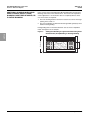
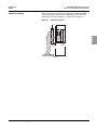
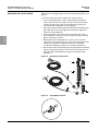
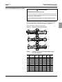
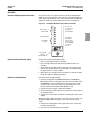
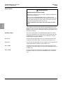
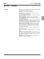
The XUSLB/XUSLDM system has a visible, red individual beam indicator
(IBI) next to each infrared beam on the receiver. This indicator illuminates
when the associated infrared beam fails to meet the conditions necessary
for the XUSLB/XUSLDM system to remain in the Machine Run state. The
IBIs are not safety critical components. A beam indicator failure will not
cause an alarm condition, and the XUSLB/XUSLDM system will continue to
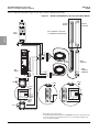
operate. See Figure 1 on page 12 for component location.
Synchronization
Synchronization between the XUSLB/XUSLDM system transmitter and
receiver is optical.
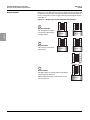
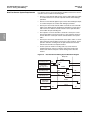
To establish synchronization the system needs to have a predetermined
number of consecutive clear beams within the first master segment. If this
requirement is not satisfied, the system will enter a Machine Stop state and
every other individual beam indicator will illuminate. When the beams are
clear, the system will re-synchronize and enter a state consistent with its
operating mode.
Once the synchronization is established, it can be maintained as long as the
required number of consecutive clear beams can be satisfied anywhere in
the system (including flex systems). See “Optical Synchronization” on
page 55.
External Device Monitoring (EDM) or
Machine Primary Control Element
(MPCE) Monitoring
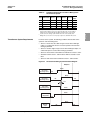
EDM/MPCE monitoring is an important safety function. It monitors the
XUSLB/XUSLDM system’s interface to the guarded machine to confirm that
the machine’s primary control elements (switching devices, such as
contactors) are responding correctly to the XUSLB/XUSLDM light curtains,
and to detect any inconsistency between the two machine EDMs/MPCEs
which prevents a stop signal from reaching the machine primary control
elements.
XUSLB without a PDM
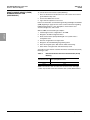
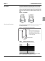
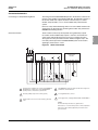
On the XUSLB (without a PDM), the EDM function is controlled through the
External EDM Select feature using the start line connections to disable or
enable the function as follows:
•
If the start line is connected to 0 Vdc at start-up, the EDM function is
disabled. The EDM line must be connected to 0 V.
•
If the start line is connected to +24 V at start-up, the EDM function is
enabled. The EDM line must be connected in series through the NC
contacts on the final switching device.
When using the start line to configure the EDM function, the manual start
input is not accessible.
XUSLDM and XUSLB with a PDM
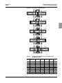
On the XUSLDM and XUSLB (with PDM), the EDM function can be
activated and deactivated using the PDM.
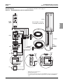
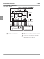
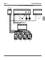
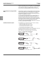
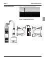
Connections for MPCE monitoring are made at the receiver (see Figure 22
on page 49). On power-up, the XUSLB/XUSLDM system looks for the
MPCE to be in the closed condition—an Off state where the contacts are
closed. When this is found, the system enters a state consistent with the
selected operating mode (see “Operating Modes” on page 16).
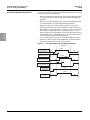
When the XUSLB/XUSLDM system enables its safety outputs (enters the
Machine Run state), it monitors the MPCE contacts for a closed-to-open
© 2008 Schneider Electric All Rights Reserved
73–EN
English
DIAGNOSTIC AND TEST FEATURES