1
XUSLB/XUSLDM Safety Light Curtain
Section 2—Product Description
SYSTEM COMPONENTS
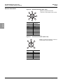
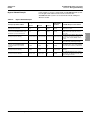
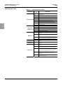
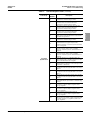
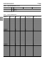
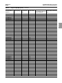
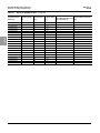
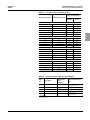
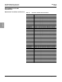
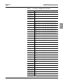
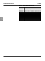
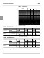
Table 2:
Item No.
A
30072-451-85
02/2008
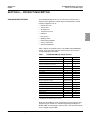
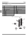
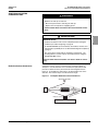
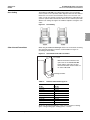
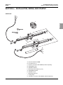
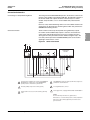
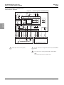
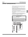
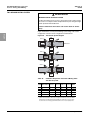
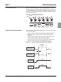
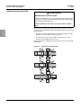
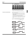
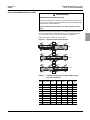
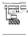
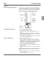
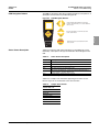
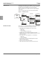
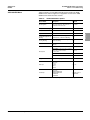
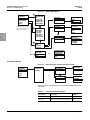
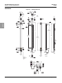
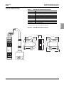
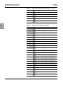
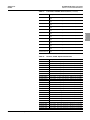
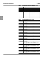
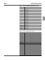
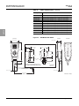
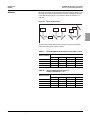
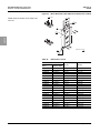
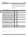
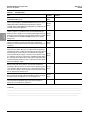
Refer to Figure 1 for the location of the components listed in Table 2.
System Components Identification
Description
Item No.
Description
Receiver
G
Transmitter
B
Individual beam indicator (one for each beam)—Red
H
Detection zone
C
Blanking active—Amber
I
Programming port for the PDM
D
Interlock or Alarm indicator—Yellow
J
Status indicator—Yellow
E
Machine Run/Stop indicator—Green/Red
K
Side mounting T-Slot
F
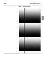
Receiver connections M-12 (male)
L
Transmitter connections M-12 (male)
English
1
+24 Vdc
1
2
0 Vdc
2
+24 Vdc
3
Ground
3
MTS
4
OSSD2
4
MTS Return
5
Start or EDM
5
Ground
6
EDM
7
Auxiliary Output
8
OSSD1
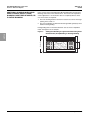
Figure 1:
0 Vdc
XUSLB/XUSLDM System Components
H
Detection
Zone
Transmitter
A
G
Receiver
K
C
D
B
E
Alternate
T-Slot
Mounting
Receiver LED
Indicators
I
4
6
5
4
8
7
1
Transmitter
LED Indicator
3
2
3
5
1
2
J
L
F
12–EN
© 2008 Schneider Electric All Rights Reserved