1
Assembly
Assembly
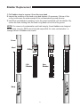
Use Figure 2, (Page 3) to identify main pump components and Figure 3, (below) to
identify O-ring locations. Detailed exploded view drawing of the upper end of the
pump are shown on pages 7 and 8.
1. See Figure 3 (below) to identify locations where O-rings and seals are to be installed
and install all O-rings and seals.
2. Connect the bladder to the pump head. The PE bladder pushes onto the pump head
barb until the bladder fully covers the barb.
3. Attach the pump head to the body by engaging the bayonet dimples into the grooves
and twisting them together until the engagement snap is felt and head and body
alignment marks line up.
4. With the pump on its side, insert the inlet check ball (same as the discharge check
ball) into the side of the pump head, then press in the inlet valve seat by pushing
with your thumb. Pre-wetting the parts with distilled water is recommended to aid
assembly
.
5. With the pump vertical, insert the discharge check ball into the top of the pump
head, place the discharge ball stop into place above the check ball, using the supplied needle nose pliers, see Figure 5, (Page 6).
6. For the push-in tubing fittings, place the thin metal lock disk in the "TOP" up position on the top of the pump head, with the lock disk edge slots lined up with the
posts on the pump head. Then place the thick, upper plate on top of the lock disk,
again with the slots and posts lined up. Finally, twist the pump cap onto the pump
head until the engagement snap is felt and the hole in the side of the pump cap lines
with the inlet port. Cover and body alignment marks will line up.
Figure 3
Discharge Seal
1/4 Tube-38677
Ball Stop 38438EP
Ball 38471
Air Tube Seal 38676
Inlet O-Ring 38470
H ead
O-R in gs
3517 2
Blad der
O-Ring
38470
Ball
38471
Inlet
38439EP
Head 38437EP
4