1
X-shooter Instrument Software
User and Maintenance Manual
Doc.
Issue
Date
Page
VLT-MAN-ITA-8000-0065
1.2
20.04.09
1 of 114
VLT Software
--X-shooter Instrument Software
User and Maintenance Manual
Doc. No.: XSH-MAN-ITA-8000-0065
Issue: 1.2
Date: 20/04/2009
Name
Prepared: P. Di Marcantonio,
P. Santin,
M. Vidali
Name
Date
Signature
20/04/2009
Date
Signature
Date
Signature
Approved: PI Board
Name
Released: H. Dekker
X-shooter Instrument Software
User and Maintenance Manual
Doc.
Issue
Date
Page
VLT-MAN-ITA-8000-0065
1.2
20.04.09
2 of 114
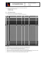
CHANGE RECORD
ISSUE
0.5
0.9
1.0
1.1
1.2
DATE
SECTION/PAGE
AFFECTED
REASON/INITIATION
DOCUMENTS/REMARKS
4/16/2009
15/06/2008
22/08/2008
All
All
All
All
All
First issue – preliminary release
Pre-PAE release
PAE release
According to PAE Review comments
End of commissioning #3
20/04/2009
X-shooter Instrument Software
User and Maintenance Manual
Doc.
Issue
Date
Page
VLT-MAN-ITA-8000-0065
1.2
20.04.09
3 of 114
TABLE OF CONTENTS
1
INTRODUCTION .............................................................................................................. 7
1.1
Purpose ................................................................................................................................................................ 7
1.2
Scope .................................................................................................................................................................... 7
1.3
Applicable Documents ......................................................................................................................................... 7
1.4
Reference Documents .......................................................................................................................................... 8
1.5
Abbreviations and Acronyms .............................................................................................................................. 9
1.6
Glossary ............................................................................................................................................................... 9
1.7
Stylistic Conventions ............................................................................................................................................ 9
1.7.1
Data Flow and Processor Model Diagrams .................................................................................................... 10
1.8
Naming Conventions .......................................................................................................................................... 10
1.9
Problem Reporting/Change Request ................................................................................................................. 10
2
OVERVIEW ..................................................................................................................... 11
2.1
Hardware architecture ...................................................................................................................................... 11
2.1.1
Devices ........................................................................................................................................................ 11
2.1.2
Computers ................................................................................................................................................... 11
2.1.3
LANs ........................................................................................................................................................... 11
2.1.4
Special connections ...................................................................................................................................... 11
2.2
Software Architecture........................................................................................................................................ 13
2.2.1
Software Modules ........................................................................................................................................ 13
2.2.2
Environments ............................................................................................................................................... 13
2.2.3
Users ........................................................................................................................................................... 15
2.2.4
Standards ..................................................................................................................................................... 15
3
INSTALLATION GUIDE .................................................................................................. 16
3.1
Requirements ..................................................................................................................................................... 16
3.1.1
Hardware ..................................................................................................................................................... 16
3.1.2
Software ...................................................................................................................................................... 16
3.2
4
4.1
Installation procedure........................................................................................................................................ 16
OPERATOR’S GUIDE ..................................................................................................... 18
Environment Start-up and Shut-down .............................................................................................................. 18
4.2
Instrument Software Start-up ........................................................................................................................... 18
4.2.1
Log-in .......................................................................................................................................................... 18
4.2.2
Telescope availability................................................................................................................................... 18
X-shooter Instrument Software
User and Maintenance Manual
4.2.3
4.2.4
Doc.
Issue
Date
Page
VLT-MAN-ITA-8000-0065
1.2
20.04.09
4 of 114
Instrument Software Start-up ........................................................................................................................ 18
Begin of operations ...................................................................................................................................... 19
4.3
Instrument Software Shut-down ....................................................................................................................... 19
4.3.1
End of operations ......................................................................................................................................... 19
4.3.2
Instrument processes shut-down ................................................................................................................... 19
4.4
User interactions during operations .................................................................................................................. 20
4.4.1
FIERA operational constraints ...................................................................................................................... 20
4.4.2
Automatic Flexure Compensation – AFC...................................................................................................... 20
4.4.3
Camera focus procedures .............................................................................................................................. 21
4.4.4
Interactive target acquisition ......................................................................................................................... 21
4.5
Instrument GUI ................................................................................................................................................. 22
4.5.1
Startup panel ................................................................................................................................................ 22
4.5.2
OS Control panel.......................................................................................................................................... 23
4.5.3
Instrument Full Status panel ......................................................................................................................... 24
4.5.4
Sensor Plot panel.......................................................................................................................................... 25
4.5.5
A&G Control panels..................................................................................................................................... 26
4.5.6
ICS Control panel......................................................................................................................................... 31
4.5.7
OS Engineering panel ................................................................................................................................... 32
4.6
User Station (TBD) ............................................................................................................................................ 33
4.7
Alarms ................................................................................................................................................................ 33
4.8
Data files location............................................................................................................................................... 33
5
PROGRAMMER'S G UIDE............................................................................................... 34
5.1
Instrument Modes.............................................................................................................................................. 34
5.2
Subsystems Identifiers ....................................................................................................................................... 34
5.3
Dictionaries ........................................................................................................................................................ 34
5.4
ICS Software Devices ......................................................................................................................................... 35
5.4.1
ICS Special devices ...................................................................................................................................... 36
5.4.2
ICS Assemblies ............................................................................................................................................ 39
5.4.3
Alarms ......................................................................................................................................................... 39
5.5
6
OS specific implementation ............................................................................................................................... 40
SETUP AND CONFIGURATION KEYWORDS ............................................................... 42
6.1
Configuration files ............................................................................................................................................. 42
6.1.1
ICS Assemblies ........................................................................................................................................... 42
6.1.2
INS keywords .............................................................................................................................................. 43
6.1.3
DCS keywords ............................................................................................................................................. 45
6.2
Sub-system specific keywords ............................................................................................................................ 45
6.2.1
AFC sub-system ........................................................................................................................................... 45
6.2.2
UVB/VIS Focus settings .............................................................................................................................. 46
6.2.3
Alarm configuration ..................................................................................................................................... 47
6.2.4
GUI configuration ........................................................................................................................................ 47
6.3
Alias files ............................................................................................................................................................ 49
X-shooter Instrument Software
User and Maintenance Manual
6.4
7
Doc.
Issue
Date
Page
VLT-MAN-ITA-8000-0065
1.2
20.04.09
5 of 114
Templates keywords .......................................................................................................................................... 49
FAQ AND TROUBLESHOOTING ................................................................................... 51
3.
Pfeiffer device initialization error ........................................................................................................................ 51
8
TEST................................................................................................................................ 52
9
REFERENCES ................................................................................................................ 53
9.1
Installation Configuration Files ......................................................................................................................... 53
9.1.1
shinsINSTALL.cfg ....................................................................................................................................... 53
9.1.2
shinsTARGET_PARANAL.cfg .................................................................................................................... 58
9.2
Configuration Files ............................................................................................................................................ 59
9.2.1
shmcfgINS_cfg ............................................................................................................................................ 59
9.2.2
shmcfgINS_OS.cfg ...................................................................................................................................... 97
9.2.3
shmcfgINS.DCS.cfg ................................................................................................................................... 101
9.2.4
shmcfgMAG_CALC.cfg ............................................................................................................................ 102
9.2.5
shmcfgAFCRef_UVB.cfg .......................................................................................................................... 103
9.2.6
shmcfgAFCRef.cfg .................................................................................................................................... 104
9.2.7
shmcfgAFCRef_NIR.cfg ............................................................................................................................ 105
9.3
Instrument Setup File ...................................................................................................................................... 106
10
TEMPLATES .............................................................................................................. 108
11
FITS FILES ................................................................................................................. 109
11.1
Example of FITS header .................................................................................................................................. 109
12
LOG FILES ................................................................................................................. 113
12.1
Operational Logs (FITS format) ..................................................................................................................... 113
X-shooter Instrument Software
User and Maintenance Manual
Doc.
Issue
Date
Page
VLT-MAN-ITA-8000-0065
1.2
20.04.09
6 of 114
Table of Figures
Figure 1 Hardware architecture........................................................................................................................................ 12
Figure 2 X-shooter software Architecture ........................................................................................................................ 14
Figure 3 Instrument Startup panel .................................................................................................................................... 22
Figure 4 OS Control panel ............................................................................................................................................... 23
Figure 5 Instrument Full Status panel............................................................................................................................... 24
Figure 6 Sensors Plot panel ............................................................................................................................................. 25
Figure 7 An example of four simultaneous sensors plots .................................................................................................. 25
Figure 8 A&G Acquisition panel ..................................................................................................................................... 26
Figure 9 Pick-object sub-panel ........................................................................................................................................ 28
Figure 10 Telescope offset sub-panel ............................................................................................................................... 29
Figure 11 Magnitude evaluation sub-panel ...................................................................................................................... 30
Figure 12 ICS Control panel ............................................................................................................................................ 31
Figure 13 OS Engineering panel ...................................................................................................................................... 32
Figure 14 Sequence diagram for the shipzt device showing its basic course. ..................................................................... 37
Figure 15 Pfeiffer reception protocol (taken from the Pfeiffer user manual) ...................................................................... 38
X-shooter Instrument Software
User and Maintenance Manual
1
Doc.
Issue
Date
Page
VLT-MAN-ITA-8000-0065
1.2
20.04.09
7 of 114
INTRODUCTION
The software described in this manual is intended to be used in the ESO VLT project by ESO and authorized external
contractors only.
While every precaution has been taken in the development of the software and in the preparation of this documentation,
ESO assumes no responsibility for errors or omissions, or for damage resulting from the use of the software or of the
information contained herein.
1.1
Purpose
This document is the User and maintenance Manual of X-shooter Instrument Control Software.
This package is fully based on VLT Instrumentation Common Software packages, such as icb (base ICS, see [RD 16] and
[RD 26]), boss (base OS, see [RD 17]), tpl (library for templates, see [RD 24]), pkgin (installation tool, see [RD 18]), ctoo
(configuration tool, see [RD 25]) and stoo (startup tool, see [RD 18]).
1.2
Scope
This document covers only the control part of the X-shooter Instrument Software. The Instrument Observation Templates
are described separately in their Reference Manual (see [AD 13]). It does not deal with other parts of the Data Flow, such as
the pipeline.
It is aimed at operators of the instrument and software developers, who are responsible for its installation and maintenance.
This document, revised and released after the Commissioning Phase, contains only operational aspects considering the
Instrument at the Telescope. It contains also references to the installation and operational aspects at the VCM at ESOGarching for test purposes.
1.3
Applicable Documents
The following documents, of the exact issue shown, form a part of this document to the extent specified herein. In the event
of conflict between the documents referenced herein and the contents of this document, the contents of this document shall
be considered as a superseding requirement.
Reference
[AD 01]
[AD 02]
[AD 03]
[AD 04]
[AD 05]
[AD 06]
[AD 07]
[AD 08]
[AD 09]
[AD 10]
[AD 11]
[AD 12]
[AD 13]
Document Number
GEN-SPE-ESO-19400-0794
VLT-SPE-ESO-10000-0011
VLT-PRO-ESO-10000-0228
VLT-SPE-ESO-10000-2723
VLT-MAN-ESO-17210-0667
VLT-SPE-ESO-17212-0001
VLT-SPE-ESO-17240-0385
VLT-ICD-ESO-17240-19400
VLT-ICD-ESO-17240-19200
XSH-SPE-ITA-8000-0043
XSH-PLA-ITA-8000-0044
XSH-PLA-ITA-8000-0050
XSH-MAN-ITA-8000-0031
Issue
3
3
2
0.9
1.2
5
4
2.6
1.3
1.1
1.0
1.1
2.0
Date
In preparation
In preparation
In preparation
14/09/2004
08/10/2001
13/01/2005
13/01/2005
17/11/1997
07/06/2000
13/01/2006
22/08/2008
30/06/2006
22/08/2008
Title
DICB - Data Interface Control Document
VLT Software Requirements Specification
VLT Software Programming Standards
VLT Requirements for Scientific Instruments
Guidelines for VLT applications.
INS Software Specification
INS Common Software Specification
ICD between VCS and Archive
ICD between VCS and OH
Instrument Software Design Description
Instrument Software Acceptance Test Plan
Instrument Software Management Plan
X-shooter Templates Reference Manual
X-shooter Instrument Software
User and Maintenance Manual
1.4
Doc.
Issue
Date
Page
VLT-MAN-ITA-8000-0065
1.2
20.04.09
8 of 114
Reference Documents
The following documents are referenced in this document.
Reference
[RD 28]
Document Number
Issue
Date
VLT-MAN-ESO-17200-0888
1.0
17/08/1995
VLT-MAN-ESO-17200-0642
4
29/04/2004
VLT-SPE-ESO-17100-3439
1
In preparation
VLT-MAN-SBI-17210-0001
3.7
05/10/2001
VLT-MAN-ESO-17210-0600
1.7
02/10/1998
VLT-MAN-ESO-17210-0669
1.6
02/10/1998
VLT-MAN-ESO-17210-0619
2.4
31/03/2004
VLT-MAN-ESO-17210-0707
1.6
30/09/1999
VLT-MAN-ESO-17210-0771
1.8
06/10/2001
VLT-MAN-ESO-17210-0770
1.8
30/09/2001
VLT-MAN-ESO-17210-0690
5
31/03/2002
VLT-MAN-ESO-17240-0853
3
26/03/2004
VLT-MAN-ESO-17240-0672
1.6
25/09/1998
VLT-MAN-ESO-13640-1388
3
31/03/2004
VLT-MAN-ESO-14100-1878
1.4
01/12/2003
VLT-MAN-ESO-17240-0934
5
31/03/2004
VLT-MAN-ESO-17240-2265
4
05/04/2004
VLT-MAN-ESO-17240-1913
4
31/03/2004
VLT-MAN-ESO-17240-2153
4
31/03/2004
VLT-MAN-ESO-17220-0737
3
28/03/2002
P.Ward, S.Mellor, Yourdon Press,
1985
J. Rumbaugh et. al., Prentice Hall,
1991
VLT-MAN-ESO-17220-1999
4
19/04/2004
VLT-MAN-ESO-17240-2240
4
31/03/2004
VLT-MAN-ESO-17240-2325
4
31/03/2004
VLT-MAN-ESO-17240-2606
3
31/03/2004
VLT-PLA-ESO-17240-2266
5
13/01/2005
VLT-MAN-ESO-17200-0908
1.4
15/02/2001
[RD 29]
XSH-TRE-ESO-6000-0106
[RD 01]
[RD 02]
[RD 03]
[RD 04]
[RD 05]
[RD 06]
[RD 07]
[RD 08]
[RD 09]
[RD 10]
[RD 11]
[RD 12]
[RD 13]
[RD 14]
[RD 15]
[RD 16]
[RD 17]
[RD 18]
[RD 19]
[RD 20]
[RD 21]
[RD 22]
[RD 23]
[RD 24]
[RD 25]
[RD 26]
[RD 27]
0.1
28/09/2005
Title
VLT Common Software Overview
VLT Common Software Installation Manual
Paranal Network/Computers Design Description
LCU Common Software User Manual
Motor Control sw User Manual API/ACI
Motor Engineering Interface User Manual
Central Control Software User Manual
On Line Database Loader User Manual
EVH User Manual
Extended CCS User Manual
Panel Editor User Manual
INS Common sw - oslx User Manual
CCD Detectors Control Software User Manual
FIERA Control Software User Manual
IRACE-DCS User Manual
Base ICS User Manual
Base OS Stub User Manual
Installation Tool for VLT Sw packages
INS Startup Tool User Manual
HOS - Sequencer User Manual
Structured Development for Real-Time Systems
Object-Oriented Modeling and Design
Broker for Observation Blocks User Manual
INS Common Software for Templates
INS Configuration tool User Manual
Base ICS GUI User Manual
Acceptance Test Plan Template Document
Tool for Automated Testing User Manual
Optical Detector Control Sw Performance
Analysis
X-shooter Instrument Software
User and Maintenance Manual
1.5
Doc.
Issue
Date
Page
VLT-MAN-ITA-8000-0065
1.2
20.04.09
9 of 114
Abbreviations and Acronyms
This document employs several abbreviations and acronyms to refer concisely to an item, after it has been introduced. The
following list is aimed to help the reader in recalling the extended meaning of each short expression:
A&G
Acquisition & Guiding
AFC
Automatic Flexure Compensation
CCS
Central Control Software
CPU
Central Processing Unit
DCS
Detector Control Software
ESO
European Southern Observatory
FITS
Flexible Image Transport Format
GUI
Graphical User Interface
HW
Hardware
ICS
Instrument Control Software
INS
Instrumentation Software Package
I/O
Input/output
IWS
Instrument Workstation
LAN
Local Area Network
LCC
LCU Common Software
LCU
Local Control Unit
MS
Maintenance Software
N/A
Not Applicable
OMT
Object Modeling Technique
OO
Object Oriented
OOD
Object Oriented Design
OS
Observation Software
RAM
Random Access Memory
SW
Software
TAT
Tool for Automated Testing
TBC
To Be Clarified
TBD
To Be Defined
TCS
Telescope Control Software
TIM
Time Interface Module
TRS
Time Reference System
UIF
(Portable) User Interface (Toolkit)
UT2
VLT Unit Telescope no. 2
VLT
Very Large Telescope
VCM
Virtual Control Model
VME
Versa Module Eurocard
WS
Workstation
1.6
Glossary
No special definition is introduced in this manual
1.7
Stylistic Conventions
The following styles are used:
bold
in the text, for commands, filenames, pre/suffixes as they have to be typed.
italic
in the text, for parts that have to be substituted with the real content before typing.
teletype
for examples.
<name>
in the examples, for parts that have to be substituted with the real content before typing.
bold and italic are also used to highlight words.
X-shooter Instrument Software
User and Maintenance Manual
1.7.1
Doc.
Issue
Date
Page
VLT-MAN-ITA-8000-0065
1.2
20.04.09
10 of 114
Data Flow and Processor Model Diagrams
Data Flow and processor Model Diagrams are based on De Marco/Yourdon notation for real-time systems [RD 20].
1.8
Naming Conventions
This implementation follows the naming conventions as outlined in [AD 03].
1.9
Problem Reporting/Change Request
The form described in [RD 02] shall be used.
X-shooter Instrument Software
User and Maintenance Manual
Doc.
Issue
Date
Page
VLT-MAN-ITA-8000-0065
1.2
20.04.09
11 of 114
2 OVERVIEW
X-shooter is a wide band (U to K) single object spectrograph for the VLT. The optimization is achieved splitting the beam
into three arms, dedicated to the UV-Blue, Visible and Near-Infrared bands. It operates at intermediate resolution (R =
4000 – 14000) and will be installed at the Cassegrain focus of UT2. A great effort has been spent to limit its weight. A
result that affects the Instrument Software is the use, for the first time, of a single FIERA controller for the two UVB and
VIS arms. This will be discussed later in this document. Another outstanding aspect of the instrument is the flexure control
and compensation. This is achieved with the use of three tilt mirrors, placed along the three beams and controlled by
piezos. This system will be illustrated and its control aspects explained in the following chapters.
This chapter gives a short overview of the instrument and its architecture.
The rest of the manual is organized as follows:
· Chapter 3 is the installation guide.
· Chapter 4 is the operator’s guide, which describes how to operate the instrument at various levels.
· Chapter 5 is the programmer’s guide, which describes in detail specific items, such as ICS devices and commands.
· Chapter 6 is the configuration guide, which describes in detail the configuration of the instrument.
· Chapter 7 contains a FAQ and troubleshooting tips specific to the instrument
· Chapter 9 contains the details of the X-shooter specific configuration files.
2.1
2.1.1
Hardware architecture
Devices
The Instrument consists of:
· 29 devices, controlled by ICS, on 2 LCUs:
q 13 motorized
q 6 calibration lamps
q 7 sensor devices
q 3 piezo systems
· 3 scientific detectors
q 1 infrared (IRACE controller)
q 2 optical (only one FIERA controller)
· 1 technical CCD camera (NG controller)
2.1.2
Computers
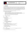
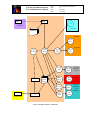
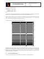
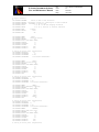
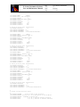
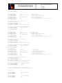
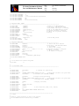
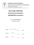
The computers on which the Instrument Software runs are shown in Figure 1:
· Instrument Workstation (node : wshoot)
· ICS LCU 1 (node : lshics1) – controls all the motorized functions
· ICS LCU 2 (node : lshics2) – controls all sensor devices, lamps and AFCs
· TCCD LCU (node : lshtccd)
· IRACE UltraSparc (node : wshnir)
· FIERA UltraSparc (node : wshubv)
2.1.3
LANs
The Instrument LAN follows the lay-out of VLT Control LANs (see [RD 03]) and is shown in Figure 1
2.1.4
Special connections
The instrument architecture does not foresee any special connection.
X-shooter Instrument Software
User and Maintenance Manual
Doc.
Issue
Date
Page
VLT-MAN-ITA-8000-0065
1.2
20.04.09
12 of 114
Telescope Area
NIR Detector
VIS Detector
UVB Detector
Front-end
Front-end
Front-end
NIR Detector
VIS Detector
UVB Detector
Back-end
Back-end
Back-end
Instrument devices
TCCD
Camera
Instrument
LCU 1
NIR Detector
LCU
Instrument
LCU 2
TCCD
LCU
UVB and VIS
Detectors LCU
Backbone
INSTRUMENT
WS
Computer Room
USER Station
USER WS
Control Room
Ethernet
Service
Connection
Point
Fast Ethernet
Fast Ethernet
switch
Direct
Link
Router
Figure 1 Hardware architecture
X-shooter Instrument Software
User and Maintenance Manual
2.2
Doc.
Issue
Date
Page
VLT-MAN-ITA-8000-0065
1.2
20.04.09
13 of 114
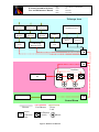
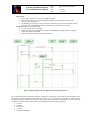
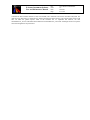
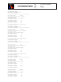
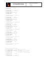
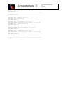
Software Architecture
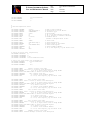
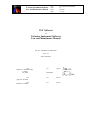
The architecture of the Control Software follows the VLT standard operational scheme and is shown in Figure 2
2.2.1
Software Modules
The X-shooter Instrument Software consists of the following cmm modules (the prefix id sh corresponds to the Instrument
ID):
Name
INS Module Platform
Description
shins
N/A
WS
Installation module for the final target configuration
dicSHOOT
N/A
WS
FITS dictionaries
shi
ICS
WS
ICS WS front-end and LCU simulator
shipan
ICS
WS
ICS stand-alone GUI
shipzt
ICS
LCU ICS AFCS piezo control special device
shibal
ICS
WS
Balzers/Pfeiffer pressure sensor control special device
fcdshdetb
DCS
WS
UVB Fiera detector configuration module
fcdshdetv
DCS
WS
VIS Fiera detector configuration module
shnir
DCS
WS
NIR Irace detector configuration module
shdnir
DCS
WS
NIR Irace detector customized Data Transfer Task
sho
OS
WS
OS Server
shortd
OS
WS
Rtd GUI for A&G acquisition
shopan
OS
WS
OS GUI
shoseq
OS
WS
Observation Template scripts
shotsf
OS
WS
Observation Template Signature Files
shmcfg
MS
WS
Instrument Configuration Files
shmseq
MS
WS
Maintenance Template scripts
shmtsf
MS
WS
Maintenance Template Signature Files
At ESO-Garching the following cmm module is also used:
Name
Location
Platform
Description
Installation and configuration module for installation and test purposes at VCM
shmgar ESO Garching
WS
operated at ESO Garching
2.2.2
Environments
The Instrument sw defines and creates the following CCS environments:
· wshoot. IWS CCS environment (see RTAPENV)
· lshics1. ICS LCU1 LCC environment.
· lshics2. ICS LCU2 LCC environment.
· lshtccd. TCCD DCS LCC environment.
· wshubv. FIERA DCS CCS environment for UVB and VIS detectors
X-shooter Instrument Software
User and Maintenance Manual
Doc.
Issue
Date
Page
VLT-MAN-ITA-8000-0065
1.2
20.04.09
14 of 114
Instrument WS
BOB
P2PP
TCS
OH WS
TCS WS
Templates
ICS LCU
1
ICS
LCU
1
OS
Archiver
OS
Server
ICS
WS
ICS
LCU
ICS LCU
2
1
TCCD
DCS
VOLAC
OLAS
Archive WS
VCSOLA
C
Data
FITS
Files
TCCD
DCS
LCU
NIR
DCS
WS
NIR
DCS
LCU
UVB
DCS
UVB
DCS
LCU
VIS
DCS
VIS
DCS
Figure 2 X-shooter software Architecture
TCCD
Detector
LCU
NIR
Detector
LCU
(IRACE)
UVB/VIS
Detectors
LCU
(FIERA)
X-shooter Instrument Software
User and Maintenance Manual
2.2.3
Doc.
Issue
Date
Page
VLT-MAN-ITA-8000-0065
1.2
20.04.09
15 of 114
Users
Two user accounts exist on the Instrument Workstation
· shootmgr
· shoot
As described below, all the installation procedures must be run as user <shootmgr>, while the Operations (start-up, shutdown, observations) are to be run as user <shoot>.
2.2.4
Standards
The Instrument Software is based on the standard packages distributed with VLT Software releases. In particular:
· TCCD DCS is based on the CCD Software (see [RD 13]).
· IR DCS is based on the IRACE Software (see [RD 15]).
· FIERA is based on the FIERA Software (see [RD 14]).
· ICS is based on the icb package (see [RD 16] and [RD 26]).
· OS is based on the BOSS package (see [RD 17]).
· Templates are based on the tpl package (see [RD 24]).
· The Instrument Software installation is based on the pkgin package (see [RD 18]).
· The Instrument Configuration is based on the ctoo package (see [RD 25]) .
· The Instrument Software Start-up/Shutdown is based on the stoo package (see [RD 19]).
X-shooter Instrument Software
User and Maintenance Manual
Doc.
Issue
Date
Page
VLT-MAN-ITA-8000-0065
1.2
20.04.09
16 of 114
3 INSTALLATION GUIDE
The installation uses the VLT standard tool pkgin (see [RD 17]).
3.1
Requirements
3.1.1
Hardware
The following computers must be available (see section 2.1.2):
· One Instrument Workstation, Linux WS, model supported by the VLT sw, see [RD 02]).
To achieve the complete functionality also the following computers must be available:
· Two LCUs for ICS
· One LCU for the TCCD
· One Linux WS for IRACE
· One Sparc LCU for FIERA
If some of them are not available the Instrument software must be configured to run in partial simulation.
3.1.2
·
Software
The Scientific Linux distribution is installed and running on the IWS, following the VLT standard installation (see [RD
02]). The 2.6.9-34 release of the kernel is running during the commissioning.
The VLTSW FEB2008 is installed as target release for the acceptance and commissioning, according to [RD 02].
SHOOT runs on CCSLite.
·
·
3.2
Installation procedure
The whole installation procedure must be executed as user shootmgr. It consists of the following steps:
I. Installation preparation
1.) Run the utility vccEnv and verify that the following CCS environments are known and correctly configured in the
ACC database:
wshoot for the instrument
lshics1 for ICS LCU 1
lshics2 for ICS LCU 2
lshtccd for TCCD DCS LCU
wshubv for the FIERA SLCU
2.) Verify that the environment variables INTROOT and INS_ROOT are defined.
% echo $INTROOT
% echo $INS_ROOT
3.) Verify that the file $HOME/.bobrc exists and is a symbolic link to $INTROOT/config/shins.bobrc. If not, run:
% ln –s $INTROOT/config/shins.bobrc $HOME/.bobrc
4.) Create an empty directory as root for the source code, e.g.:
% mkdir $HOME/SHOOT
5.) Retrieve the installation module:
% cd $HOME/SHOOT
a) For the target installation (at Paranal) :
% cmmCopy shins [<version>]
b) For the VCM installation (at ESO-Garching) :
§ Define the environment variable TARGET=CM_FULL
% cmmCopy shmgar [<version>]
X-shooter Instrument Software
User and Maintenance Manual
Doc.
Issue
Date
Page
VLT-MAN-ITA-8000-0065
1.2
20.04.09
17 of 114
II. Installation
6.) Build and install the Instrument Software
At Paranal:
a) % pkginBuild shins -step CLEAN
b) % pkginBuild shins
or
at ESO-Garching/VCM
a) % pkginBuild shmgar -step CLEAN
b) % pkginBuild shmgar
Run points (a) and (b) if the previous installation must be removed. Run only point (b) if it is a new installation or
an upgrade of a previous one (i.e. INTROOT and INS_ROOT do not need to be removed).
During the installation the following directories are created:
INSTALL
It contains logs and error logs of the installation.
ICS
It contains all ICS modules (see 2.2.1)
DCS
It contains all detector configuration modules (see 2.2.1)
OS
It contains all OS modules (see 2.2.1)
MS
It contains all MS modules (see 2.2.1), in particular shmcfg, with the whole set of
configuration files.
VLTSW_new
It contains an upgraded version of modules, if any, belonging to VLT sw releases. If
all modules as from VLTROOT are taken, this directory is missing.
COMMON
It contains ESO sw modules not officially belonging to the VLT software (e.g. the
CLIP suite)
c) At the end of the installation, check for error logs in file $HOME/SHOOT/INSTALL/pkginBuild.err.
Detector installation
During the installation all the instrument software is built. Some hooks, present in the configuration files, provide a
way to build also the detectors’ software, i.e. FIERA and IRACE code.
Ø
Ø
CLEAN phase
§ cleaning of FIERA WS INTROOT
§ cleaning of IRACE INTROOT and INS_ROOT
BUILD_MOD phase
§ Re-building of FIERA software
§ Re-building of IRACE software
Ø
BUILD_ENV phase:
§ Creation of FIERA WS environment
Ø
START_LCUENV phase
§ Start of FIERA WS environment
normally commented out
normally commented out
normally commented out
As specified above, normally the FIERA and IRACE sw are built separately, on the detector’s WS, and there is not
the need to build it every time the instrument sw is re-built. If a complete installation is needed, uncomment the
relative hooks in the file shins/config/shinsINSTALL.cfg.
X-shooter Instrument Software
User and Maintenance Manual
Doc.
Issue
Date
Page
VLT-MAN-ITA-8000-0065
1.2
20.04.09
18 of 114
4 OPERATOR’S GUIDE
This chapter is intended to give instrument operators all information they need to work with the Instrument Control
Software through its Graphical User Interface.
For Instruments operational at Paranal, after proper log-in on the User Station, the CDE menu is customized to the specific
Instrument to be operated, such that dedicated options to start-up/shutdown control processes or individual panels are
provided. The set-up of the CDE menus is under responsibility of Paranal staff.
4.1
Environment Start-up and Shut-down
The Environments are created and started during the Installation phase (see chapter 3). If, for any reason, the environments
are to be shut-down and restarted, do as follows:
As user shootmgr, type from a shell:
% cd ~/SHOOT
At Paranal:
% shinsStartEnv
% shinsStoptEnv
or
at ESO-Garching/VCM:
§ use the local installation module shmgar
§ define the environment variable TARGET=CM_FULL
% shmgarStartEnv
% shmgarStopEnv
The above commands have been implemented to provide simple commands for the User/Operator and are wrappers calling
the VLT command pkginBuild with the proper arguments. In particular, the commands to start the environments will start
all the WS environments, all the LCU environment and will install and check the scan links among them.
4.2
Instrument Software Start-up
In the following it is assumed that the installation (see chapter 3) has been successfully completed and environments are
active.
4.2.1
Log-in
In order to operate the instrument properly, the user has to log-in on all terminals on the User Station as user shoot.
Unless otherwise specified, all UNIX shell commands, described in the next sections, have to be typed on a xterm
window running on the Instrument Workstation.
After log-in, check that the environment variables needed to run properly the Instrument software are defined. To list the
environment variables that should be defined type:
% osbEnvSet SHOOT
The setting of these variables is done within the file $INTROOT/config/shins-misc-all.env. This file is automatically
sourced whenever you log-in or any new xterm is opened. Make sure that this is the case.
4.2.2
Telescope availability
If TCS is supposed to be used, check with the telescope operator that it is running and ONLINE, before starting the
Instrumentation Software.
4.2.3
Instrument Software Start-up
The system start-up is based on the common startup tool stoo (see [RD 19]).
After a new installation, or whenever some start-up configuration parameter needs to be changed, type on an xterm
window:
X-shooter Instrument Software
User and Maintenance Manual
Doc.
Issue
Date
Page
VLT-MAN-ITA-8000-0065
1.2
20.04.09
19 of 114
% shinsStartup
The Start-up GUI (see Figure 3) pops-up. This panel allows defining which sub-systems are available and at which level of
simulation they should start, in particular if they have to access the LCUs or they should simulate the LCUs functionality at
WS level. It also allows specifying which GUIs will be automatically started.
Finally, by pressing the button Start, all specified GUIs and sub-systems control processes are started. A log window shows
the various phases of the startup procedure.
When successfully completed, the log window disappears and all sub-systems should be in state STANDBY.
If any error occurs, the log window remains active and shows the reason of the failure.
Normally, once the start-up configuration is defined, the instrument can be started, or re-started, by directly typing on an
xterm window:
% shinsStart
This command has the same effect of pressing the Start button in the start-up GUI.
4.2.4
Begin of operations
Before being able to operate the instrument and take exposures, it has to be ONLINE.
On the OS Control panel (see Figure 4):
Ø
Ø
Ø
4.3
Check the global State. If it is not ONLINE, select the menu option
Instrument à ONLINE.
Please wait till the global State turns to ONLINE.
Check the Telescope. According to if it is a night or day-session connect/disconnect the Telescope to the
Instrument
Telescope à Use Telescope
à Ignore Telescope
When passing from night to day session or vice versa OS will change the link to the Telescope and
will stay in the STANDBY mode. Follow previous item instructions to put the Instrument ONLINE.
Check the Instrument Shutter. According to if it is a night or day-session open/close the Instrument Shutter.
Instrument à Open Instrument Shutter
àClose Instrument Shutter
Note then when the Instrument sw goes into STANDBY state, the Instrument Shutter is automatically
closed.
Instrument Software Shut-down
4.3.1
End of operations
After operating the instrument, whenever it is foreseen to leave it idle for long time (e.g. during daytime), the instrument
has to be brought to a safe state, also called STANDBY.
On the OS Control panel (see Figure 4):
Ø
Ø
Ø
4.3.2
Instrument à Close Instrument Shutter
Telescope à Ignore Telescope
Instrument à STANDBY
Wait till the global State turns to STANDBY.
Note then when the Instrument sw goes into STANDBY state, the Instrument Shutter is automatically closed.
Instrument processes shut-down
To shut-down all the instrument control processes, type on a xterm window:
% shinsStop
All control processes and panels are terminated.
X-shooter Instrument Software
User and Maintenance Manual
4.4
Doc.
Issue
Date
Page
VLT-MAN-ITA-8000-0065
1.2
20.04.09
20 of 114
User interactions during operations
Various sections of the Instrument Operations during instrument start-up/shut-down or Observations are performed
automatically or may require manual intervention In some cases an interactive selection/confirmation by the User/Observer
is required. They are explained in the following sections.
·
·
·
·
4.4.1
FIERA detectors startup/shutdown constraints
Automatic Flexure Compensation procedures
Camera focus during observations
Interactive target acquisition
FIERA operational constraints
The two optical detectors UVB and VIS share the same SLCU and the same electronics. To enable independent operations
on the two arms, a software concept of two cameras is used. Each camera controls one detector head together with its
associated shutter. This configuration allows an independent control of the shutters through separate PULPOs while sharing
the same FIERA controller but introduces dependencies on the order of operations on the two detectors (see [RD 29] ).
During normal operations, the following constraints apply on the startup/shutdown procedures of the two detectors
controlled by FIERA:
1. Both cameras are off
To startup the two cameras the UVB must be started first and only when ONLINE can the VIS camera be started
2. Both cameras are ONLINE
To shutdown the two cameras the VIS must be shut down first and then the UVB
3. Both cameras are off
The start-up any of the two cameras, leaving the other down, can be done always, regardless of the camera
4. One camera is already up, the other has to be enabled
This is no problem if the on-line camera is the UVB, the VIS camera may be simply started; otherwise, if the on-line
camera is the VIS then it must be first shut down and then the procedure (1) above can be followed
5. Both cameras are up
Shutting down one camera will kill some processes which are shared by the other; therefore both cameras must first
be shut down (following the case 2) and then the one required restarted.
6.
Moreover, if one of the two cameras is in simulation mode, at the start-up the one in normal mode must be started
first, so it can load all the correct parameters.
To reduce the detector electronic noise, it has been decided not to startup/shutdown the detectors at any time with the
instrument software. The Instrument software startup/shutdown will therefore leave untouched the FIERA control software,
that will be sent only to STANDBY/ONLINE states. This is achieved by use of a dedicated configuration keyword
OCS.DET1/2.STOP
F
placed in the instrument configuration file (see section 9.2.2).
If, for any reason, a FIERA detector has to be shut-down (and re-started later) the engineering panel must be used (see
Figure 13) and the recommendations described in the points 1-6 above must be manually followed. Be sure to place both
detectors ON or OFF before issuing the standard commands <shinsStart/shinsStop>.
During a <shinsStart> operation, if both the detectors are off, they are re-started following the recommendations described
in the points 1-6 above. This task is accomplished by a customized version of the start-up tool, that takes care of the starting
order of the detectors.
4.4.2
Automatic Flexure Compensation – AFC
The Automatic Flexure Compensation (AFC) sub-system consists basically in a set of three tilt-mirrors, controlled by three
piezos, that have the task to control the deviations of the light beams due to the possible flexure of the spectrographs arms
wrt the instrument backbone, keeping them always aligned with the slit entrances.
The AFC sub-system is handled by the high level software in the following way:
A first set of exposures is taken with the three arms and the NIR calibration spectral lamp LAMP2. The system setup is
· A&G slide :
SLOT
X-shooter Instrument Software
User and Maintenance Manual
Doc.
Issue
Date
Page
VLT-MAN-ITA-8000-0065
1.2
20.04.09
21 of 114
· Spectrograph arms slit : Pin_0.5
A second set of three exposures is taken with the setup
· A&G slide :
PIN
· Spectrograph arms slit : 5.0x11
A Cross-Correlation function is called (via CLIP) to compute the displacement of selected reference lines between the two
exposure sets. The result, (converted to voltage) is applied to the tilting mirrors controlling the three beams. All the voltage
levels are referred to a central position level (PARK – see section 6.2.1). The operation may be repeated (according to
operator decision) to reach a good level of correction. After this initial correction the three sub-systems are set to AUTO
mode, and continue to correct, according to a pre-defined formula. This automatic correction has a limited validity in time
(~1 hour) and for this reason the time when the first computed correction is applied is shown to the User in the OS Control
panel (see section 4.5.2 and Figure 4.
In order to minimize time losses, the whole procedure described above is run, as a rule, in the Acquisition Template after
the Telescope preset, during the time spent by the Operator to set-up the Active Optics and the Auto-Guiding.
An independent template, running only the AFC procedure, is available from the Observation Templates set to be inserted
in a complex OB in case the total exposure time is longer than the validity time of the initial correction.
At the end of the computation the results are shown to the User with a pop-up panel, offering the possibility to
· Confirm, apply the result and continue the operations
· Apply the result and re-do the second set of exposure to achieve a better correction
· Continue the operations without applying the corrections
The AFC procedure is driven by a set of configuration files (one for each instrument arm – see section 6.2.1) defining:
· The list of (x,y) coordinates to identify the reference lines in the spectra to be compared
· The coefficients for the pixel-to-voltage conversion formula.
The max-distance and window-size parameters of the cross-correlation procedure are defined (at least during the
commissioning phase, tbd) by the User from P2PP.
The parameters needed by the whole AFC procedure are defined in three configuration files:
· shmcfgAFCRef_UVB.cfg
· shmcfgAFCRef_VIS.cfg
· shmcfgAFCRef_NIR.cfg
The configuration keywords are detailed in sections 6.2.1, 9.2.5, 9.2.6, and 9.2.7.
The low-level implementation of the AFC mechanism is described in section 5.4.1.
4.4.3
Camera focus procedures
The optical cameras UVB and VIS are provided with motorized functions to adjust the focus according to the current
temperature. As a result of the tests it was observed that the VIS camera is insensitive to the temperature. The
corresponding VIS focus motor is maintained therefore in stationary position.
The control and re-focusing are implemented in the templates and enforced in an automatic way during the instrument
setup before every exposure. If the focus value to be applied is not valid (wrong temperature acquisition) then an interactive
recovery procedure is proposed to the User.
Ø
Ø
Ø
Ø
4.4.4
The current temperature is evaluated as the median of the last 20 temperature readings.
If, for any reason, the temperature reading mechanism fails, a <last good temperature> value is maintained and
proposed to the User via a pop-up panel, together with the time it was acquired. If the User confirms this value the
re-focus is applied and the operations proceed.
If the <last good temperature> value is not accepted by the User then
the User is prompted to insert a valid temperature value. The re-focus is applied and the operations proceed.
Interactive target acquisition
At the end of the acquisition template the User is prompted (by a message and an acoustic signal) to select the observation
target, i.e. to put it in the center of the slits. The A&G GUI appears (see Figure 8) and the User must pick-up the target with
the mouse. The offset from center slit is computed and the result is shown to the User in a pop-up window. The choices are:
· Apply and Continue
X-shooter Instrument Software
User and Maintenance Manual
·
·
Doc.
Issue
Date
Page
VLT-MAN-ITA-8000-0065
1.2
20.04.09
22 of 114
the offset is applied to the telescope and the acquisition template proceeds
Apply and Re-do
The offset is applied to the telescope and a new target selection is proposed
Continue
The template proceeds without applying any offset to the telescope.
With the A&G GUI active the User has also the possibility to activate from the Menu bar a sub-panel to apply small offsets
to the telescope or to apply a rotation to the Adapter./Rotator (see Figure 10 ).
At the same time, with the field displayed in the main window of the A&G panel an additional graphical tool may be
started from the Menu bar to select a target, set-up some parameters and get a rough estimation of the object magnitude (see
Figure 11). This value may be used to modify the Exposure Time in the future Observation Templates.
4.5
Instrument GUI
Some of the Instrument sub-systems offer a VLT standard GUI, e.g. the FIERA (see [RD 14]), the IRACE (see [RD 15]) and
the TCCD (see [RD 13]) stand-alone control panels. The Instrument specific GUI includes the following panels:
Ø
Ø
4.5.1
Observation GUI
· Startup panel
· OS Control panel
· Instrument Full Status panel
· Sensor Plot
· A&G Control panels
Engineering GUI
· ICS Control panel
· OS Engineering Control panel
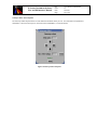
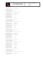
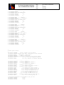
Startup panel
This panel is provided by the standard VLTSW package stoo, and provides an interactive interface to the keywords
contained in the Configuration files (i.e. shmcfgSTART.cfg). It allows to modify the availability of the Instrument subsystems and their Simulation Mode. At the end the Instrument software can be started via the START button.
This panel is to be used the first time the sw is started or when the instrument configuration (availability and/or simulation
modes) is changed. For normal operations use the command <shinsStart> (see section 4.2).
Command : % shinsStartup
Figure 3 Instrument Startup panel
X-shooter Instrument Software
User and Maintenance Manual
4.5.2
Doc.
Issue
Date
Page
VLT-MAN-ITA-8000-0065
1.2
20.04.09
23 of 114
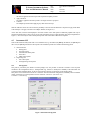
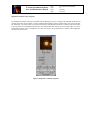
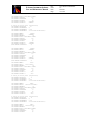
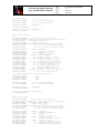
OS Control panel
It is the main Observation Control panel (see Figure 4, which refers to a simulated status). In its top section it provides the
User with the global state of the Instrument and of its sub-systems and it shows the current Instrument Mode. In the central
section it displays a detailed status of the detectors. The User is allowed only to End or Abort a running exposure. The Start
of an exposure is always controlled by the Templates, via BOB. Its right section displays a summary of the Instrument
Alarms (the status of the LEDs are the logical OR of the corresponding alarms in the Full Status panel, see 4.5.3) and the
status of the Instrument devices that are relevant to the User. At the bottom, a detailed status of the AFC sub-system is
shown. It includes the correction computed at the time the cross-correlation was run and the current values of the
extrapolated correction. Since the validity of the extrapolation of the piezos tilt is limited in time, the time of the last
computed values is also shown. Three LEDs shows the validity of the last Flexure correction.
The Menu bar Instrument options provide tools to Startup/Shutdown the OS process, to modify the state of the Instrument
(STANDBY/ONLINE), to control of the Instrument shutter and to control the link with the Telescope.
Panel type: Observation
Command : % shinsStart –panel OS_CONTROL
Figure 4 OS Control panel
X-shooter Instrument Software
User and Maintenance Manual
4.5.3
Doc.
Issue
Date
Page
VLT-MAN-ITA-8000-0065
1.2
20.04.09
24 of 114
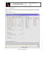
Instrument Full Status panel
This panel (see Figure 5) displays the status of the whole Instrument, prompting the User with Alarm LEDs, where
applicable. The only interactive control on it is the control of the Instrument Shutter. From the Menu bar it is possible to
start the Sensor Plot panel (see Figure 6).
Panel type: Observation
Command : % shinsStart –panel OS_STATUS
Figure 5 Instrument Full Status panel
The Xshooter OS Status panel is created dynamically on-the-fly by reading sensors description and dedicated configuration
keywords from the shmcfgINS.cfg file (see section 6.2.4). It follows the same principles as icbpan. The configuration
keywords are read during the panel startup and according to their value, the OS Status panel is built. This design proved to
be very flexible. Reading everything from a common place allowed to reflects immediately any change without touching
any line of code.
A detailed description of how things are implemented is described in the man pages of module shopan. See also section
4.7.
X-shooter Instrument Software
User and Maintenance Manual
4.5.4
Doc.
Issue
Date
Page
VLT-MAN-ITA-8000-0065
1.2
20.04.09
25 of 114
Sensor Plot panel
This panel (see Figure 6) allows the User to display the plot of a selected sensor vs. time (see Figure 7). All the sensors are
selectable.
Panel type: Engineering.
Command : % shinsStart –panel SENSORS_PLOT
Figure 6 Sensors Plot panel
Figure 7 An example of four simultaneous sensors plots
X-shooter Instrument Software
User and Maintenance Manual
4.5.5
Doc.
Issue
Date
Page
VLT-MAN-ITA-8000-0065
1.2
20.04.09
26 of 114
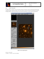
A&G Control panels
The A&G Control set of Panels (shortd) are intended to provide an interactive tool to the user during the acquisition phase,
to assist the operator in placing the object on the center of the slit or of the IFU. Please note that while the sub-system is
thoroughly named as Acquisition and Guiding only the acquisition functionality is currently defined and implemented.
Figure 8 A&G Acquisition panel
Panel type: Observation
Command : % shinsStart –panel AG_CONTROL
X-shooter Instrument Software
User and Maintenance Manual
Doc.
Issue
Date
Page
VLT-MAN-ITA-8000-0065
1.2
20.04.09
27 of 114
The main panel, inherited from rtd, provides to the User a tool to handle the Target Acquisition phase (menu X-Shooter >
Pick Object), to display various overlays indicating N and E directions, the positions of the slits and of the IFU, the
atmospheric dispersion spectrum (menu View/Hide overlays) and to allow the setup of the A&G camera. From the menu
X-shooter > Evaluate magnitude a sub-panel could be launched to allow a rough magnitude estimate of the selected object;
the menu Xshooter > Telescope offset pop-ups instead a sub-panel for offsetting the telescope in X and Y direction (unit
arcsec) and for modifying the rotator angle.
The look&feel of the AG_CONTROL panel is built following the design principles of osrtdb. A set of configuration
keywords and files (see module shortd/config and section 6.2.4) create additional buttons and output widgets used to send
command to and display results from the TCCD (start continuous loop, stop it, change integration time) and to ICS (change
A&G filter). All the rest is standard. Two additional menus (always defined in the shortd/config , Xshooter and View/Hide
overlays) were moreover added to launch specific Xshooter sub-panels and to plot several features on the main display
window.
The overlays that can be plotted are the following (see section 6.2.4 for the definition of the configuration keywords):
· Instrument slits and their appearance (each Xshooter slit has this set defined but only few of them are displayed);
· Instrument IFU and its appearance;
· N/E arrows;
· Atmospheric dispersion direction; the atmospheric dispersion direction is shown by an arrow. Perpendicular to the
arrow, three additional segments are shown, with red, green and blue color. Their separation represent the amount
of the atmospheric dispersion for the central wavelength of the three arms (B=405 nm, V=633 nm, IR=1310 nm)
respect to the central wavelength of the chosen A&G filter.
All the drawings are attached to OLDB and image events. Every time a new image is displayed all the positions for the
drawings are recomputed. In particular, depending on the chosen A&G filter, every slit is displaced respect to the
original position (see keywords above) for an amount that depends on the current value of the atmospheric dispersion
corrections and on the small misalignment due to the filter presence.
X-shooter Instrument Software
User and Maintenance Manual
Doc.
Issue
Date
Page
VLT-MAN-ITA-8000-0065
1.2
20.04.09
28 of 114
Pick-Object, A&G sub-panel
The pick-object subpanel, inherited from RtdImagePick , is used during acquisition, to compute the centroid of the object.
The computed coordinates (X position and Y position) are simply stored in the OLDB and are processed then by the
acquisition template, which in turn converts them in the appropriate α and δ offsets required to center the object on the
slits.
Figure 9 Pick-object sub-panel
X-shooter Instrument Software
User and Maintenance Manual
Doc.
Issue
Date
Page
VLT-MAN-ITA-8000-0065
1.2
20.04.09
29 of 114
Telescope offset, A&G sub-panel
The Telescope offset sub-panel allows to send dedicated commands directly to TCS. Two commands are implemented:
OFFSADG, to move the telescope in X and Y direction and OFFSROT, to rotate the Rotator.
Figure 10 Telescope offset sub-panel
X-shooter Instrument Software
User and Maintenance Manual
Doc.
Issue
Date
Page
VLT-MAN-ITA-8000-0065
1.2
20.04.09
30 of 114
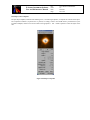
Magnitude evaluation, A&G sub-panel
The Magnitude Evaluation sub-panel is inherited from the RtdImagePick class. It computes the magnitude of the selected
(picked) object based on the number of counts summed within the “object aperture radius” (radius can be set by the slide
bar, bottom left). The actual counts are corrected (subtracted) by the background estimated as a median of the counts within
a locus of points set by the “background inner and outer radius” (slide bars, bottom center and bottom right). To convert
background subtracted counts to magnitude, zero points are needed. All the parameters are defined with configuration
keywords (see section 6.2.4).
Figure 11 Magnitude evaluation sub-panel
X-shooter Instrument Software
User and Maintenance Manual
4.5.6
Doc.
Issue
Date
Page
VLT-MAN-ITA-8000-0065
1.2
20.04.09
31 of 114
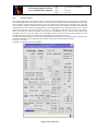
ICS Control panel
This panel (see Figure 12) provides a full control on all the Instrument devices, including simulation mode, states, position,
status, etc. It allows the User to enter physical or engineering units. It is based on the ESO standard tool icbpan (see [RD
26]).
Panel type: Engineering.
Command : % shinsStart –panel ICS
Figure 12 ICS Control panel
X-shooter Instrument Software
User and Maintenance Manual
4.5.7
Doc.
Issue
Date
Page
VLT-MAN-ITA-8000-0065
1.2
20.04.09
32 of 114
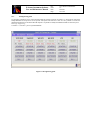
OS Engineering panel
It is the basic engineering tool to control the Instrument sub-systems processes (see Figure 13). Each section controls the
Startup/Shutdown of the processes of the specific sub-system and controls its state. It is also possible to activate the
dedicated stand-alone GUI. From the Menu bar Options it is possible to modify the Simulation Mode of each sub-system.
Panel type: Engineering
Command : % shinsStart –panel OS_ENGINEERING
Figure 13 OS Engineering panel
X-shooter Instrument Software
User and Maintenance Manual
4.6
Doc.
Issue
Date
Page
VLT-MAN-ITA-8000-0065
1.2
20.04.09
33 of 114
User Station (TBD)
The GUIs distribution on the User Station screens will be defined at Paranal.
4.7
Alarms
Alarms/warning are displayed on the OS Status panel (see Figure 5) by means of LED widgets. They become green when
a sensor value (or a digital bit) is within a valid operational status range. They become red when the value is outside valid
limits. The same information is displayed by the ESO standard CCS alarm GUI alrmDisplay. See also section 5.4.3.
4.8
Data files location
All data files used and/or generated by the Instrument Software are located under $INS_ROOT as follows:
· Configuration files:
$INS_ROOT/SYSTEM/COMMON/CONFIGFILES
· Image FITS files, results of exposures:
$INS_ROOT/SYSTEM/DETDATA
· Setup files:
$INS_ROOT/SYSTEM/COMMON/SETUPFILES/<type>
<type> is one of the following: REF, INS, DET, TARG
· Template Signature File:
$INS_ROOT/SYSTEM/COMMON/TEMPLATES/TSF
· Observation Block Description files:
$INS_ROOT/SYSTEM/COMMON/TEMPLATES/OBD
They all comply with ESO standards for the Instrumentation software.
X-shooter Instrument Software
User and Maintenance Manual
Doc.
Issue
Date
Page
VLT-MAN-ITA-8000-0065
1.2
20.04.09
34 of 114
5 PROGRAMMER'S GUIDE
This part of the document provides a description of the programmatic interface of the X-shooter Instrument Software.
5.1
Instrument Modes
SHOOT defines the following modes:
·
·
·
·
5.2
SLITSPEC. Its purpose is to take spectra in Slit Mode with all three arms.
IFUSPEC. Its purpose is to take spectra in IFU Mode with all three arms.
SLITSPEC and IFUSPEC modes involve all subsystems: ICS, FIERA, IRACE, TCCD and TCS.
Independent exposures, one for each arm (UVB, VIS and NIR), can be executed both in a semi-parallel asynchronous
way (i.e. the exposures on the three detectors are started sequentially, as soon as an arm is idle, to optimize the use of
the instrument), and in a parallel synchronous way (i.e. the exposures are started at different times in order to make
coincide the mid exposure time). See [AD 10].
IMAG. Its purpose is to take images with the TCCD of the A&G subsystem. It has no main scientific goals, but it is
intended to give to the observer a first look of the field and to give a preliminary guess of the magnitude of unknown
objects.
Subsystems involved are ICS, TCCD and TCS.
CALIB. Its purpose is to tag all the calibration images.
The subsystems involved depend on the particular calibration task.
Subsystems Identifiers
OS must be able to associate one or more sub-systems to each short-FITS keyword associated to a SETUP command. The
filtering criteria are defined in the configuration file $INS_ROOT/SYSTEM/COMMON/CONFIGFILES/shmcfgINS.cfg.
The table below provides a summary.
Subsystem
OS
ICS
FIERA
SHDETB
FIERA
SHDETV
IRDCS
SHDETR
TCCD
SHTCCD
TCS
5.3
FITS Prefix
OCS
INS
DET1
DET2
DET3
DET4
TEL
Dictionaries
The Instrument Software uses the standard VLT dictionaries to handle setup keywords and to create FITS files with proper
header: Moreover, the following dictionaries, specific to X-shooter, have been created
· ESO-VLT-DIC.SHOOT_ICS for the keywords belonging to the ICS sub-system
· ESO-VLT-DIC.SHOOT_DCS for the special keywords belonging to the SHOOT DCS sub-system
· ESO-VLT-DIC.SHOOT_OS for the special keywords belonging to the SHOOT OS sub-system
· ESO-VLT-DIC.SHOOT_CFG for the special keywords belonging to the instrument specific configuration
All instrument specific dictionaries are contained in module dicSHOOT. The X-shooter specific keywords are described in
Chapter 6.
X-shooter Instrument Software
User and Maintenance Manual
Doc.
Issue
Date
Page
VLT-MAN-ITA-8000-0065
1.2
20.04.09
35 of 114
After installation, the dictionaries can be found in one of the following directories
$INS_ROOT/SYSTEM/Dictionary
$INTROOT/config
$VLTROOT/config
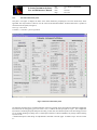
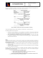
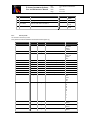
5.4
ICS Software Devices
The ICS Software devices are defined in the configuration file
·
$INS_ROOT/SYSTEM/COMMON/CONFIGFILES/shmcfgINS.cfg:
#
1
2
3
4
5
6
7
8
9
10
11
12
13
14
15
16
17
18
19
20
21
22
23
24
25
26
27
28
29
Name
Insh
cals
spl1
spl2
ffl1
ffl2
ffl3
Ffl4
Aags
Afil
adc1
adc2
adc3
adc4
Tms
dis1
dis2
ccc1
Bal
afcs1
afcs2
afcs3
Bss
Bfs
Vss
Vfs
Nss
Cryo
Lake
Description
Instrument shutter
Calibration mirror slide
ThAr lamp
Ar/Kr/Ne/Xe lamp
UVB low D2 lamp
UVB high lamp
VIS FF lamp
NIR FF lamp
A&G slide
A&G filter wheel
UVB ADC wheel #1
UVB ADC wheel #2
VIS ADC wheel #3
VIS ADC wheel #4
Temperature sensor
Digital Sensor
Digital Sensor
Cooling control sensor 1
NIR Pressure Sensor
Flexure comp. UVB
Flexure comp. VIS
Flexure comp. NIR
UVB slit
UVB camera focus
VIS slit
VIS camera focus
NIR slit wheel
NIR Cryostat Sensor
NIR Head Sensor
Positions
OPEN/CLOSED
discrete
ON/OFF
ON/OFF
ON/OFF
ON/OFF
ON/OFF
ON/OFF
discrete
discrete
continuous
continuous
continuous
continuous
N/A
N/A
N/A
N/A
N/A
N/A
N/A
N/A
discrete
continuous
discrete
continuous
discrete
N/A
N/A
Motor
Axis
circular
linear
N/A
N/A
N/A
N/A
N/A
N/A
linear
circular
circular
circular
circular
circular
N/A
N/A
N/A
N/A
N/A
N/A
N/A
N/A
linear
linear
linear
linear
circular
N/A
N/A
FITS Prefix
INS.OPTI1
INS.MIRR1
INS.LAMP1
INS.LAMP2
INS.LAMP3
INS.LAMP4
INS.LAMP5
INS.LAMP6
INS.OPTI2
INS.FILT1
INS.ADC1
INS.ADC2
INS.ADC3
INS.ADC4
INS.SENSOR1
INS.SENSOR2
INS.SENSOR3
INS.SENSOR4
INS.SENSOR5
INS.TILT1
INS.TILT2
INS.TILT3
INS.OPTI3
INS.FOCU1
INS.OPTI4
INS.FOCU2
INS.OPTI5
INS.SENSOR6
INS.SENSOR7
ICB Class
icbMOT_OPTI
icbMOT_MIRROR
icbLAMP
icbLAMP
icbLAMP
icbLAMP
icbLAMP
icbLAMP
icbMOT_OPTI
icbMOT_FILTER
icbMOT_ADC
icbMOT_ADC
icbMOT_ADC
icbMOT_ADC
icbSEN_ESTERS
icbSEN_DIGITAL
icbSEN_DIGITAL
icbSEN_COOLING
Special device
Special device
Special device
Special device
icbMOT_OPTI
icbMOT_POS
icbMOT_OPTI
icbMOT_POS
icbMOT_OPTI
icbSEN_LAKESHORE
icbSEN_LAKESHORE
LCU
1
1
2
2
2
2
2
2
1
1
1
1
1
1
2
2
2
2
2
2
2
2
1
1
1
1
1
2
2
Some remarks:
· All motorized devices use ESO standard motion control (Maccon) and amplifier boards.
· Devices bfs and vfs use a linear formula for user units versus encoder units conversion.
· Device tms is connected to the hw device ESTERS DC48 (RS-232)
· Devices ccc1 is connected to the ESO standard cabinet cooling hw device (RS-232)
· After the integration period at ESO premises in Garching it was verified and agreed that the 2nd standard ESO cabinet
cooling unit (ccc2) is no longer needed. This device is therefore at present, dropped from the list.
· Device dis1, dis2 are connected to the ESO standard MEN M58 digital I/O board
X-shooter Instrument Software
User and Maintenance Manual
5.4.1
Doc.
Issue
Date
Page
VLT-MAN-ITA-8000-0065
1.2
20.04.09
36 of 114
ICS Special devices
ICS WS special behaviour
A WS special device class is foreseen to handle non-standard camera focus behavior for the VIS and UVB spectrograph. It
takes care to move the focus slide for the right amount, depending on the current temperature before each exposure. The
temperature sent to the sw device is computed as the median of the last 20 temperature readings; in case of anomalies (i.e.
anomalous temperature reading, broken sensor etc.), a warning/alarm is written in the OLDB and logged. At the FDR (see
[AD 10]) it
was agreed that the refocus mechanism is handled by template. The template checks the
<alias>focusUvbTemp.alarm (and <alias>focusVisTemp.alarm depending on the arm) attribute before sending the
keyword INS.FOCUi.UPDATE T: if alarm is set, a pop-up window is raised showing the last_good temperature together
with the information about when this was acquired, giving the possibility either to send the proposed value or to adjust it. If
the last_good is not available (for instance not computed yet) a default value is proposed. If the alarm is not set, the median
value of the last 20 temperature reading is sent using the keywords: INS.FOCUi.TEMP 0 INS.FOCUi.POS <median
value>.
The threshold values are set by means of configuration keywords (see section 6.2.2).
The following special classes handle the refocus mechanism:
· shiINS_FOCUS: this class, derived from ic0INS_MOTOR, takes care of focus adjustment, depending on the
current temperature before each exposure. The temperature sent to the device is computed as the median of the last
20 temperature readings; in case of anomalies (i.e. anomalous temperature reading, broken sensor etc.), an error
will be returned.
· shiINS_TEMP: this class computes the median of the last temperature readings stored in a 20-record table
<alias>focusUvbTemp.dataCollection (<alias>focusVisTemp.dataCollection). If the table is not full (i.e. the
instrument was just switched on), only the available data are used for the computation. The computation is
performed based on a database event using a callback mechanism implemented in shiServer.C. Whenever the
sensor value is updated on the WS OLDB the median is computed; if the median is within the valid range, the
value is stored in two attributes: medianTemp and last_good. If the median is not in the valid range the attribute
alarm is set.
At the FDR it was proposed to use the standard historian tool to collect temperature values. But exhaustive tests during the
implementation showed that the historian suffers from severe failures, especially losing events. This was formally
described in an SPR (VLTSW20070106). At the time of writing the SPR is still not solved and it was decided therefore to
implement a custom table (i.e. <alias>focusUvb(Vis)Temp.dataCollection) to handle median computation.
ICS LCU special devices
shibal
None of the pressure sensors standard devices supported by icb fulfills the requirements in terms of accuracy and
operability in a cryogenic environment. For this reason, a Pfeiffer (formerly Balzers) pressure controller, not supported by
icb, has been chosen to monitor the NIR arm cryostat pressure values. The software module responsible of the device
handling is shibal.
The Pfeiffer special device functionality is implemented in two dedicated LCU processes:
· shibalServer , which receives commands from the standard ic0lcuServer task, executes the corresponding actions
and returns the reply.
· shibalMonitor , which periodically monitors the status of the hardware associated to the device
The Hardware interface is represented by the VME MEN M36 board and the VME ISER 12 board.
The Software interfaces are:
· MEN M36 driver for the Balzers device.
· ISER 12 driver for the serial connection.
· Command Interface to the process ic0lcuServer.
· OLDB attributes, scanned to the IWS.
The short FITS prefix for device BAL is INS.SENS60.VAL.
The following “basic course” describe the operations of the Balzers special device:
X-shooter Instrument Software
User and Maintenance Manual
Doc.
Issue
Date
Page
VLT-MAN-ITA-8000-0065
1.2
20.04.09
37 of 114
Basic Course:
· Device server shibalServer receives a STANDBY command
· Device server shibalServer reads the OLDB and depending on the simulation level spawns the
monitoring task shibalMonitor
· The monitoring task reads every 60 sec (this value is hard-coded) the pressure from the MEN device,
writes the value in the OLDB and issues an operational log containing the current value
Exception Course: read from MEN failed
· Try once more as recovery procedure
· If failure persists, issue an operational log of type UNFORESEEN and flag the failure by writing an
illegal value (9999) in the OLDB
· Keep the same state and keep the monitoring task active
Figure 14 Sequence diagram for the shipzt device showing its basic course.
The communication between the Pfeiffer and the ICS software is done through a serial interface. When the Pfeiffer is put
into operation, it starts transmitting measured values in intervals of 1 s. As soon as the first character is transferred to the
TPG 261, the automatic transmission of measured values stops. The data transmission is bi-directional, i.e. data and control
commands can be transmitted in either direction. The configuration of the serial port is as follows:
· 1 start bit
· 8 data bits
· No parity bit
· 1 stop bit
· No hardware handshake
X-shooter Instrument Software
User and Maintenance Manual
Doc.
Issue
Date
Page
VLT-MAN-ITA-8000-0065
1.2
20.04.09
38 of 114
Messages are transmitted to the Pfeiffer as ASCII strings in the form of mnemonic operating codes and parameters. All
mnemonics comprise three ASCII characters. The protocol is shown in the Figure 15.
Figure 15 Pfeiffer reception protocol (taken from the Pfeiffer user manual)
<ENQ> means ENQUIRY (Request for data transmission); its decimal value is 10, its HEX value is 05.
The following commands are sent to the device:
·
·
If the device is still not initialized (i.e. in state LOADED) and a STANDBY is issued then the command TID
(Transmitter identification), followed by the command UNI, 0 (Unit pressure; set pressure unit to mbar) is sent.
This is used to verify that the communication with the device could be established;
Once in STANDBY and not in simulation, then every period of time (typically 60 sec), the pressure value is asked
by sending the command PR1 (Pressure measurement (measurement data) gauge 1). The return value is the
pressure value in the current unit.
shipzt
According to the results of the FEA, a correction system is required in order to fulfill the requirements of maximum slit
displacement induced by backbone flexures. An active flexure compensation system, based on piezoelectric actuators (one
per spectrograph arm) was foreseen. The software module responsible of the flexure handling is shipzt and is implemented
in two dedicated LCU processes:
· shipztServer, which receives commands from the standard ic0lcuServer task, executes the corresponding actions
and returns the reply.
· shipztMonitor, which periodically monitors the position of the telescope/instrument and executes corresponding
actions to compensate for the flexures.
The basic operations of the AFC special devices is described in great detail in [AD 10]. It uses three hardware I/f
represented by the VME MEN M37 (DAC converter), VME MEN M36 (ADC converter) and VME MEN M58 (digital)
boards and the basic course is the following:
· Device server shipztServer receives a STANDBY command:
o open the communications with the MEN modules;
o apply the reference voltage and issues an operational log containing the current value;
o switch on the piezo amplifier (by rising a digital signal).
Note: These steps during STANDBY are required to preserve the lifetime of the piezo system.
· Device server shipztServer receives an ONLINE command:
X-shooter Instrument Software
User and Maintenance Manual
·
·
Doc.
Issue
Date
Page
VLT-MAN-ITA-8000-0065
1.2
20.04.09
39 of 114
Device server shipztServer receives a SETUP command:
o depending on the passed MODE parameter the following case are handled:
Ø PARK – deactivates the monitoring task and apply a fixed value (read from the OLDB)
corresponding to the middle position;
Ø STAT – stops the monitoring task and maintain the current position;
Ø REF – deactivates the monitoring task and moves the tables in a fixed position read in
the OLDB, corresponding to the position required for the alignment of the system
without flexures (i.e. when the telescope is in zenith position);
Ø AUTO – activates the monitoring task shipztMonitor, which periodically calculate and
applies the corrections. The task is spawned only once to avoid memory fragmentation
and is deleted only when the device is sent to OFF, again to avoid memory
fragmentation; when the MODE changes it will be just stopped. The corrections are
calculated according to a formula defined by Filippenko (PASP 94, 1715-72, 1982),
based on the current telescope/instrument position. The current telescope/instrument
position is passed to the LCU using the same mechanism as for the ADC. The required
telescope data are scanned from the telescope WS and they are sent to the LCU using
the standard mechanism provided by icb.
Other setup keywords implemented for these devices are:
Ø INS.TILTi.AXISX – send a given correction to the X axis of the piezo
Ø INS.TILTi.AXISY – send a given correction to the Y axis of the piezo
All the required parameters (i.e. conversion factor, reference voltage for the middle and zenith position etc.) are stored in
the shmcfgINS.cfg file, where they can be modified (see section 6.2.1 for the definition of the keywords).
It is foreseen that the device will operate in open loop. A feedback is read to get the position in X and Y. Knowing the
correction to be applied and having this feedback, it is checked that the applied value actually does the required correction.
If not, an error is issued. Once the position is reached, the feedback is not checked anymore.
The description given above is meant to describe the low level behaviour. The overall procedure to estimate the required
correction parameters is performed by the high-level software (CLIP I/f and templates) and is described in section 4.4.2.
5.4.2
ICS Assemblies
The ICS assemblies are defined in the configuration file
$INS_ROOT/SYSTEM/COMMON/CONFIGFILES/shmcfgINS.cfg:
#
5.4.3
1
Name
INS.SENSORS
Description
All sensor devices
2
INS.MODE
Instrument mode
3
INS.PATH
Light path
4
INS.LAMP
All lamps
5
INS.ADCB
Controls UVB ADC1 and ADC2
6
INS.ADCV
Controls VIS ADC3 and ADC4
Commands
STATUS
SETUP
STATUS
EXPSTRT
EXPEND
STATUS
SETUP
SETUP
SETUP
Values
See 5.1
SLITSPEC
IFUSPEC
IMAG
CALIB
<blank>
OFF
OFF
AUTO
OFF
AUTO
Alarms
Alarms/warnings are defined in the OLDB using the standard classes provided by the CCS module alrm (see shiEnv2.db).
Alarms are triggered only if the monitoring is active. CCS OLDB calculation engine functionality is used to achieve this.
To define the trigger conditions (i.e. min and max allowed values for normal condition) a custom OLDB class was
implemented (shiALARM.class):
X-shooter Instrument Software
User and Maintenance Manual
Doc.
Issue
Date
Page
VLT-MAN-ITA-8000-0065
1.2
20.04.09
40 of 114
CLASS BASE_CLASS shiALARM
BEGIN
ATTRIBUTE logical enabled
ATTRIBUTE double minVal
ATTRIBUTE double maxVal
END
For each sensor (to be monitored) an instance of this class is created in the OLDB and the corresponding values are filled
by means of a set of configuration keywords defined in shmcfgINS.cfg and described in section 6.2.3.
Besides, using the standard CCS alrm tools, alarms are also displayed on the OS Status GUI (see Figure 4) using LED
widgets. This LEDs turn RED when the corresponding sensor value is outside the valid range (i.e. value < [.minVal] and
value > [.maxVal]). The LED configuration is described in section 6.2.3.
Tentative list of analog sensors, with the min and max threshold values:
ESTERS station
UVB Camera temp. (C)
UVB Prism temp. (C)
UVB Bench temp. (C)
VIS Camera temp. (C)
VIS Prism temp. (C)
VIS bench temp. (C)
UVB cyo temp. (C)
VIS cryo temp. (C)
NIR cryo temp. (C)
Ambient temp. (C)
BB UVB ADC temp. (C)
Min threshold
0
0
0
0
0
0
0
0
0
0
0
Max Threshold
20
20
20
20
20
20
20
20
20
20
20
NIR sensors
OB Cover tank (K)
OB Prism (K)
OB Corrector lens (K)
Cryo cold plate (K)
Cryo radiation shield (K)
OB cover telescope (K)
CCD Copper bar (K)
NIR ccd head temp. (K)
NIR pressure. (mbar)
UVB fiera chip
VIS fiera chip
Min threshold
103
103
103
103
0
103
0
0
1e-9
134
134
Max Threshold
107
107
107
107
110
107
83
82
1e-5
136
136
Some digital signal (coming from the hw ELE) seems inverted to what is expected: 0 means alarm and 1 means no alarm.
For consistency with other sw alarms, we use the CE to invert this. There is a LED widget (on the OS Status panel)
connected to every digital signal (see for instance <alias>DIS1.disAlarm0, <alias>DIS2.dis2Alarm0 etc.), which turns RED
when the signal becomes 1 and turns green when the signal becomes 0. The same warning/alarms are reported also on the
standard CCS alrmDisplay (see shiEnv2.db).
5.5
OS specific implementation
X-shooter OS is fully based on BOSS. Only a deviation from standard behavior has been implemented.
X-shooter Instrument Software
User and Maintenance Manual
Doc.
Issue
Date
Page
VLT-MAN-ITA-8000-0065
1.2
20.04.09
41 of 114
X-shooter has three scientific detectors (UVB, VIS and NIR) and a technical CCD used for the A&G sub-system. The
A&G TCCD is quite always in continuous loop, showing the telescope field to the user. The exposure status of the TCCD
does not affect the global exposure status of the X-shooter OS. To implement this behavior, the class
shoINTERFACE_TCCD is inherited from the BOSS class bossINTERFACE_TCCD and disentangles the TCCD exposure
status from the global OS exposure status.
X-shooter Instrument Software
User and Maintenance Manual
Doc.
Issue
Date
Page
VLT-MAN-ITA-8000-0065
1.2
20.04.09
42 of 114
6 SETUP and CONFIGURATION KEYWORDS
The files involved in the definition and description of the configuration keywords are:
· Dictionaries
· Configuration files
· Setup files
· FITS files’ headers
All the above files, in the case of X-shooter comply with the ESO standards. Only the X-shooter instrument specific
extensions are listed in this section. All the setup and configuration keywords listed below are defined in one of the specific
X-shooter dictionaries
·
·
·
·
ESO-VLT-DIC.SHOOT_ICS for the keywords belonging to the ICS sub-system
ESO-VLT-DIC.SHOOT_DCS for the special keywords belonging to the SHOOT DCS sub-system
ESO-VLT-DIC.SHOOT_OS for the special keywords belonging to the SHOOT OS sub-system
ESO-VLT-DIC.SHOOT_CFG for the special keywords belonging to the instrument specific configuration
All the ESO-VLT standard keywords are defined in the ESO standard dictionaries stored in $VLTROOT/config.
6.1
Configuration files
The files containing information related to the instrument configuration are:
· shmcfgCONFIG.cfg. It is the master file for the ctoo tool and contains basic information about which other
files are involved and for what purpose.
· shmcfgINS.cfg. It contains most of the Instrument configuration information (ICS related)
· shmcfgINS_DCS.cfg. It contains the Instrument configuration information related to DCS. The clip camera
name is defined here.
· shmcfgINS_OS.cfg. It contains most of the Instrument configuration information. (OS related)
· shmcfgSTART.cfg. It contains only the startup information (e.g. which subsystems are available and at which
level of simulation they should work) and is used by shinsStartup, shinsStart and shinsStop, all based on the
Startup Tool stoo (see [RD 19]).
· shmcfgTARGET_<target>.cfg. It contains the configuration information for a specific target (e.g. for the VLT
Control Model).
· shmcfgTEST.cfg. It contains the configuration information for running self test scripts (see manual page of
inscSelfTest)
· shmcfg*M.dbcfg. Each of these files contains the configuration of one motor controlled by ICS. They have
been created using the VLT Motor Engineering Interface Tool (motei, see [RD 06]).
· shmcfgMAG_CALC.cfg It contains zero point corrections for magnitude estimation.
· shmcfgAFCREF_<arm>.cfg. It contains the reference line information for the cross-correlation computation
for the flexure compensation
· Other *.cfg and *.dbcfg files are created and used by the standard DCS and Real-Time Display (rtd/irtd)
packages.
6.1.1
ICS Assemblies
$INS_ROOT/SYSTEM/COMMON/CONFIGFILES/shmcfgINS.cfg
1
#
Name
INS.SENSORS
All sensor devices
Description
2
INS.MODE
Instrument mode
3
INS.PATH
Light path
Commands
STATUS
SETUP
STATUS
EXPSTRT
EXPEND
STATUS
Values
See 5.1
SLITSPEC
IFUSPEC
IMAG
X-shooter Instrument Software
User and Maintenance Manual
6.1.2
4
INS.LAMP
All lamps
5
INS.ADCB
Controls UVB ADC1 and ADC2
6
INS.ADCV
Controls VIS ADC3 and ADC4
Doc.
Issue
Date
Page
VLT-MAN-ITA-8000-0065
1.2
20.04.09
43 of 114
SETUP
SETUP
SETUP
CALIB
<blank>
OFF
OFF
AUTO
OFF
AUTO
INS keywords
OS and ICS treat these keywords.
$INS_ROOT/SYSTEM/COMMON/CONFIGFILES/shmcfgINS.cfg
Setup keyword
INS.MODE
Device
(assembly)
Units
N/A
INS.SHUT1.ST
INS.MIRR1.NAME
insh
cals
deg
mm
INS.LAMP1.ST
INS.LAMP2.ST
INS.LAMP3.ST
INS.LAMP4.ST
INS.LAMP5.ST
INS.LAMP6.ST
INS.LAMP
INS.OPTI2.NAME
spl1
spl2
ffl1
ffl2
ffl3
ffl4
(assembly )
aags
N/A
N/A
N/A
N/A
N/A
N/A
N/A
mm
INS.FILT1.NAME
afil
deg
INS.ADC1.MODE
adc1
deg
INS.ADC2.MODE
adc2
deg
INS.ADC3.MODE
adc3
deg
Description
Instrument mode
Values
SLITSPEC
IFUSPEC
IMAG
CALIB
Instrument shutter - OPEN/CLOSE T/F
Calibration Mirror Slide
Tel
ThAr_D2
Sphere
AFC
ThAr – UVB/VIS spectral lamp
T/F
ArKrNeXe – NIR spectral lamp
T/F
D2 – UVB Low FF
T/F
UVB High FF
T/F
VIS FF
T/F
NIR FF
T/F
Turn OFF all lamps
OFF
A&G slide
MIR
PIN
SLOT
PEL
IFU
A&G filter
FREE
u’
g’
r’
i’
z’
U
B
V
R
I
UVB ADC #1
OFF
AUTO
UVB ADC #2
OFF
AUTO
VIS ADC #1
OFF
AUTO
X-shooter Instrument Software
User and Maintenance Manual
Doc.
Issue
Date
Page
VLT-MAN-ITA-8000-0065
1.2
20.04.09
44 of 114
INS.ADC4.MODE
adc4
deg
VIS ADC #1
INS.ADCB.MODE
(assembly)
N/A
UVB ADC mode
INS.ADCV.MODE
(assembly)
N/A
VIS ADC mode
INS.TILT1.MODE
afcs1
N/A
AFC UVB piezo
INS.TILT2.MODE
afcs2
N/A
AFC VIS piezo
INS.TILT3.MODE
afcs3
N/A
AFC NIR piezo
INS.TILT1.AXISX
INS.TILT1.AXISY
INS.TILT2.AXISX
INS.TILT2.AXISY
INS.TILT3.AXISX
INS.TILT3.AXISY
INS.OPTI3.NAME
afcs1
pix
AFC UVB piezo
OFF
AUTO
OFF
AUTO
OFF
AUTO
AUTO
REF
PARK
STAT
AUTO
REF
PARK
STAT
AUTO
REF
PARK
STAT
Any float number
afcs2
pix
AFC VIS piezo
Any float number
afcs3
pix
AFC NIR piezo
Any float number
bss
mm
UVB slit
INS.FOCU1.POS
INS.OPTI4.NAME
bfs
vss
C (Celsius) UVB Focus position
mm
VIS slit
INS.FOCU2.POS
INS.OPTI5.NAME
vfs
nss
C (Celsius) VIS Focus position
Deg
NIR slit
0.5x11
0.8x11
1.0x11
1.3x11
1.6x11
5.0x11
1.0x12.6
Pin_0.5
Pin_row
Any float number
0.4x11
0.7x11
0.9x11
1.2x11
1.5x11
5.0x11
1.0x12.6
Pin_0.5
Pin_row
Any float number
0.4x11
0.6x11
0.9x11
1.2x11
1.5x11
5.0x11
1.0x12.6
Pin_0.4
Pin_0.5
Pin_row
Tils_slit
Blind
X-shooter Instrument Software
User and Maintenance Manual
Doc.
Issue
Date
Page
VLT-MAN-ITA-8000-0065
1.2
20.04.09
45 of 114
Remarks:
· All motorized devices with encoder can also be addressed to a specific absolute or relative encoder value using
the keywords .ENC and .ENCREL (e.g. INS.FILT1.ENC 15000 or INS.FILT1.ENCREL 1000). The usage of
these keywords is however limited to engineering/maintenance operations.
6.1.3
DCS keywords
$INS_ROOT/SYSTEM/COMMON/CONFIGFILES/shmcfgDCS.cfg
Keyword
DET.CON.DTT.DISPLAY
DET.CON.DTT.CAMERA
Destination
(*)
s
c
(*)
h:
s:
o:
6.2
Sub-system specific keywords
6.2.1
Description
Enable/disable display of average frame
Data transfer task camera name (shared
memory area)
Values
Units
T/F
shdetr_clip
FITS header
Setup
Ops-log
AFC sub-system
$INS_ROOT/SYSTEM/COMMON/CONFIGFILES/shmcfgINS.cfg
All the required parameters (i.e. conversion factor, reference voltage for the middle and zenith position etc.) are defined
here.
Keyword Name
Description
Values
These two configuration keywords identify the MEN M36 board (VxWorks device name
and port number) used to get the feedback for X position
INS.FCTILTi.PORTOUTX feedback X
"/men6";
INS.FCTILTi.CHOUTX
channel for feedback X
0
These two configuration keywords identify the MEN M36 board (VxWorks device name
and port number) used to get the feedback for Y position:
INS.FCTILTi.PORTOUTY feedback Y
"/men6";
INS.FCTILTi.CHOUTY
channel for feedback Y
1
These two configuration keywords identify the MEN M37 board (VxWorks device name
and port number) used to set the voltage for X position:
INS.FCTILTi.PORTINX
output voltage X
"/men4";
INS.FCTILTi.CHINX
channel for output voltage X
0
These two configuration keywords identify the MEN M37 board (VxWorks device name
and port number) used to set the voltage for Y position:
INS.FCTILTi.PORTINY
output voltage Y
"/men4
INS.FCTILTi.CHINY
channel for output voltage Y
1
These two configuration keywords identify the voltage that is set (X and Y directions),
X-shooter Instrument Software
User and Maintenance Manual
Doc.
Issue
Date
Page
VLT-MAN-ITA-8000-0065
1.2
20.04.09
46 of 114
when the device is sent to PARK position
INS.FCTILTi.VREFX
voltage for PARK position (X)
INS.FCTILTi.VREFY
voltage for PARK position (Y)
5.0
5.0
These two configuration keywords identify the voltage that is set (X and Y directions),
when the device is sent to REF position (i.e. the position required for the alignment of
the system without flexures, when the telescope is in zenith position).
INS.FCTILTi.REFPOSX
voltage for REF position (X)
0.0
INS.FCTILTi.REFPOSY
voltage for REF position (Y)
0.0
These two configuration keywords identify the MEN M58 board (VxWorks device name
and digital bit number) used to switch on the amplifier (i.e. the device)
INS.FCTILTi.PORTDIG
digital port to switch ampl. on
"/men3";
INS.FCTILTi.CHDIG
bit for switching ampl. On
16
These two configuration keywords identify the conversion factor between Volt and some
User Unit. Default is no conversion factor (i.e. 1).
INS.FCTILTi.UNIT2V
1
INS.FCTILTi.V2UNIT
1
These two configuration keywords identify the reference wavelength and the tracking
wavelength.
INS.FCTILTi.LAMBDAR reference wavelength
0.405
INS.FCTILTi.LAMBDAT tracking wavelength
0.550
The following keywords are used by CLIP and by the templates for the cross-correlation of the AFC images and for the
conversion from pixel to Voltage (to evaluate the corrections to be sent to the AFC piezos sub-system).
$INS_ROOT/SYSTEM/COMMON/CONFIGFILES/shmcfgAFCRef_xxx.cfg
Keyword Name (*)
OCS.AFCREF.xxx.NO
OCS.AFCREF.xxx.PARXi
OCS.AFCREF.xxx.PARYi
OCS.AFCREF.xxx.PARi
(*) xxx
6.2.2
Description
No. of reference lines in Arm xxx
Reference line coordinates (pixel) X
Reference line coordinates (pixel) Y
Polynomial coefficients (1..4) for the
conversion (pixel to V)
Values
See file
See file
See file
See file
UVB
VIS
NIR
UVB/VIS Focus settings
$INS_ROOT/SYSTEM/COMMON/CONFIGFILES/shmcfgINS.cfg
INS.UVBRFC.ALRMCWP
INS.UVBRFC.ALRMMIN
INS.UVBRFC.ALRMMAX
INS.UVBRFC.DEFTEMP
OLDB point where threshold values are stored;
minimum value, below this an alarm is triggered;
maximum value, above this an alarm is triggered;
default temperature.
INS.VISRFC.ALRMCWP
OLDB point where threshold values are stored;
X-shooter Instrument Software
User and Maintenance Manual
INS.VISRFC.ALRMMIN
INS.VISRFC.ALRMMAX
INS.VISRFC.DEFTEMP
6.2.3
Doc.
Issue
Date
Page
VLT-MAN-ITA-8000-0065
1.2
20.04.09
47 of 114
minimum value, below this an alarm is triggered;
maximum value, above this an alarm is triggered;
default temperature.
Alarm configuration
$INS_ROOT/SYSTEM/COMMON/CONFIGFILES/shmcfgINS.cfg
$INS_ROOT/SYSTEM/COMMON/CONFIGFILES/shmcfgINS_OS.cfg
Every sensor to be monitored is configured with the following keywords
INS.SENSORi.ALRMCWPi
INS.SENSORi.ALRMMINi
INS.SENSORi.ALRMMAXi
OLDB attribute of the shiALARM CLASS;
minimum value, below this threshold an alarm is raised;
maximum, value, above this threshold an alarm is raised.
FIERA chip temperature alarm are handled by dedicated keywords set in shmcfgINS_OS.cfg:
OCS.UIF.DETi.ALRMCWP
OLDB attribute of the shiALARM CLASS;
OCS.UIF.DETi.ALRMMIN
minimum value, below this threshold an alarm is raised;
OCS.UIF.DETi.ALRMMAXi
maximum, value, above this threshold an alarm is raised.
Besides, using the standard CCS alrm tools, alarms are also displayed on the OS Status GUI (see Figure 4) using LED
widgets. This LEDs turn RED when the corresponding sensor value is outside the valid range (i.e. value < [.minVal] and
value > [.maxVal]). The LED configuration is driven by the following keywords
INS.SENSORi.OCS.UIFLEDMIN8
INS.SENSORi.OCS.UIFLEDMAX8
INS.SENSORi.OCS.UIFLEDCWP8
6.2.4
min threshold value
max threshold value
OLDB attribute to be monitored
0
0.99
"<alias>obgrAlarm.alarm"
GUI configuration
OS Status Panel
$INS_ROOT/SYSTEM/COMMON/CONFIGFILES/shmcfgINS.cfg
A set of configuration keywords is used to place the corresponding sensor in a dedicated uifFrame on the OS status panel.
In particular:
INSi.SENSORi.STUIFPOSi
INSi.SENSORi.UIFLEDMINi
INSi.SENSORi.UIFLEDMAXi
INSi.SENSORi.UIFLEDCWPi
determine in which frame (numbered) the sensor should appear;
determine, if the sensor should be associated with an uifLed and sets the
minimum threshold for the led (below, the led becomes red);
determine, if the sensor should be associated with an uifLed and sets the
maximum threshold for the led (above, the led becomes red);
determine, if the sensor should be associated with an uifLed and sets the
OLDB address, where data(value) is going to be retrieved.
The overall look&feel of the OS Status Panel is handled by a different set of keywords:
OCS.UIF.MAINLABEL
OCS.UIF.NFRAMES
OCS.UIF.LABELi
title of the panel;
set the number of frames used as a placeholders for the
sensors uifOutput widgets;
sets the specific label for each frame.
A&G Acquisition Panel
$INS_ROOT/SYSTEM/COMMON/CONFIGFILES/shmcfgINS.cfg
X-shooter Instrument Software
User and Maintenance Manual
Doc.
Issue
Date
Page
VLT-MAN-ITA-8000-0065
1.2
20.04.09
48 of 114
The overlays that can be plotted are the following:
· various slits
their appearance is handled by a set of dedicated keywords specified in the shmcfgINS.cfg:
INS.OPTIi.DRWXCi
INS.OPTIi.DRWYCi
INS.OPTIi.DRWWIDi
INS.OPTIi.DRWLENi
INS.OPTIi.DRWROTi
INS.OPTIi.DRWCLRi
INS.OPTIi.DRWLWi
central point for each slit in X direction (pixel unit);
central point for each slit in Y direction (pixel unit);
width for each slit (pixel unit);
length for each slit (pixel unit);
rotation angle of the slit (respect to X axis) in degree;
line color;
line width;
Note that each Xshooter slit has this set defined but only few of them (fixed number) are displayed.
·
IFU
its appearance is handled by a set of dedicated keywords specified in the shmcfgINS.cfg:
INS.OPTI.DRWXi, INS.OPTI.DRWYi
INS.OPTIi.DRWCLRi
INS.OPTIi.DRWLWi
( X, Y) corner positions;
line color;
line width;
·
N/E arrows
·
Atmospheric dispersion direction
the atmospheric dispersion direction is shown by an arrow. Is is computed according to Filippenko (PASP 94,
1715-72, 1982). Perpendicular to the arrow, three additional segments are shown, with red, green and blue color.
Their separation represent the amount of the atmospheric dispersion for the central wavelength of the three arms
(B=405 nm, V=633 nm, IR=1310 nm) respect to the central wavelength of the chosen A&G filter. The central
wavelength of the chosen A&G filter is again specified in the shmcfgINS.cfg file with the dedicated keywords
INS.FILTi.CWLENi
central wavelength of the individual A&G Filters
Note that all the drawings are attached to OLDB and image events. Every time a new image is displayed all the
positions for the drawings are recomputed. In particular, depending on the chosen A&G filter, every slit is
displaced respect to the original position (see keywords above) for an amount that depends on the current value of
the atmospheric dispersion corrections and on the small misalignment due to the filter presence. The central
(pinhole) position for each A&G filter is set through the dedicated keywords
INS.FILTi.X0CENi
INS.FILTi.Y0CENi
central pinhole position for the individual A&G Filters (X)
central pinhole position for the individual A&G Filters (Y)
Magnitude evaluation sub-panel
$INS_ROOT/SYSTEM/COMMON/CONFIGFILES/shmcfgMAG_CALC.cfg.
INS.FILTi.ZPi
zero points for magnitude evaluation for the individual A&G Filters
They have been computed by means of standard star observations.
Telescope model
$INS_ROOT/SYSTEM/COMMON/CONFIGFILES/shmcfgINS.cfg
The following keywords describe the configuration of the telescope. Part of them are sent to TCS at the beginning of the
Acquisition Template, to set the Telescope Model.
(command SETINSID)
X-shooter Instrument Software
User and Maintenance Manual
Template Setup kw
OCS.TCCD.SCALE
OCS.TRKWLEN
OCS.ROTOFF
OCS.FOCUSADA
OCS.VIGNX
OCS.VIGNY
OCS.POINT.OFFX
OCS.POINT.OFFY
OCS.PARK.INS
Doc.
Issue
Date
Page
Description
TCCD scale (arcsec/pix)
Telescope Tracking wavelength
Rotator initial offset
Telescope focus (nm)
Vignetting area X (arcsec)
Vignetting area Y (arcsec)
Point off-axis X (arcsec)
Point off-axis Y (arcsec)
Parking position of the Instrument
(rotator position)
VLT-MAN-ITA-8000-0065
1.2
20.04.09
49 of 114
Values
0.1764
470
59.14
5.66
90.0
90.0
0.0 (tbd)
0.0 (tbd)
-151.0
IFU configuration
$INS_ROOT/SYSTEM/COMMON/CONFIGFILES/shmcfgINS.cfg
The following keywords set the offsets to be applied when using the IFU.
Template Setup kw
OCS.IFU.OFFUVB
OCS.IFU.OFFVIS
OCS.IFU.OFFNIR
Description
IFU offset (Y) to UVB AFC
IFU offset (Y) to VIS AFC
IFU offset (X) to NIR AFC
Values
-0.7
0.4
-0.4
Important note: every time one of this keywords is changed in the configuration file, the dedicated script
shiInsToDb must be executed to make the changes effective.
6.3
Alias files
No alias file is used.
6.4
Templates keywords
$INS_ROOT/SYSTEM/COMMON/CONFIGFILES/shmcfgINS_OS.cfg
As a rule BOB treats these keywords, they are not forwarded to OS and are used to drive the behavior of the templates
itself. The X-shooter specific keywords are listed in the table below. Many of them are also included in the final FITS
header of the scientific data.
Template Setup kw
SEQ.SYNC
SEQ.ARM
SEQ.NEXPO.UVB
SEQ.NEXPO.VIS
SEQ.NEXPO.NIR
SEQ.CAL.MODE
Destination
(*)
hso
h
so
so
so
s
Description
Synchronous exposure flag
Instrument arm involved
No. of exposures for UVB arm
No. of exposures for VIS arm
No. of exposures for NIR arm
Calibration Mode
Values
Units
T/F
UVB
VIS
NIR
Integer
Integer
Integer
SLIT
IFU
X-shooter Instrument Software
User and Maintenance Manual
SEQ.AGSNAPSHOT
(*)
s
SEQ.NOFFSET
SEQ.OFFSET.COORDS
so
s
SEQ.RELOFF1
SEQ.RELOFF2
SEQ.RELOFF.RA
SEQ.RELOFF.DEC
SEQ.OBS.TYPE
SEQ.CUMOFF.RA
SEQ.CUMOFF.DEC
SEQ.FIXOFF.RA
SEQ.FIXOFF.DEC
SEQ.NCYCLES
SEQ.NOD.THROW
SEQ.JITTER.WIDTH
SEQ.OFFSET.ZERO
SEQ.AFC.WSIZE
SEQ.AFC.MAXD
SEQ.AFC.CORRECT
SEQ.AFC.CORRTIME
SEQ.AG.XCEN
s
s
hs
hs
hs
h
h
hs
hs
hs
hs
hs
s
s
s
s
h
h
SEQ.AG.YCEN
h
SEQ.RRM.REGISTER
SEQ.RRM.VISITOR
CD1_1
c
c
h
CD1_2
CD2_1
CD2_2
h
h
h
h:
s:
o:
FITS header
Setup
Ops-log
Doc.
Issue
Date
Page
VLT-MAN-ITA-8000-0065
1.2
20.04.09
50 of 114
Take a snapshot with A&G before
exposures
No. of Offsets
Type of offset : X/RA – Y/DEC
List of X/RA offsets
List of Y/DEC offsets
List of RA relative offsets
List of DEC relative offsets
List of observation type
Cumulative RA offset
Cumulative DEC offset
RA fixed offset
DEC fixed offset
No. of cycles to observe (OS = 1 cycle)
Nodding throw length
Width of the Jitter Box
Flag: return to zero offset position
Window size for CLIP Cross-correlation
Max distance for CLIP Cross-correlation
AFC correction Flag
AFC correction time
Slit cords on A&G detector dorrected for
atm refr.
Slit cords on A&G detector dorrected for
atm refr
RRM register keyword
RRM allowed in visitor mode
Coordinate translation matrix-binning
factor
Coordinate translation matrix
Coordinate translation matrix
Coordinate translation matrix-binning
factor
T/F
Integer
DETECTOR
SKY
Float
Float
Float
Float
Object, Sky
Float
Float
Float
Float
Integer
Float
Float
T/F
Float
Float
T/F
hh:mm:ss
Float
Float
T/F
T/F
Float
Float
Float
Float
X-shooter Instrument Software
User and Maintenance Manual
Doc.
Issue
Date
Page
VLT-MAN-ITA-8000-0065
1.2
20.04.09
51 of 114
7 FAQ AND TROUBLESHOOTING
See the Software Twiki Utility at Paranal.
At the end of the Commissioning Phase, the following points are still open:
1.
ADC2 positioning errors
It may happen sometime that ADC2 motor fails in reaching its final position, giving an error. The
problem has been reported.
The problem seems related to the mechanics of the device.
To recover :
From the ICS Control Panel select the ADC2 device and re-init it repeatedly.
2.
The LCU#1 hangs when ADC sub-system goes form AUTO to OFF
It may happen that when switching the ADC sub-system from AUTO to OFF mode (e.g. from
observation to calibration) the LCU#1 hangs giving the error
ADCx Task could not be stopped.
The error has been reported (see SPR VLTSW20080222).
To recover:
Reboot LCU#1 and verify that VxWorks kernel version mv2604 is loaded.
3.
Pfeiffer device initialization error
It may happen sometimes that going from OFF to STANDBY the device gives the error
could not communicate
To recover
Re-init the device
Probably it is a matter of timeout, but there was no possibility to investigate.
X-shooter Instrument Software
User and Maintenance Manual
Doc.
Issue
Date
Page
VLT-MAN-ITA-8000-0065
1.2
20.04.09
52 of 114
8 TEST
The set of test procedures and scripts used is described in detail in [AD 11]. They are based on the standard test scheme
supported by the Instrumentation Common Software (see [AD 07]).
The automatic regression tests are based on the standard Tool for Automated Testing (tat, see [RD 28]).
X-shooter Instrument Software
User and Maintenance Manual
Doc.
Issue
Date
Page
VLT-MAN-ITA-8000-0065
1.2
20.04.09
53 of 114
9 REFERENCES
This chapter lists details of the Installation and Operational Configuration files.
9.1
9.1.1
Installation Configuration Files
shinsINSTALL.cfg
#******************************************************************************
# E.S.O. - VLT project
#
# "@(#) $Id: shinsINSTALL.cfg,v 0.120 2009/03/20 16:32:15 vltsccm Exp $"
#
# who
when
what
# -------- -------- ---------------------------------------------# santin
2009-01-21 added hook12 for tccd wcs
#
moduiles updated end commissioning 2
# epe/psa 2008-11-09 Modules updated for commisioning
# mkiekebu 2008-05-13 added shdnir module
# santin
28/04/06 release 0.22 frozen
# santin
01/02/06 modules rearranged - shortd inserted
# vidali
19/09/05 shidev removed
# vidali
14/07/05 new modules shrtd, shilak and shipzt inserted
# santin
21/03/05 created - with TARGET modules
#
#************************************************************************
PAF.HDR.START;
PAF.TYPE
PAF.ID
PAF.NAME
PAF.DESC
PAF.CRTE.NAME
PAF.CRTE.DAYTIM
PAF.LCHG.NAME
PAF.LCHG.DAYTIM
PAF.CHCK.NAME
PAF.HDR.END;
# Start of PAF Header
"Configuration"; # Type of PAF
"
";
# ID for PAF
"
";
# Name of PAF
"
";
# Short description of PAF
"
";
# Name of creator
"
";
# Civil Time for creation
"
";
# Name of person/appl. changing
"
";
# Timestamp of last change
"
";
# Name of appl. checking
# End of PAF Header
#
# package name, LCU types
#
INSTALL.PACKAGE.NAME
"SHOOT";
INSTALL.PACKAGE.TARGETS
"PARANAL";
# Specify here the LCU CPU type for your instrument.
# For the Template Instrument we do not know it a priori.
# We build therefore the LCU modules for all prossible platforms
INSTALL.MODULE.CPU
"PPC604";
# modules 1..29 reserved for versions of VLTSW modules different from
# those installed in VLTROOT.
INSTALL.APPEND1.FILE "shinsINSTALL_VLTSW.$(VLTSW_RELEASE).cfg";
INSTALL.APPEND2.FILE "shinsINSTALL_COMMON.cfg";
#
# SHOOT modules
#
# General
INSTALL.MODULE30.NAME
"shins";
INSTALL.MODULE31.NAME
INSTALL.MODULE31.VERSION
# ICS
INSTALL.MODULE32.NAME
INSTALL.MODULE32.SUBPKG
INSTALL.MODULE32.VERSION
"dicSHOOT";
"0.69";
"shi";
"ICS";
"0.103";
X-shooter Instrument Software
User and Maintenance Manual
INSTALL.MODULE33.NAME
INSTALL.MODULE33.SUBPKG
INSTALL.MODULE33.VERSION
"shipan";
"ICS";
"0.26";
INSTALL.MODULE35.NAME
INSTALL.MODULE35.SUBPKG
INSTALL.MODULE35.VERSION
"shipzt";
"ICS";
"0.59";
INSTALL.MODULE37.NAME
INSTALL.MODULE37.SUBPKG
INSTALL.MODULE37.VERSION
"shibal";
"ICS";
"0.30";
# DCS
INSTALL.MODULE38.NAME
INSTALL.MODULE38.SUBPKG
INSTALL.MODULE38.VERSION
"fcdshdetb";
"DCS";
"0.30";
INSTALL.MODULE39.NAME
INSTALL.MODULE39.SUBPKG
INSTALL.MODULE39.VERSION
"fcdshdetv";
"DCS";
"0.24";
INSTALL.MODULE40.NAME
INSTALL.MODULE40.SUBPKG
INSTALL.MODULE40.VERSION
"shnir";
"DCS";
"1.6";
INSTALL.MODULE41.NAME
INSTALL.MODULE41.SUBPKG
INSTALL.MODULE41.VERSION
"shdnir";
"DCS";
"0.2";
# OS
INSTALL.MODULE42.NAME
INSTALL.MODULE42.SUBPKG
INSTALL.MODULE42.VERSION
"sho";
"OS";
"0.18";
INSTALL.MODULE43.NAME
INSTALL.MODULE43.SUBPKG
INSTALL.MODULE43.VERSION
"shortd";
"OS";
"0.68";
INSTALL.MODULE44.NAME
INSTALL.MODULE44.SUBPKG
INSTALL.MODULE44.VERSION
"shopan";
"OS";
"0.76";
INSTALL.MODULE45.NAME
INSTALL.MODULE45.SUBPKG
INSTALL.MODULE45.VERSION
"shotsf";
"OS";
"1.53";
INSTALL.MODULE46.NAME
INSTALL.MODULE46.SUBPKG
INSTALL.MODULE46.VERSION
"shoseq";
"OS";
"0.101";
# MS
INSTALL.MODULE47.NAME
INSTALL.MODULE47.SUBPKG
INSTALL.MODULE47.VERSION
"shmcfg";
"MS";
"0.198";
INSTALL.MODULE48.NAME
INSTALL.MODULE48.SUBPKG
INSTALL.MODULE48.VERSION
"shmtsf";
"MS";
"1.48";
INSTALL.MODULE49.NAME
INSTALL.MODULE49.SUBPKG
INSTALL.MODULE49.VERSION
"shmseq";
"MS";
"0.71";
#
# users: target installation
#
INSTALL.LOGINNAME.USER
"shoot";
INSTALL.LOGINNAME.USERMGR "shootmgr";
#
# environments
#
Doc.
Issue
Date
Page
VLT-MAN-ITA-8000-0065
1.2
20.04.09
54 of 114
X-shooter Instrument Software
User and Maintenance Manual
Doc.
Issue
Date
Page
VLT-MAN-ITA-8000-0065
1.2
20.04.09
55 of 114
INSTALL.RTAPENV1.NAME
"wshoot";
INSTALL.RTAPENV1.TPLSRC "shins/ENVIRONMENTS/wshoot";
INSTALL.LCUENV1.NAME
"lshics1";
INSTALL.LCUENV1.TPLSRC "shins/ENVIRONMENTS/lshics1";
INSTALL.LCUENV1.BOOTENV "$INSTALL.RTAPENV1.NAME";
INSTALL.LCUENV2.NAME
"lshics2";
INSTALL.LCUENV2.TPLSRC "shins/ENVIRONMENTS/lshics2";
INSTALL.LCUENV2.BOOTENV "$INSTALL.RTAPENV1.NAME";
INSTALL.LCUENV3.NAME
"lshtccd";
INSTALL.LCUENV3.TPLSRC "shins/ENVIRONMENTS/lshtccd";
INSTALL.LCUENV3.BOOTENV "$INSTALL.RTAPENV1.NAME";
#
# Detectors
#
INSTALL.DET1.NAME
INSTALL.DET1.TYPE
INSTALL.DET1.CCDNAME
INSTALL.DET1.CCDLENV
INSTALL.DET1.DBFILE
"SHDETB"
"FIERA"
"shdetb"
"wshubv"
"fcdSciShdetb.dbcfg"
INSTALL.DET2.NAME
INSTALL.DET2.TYPE
INSTALL.DET2.CCDNAME
INSTALL.DET2.CCDLENV
INSTALL.DET2.DBFILE
"SHDETV"
"FIERA"
"shdetv"
"$INSTALL.DET1.CCDLENV"
"fcdSciShdetv.dbcfg"
INSTALL.DET3.NAME
INSTALL.DET3.TYPE
"SHDETR"
"IRACE"
INSTALL.DET4.NAME
"SHTCCD"
INSTALL.DET4.TYPE
"ACE"
INSTALL.DET4.CCDNAME "shtccd"
INSTALL.DET4.CCDLENV "$INSTALL.LCUENV3.NAME"
INSTALL.DET4.DBFILE "ccdTecE2V57I_ENG.dbcfg"
#
# scan links
#
# LCU#1
INSTALL.SCAN1.LOCALENV "$INSTALL.RTAPENV1.NAME";
INSTALL.SCAN1.REMOTEENV "$INSTALL.LCUENV1.NAME";
INSTALL.SCAN1.FILE
"lshics1.scan";
INSTALL.SCAN1.SRCATTR
"<alias>INSH.state";
INSTALL.SCAN1.DESTATTR "$INSTALL.SCAN1.SRCATTR";
#
# LCU#2
INSTALL.SCAN2.LOCALENV "$INSTALL.RTAPENV1.NAME";
INSTALL.SCAN2.REMOTEENV "$INSTALL.LCUENV2.NAME";
INSTALL.SCAN2.FILE
"lshics2.scan";
INSTALL.SCAN2.SRCATTR
"<alias>TMS.last(0)";
INSTALL.SCAN2.DESTATTR "$INSTALL.SCAN2.SRCATTR";
# Det UVB
INSTALL.SCAN3.LOCALENV
INSTALL.SCAN3.REMOTEENV
INSTALL.SCAN3.SCRIPT
INSTALL.SCAN3.SRCATTR
INSTALL.SCAN3.DESTATTR
# Det VIS
INSTALL.SCAN4.LOCALENV
INSTALL.SCAN4.REMOTEENV
INSTALL.SCAN4.SCRIPT
INSTALL.SCAN4.SRCATTR
INSTALL.SCAN4.DESTATTR
# Det TCCD
INSTALL.SCAN5.LOCALENV
INSTALL.SCAN5.REMOTEENV
INSTALL.SCAN5.SCRIPT
INSTALL.SCAN5.SRCATTR
INSTALL.SCAN5.DESTATTR
# TCS --> wt3tcs
"$INSTALL.RTAPENV1.NAME";
"$INSTALL.DET1.CCDLENV";
"DCS";
"<alias>$INSTALL.DET1.CCDNAME:exposures:exposure_1.timeDef";
"$INSTALL.SCAN3.SRCATTR";
"$INSTALL.RTAPENV1.NAME";
"$INSTALL.DET2.CCDLENV";
"DCS";
"<alias>$INSTALL.DET2.CCDNAME:exposures:exposure_1.timeDef";
"$INSTALL.SCAN4.SRCATTR";
"$INSTALL.RTAPENV1.NAME";
"$INSTALL.LCUENV3.NAME";
"DCS";
"<alias>shtccd:telemetry.status";
"$INSTALL.SCAN5.SRCATTR";
X-shooter Instrument Software
User and Maintenance Manual
# commented out for the
INSTALL.SCAN6.LOCALENV
INSTALL.SCAN6.REMOTEENV
INSTALL.SCAN6.SCRIPT
INSTALL.SCAN6.SRCATTR
INSTALL.SCAN6.DESTATTR
Doc.
Issue
Date
Page
VLT-MAN-ITA-8000-0065
1.2
20.04.09
56 of 114
first tests
"$INSTALL.RTAPENV1.NAME";
"wt3tcs";
"tifTcsScanSetup -dev -p :Appl_data:TCS -t $INSTALL.SCAN6.REMOTEENV";
"Appl_data:TCS.version";
"Appl_data:TCS:info.version";
#
# hook to do all actions needed at the end of installation
#
# ------------------------------------------------------INSTALL.HOOK1.NAME
"AFTER_INSTALL";
INSTALL.HOOK1.PLUGIN "icbInstallHook $INSTALL.PACKAGE.NAME";
# ------------------------------------------------------# ------------------------------------------------------INSTALL.HOOK2.NAME
"AFTER_START_WSENV";
INSTALL.HOOK2.PLUGIN "shiInsToDb";
# ------------------------------------------------------# -------------------------------------------# -- FIERA is not supposed ------------------# -- to be rebuilt every time ---------------# --> commented out -------------------------# -------------------------------------------#INSTALL.HOOK3.NAME
"BEFORE_CLEAN";
#INSTALL.HOOK3.PLUGIN "inscDetSLcu -env $INSTALL.DET1.CCDLENV -ccd $INSTALL.DET1.CCDNAME -ccd2
$INSTALL.DET2.CCDNAME -clean";
# ------------------------------------------------------# -------------------------------------------# -- IRACE is not supposed ------------------# -- to be cleaned every time ---------------# --> commented out -------------------------# -------------------------------------------#INSTALL.HOOK4.NAME
"BEFORE_CLEAN";
#INSTALL.HOOK4.PLUGIN "inscDetSLcu -host wshnir -clean";
# ------------------------------------------------------# modules
# - irace
# - shnir
# must be synchronized with wshoot on IRACE WS
# --> re-install
# ------------------------------------------------------## irace module
#INSTALL.HOOK5.NAME
"AFTER_BUILD_MOD";
#INSTALL.HOOK5.PLUGIN "inscDetSLcu -host wshnir -module $INSTALL.MODULE4.NAME -version
$INSTALL.MODULE4.VERSION";
## shnir module
#INSTALL.HOOK6.NAME
"AFTER_BUILD_MOD";
#INSTALL.HOOK6.PLUGIN "inscDetSLcu -host wshnir -module $INSTALL.MODULE40.NAME -version
$INSTALL.MODULE40.VERSION";
# ------------------------------------------------------#
# Since modules ccdrdb and arcdrv are installed on top of the VLTROOT,
# file ccd has to be re-created after the build.
#
INSTALL.HOOK7.NAME
"AFTER_BUILD_MOD";
INSTALL.HOOK7.PLUGIN "ccdLink";
# ------------------------------------------------------# -- Stop remote FIERA environment ----------------------INSTALL.HOOK8.NAME
"AFTER_STOP_ENV";
INSTALL.HOOK8.PLUGIN "inscDetSLcu -env $INSTALL.DET1.CCDLENV -ccd $INSTALL.DET1.CCDNAME -ccd2
$INSTALL.DET2.CCDNAME -stop";
# ------------------------------------------------------# -- install FIERA configuration ----------------------INSTALL.HOOK9.NAME
"AFTER_BUILD_ENV";
INSTALL.HOOK9.PLUGIN "inscDetSLcu -env $INSTALL.DET1.CCDLENV -ccd $INSTALL.DET1.CCDNAME -ccd2
$INSTALL.DET2.CCDNAME -build";
# ------------------------------------------------------# -- HOOK10 reserved for RRM (TARGET=PARANAL) --
X-shooter Instrument Software
User and Maintenance Manual
Doc.
Issue
Date
Page
VLT-MAN-ITA-8000-0065
1.2
20.04.09
57 of 114
# -- Start remote FIERA environment ----------------------INSTALL.HOOK11.NAME
"AFTER_START_LCUENV";
INSTALL.HOOK11.PLUGIN "inscDetSLcu -env $INSTALL.DET1.CCDLENV -ccd $INSTALL.DET1.CCDNAME -ccd2
$INSTALL.DET2.CCDNAME -start";
# ------------------------------------------------------# -- HOOK12 reserved for WCS (TARGET=PARANAL)
# ------------------------------------------------------# HOOKs 15 - 16 left available to start TCSSIM in simulation environments
# AFTER_CREATE_SCAN
# ------------------------------------------------------#
# install the .bobrc link in the user account
#
INSTALL.FILES1.NAME
"BOBRC";
INSTALL.FILES1.DESTUSER "$INSTALL.LOGINNAME.USER";
INSTALL.FILES1.LINK1
"shins.bobrc .bobrc";
# ___oOo___
X-shooter Instrument Software
User and Maintenance Manual
9.1.2
Doc.
Issue
Date
Page
VLT-MAN-ITA-8000-0065
1.2
20.04.09
58 of 114
shinsTARGET_PARANAL.cfg
#******************************************************************************
# E.S.O. - VLT project
#
# "@(#) $Id: shinsTARGET_PARANAL.cfg,v 0.120 2009/03/20 16:32:15 vltsccm Exp $"
#
# who
when
what
# -------- -------- ---------------------------------------------# santin
18/12/08 created
#
#************************************************************************
PAF.HDR.START;
PAF.TYPE
PAF.ID
PAF.NAME
PAF.DESC
PAF.CRTE.NAME
PAF.CRTE.DAYTIM
PAF.LCHG.NAME
PAF.LCHG.DAYTIM
PAF.CHCK.NAME
PAF.HDR.END;
# Start of PAF Header
"Configuration"; # Type of PAF
"
";
# ID for PAF
"
";
# Name of PAF
"
";
# Short description of PAF
"
";
# Name of creator
"
";
# Civil Time for creation
"
";
# Name of person/appl. changing
"
";
# Timestamp of last change
"
";
# Name of appl. checking
# End of PAF Header
#
# -- Configure (and enable) RRM - only at Paranal
INSTALL.HOOK10.NAME
"AFTER_START_WSENV";
INSTALL.HOOK10.PLUGIN "rrmInstall";
#
# -- Fill TCCD OLDB with info for WCS eveluation (only at Paranal)
INSTALL.HOOK12.NAME
"AFTER_INSTALL_CCD"
INSTALL.HOOK12.PLUGIN
"shinsTccdWcs";
# ------------------------------------------------------# ___oOo___
X-shooter Instrument Software
User and Maintenance Manual
9.2
Configuration Files
9.2.1
shmcfgINS_cfg
Doc.
Issue
Date
Page
VLT-MAN-ITA-8000-0065
1.2
20.04.09
59 of 114
#******************************************************************************
# E.S.O. - VLT project
#
# "@(#) $Id: shmcfgINS.cfg,v 0.199 2009/03/23 15:15:11 vltsccm Exp $"
#
# who
when
what
# -------- -------- ---------------------------------------------# vidali
03/05/06 Lamp signal bits arranged according to the configuration
#
of the test board at OAT
# vidali
03/01/06 Devices list updated for FDR according to electronics
#
documents
# vidali
25/11/05 INS.ADC3 and INS.ADC4 added
# vidali
07/04/05 *.OCS.UIF* keywords added
# santin
31/03/05 created following templates
# santin
31/03/05 removed OS configuration section
#
moved to INS_OS.cfg
# santin
25/01/06 added PATH for IMAG and CALIB modes
#
#************************************************************************
#======================================================================================================
========================================
# Description
| Positions | Motor Axis
| Units| short-FITS | setup parameters | SHOOT |
icb class
| Remarks
#======================================================================================================
========================================
#======================================================================================================
========================================
PAF.HDR.START;
# Start of PAF Header
PAF.TYPE
"Configuration"; # Type of PAF
PAF.ID
"
";
# ID for PAF
PAF.NAME
"
";
# Name of PAF
PAF.DESC
"
";
# Short description of PAF
PAF.CRTE.NAME
"
";
# Name of creator
PAF.CRTE.DAYTIM "
";
# Civil Time for creation
PAF.LCHG.NAME
"
";
# Name of person/appl. changing
PAF.LCHG.DAYTIM "
";
# Timestamp of last change
PAF.CHCK.NAME
"
";
# Name of appl. checking
PAF.HDR.END;
# End of PAF Header
#
# 1.0 Startup config.
#
START.CON.TYPE
"INS"; # Application type
START.CON.TCLFILE "shinsStoo"; # Startup user extensions
#
# 1.1 General instrument config.
#
INS.CON.ID
"SHOOT"; # Instrument identifier
INS.ID
"SHOOT/$Revision: 0.199 $"; # Instrument identifier
INS.CON.PREFIX
"sh"; # Name prefix for modules and servers
#OCS.CON.OSDBROOT
"<alias>sho"; # db address of the OS process
#INS.CON.DBROOT
":Appl_data:SHOOT"; # Instrument OLDB root point
#
# 1.2 Environments and LCUs
#
INS.CON.WSENV
"wshoot"; # Workstation RTAP environment
INS.CON.LCUNUM
2; # Number of instrument LCUs
INS.CON.LCUENV1
"lshics1"; # LCU 1 environment
INS.CON.LCUENV2
"lshics2"; # LCU 1 environment
#
X-shooter Instrument Software
User and Maintenance Manual
Doc.
Issue
Date
Page
VLT-MAN-ITA-8000-0065
1.2
20.04.09
60 of 114
# 2.1 ICS general config.
#
# INS.CON.OPMODE removed (set in shmcfgSTART.cfg)
INS.CON.ONLINE
F; # If T, sensors are placed online during booting.
INS.CON.CONFIGSET "shiConfigSet"; # User script called by icbConfigSet
INS.CON.CMDTOUT
45000; # Timeout for other cmds. [msec]
INS.CON.MOVETOUT
160000; # Timeout for movement cmds. [msec]
#INS.CON.MOVETDIF
1; # Interval between parallel movements [msec]
#INS.CON.MONTIME
60000; # Device monitoring period [msec]
#INS.CON.MOVEMAX
100; # Max. number of devices moving in parallel
INS.CON.DEVNUM
INS.CON.DEVICE1
INS.CON.DEVICE2
INS.CON.DEVICE3
INS.CON.DEVICE4
INS.CON.DEVICE5
INS.CON.DEVICE6
INS.CON.DEVICE7
INS.CON.DEVICE8
INS.CON.DEVICE9
INS.CON.DEVICE10
INS.CON.DEVICE11
INS.CON.DEVICE12
INS.CON.DEVICE13
INS.CON.DEVICE14
INS.CON.DEVICE15
INS.CON.DEVICE16
INS.CON.DEVICE17
INS.CON.DEVICE18
INS.CON.DEVICE19
INS.CON.DEVICE20
INS.CON.DEVICE21
INS.CON.DEVICE22
INS.CON.DEVICE23
INS.CON.DEVICE24
INS.CON.DEVICE25
INS.CON.DEVICE26
INS.CON.DEVICE27
INS.CON.DEVICE28
INS.CON.DEVICE29
29;
"INS.OPTI1";
"INS.MIRR1";
"INS.LAMP1";
"INS.LAMP2";
"INS.LAMP3";
"INS.LAMP4";
"INS.LAMP5";
"INS.LAMP6";
"INS.OPTI2";
"INS.FILT1";
"INS.ADC1";
"INS.ADC2";
"INS.ADC3";
"INS.ADC4";
"INS.SENSOR1";
"INS.SENSOR2";
"INS.SENSOR3";
"INS.SENSOR4";
"INS.SENSOR5";
"INS.SENSOR6";
"INS.FCTILT1";
"INS.FCTILT2";
"INS.FCTILT3";
"INS.OPTI3";
"INS.POS1";
"INS.OPTI4";
"INS.POS2";
"INS.OPTI5";
"INS.SENSOR7";
#
#
#
#
#
#
#
#
#
#
#
#
#
#
#
#
#
#
#
#
#
#
#
#
#
#
#
#
#
#
Number
Device
Device
Device
Device
Device
Device
Device
Device
Device
Device
Device
Device
Device
Device
Device
Device
Device
Device
Device
Device
Device
Device
Device
Device
Device
Device
Device
Device
Device
of ICS devices
FITS prefix used
FITS prefix used
FITS prefix used
FITS prefix used
FITS prefix used
FITS prefix used
FITS prefix used
FITS prefix used
FITS prefix used
FITS prefix used
FITS prefix used
FITS prefix used
FITS prefix used
FITS prefix used
FITS prefix used
FITS prefix used
FITS prefix used
FITS prefix used
FITS prefix used
FITS prefix used
FITS prefix used
FITS prefix used
FITS prefix used
FITS prefix used
FITS prefix used
FITS prefix used
FITS prefix used
FITS prefix used
FITS prefix used
in
in
in
in
in
in
in
in
in
in
in
in
in
in
in
in
in
in
in
in
in
in
in
in
in
in
in
in
in
the
the
the
the
the
the
the
the
the
the
the
the
the
the
the
the
the
the
the
the
the
the
the
the
the
the
the
the
the
config
config
config
config
config
config
config
config
config
config
config
config
config
config
config
config
config
config
config
config
config
config
config
config
config
config
config
config
config
# ccc2 removed during ESO integration
# INS.CON.DEVICE30 "INS.SENSOR8"
#
#
#
Instrument shutter
INS.OPTI1.DEVNAME
"insh"; # Name of the ICS device
INS.OPTI1.DEVDESC "Instrument shutter"; # Description of the ICS device
INS.OPTI1.LCUID
1; # Id. of the LCU managing the device
INS.OPTI1.SWSIM
F; # If T, function is software simulated
INS.OPTI1.PREFIX "INS.SHUT1";
INS.OPTI1.POSNUM
INS.OPTI1.POSID1
INS.OPTI1.POSID2
2;
"OPEN";
"CLOSED";
INS.OPTI1.ID1
INS.OPTI1.NAME1
INS.OPTI1.TYPE1
INS.OPTI1.ID2
INS.OPTI1.NAME2
INS.OPTI1.TYPE2
"OPEN";
"OPEN";
"SHUTTER"; # Element type
"CLOSED";
"CLOSED";
"SHUTTER"; # Element type
# used by OS status panel (shopanStatus)
INS.OPTI1.STUIFPOS
1;
#
# CALS mirror wheel
#
INS.MIRR1.DEVNAME
"cals"; # Name of the ICS device
INS.MIRR1.DEVDESC "Calib. mirror slide"; # Description of the ICS device
INS.MIRR1.LCUID
1; # Id. of the LCU managing the device
file
file
file
file
file
file
file
file
file
file
file
file
file
file
file
file
file
file
file
file
file
file
file
file
file
file
file
file
file
X-shooter Instrument Software
User and Maintenance Manual
#INS.MIRR1.INIALONE
INS.MIRR1.SWSIM
Doc.
Issue
Date
Page
F; # If T, initialise alone
F; # If T, function is software simulated
INS.MIRR1.POSNUM
INS.MIRR1.POSID1
INS.MIRR1.POSID2
INS.MIRR1.POSID3
INS.MIRR1.POSID4
4;
"Tel";
"ThAr_D2";
"Sphere";
"AFC";
INS.MIRR1.ID1
INS.MIRR1.NAME1
INS.MIRR1.TYPE1
INS.MIRR1.ID2
INS.MIRR1.NAME2
INS.MIRR1.TYPE2
INS.MIRR1.ID3
INS.MIRR1.NAME3
INS.MIRR1.TYPE3
INS.MIRR1.ID4
INS.MIRR1.NAME4
INS.MIRR1.TYPE4
"Tel";
"Tel";
"MIRROR";
"ThAr_D2";
"ThAr_D2";
"MIRROR";
"Sphere";
"Sphere";
"MIRROR";
"AFC";
"AFC";
"MIRROR";
# used by OS status panel (shopanStatus)
INS.MIRR1.STUIFPOS
2;
#
# Spectral calib lamp 1 (Th Ar)
#
INS.LAMP1.DEVNAME
"spl1"; #
INS.LAMP1.DEVDESC "ThAr lamp"; #
INS.LAMP1.LCUID
2; #
INS.LAMP1.SWSIM
F; #
Name of the ICS device
Description of the ICS device
Id. of the LCU managing the device
If T, function is software simulated
INS.LAMP1.ID
"SPL1";
INS.LAMP1.NAME
"ThAr_Lamp";
INS.LAMP1.MAXON
3600;
INS.LAMP1.SIGDEV
"/men0";
INS.LAMP1.SIGBIT1
16; # Switch On/Off command
INS.LAMP1.SIGBIT3
2; # Mode
INS.LAMP1.SIGBIT4
0; # Lamp On/Off state
INS.LAMP1.SIGBIT6
1; # Fault condition
INS.LAMP1.IGFAULT
F;
# used by OS status panel (shopanStatus)
INS.LAMP1.STUIFPOS
2;
#
# Spectral calib lamp 2 (Ar Kr
#
INS.LAMP2.DEVNAME
"spl2";
INS.LAMP2.DEVDESC "Ar/Kr/Ne/Xe
INS.LAMP2.LCUID
2;
INS.LAMP2.SWSIM
F;
INS.LAMP2.ID
INS.LAMP2.NAME
INS.LAMP2.MAXON
INS.LAMP2.SIGDEV
INS.LAMP2.SIGBIT1
INS.LAMP2.SIGBIT3
INS.LAMP2.SIGBIT4
INS.LAMP2.SIGBIT6
INS.LAMP2.IGFAULT
Ne Xe)
# Name of the ICS device
lamp"; # Description of the ICS device
# Id. of the LCU managing the device
# If T, function is software simulated
"SPL2";
"ArKrNeXe_Lamp";
3600;
"/men0";
17;
5;
3;
4;
F;
#
#
#
#
Switch On/Off command
Mode
Lamp On/Off state
Fault condition
# used by OS status panel (shopanStatus)
INS.LAMP2.STUIFPOS
2;
#
# FF lamp 1
#
VLT-MAN-ITA-8000-0065
1.2
20.04.09
61 of 114
X-shooter Instrument Software
User and Maintenance Manual
Doc.
Issue
Date
Page
INS.LAMP3.DEVNAME
"ffl1"; # Name of the ICS device
INS.LAMP3.DEVDESC "UVB low D2 lamp"; # Description of the ICS device
INS.LAMP3.LCUID
2; # Id. of the LCU managing the device
INS.LAMP3.SWSIM
F; # If T, function is software simulated
INS.LAMP3.ID
INS.LAMP3.NAME
INS.LAMP3.MAXON
INS.LAMP3.SIGDEV
INS.LAMP3.SIGBIT1
INS.LAMP3.SIGBIT3
INS.LAMP3.SIGBIT4
INS.LAMP3.SIGBIT6
INS.LAMP3.IGFAULT
INS.LAMP3.WARMUP
INS.LAMP3.WAIT
"FFL1";
"UVB_Low_D2";
3600;
"/men0";
18; # Switch On/Off command
8; # Mode
6; # Lamp On/Off state
7; # Fault condition
F;
20; # Warm-up time of the lamp (sec)
30; # Max time to wait (sec)
# used by OS status panel (shopanStatus)
INS.LAMP3.STUIFPOS
2;
#
# FF lamp 2
#
INS.LAMP4.DEVNAME
"ffl2"; # Name of the ICS device
INS.LAMP4.DEVDESC "UVB high lamp"; # Description of the ICS device
INS.LAMP4.LCUID
2; # Id. of the LCU managing the device
INS.LAMP4.SWSIM
F; # If T, function is software simulated
INS.LAMP4.ID
INS.LAMP4.NAME
INS.LAMP4.MAXON
INS.LAMP4.SIGDEV
INS.LAMP4.SIGBIT1
INS.LAMP4.SIGBIT3
INS.LAMP4.SIGBIT4
INS.LAMP4.SIGBIT6
INS.LAMP4.IGFAULT
"FFL2";
"UVB_High";
3600;
"/men0";
19;
11;
9;
10;
F;
#
#
#
#
Switch On/Off command
Mode
Lamp On/Off state
Fault condition
# used by OS status panel (shopanStatus)
INS.LAMP4.STUIFPOS
2;
#
# FF lamp 3
#
INS.LAMP5.DEVNAME
"ffl3"; # Name of the ICS device
INS.LAMP5.DEVDESC "VIS FF lamp"; # Description of the ICS device
INS.LAMP5.LCUID
2; # Id. of the LCU managing the device
INS.LAMP5.SWSIM
F; # If T, function is software simulated
INS.LAMP5.ID
INS.LAMP5.NAME
INS.LAMP5.MAXON
INS.LAMP5.SIGDEV
INS.LAMP5.SIGBIT1
INS.LAMP5.SIGBIT3
INS.LAMP5.SIGBIT4
INS.LAMP5.SIGBIT6
INS.LAMP5.IGFAULT
"FFL3";
"VIS_FF_lamp";
3600;
"/men0";
20;
14;
12;
13;
F;
#
#
#
#
Switch On/Off command
Mode
Lamp On/Off state
Fault condition
# used by OS status panel (shopanStatus)
INS.LAMP5.STUIFPOS
2;
#
# FF lamp 4
#
INS.LAMP6.DEVNAME
"ffl4"; # Name of the ICS device
INS.LAMP6.DEVDESC "NIR FF lamp"; # Description of the ICS device
INS.LAMP6.LCUID
2; # Id. of the LCU managing the device
INS.LAMP6.SWSIM
F; # If T, function is software simulated
VLT-MAN-ITA-8000-0065
1.2
20.04.09
62 of 114
X-shooter Instrument Software
User and Maintenance Manual
INS.LAMP6.ID
INS.LAMP6.NAME
INS.LAMP6.MAXON
INS.LAMP6.SIGDEV
INS.LAMP6.SIGBIT1
INS.LAMP6.SIGBIT3
INS.LAMP6.SIGBIT4
INS.LAMP6.SIGBIT6
INS.LAMP6.IGFAULT
Doc.
Issue
Date
Page
"FFL4";
"NIR_FF_lamp";
3600;
"/men1";
16; # Switch On/Off command
2; # Mode
0; # Lamp On/Off state
1; # Fault condition
F;
# used by OS status panel (shopanStatus)
INS.LAMP6.STUIFPOS
2;
#
# A&G slide
#
INS.OPTI2.DEVNAME
"aags"; # Name of the ICS device
INS.OPTI2.DEVDESC "A&G slide"; # Description of the ICS device
INS.OPTI2.LCUID
1; # Id. of the LCU managing the device
#INS.OPTI2.INIALONE
F; # If T, initialise alone
INS.OPTI2.SWSIM
F; # If T, function is software simulated
INS.OPTI2.POSNUM
INS.OPTI2.POSID1
INS.OPTI2.POSID2
INS.OPTI2.POSID3
INS.OPTI2.POSID4
INS.OPTI2.POSID5
INS.OPTI2.ID1
INS.OPTI2.NAME1
INS.OPTI2.TYPE1
INS.OPTI2.ID2
INS.OPTI2.NAME2
INS.OPTI2.TYPE2
INS.OPTI2.ID3
INS.OPTI2.NAME3
INS.OPTI2.TYPE3
INS.OPTI2.ID4
INS.OPTI2.NAME4
INS.OPTI2.TYPE4
INS.OPTI2.ID5
INS.OPTI2.NAME5
INS.OPTI2.TYPE5
5;
"MIR";
"PIN";
"SLOT";
"PEL";
"IFU";
"MIR";
"MIR";
"MIRROR"; #
"PIN";
"PIN";
"MIRROR"; #
"SLOT";
"SLOT";
"MIRROR"; #
"PEL";
"PEL";
"MIRROR"; #
"IFU";
"IFU";
"MIRROR"; #
Element type
Element type
Element type
Element type
Element type
# used by OS status panel (shopanStatus)
INS.OPTI2.STUIFPOS
3;
# used by shortd to display IFU
INS.OPTI2.DRWCWP
"<alias>shortdIfu";
INS.OPTI2.DRWX0
246.2;
INS.OPTI2.DRWY0
282.1;
INS.OPTI2.DRWX1
269.0;
INS.OPTI2.DRWY1
282.1;
INS.OPTI2.DRWX2
246.2;
INS.OPTI2.DRWY2
292.3;
INS.OPTI2.DRWCLR
"green";
INS.OPTI2.DRWLW
1;
#
# A&G filter wheel
#
INS.FILT1.DEVNAME
"afil"; # Name of the ICS device
INS.FILT1.DEVDESC "A&G filter wheel"; # Description of the ICS device
INS.FILT1.LCUID
1; # Id. of the LCU managing the device
#INS.FILT1.INIALONE
F; # If T, initialise alone
INS.FILT1.SWSIM
F; # If T, function is software simulated
INS.FILT1.POSNUM
12;
VLT-MAN-ITA-8000-0065
1.2
20.04.09
63 of 114
X-shooter Instrument Software
User and Maintenance Manual
INS.FILT1.POSID1
INS.FILT1.POSID2
INS.FILT1.POSID3
INS.FILT1.POSID4
INS.FILT1.POSID5
INS.FILT1.POSID6
INS.FILT1.POSID7
INS.FILT1.POSID8
INS.FILT1.POSID9
INS.FILT1.POSID10
INS.FILT1.POSID11
INS.FILT1.POSID12
INS.FILT1.ID1
INS.FILT1.NAME1
INS.FILT1.ID2
INS.FILT1.NAME2
INS.FILT1.ID3
INS.FILT1.NAME3
INS.FILT1.ID4
INS.FILT1.NAME4
INS.FILT1.ID5
INS.FILT1.NAME5
INS.FILT1.ID6
INS.FILT1.NAME6
INS.FILT1.ID7
INS.FILT1.NAME7
INS.FILT1.ID8
INS.FILT1.NAME8
INS.FILT1.ID9
INS.FILT1.NAME9
INS.FILT1.ID10
INS.FILT1.NAME10
INS.FILT1.ID11
INS.FILT1.NAME11
INS.FILT1.ID12
INS.FILT1.NAME12
"PS1";
"PS2";
"PS3";
"PS4";
"PS5";
"PS6";
"PS7";
"PS8";
"PS9";
"PS10";
"PS11";
"PS12";
"PS1";
"u'";
"PS2";
"g'";
"PS3";
"r'";
"PS4";
"PV(B)";
"PS5";
"U";
"PS6";
"R";
"PS7";
"PV(V)";
"PS8";
"B";
"PS9";
"V";
"PS10";
"i'";
"PS11";
"I";
"PS12";
"z'";
# used by OS status panel (shopanStatus)
INS.FILT1.STUIFPOS
3;
# central wavelength used in shortd computation
INS.FILT1.CWLEN1
354;
# u'
INS.FILT1.CWLEN2
477;
# g'
INS.FILT1.CWLEN3
623;
# r'
INS.FILT1.CWLEN4
800;
# PV(B)
INS.FILT1.CWLEN5
365;
# U
INS.FILT1.CWLEN6
640;
# R
INS.FILT1.CWLEN7
800;
# PV(V)
INS.FILT1.CWLEN8
436;
# B
INS.FILT1.CWLEN9
545;
# V
INS.FILT1.CWLEN10
762;
# i'
INS.FILT1.CWLEN11
798;
# I
INS.FILT1.CWLEN12
913;
# z'
# pinhole positions on A&G tccd according to filter
INS.FILT1.X0CEN1
257.4;
# u'
INS.FILT1.Y0CEN1
286.9;
INS.FILT1.X0CEN2
257.6;
# g'
INS.FILT1.Y0CEN2
287.2;
INS.FILT1.X0CEN3
257.4;
# r'
INS.FILT1.Y0CEN3
286.9;
INS.FILT1.X0CEN4
0.0;
# PV(B)
INS.FILT1.Y0CEN4
0.0;
INS.FILT1.X0CEN5
255.4;
# U
INS.FILT1.Y0CEN5
286.1;
INS.FILT1.X0CEN6
257.1;
# R
INS.FILT1.Y0CEN6
286.8;
INS.FILT1.X0CEN7
0.0;
# PV(V)
INS.FILT1.Y0CEN7
0.0;
INS.FILT1.X0CEN8
257.2;
# B
INS.FILT1.Y0CEN8
286.7;
INS.FILT1.X0CEN9
257.1;
# V
INS.FILT1.Y0CEN9
286.6;
INS.FILT1.X0CEN10
256.9;
# i'
Doc.
Issue
Date
Page
VLT-MAN-ITA-8000-0065
1.2
20.04.09
64 of 114
X-shooter Instrument Software
User and Maintenance Manual
INS.FILT1.Y0CEN10
INS.FILT1.X0CEN11
INS.FILT1.Y0CEN11
INS.FILT1.X0CEN12
INS.FILT1.Y0CEN12
286.7;
257.1;
286.8;
257.5;
286.7;
Doc.
Issue
Date
Page
# I
# z'
#
# ADC for UVB band prism #1
#
INS.ADC1.DEVNAME
"adc1"; # Name of the ICS device
INS.ADC1.DEVDESC "UVB ADC wheel #1"; # Description of the ICS device
INS.ADC1.LCUID
1; # Id. of the LCU managing the device
#INS.ADC1.INIALONE
F; # If T, initialise alone
INS.ADC1.SWSIM
F; # If T, function is software simulated
INS.ADC1.PERIOD
INS.ADC1.REFENC
INS.ADC1.MOTSIGN
INS.ADC1.FORMULA
INS.ADC1.MINELEV
INS.ADC1.POSOFFST
INS.ADC1.COFFSET
INS.ADC1.PSLOPE
INS.ADC1.POFFSET
INS.ADC1.TSLOPE
INS.ADC1.TOFFSET
INS.ADC1.AFACTOR
INS.ADC1.DROTFACT
INS.ADC1.SPDMIN
INS.ADC1.SPDMAX
INS.ADC1.OFFENC
15000;
54575;
1;
5;
30;
180;
2.133;
1.0;
750;
1.0;
10;
3.695;
0; # use 2 or -2 if derotator is present
0.1;
0;
36575;
# used by OS status panel (shopanStatus)
INS.ADC1.STUIFPOS
3;
#
# ADC for UVB band prism #2
#
INS.ADC2.DEVNAME
"adc2"; # Name of the ICS device
INS.ADC2.DEVDESC "UVB ADC wheel #2"; # Description of the ICS device
INS.ADC2.LCUID
1; # Id. of the LCU managing the device
#INS.ADC2.INIALONE
F; # If T, initialise alone
INS.ADC2.SWSIM
F; # If T, function is software simulated
INS.ADC2.PERIOD
INS.ADC2.REFENC
INS.ADC2.MOTSIGN
INS.ADC2.FORMULA
INS.ADC2.MINELEV
INS.ADC2.POSOFFST
INS.ADC2.COFFSET
INS.ADC2.PSLOPE
INS.ADC2.POFFSET
INS.ADC2.TSLOPE
INS.ADC2.TOFFSET
INS.ADC2.AFACTOR
INS.ADC2.DROTFACT
INS.ADC2.SPDMIN
INS.ADC2.SPDMAX
INS.ADC2.OFFENC
15000;
19095;
1;
6;
30;
180;
2.133;
1.0;
750;
1.0;
10;
3.695;
0; # use 2 or -2 if derotator is present
0.1;
0;
37095;
# used by OS status panel (shopanStatus)
INS.ADC2.STUIFPOS
3;
#
# ADC for VIS band prism #1
#
INS.ADC3.DEVNAME
"adc3"; # Name of the ICS device
INS.ADC3.DEVDESC "VIS ADC wheel #1"; # Description of the ICS device
INS.ADC3.LCUID
1; # Id. of the LCU managing the device
#INS.ADC3.INIALONE
F; # If T, initialise alone
INS.ADC3.SWSIM
F; # If T, function is software simulated
INS.ADC3.PERIOD
INS.ADC3.REFENC
15000;
54287;
VLT-MAN-ITA-8000-0065
1.2
20.04.09
65 of 114
X-shooter Instrument Software
User and Maintenance Manual
INS.ADC3.MOTSIGN
INS.ADC3.FORMULA
INS.ADC3.MINELEV
INS.ADC3.POSOFFST
INS.ADC3.COFFSET
INS.ADC3.PSLOPE
INS.ADC3.POFFSET
INS.ADC3.TSLOPE
INS.ADC3.TOFFSET
INS.ADC3.AFACTOR
INS.ADC3.DROTFACT
INS.ADC3.SPDMIN
INS.ADC3.SPDMAX
INS.ADC3.OFFENC
Doc.
Issue
Date
Page
1;
7;
30;
180;
0.571;
1.0;
750;
1.0;
10;
0.989;
0; # use 2 or -2 if derotator is present
0.1;
0;
36287;
# used by OS status panel (shopanStatus)
INS.ADC3.STUIFPOS
3;
#
# ADC for VIS band prism #2
#
INS.ADC4.DEVNAME
"adc4"; # Name of the ICS device
INS.ADC4.DEVDESC "VIS ADC wheel #2"; # Description of the ICS device
INS.ADC4.LCUID
1; # Id. of the LCU managing the device
#INS.ADC4.INIALONE
F; # If T, initialise alone
INS.ADC4.SWSIM
F; # If T, function is software simulated
INS.ADC4.PERIOD
INS.ADC4.REFENC
INS.ADC4.MOTSIGN
INS.ADC4.FORMULA
INS.ADC4.MINELEV
INS.ADC4.POSOFFST
INS.ADC4.COFFSET
INS.ADC4.PSLOPE
INS.ADC4.POFFSET
INS.ADC4.TSLOPE
INS.ADC4.TOFFSET
INS.ADC4.AFACTOR
INS.ADC4.DROTFACT
INS.ADC4.SPDMIN
INS.ADC4.SPDMAX
INS.ADC4.OFFENC
15000;
17087;
1;
8;
30;
180;
0.571;
1.0;
750;
1.0;
10;
0.989;
0; # use 2 or -2 if derotator is present
0.1;
0;
35087;
# used by OS status panel (shopanStatus)
INS.ADC4.STUIFPOS
3;
#
# Temperature monitoring system
#
INS.SENSOR1.DEVNAME
"tms"; # Name of the ICS device
INS.SENSOR1.DEVDESC "Temperatures"; # Description of the ICS device
INS.SENSOR1.DEVTYPE
"ESTERS"; # Device type
INS.SENSOR1.LCUID
2; # Id. of the LCU managing the device
INS.SENSOR1.SWSIM
F; # If T, function is software simulated
INS.SENSOR1.PORT
INS.SENSOR1.NUM
"/iser2";
11;
INS.SENSOR1.NAME1
"TMUC";
INS.SENSOR1.DESC1 "UVB Camera temp.";
INS.SENSOR1.HEADER1
T;
INS.SENSOR1.FITS1 "INS.TEMP1.VAL";
INS.SENSOR1.SENUNIT1
"C";
INS.SENSOR1.SENADDR1
100; # Sensor value hardware address
INS.SENSOR1.LOG1
T;
# used by OS status panel (shopanStatus)
INS.SENSOR1.STUIFPOS1
7;
INS.SENSOR1.UIFLEDMIN1
0;
INS.SENSOR1.UIFLEDMAX1
0.99;
INS.SENSOR1.UIFLEDCWP1
"<alias>tmpos0Alarm.tmsAlarm0";
# used to set alarm ranges (see shiInsToDb.tcl)
VLT-MAN-ITA-8000-0065
1.2
20.04.09
66 of 114
X-shooter Instrument Software
User and Maintenance Manual
Doc.
Issue
Date
Page
INS.SENSOR1.ALRMCWP1
"<alias>tmpos0Alarm";
INS.SENSOR1.ALRMMIN1
0;
INS.SENSOR1.ALRMMAX1
20;
# warning: possible sensor malfunction
INS.SENSOR1.NAME2
"TMUP";
INS.SENSOR1.DESC2
"UVB Prism temp.";
INS.SENSOR1.HEADER2
T;
INS.SENSOR1.FITS2 "INS.TEMP2.VAL";
INS.SENSOR1.SENUNIT2
"C";
INS.SENSOR1.SENADDR2
101; # Sensor value hardware address
INS.SENSOR1.LOG2
T;
# used by OS status panel (shopanStatus)
INS.SENSOR1.STUIFPOS2
7;
INS.SENSOR1.UIFLEDMIN2
0;
INS.SENSOR1.UIFLEDMAX2
0.99;
INS.SENSOR1.UIFLEDCWP2
"<alias>tmpos1Alarm.tmsAlarm1";
# used to set alarm ranges (see shiInsToDb.tcl)
INS.SENSOR1.ALRMCWP2
"<alias>tmpos1Alarm";
INS.SENSOR1.ALRMMIN2
0;
INS.SENSOR1.ALRMMAX2
20;
INS.SENSOR1.NAME3
"TMUB";
INS.SENSOR1.DESC3
"UVB bench temp.";
INS.SENSOR1.HEADER3
T;
INS.SENSOR1.FITS3
"INS.TEMP3.VAL";
INS.SENSOR1.SENUNIT3
"C";
INS.SENSOR1.SENADDR3
102; # Sensor value hardware address
INS.SENSOR1.LOG3
T;
# used by OS status panel (shopanStatus)
INS.SENSOR1.STUIFPOS3
7;
INS.SENSOR1.UIFLEDMIN3
0;
INS.SENSOR1.UIFLEDMAX3
0.99;
INS.SENSOR1.UIFLEDCWP3
"<alias>tmpos2Alarm.tmsAlarm2";
# used to set alarm ranges (see shiInsToDb.tcl)
INS.SENSOR1.ALRMCWP3
"<alias>tmpos2Alarm";
INS.SENSOR1.ALRMMIN3
0;
INS.SENSOR1.ALRMMAX3
20;
INS.SENSOR1.NAME4
"TMVC";
INS.SENSOR1.DESC4 "VIS Camera temp.";
INS.SENSOR1.HEADER4
T;
INS.SENSOR1.FITS4 "INS.TEMP4.VAL";
INS.SENSOR1.SENUNIT4
"C";
INS.SENSOR1.SENADDR4
104; # Sensor value hardware address
INS.SENSOR1.LOG4
T;
# used by OS status panel (shopanStatus)
INS.SENSOR1.STUIFPOS4
7;
INS.SENSOR1.UIFLEDMIN4
0;
INS.SENSOR1.UIFLEDMAX4
0.99;
INS.SENSOR1.UIFLEDCWP4
"<alias>tmpos3Alarm.tmsAlarm3";
# used to set alarm ranges (see shiInsToDb.tcl)
INS.SENSOR1.ALRMCWP4
"<alias>tmpos3Alarm";
INS.SENSOR1.ALRMMIN4
0;
INS.SENSOR1.ALRMMAX4
20;
INS.SENSOR1.NAME5
"TMVP";
INS.SENSOR1.DESC5
"VIS Prism temp.";
INS.SENSOR1.HEADER5
T;
INS.SENSOR1.FITS5 "INS.TEMP5.VAL";
INS.SENSOR1.SENUNIT5
"C";
INS.SENSOR1.SENADDR5
105; # Sensor value hardware address
INS.SENSOR1.LOG5
T;
# used by OS status panel (shopanStatus)
INS.SENSOR1.STUIFPOS5
7;
INS.SENSOR1.UIFLEDMIN5
0;
VLT-MAN-ITA-8000-0065
1.2
20.04.09
67 of 114
X-shooter Instrument Software
User and Maintenance Manual
INS.SENSOR1.UIFLEDMAX5
INS.SENSOR1.UIFLEDCWP5
Doc.
Issue
Date
Page
0.99;
"<alias>tmpos4Alarm.tmsAlarm4";
# used to set alarm ranges (see shiInsToDb.tcl)
INS.SENSOR1.ALRMCWP5
"<alias>tmpos4Alarm";
INS.SENSOR1.ALRMMIN5
0;
INS.SENSOR1.ALRMMAX5
20;
INS.SENSOR1.NAME6
"TMVB";
INS.SENSOR1.DESC6 "VIS bench temp.";
INS.SENSOR1.HEADER6
T;
INS.SENSOR1.FITS6 "INS.TEMP6.VAL";
INS.SENSOR1.SENUNIT6
"C";
INS.SENSOR1.SENADDR6
106; # Sensor value hardware address
INS.SENSOR1.LOG6
T;
# used by OS status panel (shopanStatus)
INS.SENSOR1.STUIFPOS6
7;
INS.SENSOR1.UIFLEDMIN6
0;
INS.SENSOR1.UIFLEDMAX6
0.99;
INS.SENSOR1.UIFLEDCWP6
"<alias>tmpos5Alarm.tmsAlarm5";
# used to set alarm ranges (see shiInsToDb.tcl)
INS.SENSOR1.ALRMCWP6
"<alias>tmpos5Alarm";
INS.SENSOR1.ALRMMIN6
0;
INS.SENSOR1.ALRMMAX6
20;
INS.SENSOR1.NAME7
"TMUCR";
INS.SENSOR1.DESC7
"UVB cryo. temp.";
INS.SENSOR1.HEADER7
T;
INS.SENSOR1.FITS7 "INS.TEMP7.VAL";
INS.SENSOR1.SENUNIT7
"C";
INS.SENSOR1.SENADDR7
107; # Sensor value hardware address
INS.SENSOR1.LOG7
T;
# used by OS status panel (shopanStatus)
INS.SENSOR1.STUIFPOS7
4;
INS.SENSOR1.UIFLEDMIN7
0;
INS.SENSOR1.UIFLEDMAX7
0.99;
INS.SENSOR1.UIFLEDCWP7
"<alias>tmpos6Alarm.tmsAlarm6";
# used to set alarm ranges (see shiInsToDb.tcl)
INS.SENSOR1.ALRMCWP7
"<alias>tmpos6Alarm";
INS.SENSOR1.ALRMMIN7
0;
INS.SENSOR1.ALRMMAX7
20;
INS.SENSOR1.NAME8
"TMVCR";
INS.SENSOR1.DESC8 "VIS cryo. temp.";
INS.SENSOR1.HEADER8
T;
INS.SENSOR1.FITS8 "INS.TEMP8.VAL";
INS.SENSOR1.SENUNIT8
"C";
INS.SENSOR1.SENADDR8
108; # Sensor value hardware address
INS.SENSOR1.LOG8
T;
# used by OS status panel (shopanStatus)
INS.SENSOR1.STUIFPOS8
4;
INS.SENSOR1.UIFLEDMIN8
0;
INS.SENSOR1.UIFLEDMAX8
0.99;
INS.SENSOR1.UIFLEDCWP8
"<alias>tmpos7Alarm.tmsAlarm7";
# used to set alarm ranges (see shiInsToDb.tcl)
INS.SENSOR1.ALRMCWP8
"<alias>tmpos7Alarm";
INS.SENSOR1.ALRMMIN8
0;
INS.SENSOR1.ALRMMAX8
20;
INS.SENSOR1.NAME9
"TMNCR";
INS.SENSOR1.DESC9 "NIR cryo. temp.";
INS.SENSOR1.HEADER9
T;
INS.SENSOR1.FITS9 "INS.TEMP9.VAL";
INS.SENSOR1.SENUNIT9
"C";
INS.SENSOR1.SENADDR9
109; # Sensor value hardware address
VLT-MAN-ITA-8000-0065
1.2
20.04.09
68 of 114
X-shooter Instrument Software
User and Maintenance Manual
INS.SENSOR1.LOG9
Doc.
Issue
Date
Page
T;
# used by OS status panel (shopanStatus)
INS.SENSOR1.STUIFPOS9
4;
INS.SENSOR1.UIFLEDMIN9
0;
INS.SENSOR1.UIFLEDMAX9
0.99;
INS.SENSOR1.UIFLEDCWP9
"<alias>tmpos8Alarm.tmsAlarm8";
# used to set alarm ranges (see shiInsToDb.tcl)
INS.SENSOR1.ALRMCWP9
"<alias>tmpos8Alarm";
INS.SENSOR1.ALRMMIN9
0;
INS.SENSOR1.ALRMMAX9
20;
INS.SENSOR1.NAME10
"TMA";
INS.SENSOR1.DESC10 "Ambient temp.";
INS.SENSOR1.HEADER10
T;
INS.SENSOR1.FITS10 "INS.TEMP10.VAL";
INS.SENSOR1.SENUNIT10
"C";
INS.SENSOR1.SENADDR10
110; # Sensor value hardware address
INS.SENSOR1.LOG10
T;
# used to set alarm ranges (see shiInsToDb.tcl)
INS.SENSOR1.ALRMCWP10
"<alias>tmpos9Alarm";
INS.SENSOR1.ALRMMIN10
0;
INS.SENSOR1.ALRMMAX10
20;
# used by OS status panel (shopanStatus)
INS.SENSOR1.STUIFPOS10
6;
INS.SENSOR1.NAME11
"TMADC";
INS.SENSOR1.DESC11 "BB UVB ADC temp.";
INS.SENSOR1.HEADER11
T;
INS.SENSOR1.FITS11 "INS.TEMP11.VAL";
INS.SENSOR1.SENUNIT11
"C";
INS.SENSOR1.SENADDR11
111; # Sensor value hardware address
INS.SENSOR1.LOG11
T;
# used by OS status panel (shopanStatus)
INS.SENSOR1.STUIFPOS11
6;
INS.SENSOR1.UIFLEDMIN11
0;
INS.SENSOR1.UIFLEDMAX11
0.99;
INS.SENSOR1.UIFLEDCWP11
"<alias>tmpos10Alarm.tmsAlarm10";
# used to set alarm ranges (see shiInsToDb.tcl)
INS.SENSOR1.ALRMCWP11
"<alias>tmpos10Alarm";
INS.SENSOR1.ALRMMIN11
0;
INS.SENSOR1.ALRMMAX11
20;
INS.SENSOR1.NAME12
"SPR1";
INS.SENSOR1.DESC12
"Spare";
INS.SENSOR1.HEADER12
T;
INS.SENSOR1.FITS12 "INS.TEMP12.VAL";
INS.SENSOR1.SENUNIT12
"C";
INS.SENSOR1.SENADDR12
113; # Sensor value hardware address
# used to store alarm ranges in the OLDB for the refocus mechanism
# see shiInsToDb.tcl and Xshooter User Manual
INS.UVBRFC.ALRMCWP
"<alias>focusUvbTemp";
INS.UVBRFC.ALRMMIN
-9.0;
INS.UVBRFC.ALRMMAX
39.0;
INS.UVBRFC.DEFTEMP
14.0;
INS.VISRFC.ALRMCWP
INS.VISRFC.ALRMMIN
INS.VISRFC.ALRMMAX
INS.VISRFC.DEFTEMP
#
"<alias>focusVisTemp";
-9.0;
39.0;
15.0;
VLT-MAN-ITA-8000-0065
1.2
20.04.09
69 of 114
X-shooter Instrument Software
User and Maintenance Manual
# Digital sensors 1
#
INS.SENSOR2.DEVNAME
INS.SENSOR2.DEVDESC
INS.SENSOR2.DEVTYPE
INS.SENSOR2.LCUID
INS.SENSOR2.SWSIM
INS.SENSOR2.PORT
INS.SENSOR2.PERIOD
INS.SENSOR2.NUM
"dis1";
"Housekeep.
"DIGITAL";
2;
F;
Doc.
Issue
Date
Page
VLT-MAN-ITA-8000-0065
1.2
20.04.09
70 of 114
# Name of the ICS device
Alarms 1"; # Description of the ICS device
# Device type
# Id. of the LCU managing the device
# If T, function is software simulated
"/men2";
1200;
24;
INS.SENSOR2.NAME1
"TLL";
INS.SENSOR2.DESC1
"Tank Low Level";
INS.SENSOR2.HEADER1
F;
INS.SENSOR2.FITS1 "INS.SENS1.STAT";
INS.SENSOR2.SIGBIT1
0;
INS.SENSOR2.SIGWIDTH1
1;
INS.SENSOR2.SIGLOW1
F;
INS.SENSOR2.SIGVAL010
"T";
INS.SENSOR2.SIGVAL011
"F";
# used by OS status panel (shopanStatus)
INS.SENSOR2.STUIFPOS1
9;
INS.SENSOR2.UIFLEDMIN1
0;
INS.SENSOR2.UIFLEDMAX1
0.99;
INS.SENSOR2.UIFLEDCWP1
"<alias>DIS1.disAlarm0";
INS.SENSOR2.NAME2
"VAL";
INS.SENSOR2.DESC2 "Vacuum Alarm";
INS.SENSOR2.HEADER2
F;
INS.SENSOR2.FITS2 "INS.SENS2.STAT";
INS.SENSOR2.SIGBIT2
1;
INS.SENSOR2.SIGWIDTH2
1;
INS.SENSOR2.SIGLOW2
F;
INS.SENSOR2.SIGVAL020
"T";
INS.SENSOR2.SIGVAL021
"F";
INS.SENSOR2.LOG2
T;
# used by OS status panel (shopanStatus)
INS.SENSOR2.STUIFPOS2
9;
INS.SENSOR2.UIFLEDMIN2 0;
INS.SENSOR2.UIFLEDMAX2 0.99;
INS.SENSOR2.UIFLEDCWP2 "<alias>DIS1.disAlarm1";
INS.SENSOR2.NAME3
"EMP";
INS.SENSOR2.DESC3 "Emergency Pumping";
INS.SENSOR2.HEADER3
F;
INS.SENSOR2.FITS3 "INS.SENS3.STAT";
INS.SENSOR2.SIGBIT3
2;
INS.SENSOR2.SIGWIDTH3
1;
INS.SENSOR2.SIGLOW3
F;
INS.SENSOR2.SIGVAL030
"ON";
INS.SENSOR2.SIGVAL031
"OFF";
INS.SENSOR2.LOG3
T;
# used by OS status panel (shopanStatus)
INS.SENSOR2.STUIFPOS3
9;
INS.SENSOR2.UIFLEDMIN3 0;
INS.SENSOR2.UIFLEDMAX3 0.99;
INS.SENSOR2.UIFLEDCWP3 "<alias>DIS1.disAlarm2";
INS.SENSOR2.NAME4
"NDTOR";
INS.SENSOR2.DESC4 "NIR CCD T Out";
INS.SENSOR2.HEADER4
F;
INS.SENSOR2.FITS4 "INS.SENS4.STAT";
INS.SENSOR2.SIGBIT4
3;
INS.SENSOR2.SIGWIDTH4
1;
INS.SENSOR2.SIGLOW4
F;
INS.SENSOR2.SIGVAL040
"T";
INS.SENSOR2.SIGVAL041
"F";
# used by OS status panel (shopanStatus)
X-shooter Instrument Software
User and Maintenance Manual
INS.SENSOR2.STUIFPOS4
INS.SENSOR2.UIFLEDMIN4
INS.SENSOR2.UIFLEDMAX4
INS.SENSOR2.UIFLEDCWP4
9;
0;
0.99;
"<alias>DIS1.disAlarm3";
INS.SENSOR2.NAME5
"OBTOR";
INS.SENSOR2.DESC5 "OB T Out of Range";
INS.SENSOR2.HEADER5
F;
INS.SENSOR2.FITS5 "INS.SENS5.STAT";
INS.SENSOR2.SIGBIT5
4;
INS.SENSOR2.SIGWIDTH5
1;
INS.SENSOR2.SIGLOW5
F;
INS.SENSOR2.SIGVAL050
"T";
INS.SENSOR2.SIGVAL051
"F";
# used by OS status panel (shopanStatus)
INS.SENSOR2.STUIFPOS5
9;
INS.SENSOR2.UIFLEDMIN5 0;
INS.SENSOR2.UIFLEDMAX5 0.99;
INS.SENSOR2.UIFLEDCWP5 "<alias>DIS1.disAlarm4";
INS.SENSOR2.NAME6
"CTOOR";
INS.SENSOR2.DESC6 "Cryo. T Out of Range";
INS.SENSOR2.HEADER6
F;
INS.SENSOR2.FITS6 "INS.SENS6.STAT";
INS.SENSOR2.SIGBIT6
5;
INS.SENSOR2.SIGWIDTH6
1;
INS.SENSOR2.SIGLOW6
F;
INS.SENSOR2.SIGVAL060
"T";
INS.SENSOR2.SIGVAL061
"F";
# used by OS status panel (shopanStatus)
INS.SENSOR2.STUIFPOS6
9;
INS.SENSOR2.UIFLEDMIN6 0;
INS.SENSOR2.UIFLEDMAX6 0.99;
INS.SENSOR2.UIFLEDCWP6 "<alias>DIS1.disAlarm5";
INS.SENSOR2.NAME7
"CPF";
INS.SENSOR2.DESC7 "Cabinet Power Fail.";
INS.SENSOR2.HEADER7
F;
INS.SENSOR2.FITS7 "INS.SENS7.STAT";
INS.SENSOR2.SIGBIT7
6;
INS.SENSOR2.SIGWIDTH7
1;
INS.SENSOR2.SIGLOW7
F;
INS.SENSOR2.SIGVAL070
"T";
INS.SENSOR2.SIGVAL071
"F";
# used by OS status panel (shopanStatus)
INS.SENSOR2.STUIFPOS7
9;
INS.SENSOR2.UIFLEDMIN7 0;
INS.SENSOR2.UIFLEDMAX7 0.99;
INS.SENSOR2.UIFLEDCWP7 "<alias>DIS1.disAlarm6";
INS.SENSOR2.NAME8
"SPR";
INS.SENSOR2.DESC8
"Spare";
INS.SENSOR2.HEADER8
F;
INS.SENSOR2.FITS8 "INS.SENS8.STAT";
INS.SENSOR2.SIGBIT8
7;
INS.SENSOR2.SIGWIDTH8
1;
INS.SENSOR2.SIGLOW8
F;
INS.SENSOR2.SIGVAL080
"T";
INS.SENSOR2.SIGVAL081
"F";
#INS.SENSOR2.STUIFPOS8
6;
INS.SENSOR2.NAME9
"BVAC";
INS.SENSOR2.DESC9
"Vacuum Alarm";
INS.SENSOR2.HEADER9
F;
INS.SENSOR2.FITS9 "INS.SENS9.STAT";
INS.SENSOR2.SIGBIT9
8;
INS.SENSOR2.SIGWIDTH9
1;
INS.SENSOR2.SIGLOW9
F;
INS.SENSOR2.SIGVAL090
"F";
INS.SENSOR2.SIGVAL091
"T";
Doc.
Issue
Date
Page
VLT-MAN-ITA-8000-0065
1.2
20.04.09
71 of 114
X-shooter Instrument Software
User and Maintenance Manual
INS.SENSOR2.LOG9
T;
# used by OS status panel (shopanStatus)
INS.SENSOR2.STUIFPOS9
9;
INS.SENSOR2.UIFLEDMIN9 0;
INS.SENSOR2.UIFLEDMAX9 0.99;
INS.SENSOR2.UIFLEDCWP9 "<alias>DIS1.disAlarm8";
INS.SENSOR2.NAME10
"DTVW";
INS.SENSOR2.DESC10 "Delta T Vessel Alarm";
INS.SENSOR2.HEADER10
F;
INS.SENSOR2.FITS10 "INS.SENS10.STAT";
INS.SENSOR2.SIGBIT10
9;
INS.SENSOR2.SIGWIDTH10
1;
INS.SENSOR2.SIGLOW10
F;
INS.SENSOR2.SIGVAL100
"F";
INS.SENSOR2.SIGVAL101
"T";
# used by OS status panel
INS.SENSOR2.STUIFPOS10
INS.SENSOR2.UIFLEDMIN10
INS.SENSOR2.UIFLEDMAX10
INS.SENSOR2.UIFLEDCWP10
(shopanStatus)
9;
0;
0.99;
"<alias>DIS1.disAlarm9";
INS.SENSOR2.NAME11
"EVTBS";
INS.SENSOR2.DESC11 "Evac. TMP Bad Speed";
INS.SENSOR2.HEADER11
F;
INS.SENSOR2.FITS11 "INS.SENS11.STAT";
INS.SENSOR2.SIGBIT11
10;
INS.SENSOR2.SIGWIDTH11
1;
INS.SENSOR2.SIGLOW11
F;
INS.SENSOR2.SIGVAL110
"F";
INS.SENSOR2.SIGVAL111
"T";
# used by OS status panel
INS.SENSOR2.STUIFPOS11
INS.SENSOR2.UIFLEDMIN11
INS.SENSOR2.UIFLEDMAX11
INS.SENSOR2.UIFLEDCWP11
(shopanStatus)
9;
0;
0.99;
"<alias>DIS1.disAlarm10";
INS.SENSOR2.NAME12
"EMTBS";
INS.SENSOR2.DESC12 "Emerg. TMP Bad Spd";
INS.SENSOR2.HEADER12
F;
INS.SENSOR2.FITS12 "INS.SENS12.STAT";
INS.SENSOR2.SIGBIT12
11;
INS.SENSOR2.SIGWIDTH12
1;
INS.SENSOR2.SIGLOW12
F;
INS.SENSOR2.SIGVAL120
"F";
INS.SENSOR2.SIGVAL121
"T";
# used by OS status panel
INS.SENSOR2.STUIFPOS12
INS.SENSOR2.UIFLEDMIN12
INS.SENSOR2.UIFLEDMAX12
INS.SENSOR2.UIFLEDCWP12
(shopanStatus)
9;
0;
0.99;
"<alias>DIS1.disAlarm11";
INS.SENSOR2.NAME13
"C1DO";
INS.SENSOR2.DESC13 "Cab. 1 Doors Open";
INS.SENSOR2.HEADER13
F;
INS.SENSOR2.FITS13 "INS.SENS13.STAT";
INS.SENSOR2.SIGBIT13
12;
INS.SENSOR2.SIGWIDTH13
1;
INS.SENSOR2.SIGLOW13
F;
INS.SENSOR2.SIGVAL130
"OPEN";
INS.SENSOR2.SIGVAL131
"CLOSE";
# used by OS status panel
INS.SENSOR2.STUIFPOS13
INS.SENSOR2.UIFLEDMIN13
INS.SENSOR2.UIFLEDMAX13
INS.SENSOR2.UIFLEDCWP13
(shopanStatus)
6;
0;
0.99;
"<alias>DIS1.disAlarm12";
INS.SENSOR2.NAME14
"C2DO";
INS.SENSOR2.DESC14 "Cab. 2 Doors Open";
INS.SENSOR2.HEADER14
F;
Doc.
Issue
Date
Page
VLT-MAN-ITA-8000-0065
1.2
20.04.09
72 of 114
X-shooter Instrument Software
User and Maintenance Manual
INS.SENSOR2.FITS14 "INS.SENS14.STAT";
INS.SENSOR2.SIGBIT14
13;
INS.SENSOR2.SIGWIDTH14
1;
INS.SENSOR2.SIGLOW14
F;
INS.SENSOR2.SIGVAL140
"CLOSE";
INS.SENSOR2.SIGVAL141
"OPEN";
# used by OS status panel
INS.SENSOR2.STUIFPOS14
INS.SENSOR2.UIFLEDMIN14
INS.SENSOR2.UIFLEDMAX14
INS.SENSOR2.UIFLEDCWP14
(shopanStatus)
6;
0;
0.99;
"<alias>DIS1.disAlarm13";
INS.SENSOR2.NAME15
"SPR1";
INS.SENSOR2.DESC15
"SPARE";
INS.SENSOR2.HEADER15
F;
INS.SENSOR2.FITS15 "INS.SENS15.STAT";
INS.SENSOR2.SIGBIT15
14;
INS.SENSOR2.SIGWIDTH15
1;
INS.SENSOR2.SIGLOW15
F;
INS.SENSOR2.SIGVAL150
"OPEN";
INS.SENSOR2.SIGVAL151
"CLOSE";
#INS.SENSOR2.STUIFPOS15
6;
INS.SENSOR2.NAME16
"SPR2";
INS.SENSOR2.DESC16
"SPARE";
INS.SENSOR2.HEADER16
F;
INS.SENSOR2.FITS16 "INS.SENS16.STAT";
INS.SENSOR2.SIGBIT16
15;
INS.SENSOR2.SIGWIDTH16
1;
INS.SENSOR2.SIGLOW16
F;
INS.SENSOR2.SIGVAL160
"OPEN";
INS.SENSOR2.SIGVAL161
"CLOSE";
#INS.SENSOR2.STUIFPOS16
6;
INS.SENSOR2.NAME17
"CD";
INS.SENSOR2.DESC17
"Cool Down";
INS.SENSOR2.HEADER17
F;
INS.SENSOR2.FITS17 "INS.SENS17.STAT";
INS.SENSOR2.SIGBIT17
16;
INS.SENSOR2.SIGWIDTH17
1;
INS.SENSOR2.SIGLOW17
F;
INS.SENSOR2.SIGVAL170
"T";
INS.SENSOR2.SIGVAL171
"F";
# used by OS status panel
INS.SENSOR2.STUIFPOS17
INS.SENSOR2.UIFLEDMIN17
INS.SENSOR2.UIFLEDMAX17
INS.SENSOR2.UIFLEDCWP17
(shopanStatus)
9;
0;
0.99;
"<alias>DIS1.disAlarm16";
INS.SENSOR2.NAME18
"EM";
INS.SENSOR2.DESC18
"Evacuation Mode";
INS.SENSOR2.HEADER18
F;
INS.SENSOR2.FITS18 "INS.SENS18.STAT";
INS.SENSOR2.SIGBIT18
17;
INS.SENSOR2.SIGWIDTH18
1;
INS.SENSOR2.SIGLOW18
F;
INS.SENSOR2.SIGVAL180
"T";
INS.SENSOR2.SIGVAL181
"F";
# used by OS status panel
INS.SENSOR2.STUIFPOS18
INS.SENSOR2.UIFLEDMIN18
INS.SENSOR2.UIFLEDMAX18
INS.SENSOR2.UIFLEDCWP18
(shopanStatus)
9;
0;
0.99;
"<alias>DIS1.disAlarm17";
INS.SENSOR2.NAME19
"TR";
INS.SENSOR2.DESC19
"Tank Refill";
INS.SENSOR2.HEADER19
F;
INS.SENSOR2.FITS19 "INS.SENS19.STAT";
INS.SENSOR2.SIGBIT19
18;
INS.SENSOR2.SIGWIDTH19
1;
INS.SENSOR2.SIGLOW19
F;
Doc.
Issue
Date
Page
VLT-MAN-ITA-8000-0065
1.2
20.04.09
73 of 114
X-shooter Instrument Software
User and Maintenance Manual
INS.SENSOR2.SIGVAL190
INS.SENSOR2.SIGVAL191
"T";
"F";
# used by OS status panel
INS.SENSOR2.STUIFPOS19
INS.SENSOR2.UIFLEDMIN19
INS.SENSOR2.UIFLEDMAX19
INS.SENSOR2.UIFLEDCWP19
(shopanStatus)
9;
0;
0.99;
"<alias>DIS1.disAlarm18";
INS.SENSOR2.NAME20
"WU";
INS.SENSOR2.DESC20
"Warm-Up";
INS.SENSOR2.HEADER20
F;
INS.SENSOR2.FITS20 "INS.SENS20.STAT";
INS.SENSOR2.SIGBIT20
19;
INS.SENSOR2.SIGWIDTH20
1;
INS.SENSOR2.SIGLOW20
F;
INS.SENSOR2.SIGVAL200
"T";
INS.SENSOR2.SIGVAL201
"F";
# used by OS status panel
INS.SENSOR2.STUIFPOS20
INS.SENSOR2.UIFLEDMIN20
INS.SENSOR2.UIFLEDMAX20
INS.SENSOR2.UIFLEDCWP20
(shopanStatus)
9;
0;
0.99;
"<alias>DIS1.disAlarm19";
INS.SENSOR2.NAME21
"RP";
INS.SENSOR2.DESC21
"Re-Pressurization";
INS.SENSOR2.HEADER21
F;
INS.SENSOR2.FITS21 "INS.SENS21.STAT";
INS.SENSOR2.SIGBIT21
20;
INS.SENSOR2.SIGWIDTH21
1;
INS.SENSOR2.SIGLOW21
F;
INS.SENSOR2.SIGVAL210
"T";
INS.SENSOR2.SIGVAL211
"F";
# used by OS status panel
INS.SENSOR2.STUIFPOS21
INS.SENSOR2.UIFLEDMIN21
INS.SENSOR2.UIFLEDMAX21
INS.SENSOR2.UIFLEDCWP21
(shopanStatus)
9;
0;
0.99;
"<alias>DIS1.disAlarm20";
INS.SENSOR2.NAME22
"EPBA";
INS.SENSOR2.DESC22
"Emerg. Button Active";
INS.SENSOR2.HEADER22
F;
INS.SENSOR2.FITS22 "INS.SENS22.STAT";
INS.SENSOR2.SIGBIT22
21;
INS.SENSOR2.SIGWIDTH22
1;
INS.SENSOR2.SIGLOW22
F;
INS.SENSOR2.SIGVAL220
"T";
INS.SENSOR2.SIGVAL221
"F";
# used by OS status panel
INS.SENSOR2.STUIFPOS22
INS.SENSOR2.UIFLEDMIN22
INS.SENSOR2.UIFLEDMAX22
INS.SENSOR2.UIFLEDCWP22
(shopanStatus)
9;
0;
0.99;
"<alias>DIS1.disAlarm21";
INS.SENSOR2.NAME23
"AZIO";
INS.SENSOR2.DESC23
"Azimuth Interlock On";
INS.SENSOR2.HEADER23
F;
INS.SENSOR2.FITS23 "INS.SENS23.STAT";
INS.SENSOR2.SIGBIT23
22;
INS.SENSOR2.SIGWIDTH23
1;
INS.SENSOR2.SIGLOW23
F;
INS.SENSOR2.SIGVAL230
"T";
INS.SENSOR2.SIGVAL231
"F";
# used by OS status panel
INS.SENSOR2.STUIFPOS23
INS.SENSOR2.UIFLEDMIN23
INS.SENSOR2.UIFLEDMAX23
INS.SENSOR2.UIFLEDCWP23
INS.SENSOR2.NAME24
INS.SENSOR2.DESC24
(shopanStatus)
6;
0;
0.99;
"<alias>DIS1.disAlarm22";
"ALIO";
"Altitude Interlock On";
Doc.
Issue
Date
Page
VLT-MAN-ITA-8000-0065
1.2
20.04.09
74 of 114
X-shooter Instrument Software
User and Maintenance Manual
Doc.
Issue
Date
Page
VLT-MAN-ITA-8000-0065
1.2
20.04.09
75 of 114
INS.SENSOR2.HEADER24
F;
INS.SENSOR2.FITS24 "INS.SENS24.STAT";
INS.SENSOR2.SIGBIT24
23;
INS.SENSOR2.SIGWIDTH24
1;
INS.SENSOR2.SIGLOW24
F;
INS.SENSOR2.SIGVAL240
"T";
INS.SENSOR2.SIGVAL241
"F";
# used by OS status panel
INS.SENSOR2.STUIFPOS24
INS.SENSOR2.UIFLEDMIN24
INS.SENSOR2.UIFLEDMAX24
INS.SENSOR2.UIFLEDCWP24
#
# Digital sensors 2
#
INS.SENSOR3.DEVNAME
INS.SENSOR3.DEVDESC
INS.SENSOR3.DEVTYPE
INS.SENSOR3.LCUID
INS.SENSOR3.SWSIM
INS.SENSOR3.PORT
INS.SENSOR3.PERIOD
INS.SENSOR3.NUM
(shopanStatus)
6;
0;
0.99;
"<alias>DIS1.disAlarm23";
"dis2";
"Housekeep.
"DIGITAL";
2;
F;
# Name of the ICS device
Alarms 2"; # Description of the ICS device
# Device type
# Id. of the LCU managing the device
# If T, function is software simulated
"/men3";
1200;
12;
INS.SENSOR3.NAME1
"EPO";
INS.SENSOR3.DESC1 "Evac. Pumps";
INS.SENSOR3.HEADER1
F;
INS.SENSOR3.FITS1 "INS.SENS25.STAT";
INS.SENSOR3.SIGBIT1
0;
INS.SENSOR3.SIGWIDTH1
1;
INS.SENSOR3.SIGLOW1
F;
INS.SENSOR3.SIGVAL010
"OFF";
INS.SENSOR3.SIGVAL011
"ON";
# used by OS status panel (shopanStatus)
INS.SENSOR3.STUIFPOS1
9;
INS.SENSOR3.UIFLEDMIN1
0;
INS.SENSOR3.UIFLEDMAX1
0.99;
INS.SENSOR3.UIFLEDCWP1
"<alias>DIS2.dis2Alarm0";
INS.SENSOR3.NAME2
"EVO";
INS.SENSOR3.DESC2 "Evac. Valve";
INS.SENSOR3.HEADER2
F;
INS.SENSOR3.FITS2 "INS.SENS26.STAT";
INS.SENSOR3.SIGBIT2
1;
INS.SENSOR3.SIGWIDTH2
1;
INS.SENSOR3.SIGLOW2
F;
INS.SENSOR3.SIGVAL020
"CLOSE";
INS.SENSOR3.SIGVAL021
"OPEN";
# used by OS status panel (shopanStatus)
INS.SENSOR3.STUIFPOS2
9;
INS.SENSOR3.UIFLEDMIN2
0;
INS.SENSOR3.UIFLEDMAX2
0.99;
INS.SENSOR3.UIFLEDCWP2
"<alias>DIS2.dis2Alarm1";
INS.SENSOR3.NAME3
"PVO";
INS.SENSOR3.DESC3 "Precool Valve";
INS.SENSOR3.HEADER3
F;
INS.SENSOR3.FITS3 "INS.SENS27.STAT";
INS.SENSOR3.SIGBIT3
2;
INS.SENSOR3.SIGWIDTH3
1;
INS.SENSOR3.SIGLOW3
F;
INS.SENSOR3.SIGVAL030
"CLOSE";
INS.SENSOR3.SIGVAL031
"OPEN";
# used by OS status panel
INS.SENSOR3.STUIFPOS3
#INS.SENSOR3.UIFLEDMIN3
#INS.SENSOR3.UIFLEDMAX3
#INS.SENSOR3.UIFLEDCWP3
(shopanStatus)
9;
0;
0.99;
"<alias>DIS2.dis2Alarm2";
X-shooter Instrument Software
User and Maintenance Manual
INS.SENSOR3.NAME4
"SPR3";
INS.SENSOR3.DESC4
"Spare";
INS.SENSOR3.HEADER4
F;
INS.SENSOR3.FITS4 "INS.SENS28.STAT";
INS.SENSOR3.SIGBIT4
3;
INS.SENSOR3.SIGWIDTH4
1;
INS.SENSOR3.SIGLOW4
F;
INS.SENSOR3.SIGVAL040
"OPEN";
INS.SENSOR3.SIGVAL041
"CLOSE";
#INS.SENSOR3.STUIFPOS4
6;
INS.SENSOR3.NAME5
"RVO";
INS.SENSOR3.DESC5 "Refill Valve";
INS.SENSOR3.HEADER5
F;
INS.SENSOR3.FITS5 "INS.SENS29.STAT";
INS.SENSOR3.SIGBIT5
4;
INS.SENSOR3.SIGWIDTH5
1;
INS.SENSOR3.SIGLOW5
F;
INS.SENSOR3.SIGVAL050
"CLOSE";
INS.SENSOR3.SIGVAL051
"OPEN";
# used by OS status panel (shopanStatus)
INS.SENSOR3.STUIFPOS5
9;
INS.SENSOR3.UIFLEDMIN5
0;
INS.SENSOR3.UIFLEDMAX5
0.99;
INS.SENSOR3.UIFLEDCWP5
"<alias>DIS2.dis2Alarm4";
INS.SENSOR3.NAME6
"N2TF";
INS.SENSOR3.DESC6 "N2 Tank Full";
INS.SENSOR3.HEADER6
F;
INS.SENSOR3.FITS6 "INS.SENS30.STAT";
INS.SENSOR3.SIGBIT6
5;
INS.SENSOR3.SIGWIDTH6
1;
INS.SENSOR3.SIGLOW6
F;
INS.SENSOR3.SIGVAL060
"F";
INS.SENSOR3.SIGVAL061
"T";
# used by OS status panel
INS.SENSOR3.STUIFPOS6
#INS.SENSOR3.UIFLEDMIN6
#INS.SENSOR3.UIFLEDMAX6
#INS.SENSOR3.UIFLEDCWP6
(shopanStatus)
9;
0;
0.99;
"<alias>DIS2.dis2Alarm5";
INS.SENSOR3.NAME7
"LSDTT";
INS.SENSOR3.DESC7 "LS Det. T Trigger";
INS.SENSOR3.HEADER7
F;
INS.SENSOR3.FITS7 "INS.SENS31.STAT";
INS.SENSOR3.SIGBIT7
6;
INS.SENSOR3.SIGWIDTH7
1;
INS.SENSOR3.SIGLOW7
F;
INS.SENSOR3.SIGVAL070
"F";
INS.SENSOR3.SIGVAL071
"T";
# used by OS status panel
INS.SENSOR3.STUIFPOS7
#INS.SENSOR3.UIFLEDMIN7
#INS.SENSOR3.UIFLEDMAX7
#INS.SENSOR3.UIFLEDCWP7
(shopanStatus)
9;
0;
0.99;
"<alias>DIS2.dis2Alarm6";
INS.SENSOR3.NAME8
"LSSTT";
INS.SENSOR3.DESC8 "LS Stab. T Trigger";
INS.SENSOR3.HEADER8
F;
INS.SENSOR3.FITS8 "INS.SENS32.STAT";
INS.SENSOR3.SIGBIT8
7;
INS.SENSOR3.SIGWIDTH8
1;
INS.SENSOR3.SIGLOW8
F;
INS.SENSOR3.SIGVAL080
"F";
INS.SENSOR3.SIGVAL081
"T";
# used by OS status panel
INS.SENSOR3.STUIFPOS8
#INS.SENSOR3.UIFLEDMIN8
#INS.SENSOR3.UIFLEDMAX8
#INS.SENSOR3.UIFLEDCWP8
(shopanStatus)
9;
0;
0.99;
"<alias>DIS2.dis2Alarm7";
Doc.
Issue
Date
Page
VLT-MAN-ITA-8000-0065
1.2
20.04.09
76 of 114
X-shooter Instrument Software
User and Maintenance Manual
Doc.
Issue
Date
Page
INS.SENSOR3.NAME9
"OBTTT";
INS.SENSOR3.DESC9 "OB T Trigger";
INS.SENSOR3.HEADER9
F;
INS.SENSOR3.FITS9 "INS.SENS33.STAT";
INS.SENSOR3.SIGBIT9
8;
INS.SENSOR3.SIGWIDTH9
1;
INS.SENSOR3.SIGLOW9
F;
INS.SENSOR3.SIGVAL090
"F";
INS.SENSOR3.SIGVAL091
"T";
# used by OS status panel
INS.SENSOR3.STUIFPOS9
#INS.SENSOR3.UIFLEDMIN9
#INS.SENSOR3.UIFLEDMAX9
#INS.SENSOR3.UIFLEDCWP9
(shopanStatus)
9;
0;
0.99;
"<alias>DIS2.dis2Alarm8";
INS.SENSOR3.NAME10
"WUP1";
INS.SENSOR3.DESC10 "Warm-Up Power 1";
INS.SENSOR3.HEADER10
F;
INS.SENSOR3.FITS10 "INS.SENS34.STAT";
INS.SENSOR3.SIGBIT10
9;
INS.SENSOR3.SIGWIDTH10
1;
INS.SENSOR3.SIGLOW10
F;
INS.SENSOR3.SIGVAL100
"OFF";
INS.SENSOR3.SIGVAL101
"ON";
# used by OS status panel (shopanStatus)
INS.SENSOR3.STUIFPOS10
9;
#INS.SENSOR3.UIFLEDMIN10
0;
#INS.SENSOR3.UIFLEDMAX10
0.99;
#INS.SENSOR3.UIFLEDCWP10
"<alias>DIS2.dis2Alarm9";
INS.SENSOR3.NAME11
"WUP2";
INS.SENSOR3.DESC11 "Warm-Up Power 2";
INS.SENSOR3.HEADER11
F;
INS.SENSOR3.FITS11 "INS.SENS35.STAT";
INS.SENSOR3.SIGBIT11
10;
INS.SENSOR3.SIGWIDTH11
1;
INS.SENSOR3.SIGLOW11
F;
INS.SENSOR3.SIGVAL110
"OFF";
INS.SENSOR3.SIGVAL111
"ON";
# used by OS status panel (shopanStatus)
INS.SENSOR3.STUIFPOS11
9;
#INS.SENSOR3.UIFLEDMIN11
0;
#INS.SENSOR3.UIFLEDMAX11
0.99;
#INS.SENSOR3.UIFLEDCWP11
"<alias>DIS2.dis2Alarm10";
INS.SENSOR3.NAME12
"WUP3";
INS.SENSOR3.DESC12 "Warm-Up Power 3";
INS.SENSOR3.HEADER12
F;
INS.SENSOR3.FITS12 "INS.SENS36.STAT";
INS.SENSOR3.SIGBIT12
11;
INS.SENSOR3.SIGWIDTH12
1;
INS.SENSOR3.SIGLOW12
F;
INS.SENSOR3.SIGVAL120
"OFF";
INS.SENSOR3.SIGVAL121
"ON";
# used by OS status panel (shopanStatus)
INS.SENSOR3.STUIFPOS12
9;
#INS.SENSOR3.UIFLEDMIN12
0;
#INS.SENSOR3.UIFLEDMAX12
0.99;
#INS.SENSOR3.UIFLEDCWP12
"<alias>DIS2.dis2Alarm11";
#
# Cabinet cooling controller sensor
#
INS.SENSOR4.DEVNAME
"ccc1"; # Name of the ICS device
INS.SENSOR4.DEVDESC "Cooling ctrl. 1"; # Description of the ICS device
INS.SENSOR4.DEVTYPE
"COOLING"; # Device type
INS.SENSOR4.LCUID
2; # Id. of the LCU managing the device
INS.SENSOR4.SWSIM
F; # If T, function is software simulated
VLT-MAN-ITA-8000-0065
1.2
20.04.09
77 of 114
X-shooter Instrument Software
User and Maintenance Manual
INS.SENSOR4.PORT
INS.SENSOR4.NUM
"/iser3";
Doc.
Issue
Date
Page
VLT-MAN-ITA-8000-0065
1.2
20.04.09
78 of 114
5;
INS.SENSOR4.NAME1
"CA1OT";
INS.SENSOR4.DESC1 "Cab.1 outlet temp.";
INS.SENSOR4.HEADER1
T;
INS.SENSOR4.FITS1 "INS.TEMP21.VAL";
INS.SENSOR4.SENUNIT1
"C";
INS.SENSOR4.SENADDR1
1;
INS.SENSOR4.LOG1
T;
# used by OS status panel (shopanStatus)
INS.SENSOR4.STUIFPOS1
6;
INS.SENSOR4.NAME2
"CA1IT";
INS.SENSOR4.DESC2 "Cab.1 inlet temp.";
INS.SENSOR4.HEADER2
T;
INS.SENSOR4.FITS2 "INS.TEMP22.VAL";
INS.SENSOR4.SENUNIT2
"C";
INS.SENSOR4.SENADDR2
2;
INS.SENSOR4.LOG2
T;
# used by OS status panel (shopanStatus)
INS.SENSOR4.STUIFPOS2
6;
INS.SENSOR4.NAME3
"CA1CT";
INS.SENSOR4.DESC3 "Cab.1 temp.";
INS.SENSOR4.HEADER3
T;
INS.SENSOR4.FITS3 "INS.TEMP23.VAL";
INS.SENSOR4.SENUNIT3
"C";
INS.SENSOR4.SENADDR3
3;
INS.SENSOR4.LOG3
T;
# used by OS status panel (shopanStatus)
INS.SENSOR4.STUIFPOS3
6;
INS.SENSOR4.NAME4
"CA1AT";
INS.SENSOR4.DESC4 "Cab.1 Amb. temp.";
INS.SENSOR4.HEADER4
T;
INS.SENSOR4.FITS4 "INS.TEMP24.VAL";
INS.SENSOR4.SENUNIT4
"C";
INS.SENSOR4.SENADDR4
4;
INS.SENSOR1.LOG4
T;
# used by OS status panel (shopanStatus)
INS.SENSOR4.STUIFPOS4
6;
INS.SENSOR4.NAME5
"CA1F1";
INS.SENSOR4.DESC5 "Cab.1 Flow rate";
INS.SENSOR4.HEADER5
T;
INS.SENSOR4.FITS5 "INS.SENS21.VAL";
INS.SENSOR4.SENUNIT5
"l/h";
INS.SENSOR4.SENADDR5
6;
INS.SENSOR4.LOG5
T;
# used by OS status panel (shopanStatus)
INS.SENSOR4.STUIFPOS5
6;
#
#
#
#
#
#
#
#
Cabinet cooling controller sensor
INS.SENSOR5.DEVNAME
"ccc2"; #
INS.SENSOR5.DEVDESC "Cooling ctrl.
INS.SENSOR5.DEVTYPE
"COOLING"; #
INS.SENSOR5.LCUID
2; #
INS.SENSOR5.SWSIM
F; #
# INS.SENSOR5.PORT
# INS.SENSOR5.NUM
Name of the ICS device
2"; # Description of the ICS device
Device type
Id. of the LCU managing the device
If T, function is software simulated
"/iser4";
5;
# INS.SENSOR5.NAME1
"CA2OT";
# INS.SENSOR5.DESC1 "Cab.2 outlet temp.";
X-shooter Instrument Software
User and Maintenance Manual
#
#
#
#
#
INS.SENSOR5.HEADER1
T;
INS.SENSOR5.FITS1 "INS.TEMP60.VAL";
INS.SENSOR5.SENUNIT1
"C";
INS.SENSOR5.SENADDR1
1;
INS.SENSOR5.STUIFPOS1
6;
#
#
#
#
#
#
#
INS.SENSOR5.NAME2
"CA2IT";
INS.SENSOR5.DESC2 "Cab.2 inlet temp.";
INS.SENSOR5.HEADER2
T;
INS.SENSOR5.FITS2 "INS.TEMP61.VAL";
INS.SENSOR5.SENUNIT2
"C";
INS.SENSOR5.SENADDR2
2;
INS.SENSOR5.STUIFPOS2
6;
#
#
#
#
#
#
#
INS.SENSOR5.NAME3
"CA2CT";
INS.SENSOR5.DESC3 "Cab.2 temp.";
INS.SENSOR5.HEADER3
T;
INS.SENSOR5.FITS3 "INS.TEMP62.VAL";
INS.SENSOR5.SENUNIT3
"C";
INS.SENSOR5.SENADDR3
3;
INS.SENSOR5.STUIFPOS3
6;
#
#
#
#
#
#
#
INS.SENSOR5.NAME4
"CA2AT";
INS.SENSOR5.DESC4 "Cab.2 Amb. temp.";
INS.SENSOR5.HEADER4
T;
INS.SENSOR5.FITS4 "INS.TEMP63.VAL";
INS.SENSOR5.SENUNIT4
"C";
INS.SENSOR5.SENADDR4
4;
INS.SENSOR5.STUIFPOS4
6;
#
#
#
#
#
#
#
INS.SENSOR5.NAME5
"CA2F1";
INS.SENSOR5.DESC5 "Cab.2 Flow rate";
INS.SENSOR5.HEADER5
T;
INS.SENSOR5.FITS5 "INS.SENS31.VAL";
INS.SENSOR5.SENUNIT5
"l/h";
INS.SENSOR5.SENADDR5
5;
INS.SENSOR5.STUIFPOS5
6;
Doc.
Issue
Date
Page
#
# AFCS1 Special device
#
INS.FCTILT1.DEVNAME
"afcs1"; # Name of the ICS device
INS.FCTILT1.DEVDESC "Flexure comp. UVB"; # Description of the ICS device
INS.FCTILT1.PREFIX
"INS.TILT1"; # FITS prefix
INS.FCTILT1.DEVTYPE
"AFC"; # Device type
INS.FCTILT1.PROCNAME "shipztServer"; # Name of the LCU server process
INS.FCTILT1.LCUID
2; # Id. of the LCU managing the device
INS.FCTILT1.SWSIM
F; # If T, function is software simulated
INS.FCTILT1.PORTOUTX
INS.FCTILT1.CHOUTX
INS.FCTILT1.PORTOUTY
INS.FCTILT1.CHOUTY
INS.FCTILT1.PORTINX
INS.FCTILT1.CHINX
INS.FCTILT1.PORTINY
INS.FCTILT1.CHINY
INS.FCTILT1.VREFX
INS.FCTILT1.VREFY
INS.FCTILT1.REFPOSX
INS.FCTILT1.REFPOSY
INS.FCTILT1.PARKX
INS.FCTILT1.PARKY
INS.FCTILT1.PORTDIG
INS.FCTILT1.CHDIG
"/men6";
0;
"/men6";
1;
"/men4";
0;
"/men4";
1;
5.0;
5.0;
5.0;
5.0;
5.0; #
5.0; #
"/men3";
16;
# feedback X
# channel for feedback X
# feedback Y
# channel for feedback Y
# output voltage X
# channel for output voltage X
# output voltage Y
# channel for output voltage Y
# reference voltage position (X)
# reference voltage position (Y)
# voltage for REF position (X)
# voltage for REF position (Y)
voltage for PARK position (X)
voltage for PARK position (Y)
# digital port to switch ampl. on
# bit for switching ampl. on
# during ESO integration it was decided to use just volt
INS.FCTILT1.UNIT2VX
4.808;
INS.FCTILT1.UNIT2VY
3.717;
INS.FCTILT1.V2UNITX
0.208;
VLT-MAN-ITA-8000-0065
1.2
20.04.09
79 of 114
X-shooter Instrument Software
User and Maintenance Manual
INS.FCTILT1.V2UNITY
INS.FCTILT1.LAMBDAR
INS.FCTILT1.LAMBDAT
INS.FCTILT1.UIFCLASS
INS.FCTILT1.UIFSPECIAL
Doc.
Issue
Date
Page
VLT-MAN-ITA-8000-0065
1.2
20.04.09
80 of 114
0.269;
0.405; # reference wavelength
0.470; # tracking wavelength
"shipanAFCS"
T
# used by OS status panel (shopanStatus)
INS.FCTILT1.STUIFPOS
3;
#
# AFCS2 Special device
#
INS.FCTILT2.DEVNAME
"afcs2"; # Name of the ICS device
INS.FCTILT2.DEVDESC "Flexure comp. VIS"; # Description of the ICS device
INS.FCTILT2.PREFIX
"INS.TILT2"; # FITS prefix
INS.FCTILT2.DEVTYPE
"AFC"; # Device type
INS.FCTILT2.PROCNAME "shipztServer"; # Name of the LCU server process
INS.FCTILT2.LCUID
2; # Id. of the LCU managing the device
INS.FCTILT2.SWSIM
F; # If T, function is software simulated
INS.FCTILT2.PORTOUTX
INS.FCTILT2.CHOUTX
INS.FCTILT2.PORTOUTY
INS.FCTILT2.CHOUTY
INS.FCTILT2.PORTINX
INS.FCTILT2.CHINX
INS.FCTILT2.PORTINY
INS.FCTILT2.CHINY
INS.FCTILT2.VREFX
INS.FCTILT2.VREFY
INS.FCTILT2.REFPOSX
INS.FCTILT2.REFPOSY
INS.FCTILT2.PARKX
INS.FCTILT2.PARKY
INS.FCTILT2.PORTDIG
INS.FCTILT2.CHDIG
"/men6";
2;
"/men6";
3;
"/men4";
2;
"/men4";
3;
5.0;
5.0;
5.0;
5.0;
5.0; #
5.0; #
"/men3";
17;
# feedback X
# channel for feedback X
# feedback Y
# channel for feedback Y
# output voltage X
# channel for output voltage X
# output voltage Y
# channel for output voltage Y
# reference voltage position (X)
# reference voltage position (Y)
# voltage for REF position (X)
# voltage for REF position (Y)
voltage for PARK position (X)
voltage for PARK position (Y)
# digital port to switch ampl. on
# bit for switching ampl. on
# during ESO integration it was decided to use just volt
INS.FCTILT2.UNIT2VX
3.136;
INS.FCTILT2.UNIT2VY
2.604;
INS.FCTILT2.V2UNITX
0.291;
INS.FCTILT2.V2UNITY
0.384;
INS.FCTILT2.LAMBDAR
INS.FCTILT2.LAMBDAT
INS.FCTILT2.UIFCLASS
INS.FCTILT2.UIFSPECIAL
0.633;
0.470;
# reference wavelength
# tracking wavelength
"shipanAFCS"
T
# used by OS status panel (shopanStatus)
INS.FCTILT2.STUIFPOS
3;
#
# AFCS3 Special device
#
INS.FCTILT3.DEVNAME
"afcs3"; # Name of the ICS device
INS.FCTILT3.DEVDESC "Flexure comp. NIR"; # Description of the ICS device
INS.FCTILT3.PREFIX
"INS.TILT3"; # FITS prefix
INS.FCTILT3.DEVTYPE
"AFC"; # Device type
INS.FCTILT3.PROCNAME "shipztServer"; # Name of the LCU server process
INS.FCTILT3.LCUID
2; # Id. of the LCU managing the device
INS.FCTILT3.SWSIM
F; # If T, function is software simulated
INS.FCTILT3.PORTOUTX
INS.FCTILT3.CHOUTX
INS.FCTILT3.PORTOUTY
INS.FCTILT3.CHOUTY
INS.FCTILT3.PORTINX
INS.FCTILT3.CHINX
INS.FCTILT3.PORTINY
INS.FCTILT3.CHINY
INS.FCTILT3.VREFX
INS.FCTILT3.VREFY
"/men6";
4;
"/men6";
5;
"/men5";
0;
"/men5";
1;
5.0;
5.0;
#
#
#
#
#
#
#
#
#
#
feedback X
channel for feedback X
feedback Y
channel for feedback Y
output voltage X
channel for output voltage
output voltage Y
channel for output voltage
reference voltage position
reference voltage position
X
Y
(X)
(Y)
X-shooter Instrument Software
User and Maintenance Manual
INS.FCTILT3.REFPOSX
INS.FCTILT3.REFPOSY
INS.FCTILT3.PARKX
INS.FCTILT3.PARKY
INS.FCTILT3.PORTDIG
INS.FCTILT3.CHDIG
5.0;
5.0;
5.0;
5.0;
"/men3";
18;
#
#
#
#
#
#
voltage
voltage
voltage
voltage
digital
bit for
Doc.
Issue
Date
Page
for REF position (X)
for REF position (Y)
for PARK position (X)
for PARK position (Y)
port to switch ampl. on
switching ampl. on
# during ESO integration it was decided to use just volt
INS.FCTILT3.UNIT2VX
1.71;
INS.FCTILT3.UNIT2VY
1.78;
INS.FCTILT3.V2UNITX
0.58;
INS.FCTILT3.V2UNITY
0.56;
INS.FCTILT3.LAMBDAR
INS.FCTILT3.LAMBDAT
INS.FCTILT3.UIFCLASS
INS.FCTILT3.UIFSPECIAL
1.310;
0.470;
# reference wavelength
# tracking wavelength
"shipanAFCS"
T
# used by OS status panel (shopanStatus)
INS.FCTILT3.STUIFPOS
3;
#
# Sample discrete positions function, linear axis
#
INS.OPTI3.DEVNAME
"bss"; # Name of the ICS device
INS.OPTI3.DEVDESC "UVB slit"; # Description of the ICS device
INS.OPTI3.LCUID
1; # Id. of the LCU managing the device
#INS.OPTI3.INIALONE
F; # If T, initialise alone
INS.OPTI3.SWSIM
F; # If T, function is software simulated
INS.OPTI3.POSNUM
INS.OPTI3.POSID1
INS.OPTI3.POSID2
INS.OPTI3.POSID3
INS.OPTI3.POSID4
INS.OPTI3.POSID5
INS.OPTI3.POSID6
INS.OPTI3.POSID7
INS.OPTI3.POSID8
INS.OPTI3.POSID9
INS.OPTI3.ID1
INS.OPTI3.NAME1
INS.OPTI3.TYPE1
INS.OPTI3.ID2
INS.OPTI3.NAME2
INS.OPTI3.TYPE2
INS.OPTI3.ID3
INS.OPTI3.NAME3
INS.OPTI3.TYPE3
INS.OPTI3.ID4
INS.OPTI3.NAME4
INS.OPTI3.TYPE4
INS.OPTI3.ID5
INS.OPTI3.NAME5
INS.OPTI3.TYPE5
INS.OPTI3.ID6
INS.OPTI3.NAME6
INS.OPTI3.TYPE6
INS.OPTI3.ID7
INS.OPTI3.NAME7
INS.OPTI3.TYPE7
INS.OPTI3.ID8
INS.OPTI3.NAME8
INS.OPTI3.TYPE8
INS.OPTI3.ID9
INS.OPTI3.NAME9
INS.OPTI3.TYPE9
9;
"PS1";
"PS2";
"PS3";
"PS4";
"PS5";
"PS6";
"PS7";
"PS8";
"PS9";
"PS1";
"5.0x11";
"SLIT"; # Element
"PS2";
"1.3x11";
"SLIT"; # Element
"PS3";
"0.8x11";
"SLIT"; # Element
"PS4";
"Pin_row";
"SLIT"; # Element
"PS5";
"Pin_0.5";
"SLIT"; # Element
"PS6";
"0.5x11";
"SLIT"; # Element
"PS7";
"1.0x11";
"SLIT"; # Element
"PS8";
"1.6x11";
"SLIT"; # Element
"PS9";
"1.0x12.6";
"SLIT"; # Element
# used by OS status panel (shopanStatus)
INS.OPTI3.STUIFPOS
5;
type
type
type
type
type
type
type
type
type
VLT-MAN-ITA-8000-0065
1.2
20.04.09
81 of 114
X-shooter Instrument Software
User and Maintenance Manual
# used by shortd to display slits (see also shiInsToDb.tcl)
INS.OPTI3.DRWCWP
"<alias>shortdUvbSlit";
# 5.0x11
INS.OPTI3.DRWXC1
INS.OPTI3.DRWYC1
INS.OPTI3.DRWWID1
INS.OPTI3.DRWLEN1
INS.OPTI3.DRWROT1
INS.OPTI3.DRWCLR1
INS.OPTI3.DRWLW1
257.6;
287.2;
28.4;
62.4;
90;
"blue";
0;
# 1.3x11
INS.OPTI3.DRWXC2
INS.OPTI3.DRWYC2
INS.OPTI3.DRWWID2
INS.OPTI3.DRWLEN2
INS.OPTI3.DRWROT2
INS.OPTI3.DRWCLR2
INS.OPTI3.DRWLW2
257.6;
287.2;
7.4;
62.4;
90;
"blue";
0;
# 0.8x11
INS.OPTI3.DRWXC3
INS.OPTI3.DRWYC3
INS.OPTI3.DRWWID3
INS.OPTI3.DRWLEN3
INS.OPTI3.DRWROT3
INS.OPTI3.DRWCLR3
INS.OPTI3.DRWLW3
257.6;
287.2;
4.5;
62.4;
90;
"blue";
0;
# Pin_row
INS.OPTI3.DRWXC4
INS.OPTI3.DRWYC4
INS.OPTI3.DRWWID4
INS.OPTI3.DRWLEN4
INS.OPTI3.DRWROT4
INS.OPTI3.DRWCLR4
INS.OPTI3.DRWLW4
257.6;
287.2;
0;
0;
90;
"blue";
0;
# Pin_0.5
INS.OPTI3.DRWXC5
INS.OPTI3.DRWYC5
INS.OPTI3.DRWWID5
INS.OPTI3.DRWLEN5
INS.OPTI3.DRWROT5
INS.OPTI3.DRWCLR5
INS.OPTI3.DRWLW5
257.6;
287.2;
2.8;
2.8;
90;
"blue";
0;
# 0.5x11
INS.OPTI3.DRWXC6
INS.OPTI3.DRWYC6
INS.OPTI3.DRWWID6
INS.OPTI3.DRWLEN6
INS.OPTI3.DRWROT6
INS.OPTI3.DRWCLR6
INS.OPTI3.DRWLW6
257.6;
287.2;
2.8;
62.4;
90;
"blue";
0;
# 1.0x11
INS.OPTI3.DRWXC7
INS.OPTI3.DRWYC7
INS.OPTI3.DRWWID7
INS.OPTI3.DRWLEN7
INS.OPTI3.DRWROT7
INS.OPTI3.DRWCLR7
INS.OPTI3.DRWLW7
257.6;
287.2;
5.7;
62.4;
0;
"blue";
0;
# 1.6x11
INS.OPTI3.DRWXC8
INS.OPTI3.DRWYC8
INS.OPTI3.DRWWID8
INS.OPTI3.DRWLEN8
INS.OPTI3.DRWROT8
INS.OPTI3.DRWCLR8
INS.OPTI3.DRWLW8
257.6;
287.2;
9.1;
62.4;
90;
"blue";
0;
Doc.
Issue
Date
Page
VLT-MAN-ITA-8000-0065
1.2
20.04.09
82 of 114
X-shooter Instrument Software
User and Maintenance Manual
# 1.0x12.6
INS.OPTI3.DRWXC9
INS.OPTI3.DRWYC9
INS.OPTI3.DRWWID9
INS.OPTI3.DRWLEN9
INS.OPTI3.DRWROT9
INS.OPTI3.DRWCLR9
INS.OPTI3.DRWLW9
Doc.
Issue
Date
Page
VLT-MAN-ITA-8000-0065
1.2
20.04.09
83 of 114
257.6;
287.2;
5.7;
71.4;
90;
"blue";
0;
#
# Sample continuous position function, linear axis
#
INS.POS1.DEVNAME
"bfs"; # Name of the ICS device
INS.POS1.DEVDESC
"UVB camera focus"; # Description of the ICS device
INS.POS1.PREFIX
"INS.FOCU1"; # FITS prefix
INS.POS1.LCUID
1; # Id. of the LCU managing the device
#INS.POS1.INIALONE
F; # If T, initialise alone
INS.POS1.SWSIM
F; # If T, function is software simulated
INS.POS1.UNIT
"C";
#
# If a user unit conversion function is used, then the function
# "ic0devMotUsr2Enc" must be registered in the MCM OLDB (e.g.
# in shmcfgFOCUM.dbcfg). ic0devMotUsr2Enc will call the function
# registered in INS.POSi.UNITFCT with the right parameters.
# INS.POS1.UNITFCT "ic0devMotUsr2Enc"; # User unit conversion function
#
INS.POS1.OFFSET
26025; # Reference position
INS.POS1.RAMP
73.5; # Ramp
INS.POS1.POSMIN
-20; # Min. focus position
INS.POS1.POSMAX
40; # Max. focus position
INS.POS1.TEMPRAMP
0; # Temperature slope
INS.POS1.TEMPREF
0; # Temperature reference
INS.POS1.TOLERANC
0.7;
# used by OS status panel (shopanStatus)
INS.POS1.STUIFPOS
5;
#
# Sample discrete positions function, linear axis
#
INS.OPTI4.DEVNAME
"vss"; # Name of the ICS device
INS.OPTI4.DEVDESC
"VIS slit"; # Description of the ICS device
INS.OPTI4.LCUID
1; # Id. of the LCU managing the device
#INS.OPTI4.INIALONE
F; # If T, initialise alone
INS.OPTI4.SWSIM
F; # If T, function is software simulated
INS.OPTI4.POSNUM
INS.OPTI4.POSID1
INS.OPTI4.POSID2
INS.OPTI4.POSID3
INS.OPTI4.POSID4
INS.OPTI4.POSID5
INS.OPTI4.POSID6
INS.OPTI4.POSID7
INS.OPTI4.POSID8
INS.OPTI4.POSID9
INS.OPTI4.ID1
INS.OPTI4.NAME1
INS.OPTI4.TYPE1
INS.OPTI4.ID2
INS.OPTI4.NAME2
INS.OPTI4.TYPE2
INS.OPTI4.ID3
INS.OPTI4.NAME3
INS.OPTI4.TYPE3
INS.OPTI4.ID4
INS.OPTI4.NAME4
9;
"PS1";
"PS2";
"PS3";
"PS4";
"PS5";
"PS6";
"PS7";
"PS8";
"PS9";
"PS1";
"5.0x11";
"SLIT"; # Element type
"PS2";
"1.2x11";
"SLIT"; # Element type
"PS3";
"0.7x11";
"SLIT"; # Element type
"PS4";
"Pin_row";
X-shooter Instrument Software
User and Maintenance Manual
INS.OPTI4.TYPE4
INS.OPTI4.ID5
INS.OPTI4.NAME5
INS.OPTI4.TYPE5
INS.OPTI4.ID6
INS.OPTI4.NAME6
INS.OPTI4.TYPE6
INS.OPTI4.ID7
INS.OPTI4.NAME7
INS.OPTI4.TYPE7
INS.OPTI4.ID8
INS.OPTI4.NAME8
INS.OPTI4.TYPE8
INS.OPTI4.ID9
INS.OPTI4.NAME9
INS.OPTI4.TYPE9
"SLIT"; # Element
"PS5";
"Pin_0.5";
"SLIT"; # Element
"PS6";
"0.4x11";
"SLIT"; # Element
"PS7";
"0.9x11";
"SLIT"; # Element
"PS8";
"1.5x11";
"SLIT"; # Element
"PS9";
"1.0x12.6";
"SLIT"; # Element
type
type
type
type
type
type
# used by OS status panel (shopanStatus)
INS.OPTI4.STUIFPOS
5;
# used by shortd to display slits (see also shiInsToDb.tcl)
INS.OPTI4.DRWCWP
"<alias>shortdVisSlit";
# 5.0x11
INS.OPTI4.DRWXC1
INS.OPTI4.DRWYC1
INS.OPTI4.DRWWID1
INS.OPTI4.DRWLEN1
INS.OPTI4.DRWROT1
INS.OPTI4.DRWCLR1
INS.OPTI4.DRWLW1
257.6;
287.2;
28.4;
62.4;
0;
"yellow";
0;
# 1.2x11
INS.OPTI4.DRWXC2
INS.OPTI4.DRWYC2
INS.OPTI4.DRWWID2
INS.OPTI4.DRWLEN2
INS.OPTI4.DRWROT2
INS.OPTI4.DRWCLR2
INS.OPTI4.DRWLW2
257.6;
287.2;
6.8;
62.4;
0;
"blue";
0;
# 0.7x11
INS.OPTI4.DRWXC3
INS.OPTI4.DRWYC3
INS.OPTI4.DRWWID3
INS.OPTI4.DRWLEN3
INS.OPTI4.DRWROT3
INS.OPTI4.DRWCLR3
INS.OPTI4.DRWLW3
257.6;
287.2;
4.0;
62.4;
0;
"blue";
0;
# Pin_row
INS.OPTI4.DRWXC4
INS.OPTI4.DRWYC4
INS.OPTI4.DRWWID4
INS.OPTI4.DRWLEN4
INS.OPTI4.DRWROT4
INS.OPTI4.DRWCLR4
INS.OPTI4.DRWLW4
257.6;
287.2;
0;
0;
0;
"blue";
0;
# Pin_0.5
INS.OPTI4.DRWXC5
INS.OPTI4.DRWYC5
INS.OPTI4.DRWWID5
INS.OPTI4.DRWLEN5
INS.OPTI4.DRWROT5
INS.OPTI4.DRWCLR5
INS.OPTI4.DRWLW5
257.6;
287.2;
2.8;
2.8;
0;
"blue";
0;
# 0.4x11
INS.OPTI4.DRWXC6
INS.OPTI4.DRWYC6
INS.OPTI4.DRWWID6
INS.OPTI4.DRWLEN6
INS.OPTI4.DRWROT6
INS.OPTI4.DRWCLR6
257.6;
287.2;
2.3;
62.4;
0;
"blue";
Doc.
Issue
Date
Page
VLT-MAN-ITA-8000-0065
1.2
20.04.09
84 of 114
X-shooter Instrument Software
User and Maintenance Manual
INS.OPTI4.DRWLW6
0;
# 0.9x11
INS.OPTI4.DRWXC7
INS.OPTI4.DRWYC7
INS.OPTI4.DRWWID7
INS.OPTI4.DRWLEN7
INS.OPTI4.DRWROT7
INS.OPTI4.DRWCLR7
INS.OPTI4.DRWLW7
257.6;
287.2;
5.1;
62.4;
0;
"blue";
0;
# 1.5x11
INS.OPTI4.DRWXC8
INS.OPTI4.DRWYC8
INS.OPTI4.DRWWID8
INS.OPTI4.DRWLEN8
INS.OPTI4.DRWROT8
INS.OPTI4.DRWCLR8
INS.OPTI4.DRWLW8
257.6;
287.2;
8.5;
62.4;
0;
"blue";
0;
# 1.0x12.6
INS.OPTI4.DRWXC9
INS.OPTI4.DRWYC9
INS.OPTI4.DRWWID9
INS.OPTI4.DRWLEN9
INS.OPTI4.DRWROT9
INS.OPTI4.DRWCLR9
INS.OPTI4.DRWLW9
257.6;
287.2;
5.7;
71.4;
0;
"blue";
0;
Doc.
Issue
Date
Page
VLT-MAN-ITA-8000-0065
1.2
20.04.09
85 of 114
#
# Sample continuous position function, linear axis
#
INS.POS2.DEVNAME
"vfs"; # Name of the ICS device
INS.POS2.DEVDESC
"VIS camera focus"; # Description of the ICS device
INS.POS2.PREFIX
"INS.FOCU2"; # FITS prefix
INS.POS2.LCUID
1; # Id. of the LCU managing the device
#INS.POS2.INIALONE
F; # If T, initialise alone
INS.POS2.SWSIM
F; # If T, function is software simulated
INS.POS2.UNIT
"C";
#
# If a user unit conversion function is used, then the function
# "ic0devMotUsr2Enc" must be registered in the MCM OLDB (e.g.
# in shmcfgFOCUM.dbcfg). ic0devMotUsr2Enc will call the function
# registered in INS.POSi.UNITFCT with the right parameters.
# INS.POS2.UNITFCT "shidevFocuUsr2Enc"; # User unit conversion function
#
INS.POS2.OFFSET
11750; # Reference position
INS.POS2.RAMP
0.1; # Ramp
INS.POS2.POSMIN
-20; # Min. focus position
INS.POS2.POSMAX
40; # Max. focus position
INS.POS2.TEMPRAMP
0; # Temperature slope
INS.POS2.TEMPREF
0; # Temperature reference
INS.POS2.TOLERANC
20.0;
# used by OS status panel (shopanStatus)
INS.POS2.STUIFPOS
5;
#
# Sample discrete positions function, linear axis
#
INS.OPTI5.DEVNAME
"nss"; # Name of the ICS device
INS.OPTI5.DEVDESC "NIR slit wheel"; # Description of the ICS device
INS.OPTI5.LCUID
1; # Id. of the LCU managing the device
#INS.OPTI5.INIALONE
F; # If T, initialise alone
INS.OPTI5.SWSIM
F; # If T, function is software simulated
INS.OPTI5.POSNUM
INS.OPTI5.POSID1
INS.OPTI5.POSID2
INS.OPTI5.POSID3
12;
"PS1";
"PS2";
"PS3";
X-shooter Instrument Software
User and Maintenance Manual
INS.OPTI5.POSID4
INS.OPTI5.POSID5
INS.OPTI5.POSID6
INS.OPTI5.POSID7
INS.OPTI5.POSID8
INS.OPTI5.POSID9
INS.OPTI5.POSID10
INS.OPTI5.POSID11
INS.OPTI5.POSID12
INS.OPTI5.ID1
INS.OPTI5.NAME1
INS.OPTI5.TYPE1
INS.OPTI5.ID2
INS.OPTI5.NAME2
INS.OPTI5.TYPE2
INS.OPTI5.ID3
INS.OPTI5.NAME3
INS.OPTI5.TYPE3
INS.OPTI5.ID4
INS.OPTI5.NAME4
INS.OPTI5.TYPE4
INS.OPTI5.ID5
INS.OPTI5.NAME5
INS.OPTI5.TYPE5
INS.OPTI5.ID6
INS.OPTI5.NAME6
INS.OPTI5.TYPE6
INS.OPTI5.ID7
INS.OPTI5.NAME7
INS.OPTI5.TYPE7
INS.OPTI5.ID8
INS.OPTI5.NAME8
INS.OPTI5.TYPE8
INS.OPTI5.ID9
INS.OPTI5.NAME9
INS.OPTI5.TYPE9
INS.OPTI5.ID10
INS.OPTI5.NAME10
INS.OPTI5.TYPE10
INS.OPTI5.ID11
INS.OPTI5.NAME11
INS.OPTI5.TYPE11
INS.OPTI5.ID12
INS.OPTI5.NAME12
INS.OPTI5.TYPE12
"PS4";
"PS5";
"PS6";
"PS7";
"PS8";
"PS9";
"PS10";
"PS11";
"PS12";
"PS1";
"Pin_0.5";
"SLIT"; # Element
"PS2";
"5.0x11";
"SLIT"; # Element
"PS3";
"0.9x11";
"SLIT"; # Element
"PS4";
"1.0x12.6";
"SLIT"; # Element
"PS5";
"1.2x11";
"SLIT"; # Element
"PS6";
"Tilt_slt";
"SLIT"; # Element
"PS7";
"1.5x11";
"SLIT"; # Element
"PS8";
"Blind";
"SLIT"; # Element
"PS9";
"Pin_0.4";
"SLIT"; # Element
"PS10";
"0.4x11";
"SLIT"; # Element
"PS11";
"Pin_row";
"SLIT"; # Element
"PS12";
"0.6x11";
"SLIT"; # Element
type
type
type
type
type
type
type
type
type
type
type
type
# used by OS status panel (shopanStatus)
INS.OPTI5.STUIFPOS
5;
# used by shortd to display slits (see also shiInsToDb.tcl)
INS.OPTI5.DRWCWP
"<alias>shortdNirSlit";
# Pin_0.5
INS.OPTI5.DRWXC1
INS.OPTI5.DRWYC1
INS.OPTI5.DRWWID1
INS.OPTI5.DRWLEN1
INS.OPTI5.DRWROT1
INS.OPTI5.DRWCLR1
INS.OPTI5.DRWLW1
257.6;
287.2
2.8;
2.8;
0;
"red";
0;
# 5.0x11
INS.OPTI5.DRWXC2
INS.OPTI5.DRWYC2
INS.OPTI5.DRWWID2
INS.OPTI5.DRWLEN2
INS.OPTI5.DRWROT2
INS.OPTI5.DRWCLR2
INS.OPTI5.DRWLW2
257.6;
287.2;
28.4;
62.5;
0;
"red";
0;
# 0.9x11
INS.OPTI5.DRWXC3
INS.OPTI5.DRWYC3
INS.OPTI5.DRWWID3
257.6;
287.2;
5.1;
Doc.
Issue
Date
Page
VLT-MAN-ITA-8000-0065
1.2
20.04.09
86 of 114
X-shooter Instrument Software
User and Maintenance Manual
INS.OPTI5.DRWLEN3
INS.OPTI5.DRWROT3
INS.OPTI5.DRWCLR3
INS.OPTI5.DRWLW3
62.5;
0;
"red";
0;
# 1.0x12.6
INS.OPTI5.DRWXC4
INS.OPTI5.DRWYC4
INS.OPTI5.DRWWID4
INS.OPTI5.DRWLEN4
INS.OPTI5.DRWROT4
INS.OPTI5.DRWCLR4
INS.OPTI5.DRWLW4
257.6;
287.2;
5.7;
71.6;
0;
"red";
0;
# 1.2x11
INS.OPTI5.DRWXC5
INS.OPTI5.DRWYC5
INS.OPTI5.DRWWID5
INS.OPTI5.DRWLEN5
INS.OPTI5.DRWROT5
INS.OPTI5.DRWCLR5
INS.OPTI5.DRWLW5
257.6;
287.2;
6.8;
62.5;
0;
"red";
0;
# Tilt_slt
INS.OPTI5.DRWXC6
INS.OPTI5.DRWYC6
INS.OPTI5.DRWWID6
INS.OPTI5.DRWLEN6
INS.OPTI5.DRWROT6
INS.OPTI5.DRWCLR6
INS.OPTI5.DRWLW6
257.6;
287.2;
0;
0;
0;
"red";
0;
# 1.5x11
INS.OPTI5.DRWXC7
INS.OPTI5.DRWYC7
INS.OPTI5.DRWWID7
INS.OPTI5.DRWLEN7
INS.OPTI5.DRWROT7
INS.OPTI5.DRWCLR7
INS.OPTI5.DRWLW7
257.6;
287.2;
8.5;
62.5;
0;
"red";
0;
# Blind
INS.OPTI5.DRWXC8
INS.OPTI5.DRWYC8
INS.OPTI5.DRWWID8
INS.OPTI5.DRWLEN8
INS.OPTI5.DRWROT8
INS.OPTI5.DRWCLR8
INS.OPTI5.DRWLW8
257.6;
287.2;
0;
0;
0;
"red";
0;
# Pin_0.4
INS.OPTI5.DRWXC9
INS.OPTI5.DRWYC9
INS.OPTI5.DRWWID9
INS.OPTI5.DRWLEN9
INS.OPTI5.DRWROT9
INS.OPTI5.DRWCLR9
INS.OPTI5.DRWLW9
257.6;
287.2;
2.3;
2.3;
0;
"red";
0;
# 0.4x11
INS.OPTI5.DRWXC10
INS.OPTI5.DRWYC10
INS.OPTI5.DRWWID10
INS.OPTI5.DRWLEN10
INS.OPTI5.DRWROT10
INS.OPTI5.DRWCLR10
INS.OPTI5.DRWLW10
257.6;
287.2;
2.3;
62.5;
0;
"red";
0;
# Pin_row
INS.OPTI5.DRWXC11
INS.OPTI5.DRWYC11
INS.OPTI5.DRWWID11
INS.OPTI5.DRWLEN11
INS.OPTI5.DRWROT11
INS.OPTI5.DRWCLR11
257.6;
287.2;
0;
0;
0;
"red";
Doc.
Issue
Date
Page
VLT-MAN-ITA-8000-0065
1.2
20.04.09
87 of 114
X-shooter Instrument Software
User and Maintenance Manual
INS.OPTI5.DRWLW11
0;
# 0.6x11
INS.OPTI5.DRWXC12
INS.OPTI5.DRWYC12
INS.OPTI5.DRWWID12
INS.OPTI5.DRWLEN12
INS.OPTI5.DRWROT12
INS.OPTI5.DRWCLR12
INS.OPTI5.DRWLW12
257.6;
287.2;
3.4;
62.5;
0;
"red";
0;
INS.SENSOR5.DEVNAME
INS.SENSOR5.DEVDESC
INS.SENSOR5.DEVTYPE
INS.SENSOR5.PROCNAME
INS.SENSOR5.LCUID
INS.SENSOR5.SWSIM
INS.SENSOR5.PORT
INS.SENSOR5.NUM
INS.SENSOR5.UIFSPECIAL
INS.SENSOR5.UIFCLASS
INS.SENSOR5.NAME1
INS.SENSOR5.DESC1
INS.SENSOR5.HEADER1
INS.SENSOR5.FITS1
INS.SENSOR5.SENADDR1
INS.SENSOR5.LOG1
INS.SENSOR5.SENUNIT1
"bal";
"NIR Pressure Mon.";
"shibalBAL";
"shibalServer";
2;
F
"/iser5"
1;
T;
"shipanPfeifferSens";
Doc.
Issue
Date
Page
VLT-MAN-ITA-8000-0065
1.2
20.04.09
88 of 114
"NPM";
"NIR cryo. P";
T;
"INS.SENS60.VAL";
6;
T;
"mbar";
# Name of the ICS device.
# Description of the ICS device.
# ICS device type.
# Name of the LCU server process
# Id. of the LCU managing the device.
# If T, function is software simulated.
# Hardware device.
# Number of managed sensor values.
# Is a special device
# Sensor name.
# Sensor description.
# Report sensor in the header.
# Sensor FITS keyword.
# Sensor hardware address.
# If T, then regularly log the sensor value.
# used by OS status panel (shopanStatus)
INS.SENSOR5.STUIFPOS1
8;
INS.SENSOR5.UIFLEDMIN1 0;
INS.SENSOR5.UIFLEDMAX1 0.99;
INS.SENSOR5.UIFLEDCWP1 "<alias>balAlarm.alarm";
# used to set alarm ranges (see shiInsToDb.tcl)
INS.SENSOR5.ALRMCWP1
"<alias>balAlarm";
INS.SENSOR5.ALRMMIN1
0.000000001;
INS.SENSOR5.ALRMMAX1
0.00001;
#
# NIR cryostat monitoring
#
INS.SENSOR6.DEVNAME
INS.SENSOR6.DEVDESC
INS.SENSOR6.DEVTYPE
INS.SENSOR6.MODEL
INS.SENSOR6.LCUID
INS.SENSOR6.SWSIM
INS.SENSOR6.PORT
INS.SENSOR6.NUM
"cryo";
"NIR Cryostat Mon.";
"LAKESHORE";
"218";
2;
F;
"/iser0";
7;
INS.SENSOR6.NAME1
INS.SENSOR6.DESC1
INS.SENSOR6.HEADER1
INS.SENSOR6.FITS1
INS.SENSOR6.SENADDR1
INS.SENSOR6.LOG1
INS.SENSOR6.SENUNIT1
"OBCT";
"OB Cover Tel.";
T;
"INS.TEMP80.VAL";
1;
T;
"K";
#
#
#
#
#
#
#
#
Name of the ICS device.
Description of the ICS device.
ICS device type.
Device model
Id. of the LCU managing the device.
If T, function is software simulated.
Hardware device.
Number of managed sensor values.
# Sensor name.
# Sensor description.
# Report sensor in the header.
# Sensor FITS keyword.
# Sensor hardware address.
# If T, then regularly log the sensor value.
# used by OS status panel (shopanStatus)
INS.SENSOR6.STUIFPOS1
8;
INS.SENSOR6.UIFLEDMIN1 0;
INS.SENSOR6.UIFLEDMAX1 0.99;
INS.SENSOR6.UIFLEDCWP1 "<alias>obctAlarm.alarm";
# used to set alarm ranges (see shiInsToDb.tcl)
INS.SENSOR6.ALRMCWP1
"<alias>obctAlarm";
INS.SENSOR6.ALRMMIN1
103.0;
INS.SENSOR6.ALRMMAX1
107.0;
X-shooter Instrument Software
User and Maintenance Manual
INS.SENSOR6.NAME2
INS.SENSOR6.DESC2
INS.SENSOR6.HEADER2
INS.SENSOR6.FITS2
INS.SENSOR6.SENADDR2
INS.SENSOR6.LOG2
INS.SENSOR6.SENUNIT2
"OBCB";
"OB Cover Tank";
T;
"INS.TEMP81.VAL";
2;
T;
"K";
Doc.
Issue
Date
Page
VLT-MAN-ITA-8000-0065
1.2
20.04.09
89 of 114
# Sensor name.
# Sensor description.
# Report sensor in the header.
# Sensor FITS keyword.
# Sensor hardware address.
# If T, then regularly log the sensor value.
# used by OS status panel (shopanStatus)
INS.SENSOR6.STUIFPOS2
8;
INS.SENSOR6.UIFLEDMIN2 0;
INS.SENSOR6.UIFLEDMAX2 0.99;
INS.SENSOR6.UIFLEDCWP2 "<alias>obcbAlarm.alarm";
# used to set alarm ranges (see shiInsToDb.tcl)
INS.SENSOR6.ALRMCWP2
"<alias>obcbAlarm";
INS.SENSOR6.ALRMMIN2
103.0;
INS.SENSOR6.ALRMMAX2
107.0;
INS.SENSOR6.NAME3
INS.SENSOR6.DESC3
INS.SENSOR6.HEADER3
INS.SENSOR6.FITS3
INS.SENSOR6.SENADDR3
INS.SENSOR6.LOG3
INS.SENSOR6.SENUNIT3
"OBPR";
"OB Prism1";
T;
"INS.TEMP82.VAL";
3;
T;
"K";
#
#
#
#
#
#
Sensor name.
Sensor description.
Report sensor in the header.
Sensor FITS keyword.
Sensor hardware address.
If T, then regularly log the sensor value.
#
#
#
#
#
#
Sensor name.
Sensor description.
Report sensor in the header.
Sensor FITS keyword.
Sensor hardware address.
If T, then regularly log the sensor value.
# used by OS status panel (shopanStatus)
INS.SENSOR6.STUIFPOS3
8;
INS.SENSOR6.UIFLEDMIN3 0;
INS.SENSOR6.UIFLEDMAX3 0.99;
INS.SENSOR6.UIFLEDCWP3 "<alias>obprAlarm.alarm";
# used to set alarm ranges (see shiInsToDb.tcl)
INS.SENSOR6.ALRMCWP3
"<alias>obprAlarm";
INS.SENSOR6.ALRMMIN3
103.0;
INS.SENSOR6.ALRMMAX3
107.0;
INS.SENSOR6.NAME4
INS.SENSOR6.DESC4
INS.SENSOR6.HEADER4
INS.SENSOR6.FITS4
INS.SENSOR6.SENADDR4
INS.SENSOR6.LOG4
INS.SENSOR6.SENUNIT4
"OBCL";
"OB Corrector Lens";
T;
"INS.TEMP83.VAL";
4;
T;
"K";
# used by OS status panel (shopanStatus)
INS.SENSOR6.STUIFPOS4
8;
INS.SENSOR6.UIFLEDMIN4 0;
INS.SENSOR6.UIFLEDMAX4 0.99;
INS.SENSOR6.UIFLEDCWP4 "<alias>obclAlarm.alarm";
# used to set alarm ranges (see shiInsToDb.tcl)
INS.SENSOR6.ALRMCWP4
"<alias>obclAlarm";
INS.SENSOR6.ALRMMIN4
103.0;
INS.SENSOR6.ALRMMAX4
107.0;
INS.SENSOR6.NAME5
INS.SENSOR6.DESC5
INS.SENSOR6.HEADER5
INS.SENSOR6.FITS5
INS.SENSOR6.SENADDR5
INS.SENSOR6.LOG5
INS.SENSOR6.SENUNIT5
"CP";
"Cryo. Cold Plate";
T;
"INS.TEMP84.VAL";
5;
T;
"K";
# used by OS status panel (shopanStatus)
INS.SENSOR6.STUIFPOS5
8;
INS.SENSOR6.UIFLEDMIN5 0;
INS.SENSOR6.UIFLEDMAX5 0.99;
INS.SENSOR6.UIFLEDCWP5 "<alias>cpAlarm.alarm";
# used to set alarm ranges (see shiInsToDb.tcl)
INS.SENSOR6.ALRMCWP5
"<alias>cpAlarm";
INS.SENSOR6.ALRMMIN5
0.;
# Sensor name.
# Sensor description.
# Report sensor in the header.
# Sensor FITS keyword.
# Sensor hardware address.
# If T, then regularly log the sensor value.
X-shooter Instrument Software
User and Maintenance Manual
INS.SENSOR6.ALRMMAX5
INS.SENSOR6.NAME6
INS.SENSOR6.DESC6
INS.SENSOR6.HEADER6
INS.SENSOR6.FITS6
INS.SENSOR6.SENADDR6
INS.SENSOR6.LOG6
INS.SENSOR6.SENUNIT6
Doc.
Issue
Date
Page
VLT-MAN-ITA-8000-0065
1.2
20.04.09
90 of 114
95;
"RS";
"Cryo. rad. shield"
T;
"INS.TEMP85.VAL";
6;
T;
"K";
#
#
#
#
#
#
Sensor name.
Sensor description.
Report sensor in the header.
Sensor FITS keyword.
Sensor hardware address.
If T, then regularly log the sensor value.
# used by OS status panel (shopanStatus)
INS.SENSOR6.STUIFPOS6
8;
INS.SENSOR6.UIFLEDMIN6 0;
INS.SENSOR6.UIFLEDMAX6 0.99;
INS.SENSOR6.UIFLEDCWP6 "<alias>rsAlarm.alarm";
# used to set alarm ranges (see shiInsToDb.tcl)
INS.SENSOR6.ALRMCWP6
"<alias>rsAlarm";
INS.SENSOR6.ALRMMIN6
0.;
INS.SENSOR6.ALRMMAX6
110.;
INS.SENSOR6.NAME7
INS.SENSOR6.DESC7
INS.SENSOR6.HEADER7
INS.SENSOR6.FITS7
INS.SENSOR6.SENADDR7
INS.SENSOR6.LOG7
INS.SENSOR6.SENUNIT7
"DCB";
"CCD Copper bar";
T;
"INS.TEMP86.VAL";
7;
T;
"K";
# Sensor name.
# Sensor description.
# Report sensor in the header.
# Sensor FITS keyword.
# Sensor hardware address.
# If T, then regularly log the sensor value.
# used by OS status panel (shopanStatus)
INS.SENSOR6.STUIFPOS7
8;
INS.SENSOR6.UIFLEDMIN7 0;
INS.SENSOR6.UIFLEDMAX7 0.99;
INS.SENSOR6.UIFLEDCWP7 "<alias>dcbAlarm.alarm";
# used to set alarm ranges (see shiInsToDb.tcl)
INS.SENSOR6.ALRMCWP7
"<alias>dcbAlarm";
INS.SENSOR6.ALRMMIN7
0.;
INS.SENSOR6.ALRMMAX7
83.;
# NOT CONNECTED
#INS.SENSOR6.NAME8
#INS.SENSOR6.DESC8
#INS.SENSOR6.HEADER8
#INS.SENSOR6.FITS8
#INS.SENSOR6.SENADDR8
#INS.SENSOR6.LOG8
#INS.SENSOR6.SENUNIT8
"OBGR";
"OB Grating";
T;
"INS.TEMP87.VAL";
8;
T;
"K";
# Sensor name.
# Sensor description.
# Report sensor in the header.
# Sensor FITS keyword.
# Sensor hardware address.
# If T, then regularly log the sensor value.
# used by OS status panel (shopanStatus)
#INS.SENSOR6.STUIFPOS8
8;
#INS.SENSOR6.UIFLEDMIN8 0;
#INS.SENSOR6.UIFLEDMAX8 0.99;
#INS.SENSOR6.UIFLEDCWP8 "<alias>obgrAlarm.alarm";
# used to set alarm ranges (see shiInsToDb.tcl)
#INS.SENSOR6.ALRMCWP8
"<alias>obgrAlarm";
#INS.SENSOR6.ALRMMIN8
104.9;
#INS.SENSOR6.ALRMMAX8
105.1;
# used to configure Ready For Observation flag
# see also file shiInsToDb.tcl and Xshooter User Manual
INS.RFO.NUM
3;
INS.RFO.ALRMCWP1
INS.RFO.ALRMMIN1
INS.RFO.ALRMMAX1
"<alias>rfo1Alarm";
1;
105;
INS.RFO.ALRMCWP2
INS.RFO.ALRMMIN2
INS.RFO.ALRMMAX2
"<alias>rfo2Alarm";
1;
105;
X-shooter Instrument Software
User and Maintenance Manual
INS.RFO.ALRMCWP3
INS.RFO.ALRMMIN3
INS.RFO.ALRMMAX3
Doc.
Issue
Date
Page
VLT-MAN-ITA-8000-0065
1.2
20.04.09
91 of 114
"<alias>rfo3Alarm";
0.1;
1;
#
# NIR head temperature sensor
#
INS.SENSOR7.DEVNAME
"lake";
INS.SENSOR7.DEVDESC
"NIR Head Temp.";
INS.SENSOR7.DEVTYPE
"LAKESHORE";
INS.SENSOR7.MODEL
"340";
INS.SENSOR7.LCUID
2;
INS.SENSOR7.SWSIM
F;
INS.SENSOR7.PORT
"/iser1";
INS.SENSOR7.NUM
12;
INS.SENSOR7.NAME1
INS.SENSOR7.DESC1
INS.SENSOR7.HEADER1
INS.SENSOR7.FITS1
INS.SENSOR7.SENADDR1
INS.SENSOR7.LOG1
INS.SENSOR7.SENUNIT1
"NHT";
"NIR Head temp.";
T;
"INS.TEMP90.VAL";
1;
T;
"K";
#
#
#
#
#
#
#
#
#
#
#
#
#
Name of the ICS device.
Description of the ICS device.
ICS device type.
Device model
Id. of the LCU managing the device.
If T, function is software simulated.
Hardware device.
# Number of managed sensor values.
Sensor name.
Sensor description.
Report sensor in the header.
Sensor FITS keyword.
Sensor hardware address.
If T, then regularly log the sensor value.
# used by OS status panel (shopanStatus)
INS.SENSOR7.STUIFPOS1
8;
INS.SENSOR7.UIFLEDMIN1 0;
INS.SENSOR7.UIFLEDMAX1 0.99;
INS.SENSOR7.UIFLEDCWP1 "<alias>lakeAlarm.alarm";
# used to set alarm ranges (see shiInsToDb.tcl)
INS.SENSOR7.ALRMCWP1
"<alias>lakeAlarm";
INS.SENSOR7.ALRMMIN1
0.;
INS.SENSOR7.ALRMMAX1
82.;
INS.SENSOR7.NAME2
"SetP1"; # Sensor value name
INS.SENSOR7.DESC2 "Set Point 1"; # Sensoar value description
INS.SENSOR7.HEADER2
F; # If T, report sensor value in image header
INS.SENSOR7.FITS2 "INS.SENS72.VAL"; # Sensor value FITS keyword
INS.SENSOR7.SENUNIT2
"K"; # Sensor value unit
INS.SENSOR7.SENADDR2
2; # Sensor value hardware address
INS.SENSOR7.LOG2
F; # If T, then regularly log the sensor value.
INS.SENSOR7.NAME3
"P1"; # Sensor value name
INS.SENSOR7.DESC3 "PID 1 P value"; # Sensoar value description
INS.SENSOR7.HEADER3
F; # If T, report sensor value in image header
INS.SENSOR7.FITS3 "INS.SENS73.VAL"; # Sensor value FITS keyword
INS.SENSOR7.SENUNIT3
""; # Sensor value unit
INS.SENSOR7.SENADDR3
3; # Sensor value hardware address
INS.SENSOR7.LOG3
F; # If T, then regularly log the sensor value.
INS.SENSOR7.NAME4
"I1"; # Sensor value name
INS.SENSOR7.DESC4 "PID 1 I value"; # Sensoar value description
INS.SENSOR7.HEADER4
F; # If T, report sensor value in image header
INS.SENSOR7.FITS4 "INS.SENS74.VAL"; # Sensor value FITS keyword
INS.SENSOR7.SENUNIT4
""; # Sensor value unit
INS.SENSOR7.SENADDR4
4; # Sensor value hardware address
INS.SENSOR7.LOG4
F; # If T, then regularly log the sensor value.
INS.SENSOR7.NAME5
"D1"; # Sensor value name
INS.SENSOR7.DESC5 "PID 1 D value"; # Sensoar value description
INS.SENSOR7.HEADER5
F; # If T, report sensor value in image header
INS.SENSOR7.FITS5 "INS.SENS75.VAL"; # Sensor value FITS keyword
INS.SENSOR7.SENUNIT5
""; # Sensor value unit
INS.SENSOR7.SENADDR5
5; # Sensor value hardware address
INS.SENSOR7.LOG5
F; # If T, then regularly log the sensor value.
INS.SENSOR7.NAME6
INS.SENSOR7.DESC6
"TempB"; # Sensor value name
"Channel B Temp"; # Sensoar value description
X-shooter Instrument Software
User and Maintenance Manual
Doc.
Issue
Date
Page
VLT-MAN-ITA-8000-0065
1.2
20.04.09
92 of 114
INS.SENSOR7.HEADER6
F; # If T, report sensor value in image header
INS.SENSOR7.FITS6 "INS.SENS76.VAL"; # Sensor value FITS keyword
INS.SENSOR7.SENUNIT6
"K"; # Sensor value unit
INS.SENSOR7.SENADDR6
6; # Sensor value hardware address
INS.SENSOR7.LOG6
F; # If T, then regularly log the sensor value.
INS.SENSOR7.SKIP6
F; # If T, function is software simulated
INS.SENSOR7.NAME7
"SetP2"; # Sensor value name
INS.SENSOR7.DESC7 "Set Point 2"; # Sensoar value description
INS.SENSOR7.HEADER7
F; # If T, report sensor value in image header
INS.SENSOR7.FITS7 "INS.SENS77.VAL"; # Sensor value FITS keyword
INS.SENSOR7.SENUNIT7
"K"; # Sensor value unit
INS.SENSOR7.SENADDR7
7; # Sensor value hardware address
INS.SENSOR7.LOG7
F; # If T, then regularly log the sensor value.
INS.SENSOR7.NAME8
"P2"; # Sensor value name
INS.SENSOR7.DESC8 "PID 2 P value"; # Sensoar value description
INS.SENSOR7.HEADER8
F; # If T, report sensor value in image header
INS.SENSOR7.FITS8 "INS.SENS78.VAL"; # Sensor value FITS keyword
INS.SENSOR7.SENUNIT8
""; # Sensor value unit
INS.SENSOR7.SENADDR8
8; # Sensor value hardware address
INS.SENSOR7.LOG8
F; # If T, then regularly log the sensor value.
INS.SENSOR7.NAME9
"I2"; # Sensor value name
INS.SENSOR7.DESC9 "PID 2 I value"; # Sensoar value description
INS.SENSOR7.HEADER9
F; # If T, report sensor value in image header
INS.SENSOR7.FITS9 "INS.SENS79.VAL"; # Sensor value FITS keyword
INS.SENSOR7.SENUNIT9
""; # Sensor value unit
INS.SENSOR7.SENADDR9
9; # Sensor value hardware address
INS.SENSOR7.LOG9
F; # If T, then regularly log the sensor value.
INS.SENSOR7.NAME10
"D2"; # Sensor value name
INS.SENSOR7.DESC10 "PID 2 D value"; # Sensoar value description
INS.SENSOR7.HEADER10
F; # If T, report sensor value in image header
INS.SENSOR7.FITS10 "INS.SENS80.VAL"; # Sensor value FITS keyword
INS.SENSOR7.SENUNIT10
""; # Sensor value unit
INS.SENSOR7.SENADDR10
10; # Sensor value hardware address
INS.SENSOR7.LOG10
F; # If T, then regularly log the sensor value.
INS.SENSOR7.NAME11
"RANGE"; # Sensor value name
INS.SENSOR7.DESC11 "Heater Range"; # Sensoar value description
INS.SENSOR7.HEADER11
T; # If T, report sensor value in image header
INS.SENSOR7.FITS11 "INS.SENS81.VAL"; # Sensor value FITS keyword
INS.SENSOR7.SENUNIT11
""; # Sensor value unit
INS.SENSOR7.SENADDR11
11; # Sensor value hardware address
INS.SENSOR7.LOG11
T; # If T, then regularly log the sensor value.
INS.SENSOR7.NAME12
"HEATR"; # Sensor value name
INS.SENSOR7.DESC12 "Heater output"; # Sensoar value description
INS.SENSOR7.HEADER12
T; # If T, report sensor value in image header
INS.SENSOR7.FITS12 "INS.SENS82.VAL"; # Sensor value FITS keyword
INS.SENSOR7.SENUNIT12
"%"; # Sensor value unit
INS.SENSOR7.SENADDR12
12; # Sensor value hardware address
INS.SENSOR7.LOG12
T; # If T, then regularly log the sensor value.
#
# 2.2 ICS Assemblies
#
# SENSORS consists of some sensor devices
INS.ASSEMBLY1 "INS.SENSORS"; # Assembly FITS name
INS.ASSEMBLY1.KEY1 ""
INS.ASSEMBLY1.VAL1 "INS.SENSOR1 INS.SENSOR2 INS.SENSOR3 INS.SENSOR4 INS.SENSOR5 INS.SENSOR6
INS.SENSOR7"
# INS.MODE
# accept any value of INS.MODE and do not forward this key to the LCUs
INS.ASSEMBLY2 "INS.MODE"; # Assembly FITS name
INS.ASSEMBLY2.KEY1 "*"
INS.ASSEMBLY2.VAL1 ""
# INS.PATH used for EXPSTRT/EXPEND -path
# Paths must be consistant with OS configuration
INS.ASSEMBLY3 "INS.PATH"; # Assembly FITS name
X-shooter Instrument Software
User and Maintenance Manual
Doc.
Issue
Date
Page
VLT-MAN-ITA-8000-0065
1.2
20.04.09
93 of 114
INS.ASSEMBLY3.KEY1 "SLITSPEC"
INS.ASSEMBLY3.VAL1 ""
INS.ASSEMBLY3.KEY2 "IFUSPEC"
INS.ASSEMBLY3.VAL2 ""
INS.ASSEMBLY3.KEY3 "IMAG"
INS.ASSEMBLY3.VAL3 ""
INS.ASSEMBLY3.KEY4 "CALIB"
INS.ASSEMBLY3.VAL4 ""
# INS.LAMP OFF is executed in one step only:
INS.ASSEMBLY4 "INS.LAMP"; # Assembly FITS name
#INS.ASSEMBLY4.HEADER
F; # Last setup value goes in the FITS header
INS.ASSEMBLY4.KEY1 "OFF"
INS.ASSEMBLY4.VAL1 "INS.LAMP1.ST F INS.LAMP2.ST F INS.LAMP3.ST F INS.LAMP4.ST F INS.LAMP5.ST F
INS.LAMP6.ST F"
# ADCB
#
INS.ASSEMBLY5 "INS.ADCB"
INS.ASSEMBLY5.KEY1 "OFF"
INS.ASSEMBLY5.VAL1 "INS.ADC1.MODE OFF INS.ADC2.MODE OFF"
INS.ASSEMBLY5.KEY2 "AUTO"
INS.ASSEMBLY5.VAL2 "INS.ADC1.MODE AUTO INS.ADC2.MODE AUTO"
# ADCV
#
INS.ASSEMBLY6 "INS.ADCV"
INS.ASSEMBLY6.KEY1 "OFF"
INS.ASSEMBLY6.VAL1 "INS.ADC3.MODE OFF INS.ADC4.MODE OFF"
INS.ASSEMBLY6.KEY2 "AUTO"
INS.ASSEMBLY6.VAL2 "INS.ADC3.MODE AUTO INS.ADC4.MODE AUTO"
#
# 2.3.1 OS status panel GUI configuration
#
OCS.UIF.MAINLABEL "X-shooter"
OCS.UIF.NFRAMES 9
OCS.UIF.LABEL1 ""
OCS.UIF.LABEL2 "Calibration Unit"
OCS.UIF.LABEL3 "Preslit Unit"
OCS.UIF.LABEL4 "Detectors"
OCS.UIF.LABEL5 "UVB & VIS Spectrographs"
OCS.UIF.LABEL6 "General Housekeeping"
OCS.UIF.LABEL7 "UVB & VIS Monitoring"
OCS.UIF.LABEL8 "NIR Monitoring"
OCS.UIF.LABEL9 "NIR Housekeeping"
#
# 2.3.2 ICS stand-alone GUI configuration
#
INS.UIF.NBOOKS
6
INS.UIF1.TABS
INS.UIF2.TABS
INS.UIF3.TABS
INS.UIF4.TABS
INS.UIF5.TABS
INS.UIF6.TABS
3
1
1
1
4
3
INS.UIF1.LABEL1
INS.UIF1.LABEL2
INS.UIF1.LABEL3
"Spectrogr. FE - Motors"
"Spectrogr. FE - Lamps"
"Spectrogr. FE - AFCS"
INS.UIF2.LABEL1
"UVB Spectrograph"
INS.UIF3.LABEL1
"VIS Spectrograph"
INS.UIF4.LABEL1
"NIR Spectrograph"
INS.UIF5.LABEL1
INS.UIF5.LABEL2
INS.UIF5.LABEL3
INS.UIF5.LABEL4
"TMS"
"DIS1"
"DIS2"
"CCC1"
X-shooter Instrument Software
User and Maintenance Manual
# removed during ESO integration
# INS.UIF5.LABEL5 "CCC2"
INS.UIF6.LABEL1 "CRYO"
INS.UIF6.LABEL2 "LAKE"
INS.UIF6.LABEL3 "Pfeiffer"
INS.LAMP1.UIFNB
INS.LAMP1.UIFTB
INS.LAMP2.UIFNB
INS.LAMP2.UIFTB
INS.LAMP3.UIFNB
INS.LAMP3.UIFTB
INS.LAMP4.UIFNB
INS.LAMP4.UIFTB
INS.LAMP5.UIFNB
INS.LAMP5.UIFTB
INS.LAMP6.UIFNB
INS.LAMP6.UIFTB
1
2
1
2
1
2
1
2
1
2
1
2
INS.OPTI1.UIFNB
INS.OPTI1.UIFTB
INS.MIRR1.UIFNB
INS.MIRR1.UIFTB
INS.OPTI2.UIFNB
INS.OPTI2.UIFTB
INS.FILT1.UIFNB
INS.FILT1.UIFTB
INS.ADC1.UIFNB
INS.ADC1.UIFTB
INS.ADC2.UIFNB
INS.ADC2.UIFTB
INS.ADC3.UIFNB
INS.ADC3.UIFTB
INS.ADC4.UIFNB
INS.ADC4.UIFTB
INS.OPTI3.UIFNB
INS.OPTI3.UIFTB
INS.POS1.UIFNB
INS.POS1.UIFTB
INS.OPTI4.UIFNB
INS.OPTI4.UIFTB
INS.POS2.UIFNB
INS.POS2.UIFTB
INS.OPTI5.UIFNB
INS.OPTI5.UIFTB
INS.FCTILT1.UIFNB
INS.FCTILT1.UIFTB
INS.FCTILT2.UIFNB
INS.FCTILT2.UIFTB
INS.FCTILT3.UIFNB
INS.FCTILT3.UIFTB
1
1
1
1
1
1
1
1
1
1
1
1
1
1
1
1
2
1
2
1
3
1
3
1
4
1
1
3
1
3
1
3
INS.SENSOR1.UIFNB
INS.SENSOR1.UIFTB
INS.SENSOR2.UIFNB
INS.SENSOR2.UIFTB
INS.SENSOR2.UIFWID
INS.SENSOR3.UIFNB
INS.SENSOR3.UIFTB
INS.SENSOR4.UIFNB
INS.SENSOR4.UIFTB
5
1
5
2
6
5
3
5
4
# removed during ESO integration
# INS.SENSOR5.UIFNB 5
# INS.SENSOR5.UIFTB 5
INS.SENSOR5.UIFNB
INS.SENSOR5.UIFTB
INS.SENSOR6.UIFNB
INS.SENSOR6.UIFTB
INS.SENSOR7.UIFNB
6
3
6
1
6
Doc.
Issue
Date
Page
VLT-MAN-ITA-8000-0065
1.2
20.04.09
94 of 114
X-shooter Instrument Software
User and Maintenance Manual
INS.SENSOR7.UIFTB
Doc.
Issue
Date
Page
VLT-MAN-ITA-8000-0065
1.2
20.04.09
95 of 114
2
#
# 2.4 ICS OLDB "scan" feature
#
# To be commented out if LCU 1 is available, otherwise lot of errors on logMonitor
INS.SCAN.PERIOD 5
INS.SCAN1.DBFROM "<alias>TCS:coord.ra"
INS.SCAN1.DBTO
"@lshics2<alias>AFCS1.ra"
INS.SCAN2.DBFROM "<alias>TCS:coord.dec"
INS.SCAN2.DBTO
"@lshics2<alias>AFCS1.dec"
INS.SCAN3.DBFROM "<alias>TCS:track.adaPosAngle"
INS.SCAN3.DBTO
"@lshics2<alias>AFCS1.rotAngle"
INS.SCAN4.DBFROM "<alias>TCS:asm.pressure"
INS.SCAN4.DBTO
"@lshics2<alias>AFCS1.pressure"
INS.SCAN5.DBFROM "<alias>TCS:asm.temperature"
INS.SCAN5.DBTO
"@lshics2<alias>AFCS1.temperature"
INS.SCAN6.DBFROM "<alias>TCS:coord.prltic"
INS.SCAN6.DBTO
"@lshics2<alias>AFCS1.parallactic"
INS.SCAN7.DBFROM "<alias>TCS:coord.alt"
INS.SCAN7.DBTO
"@lshics2<alias>AFCS1.alt"
INS.SCAN8.DBFROM "<alias>TCS:coord.ra"
INS.SCAN8.DBTO
"@lshics2<alias>AFCS2.ra"
INS.SCAN9.DBFROM "<alias>TCS:coord.dec"
INS.SCAN9.DBTO
"@lshics2<alias>AFCS2.dec"
INS.SCAN10.DBFROM "<alias>TCS:track.adaPosAngle"
INS.SCAN10.DBTO
"@lshics2<alias>AFCS2.rotAngle"
INS.SCAN11.DBFROM "<alias>TCS:asm.pressure"
INS.SCAN11.DBTO
"@lshics2<alias>AFCS2.pressure"
INS.SCAN12.DBFROM "<alias>TCS:asm.temperature"
INS.SCAN12.DBTO
"@lshics2<alias>AFCS2.temperature"
INS.SCAN13.DBFROM "<alias>TCS:coord.prltic"
INS.SCAN13.DBTO
"@lshics2<alias>AFCS2.parallactic"
INS.SCAN14.DBFROM "<alias>TCS:coord.alt"
INS.SCAN14.DBTO
"@lshics2<alias>AFCS2.alt"
INS.SCAN15.DBFROM
INS.SCAN15.DBTO
INS.SCAN16.DBFROM
INS.SCAN16.DBTO
INS.SCAN17.DBFROM
INS.SCAN17.DBTO
INS.SCAN18.DBFROM
INS.SCAN18.DBTO
INS.SCAN19.DBFROM
INS.SCAN19.DBTO
INS.SCAN20.DBFROM
INS.SCAN20.DBTO
INS.SCAN21.DBFROM
INS.SCAN21.DBTO
"<alias>TCS:coord.ra"
"@lshics2<alias>AFCS3.ra"
"<alias>TCS:coord.dec"
"@lshics2<alias>AFCS3.dec"
"<alias>TCS:track.adaPosAngle"
"@lshics2<alias>AFCS3.rotAngle"
"<alias>TCS:asm.pressure"
"@lshics2<alias>AFCS3.pressure"
"<alias>TCS:asm.temperature"
"@lshics2<alias>AFCS3.temperature"
"<alias>TCS:coord.prltic"
"@lshics2<alias>AFCS3.parallactic"
"<alias>TCS:coord.alt"
"@lshics2<alias>AFCS3.alt"
INS.SCAN22.DBFROM
INS.SCAN22.DBTO
INS.SCAN23.DBFROM
INS.SCAN23.DBTO
INS.SCAN24.DBFROM
INS.SCAN24.DBTO
INS.SCAN25.DBFROM
INS.SCAN25.DBTO
INS.SCAN26.DBFROM
INS.SCAN26.DBTO
INS.SCAN27.DBFROM
INS.SCAN27.DBTO
INS.SCAN28.DBFROM
INS.SCAN28.DBTO
INS.SCAN29.DBFROM
INS.SCAN29.DBTO
"<alias>TCS:coord.ra"
"@lshics1<alias>ADC1.ra"
"<alias>TCS:coord.dec"
"@lshics1<alias>ADC1.dec"
"<alias>TCS:coord.ra"
"@lshics1<alias>ADC2.ra"
"<alias>TCS:coord.dec"
"@lshics1<alias>ADC2.dec"
"<alias>TCS:coord.ra"
"@lshics1<alias>ADC3.ra"
"<alias>TCS:coord.dec"
"@lshics1<alias>ADC3.dec"
"<alias>TCS:coord.ra"
"@lshics1<alias>ADC4.ra"
"<alias>TCS:coord.dec"
"@lshics1<alias>ADC4.dec"
INS.SCAN30.DBFROM "<alias>TCS:track.adaPosAngle"
INS.SCAN30.DBTO
"@lshics1<alias>ADC1.adaPosAngle"
INS.SCAN31.DBFROM "<alias>TCS:asm.pressure"
X-shooter Instrument Software
User and Maintenance Manual
INS.SCAN31.DBTO
INS.SCAN32.DBFROM
INS.SCAN32.DBTO
INS.SCAN33.DBFROM
INS.SCAN33.DBTO
"@lshics1<alias>ADC1.pressure"
"<alias>TCS:asm.temperature"
"@lshics1<alias>ADC1.temperature"
"<alias>TCS:coord.prltic"
"@lshics1<alias>ADC1.prltic"
INS.SCAN34.DBFROM
INS.SCAN34.DBTO
INS.SCAN35.DBFROM
INS.SCAN35.DBTO
INS.SCAN36.DBFROM
INS.SCAN36.DBTO
INS.SCAN37.DBFROM
INS.SCAN37.DBTO
"<alias>TCS:track.adaPosAngle"
"@lshics1<alias>ADC2.adaPosAngle"
"<alias>TCS:asm.pressure"
"@lshics1<alias>ADC2.pressure"
"<alias>TCS:asm.temperature"
"@lshics1<alias>ADC2.temperature"
"<alias>TCS:coord.prltic"
"@lshics1<alias>ADC2.prltic"
INS.SCAN38.DBFROM
INS.SCAN38.DBTO
INS.SCAN39.DBFROM
INS.SCAN39.DBTO
INS.SCAN40.DBFROM
INS.SCAN40.DBTO
INS.SCAN41.DBFROM
INS.SCAN41.DBTO
"<alias>TCS:track.adaPosAngle"
"@lshics1<alias>ADC3.adaPosAngle"
"<alias>TCS:asm.pressure"
"@lshics1<alias>ADC3.pressure"
"<alias>TCS:asm.temperature"
"@lshics1<alias>ADC3.temperature"
"<alias>TCS:coord.prltic"
"@lshics1<alias>ADC3.prltic"
INS.SCAN42.DBFROM
INS.SCAN42.DBTO
INS.SCAN43.DBFROM
INS.SCAN43.DBTO
INS.SCAN44.DBFROM
INS.SCAN44.DBTO
INS.SCAN45.DBFROM
INS.SCAN45.DBTO
"<alias>TCS:track.adaPosAngle"
"@lshics1<alias>ADC4.adaPosAngle"
"<alias>TCS:asm.pressure"
"@lshics1<alias>ADC4.pressure"
"<alias>TCS:asm.temperature"
"@lshics1<alias>ADC4.temperature"
"<alias>TCS:coord.prltic"
"@lshics1<alias>ADC4.prltic"
INS.SCAN46.DBFROM
INS.SCAN46.DBTO
INS.SCAN47.DBFROM
INS.SCAN47.DBTO
INS.SCAN48.DBFROM
INS.SCAN48.DBTO
"<alias>TCS:asm.humidity"
"@lshics2<alias>AFCS1.rh"
"<alias>TCS:asm.humidity"
"@lshics2<alias>AFCS2.rh"
"<alias>TCS:asm.humidity"
"@lshics2<alias>AFCS3.rh"
Doc.
Issue
Date
Page
VLT-MAN-ITA-8000-0065
1.2
20.04.09
96 of 114
#************************************************************************
# 5. OS configuration --> moved to INS_OS.cfg
#************************************************************************
#************************************************************************
# ___oOo___
X-shooter Instrument Software
User and Maintenance Manual
9.2.2
Doc.
Issue
Date
Page
VLT-MAN-ITA-8000-0065
1.2
20.04.09
97 of 114
shmcfgINS_OS.cfg
#******************************************************************************
# E.S.O. - VLT project
#
# "@(#) $Id: shmcfgINS_OS.cfg,v 0.199 2009/03/23 15:15:11 vltsccm Exp $"
#
# who
when
what
# -------- -------- ---------------------------------------------#
# santin
31/03/05 created, to split ICS and OS cfg files
#
to be merged at the end ??
# vidali
01/04/05 decommented OCS.DET*.DBSTATE and OCS.DET*.DBEXPSTS
#
for testing purpose
# vidali
07/04/05 DETi.OCS.UIFPOS keywords added
# vidali
12/04/05 PAF header added
# vidali
06/05/05 added configuration files in OCS.MODE*.SETUP
# santin
25/01/06 added CALIB and IMAG modes
# santin
12/02/08 added ICS as sub-system for CALIB mode
# mkiekebu 2008-05-13 added irace custom processes.
#************************************************************************
#
PAF.HDR.START;
PAF.TYPE
PAF.ID
PAF.NAME
PAF.DESC
PAF.CRTE.NAME
PAF.CRTE.DAYTIM
PAF.LCHG.NAME
PAF.LCHG.DAYTIM
PAF.CHCK.NAME
PAF.HDR.END;
# Start of PAF Header
"Configuration"; # Type of PAF
"
";
# ID for PAF
"
";
# Name of PAF
"
";
# Short description of PAF
"
";
# Name of creator
"
";
# Civil Time for creation
"
";
# Name of person/appl. changing
"
";
# Timestamp of last change
"
";
# Name of appl. checking
# End of PAF Header
#************************************************************************
# 5. OS configuration
#
OCS.CON.RELEASE
OCS.CON.ORIGIN
OCS.CON.LOGLEVEL
"2005-04-01"; # Release date "yyyy-mm-dd"
"TEST"; # Origin
0;
# telescope model parameters
#
OCS.TCCD.SCALE
0.1764;
OCS.TRKWLEN
470;
OCS.ROTOFF
59.14;
OCS.FOCUSADA
5.66;
OCS.VIGNX
90.0;
OCS.VIGNY
90.0;
OCS.POINT.OFFX
0.0;
OCS.POINT.OFFY
0.0;
#OCS.POINT.OFFY
-1.18;
OCS.IFU.OFFUVB
OCS.IFU.OFFVIS
OCS.IFU.OFFNIR
OCS.PARK.INS
-0.7;
0.4;
-0.4;
-151.0;
#
# 5. OS Subsystems
#
#
# 5.1 OS telescope control subsystems
#
OCS.TEL.NAME
"UT2";
OCS.TEL.FOCUS
"CA";
OCS.TEL.DICT
"TCS";
OCS.TEL.ENVNAME
"wt2tcs";
#
#
#
#
#
#
#
#
TCCD scale (arcsec/pix)
Telescope Tracking wavelength (nm)
Rotator initial offset (deg)
Telescope Focus (mm)
vignetting area X (arcsec)
vignetting area Y (arcsec)
point off-axis X (arcsec)
point off-axis Y (arcsec)
# point off-axis Y (arcsec)
# IFU offset (Y) to AFC subsys
# IFU offset (Y) to AFC subsys
# IFU offset (X) to AFC subsys
# Parking position of the Instrument
# (rotator position)
# Telescope name ('UT1','UT2','UT3' or 'UT4')
# Telescope focus
# dictionary
# TCS at Paranal
X-shooter Instrument Software
User and Maintenance Manual
OCS.TEL.PROCNAME
OCS.TEL.KEYWFILT
OCS.TEL.TIMEOUT
OCS.TEL.ID
"tifCA" ;
"TEL.*.*.*.*.*.*";
600;
"Tel name not set";
Doc.
Issue
Date
Page
VLT-MAN-ITA-8000-0065
1.2
20.04.09
98 of 114
# process name
# keyword filter
# timeout in seconds
# value for TELESCOP kw ('ESO-VLT-Ui')
#
# 5.2 OS instrument control subsystems
#
#
Category indices are always removed before forwarding the FITS keyword.
#
OCS.INS.NUM
1;
# subsystem: ICS
# ---------------------------------------------------------------------------------OCS.INS1.NAME
"ICS";
OCS.INS1.DICT1
"SHOOT_ICS";
OCS.INS1.ENVNAME
"wshoot";
OCS.INS1.PROCNAME
"shiControl";
#OCS.INS1.DBROOT
"<alias>SHOOT:ICS";
# db root ( default)
#OCS.INS1.DBIFROOT
"<alias>sho:subsystems:ics";
# interface db address (default)
#OCS.INS1.DBSTATE
"<alias>SHOOT:ICS:PROCESSES:WS:icsControl.state";
OCS.INS1.KEYWFILT
"INS.*.*.*.*.*.*";
OCS.INS1.TIMEOUT
120;
# timeout in seconds
OCS.INS1.STRTUIF
F;
#
# 5.3 OS detector control subsystems
#
#
Category indices are always removed before forwarding the FITS keyword.
#
OCS.DET.NUM
4;
# subsystem: DET1 FIERA
# ---------------------------------------------------------------------------------OCS.DET1.NAME
"SHDETB" ;
OCS.DET1.DICT
"FCDDCS";
OCS.DET1.ENVNAME
"wshoot";
OCS.DET1.PROCNAME
"fcdconCI_shdetb";
OCS.DET1.KEYWFILT
"DET1.*.*.*.*.*.*";
OCS.DET1.TIMEOUT
20;
# timeout in seconds
OCS.DET1.DBROOT
"<alias>shdetb";
OCS.DET1.TYPE
"FIERA";
OCS.DET1.CCDNAME
"shdetb";
OCS.DET1.CCDLENV
"wshubv";
OCS.DET1.DBFILE
"fcdSciShdetb.dbcfg";
OCS.DET1.STOP
"F";
OCS.UIF.DET1.UIFPOS
4;
OCS.UIF.DET1.UIFNAME
"UVB";
OCS.UIF.DET1.UIFLEDMIN
0;
OCS.UIF.DET1.UIFLEDMAX
0.99;
OCS.UIF.DET1.UIFLEDCWP
"<alias>fieraUvbAlarm.chipUvbAlarm"
OCS.UIF.DET1.ALRMMIN
134;
OCS.UIF.DET1.ALRMMAX
136;
OCS.UIF.DET1.ALRMCWP
"<alias>fieraUvbAlarm"
# subsystem: DET2 FIERA
# ---------------------------------------------------------------------------------OCS.DET2.NAME
"SHDETV" ;
OCS.DET2.DICT
"FCDDCS";
OCS.DET2.ENVNAME
"wshoot";
OCS.DET2.PROCNAME
"fcdconCI_shdetv";
OCS.DET2.KEYWFILT
"DET2.*.*.*.*.*.*";
OCS.DET2.TIMEOUT
20;
# timeout in seconds
OCS.DET2.DBROOT
"<alias>shdetv";
OCS.DET2.TYPE
"FIERA";
OCS.DET2.CCDNAME
"shdetv";
OCS.DET2.CCDLENV
"wshubv";
OCS.DET2.DBFILE
"fcdSciShdetv.dbcfg";
OCS.DET2.STOP
"F";
OCS.UIF.DET2.UIFPOS 4;
OCS.UIF.DET2.UIFNAME
"VIS";
X-shooter Instrument Software
User and Maintenance Manual
OCS.UIF.DET2.UIFLEDMIN
OCS.UIF.DET2.UIFLEDMAX
OCS.UIF.DET2.UIFLEDCWP
OCS.UIF.DET2.ALRMMIN
OCS.UIF.DET2.ALRMMAX
OCS.UIF.DET2.ALRMCWP
Doc.
Issue
Date
Page
VLT-MAN-ITA-8000-0065
1.2
20.04.09
99 of 114
0;
0.99;
"<alias>fieraVisAlarm.chipVisAlarm"
134;
136;
"<alias>fieraVisAlarm"
# subsystem: DET3 IRACE
# ---------------------------------------------------------------------------------OCS.DET3.NAME
"SHDETR";
# name of the IRACE detector
OCS.DET3.DICT
"IRACE";
# dictionary : ESO-VLT-DICT.IRACE
OCS.DET3.ENVNAME
"wshoot";
# environment where proc. is running
OCS.DET3.PROCNAME
"shdnirServer";
# name of the IRACE detector process
OCS.DET3.KEYWFILT
"DET3.*.*.*.*.*.*";
# keywords forwarded to subsystem
OCS.DET3.TIMEOUT
20;
# timeout for the process (seconds)
OCS.DET3.DBROOT
"<alias>iracq";
# db Root
OCS.DET3.TYPE
"IRACE";
OCS.DET3.SDMAHOST
"wshnir";
OCS.DET3.SYSCFG
"sys.cfg";
OCS.DET3.DTT
"shdnirDtt";
# Custom DTT process
OCS.UIF.DET3.UIFPOS
4
OCS.UIF.DET3.UIFNAME
"NIR"
# subsystem: DET4 TCCD
# --------------------------------------------------------------------------------OCS.DET4.NAME
"SHTCCD";
# name of the tech. detector
OCS.DET4.DICT1
"CCDDCS";
# dictionary : ESO-VLT-DICT.CCDDCS
OCS.DET4.ENVNAME
"wshoot";
# environment
OCS.DET4.PROCNAME
"ccdconCI_shtccd";
# name of the process
OCS.DET4.KEYWFILT
"DET4.*.*.*.*.*.*,DET.*.*.*.*.*.*";
# keywords forwarded to subsystem
OCS.DET4.TIMEOUT
20;
# timeout in seconds
OCS.DET4.DBROOT
"<alias>shtccd";
# db address of subsystem
OCS.DET4.TYPE
"ACE";
OCS.DET4.CCDNAME
"shtccd";
OCS.DET4.CCDLENV
"lshtccd";
OCS.DET4.DBFILE
"ccdTecE2V57I_ENG.dbcfg";
OCS.UIF.DET4.UIFNAME "A&G"
#
# 5.4 OS observation software subsystems
#
OCS.OS.NUM
0;
#
# 5.5 Instrument modes
# --------------------------------------------------------------------------------#
OCS.MODE1.NAME
OCS.MODE1.SETUP
OCS.MODE1.SUBSYST
OCS.MODE1.PATH
"SLITSPEC";
# Standard Slit Spectroscopy
""
"SHDETB SHDETV SHDETR SHTCCD UT3 ICS";
# subsystems involved in the given mode
"SLITSPEC";
# instrument path (EXPSTRT, EXPEND)
OCS.MODE2.NAME
OCS.MODE2.SETUP
OCS.MODE2.SUBSYST
OCS.MODE2.PATH
"IFUSPEC";
# Integral Field Spectroscopy
""
"SHDETB SHDETV SHDETR SHTCCD UT3 ICS";
# subsystems involved in the given mode
"IFUSPEC";
# instrument path (EXPSTRT, EXPEND)
OCS.MODE3.NAME
OCS.MODE3.SETUP
OCS.MODE3.SUBSYST
OCS.MODE3.PATH
"IMAG";
""
"SHTCCD ICS UT3";
"IMAG";
OCS.MODE4.NAME
OCS.MODE4.SETUP
OCS.MODE4.SUBSYST
OCS.MODE4.PATH
"CALIB";
# CCD calibrations (dark, bias, ccdflat)
""
"ICS SHDETB SHDETV SHDETR SHTCCD UT3";
"CALIB";
# Imaging (with TCCD)
#************************************************************************
# 6. Midas
#
# Normally, image processing is done by the pipeline.
# On-line MIDAS should be enabled only if needed.
#
X-shooter Instrument Software
User and Maintenance Manual
START.MIDAS.AVAIL
Doc.
Issue
Date
Page
VLT-MAN-ITA-8000-0065
1.2
20.04.09
100 of 114
F;
#************************************************************************
# 7. Additional panels
#
START.PANEL1.NAME
START.PANEL1.EXECMD
START.PANEL1.DESC
START.PANEL1.DEFAULT
"ALARM"; # Panel name
"shopanAlarm"; # Command to start the panel
"SHOOT Alarms"
F;
START.PANEL2.NAME
START.PANEL2.EXECMD
START.PANEL2.DESC
START.PANEL2.DEFAULT
"OS_ENGINEERING"; # Panel name
"shopanEngineering"; # Command to start the panel
"SHOOT OS Engineering"
F;
START.PANEL3.NAME
START.PANEL3.EXECMD
START.PANEL3.DESC
START.PANEL3.DEFAULT
"AG_CONTROL"; # Panel name
"shortd"; # Command to start the panel
"SHOOT AG Control"
F;
START.PANEL4.NAME
START.PANEL4.EXECMD
START.PANEL4.DESC
START.PANEL4.DEFAULT
"SENSORS_PLOT"; # Panel name
"shipanSensorsPlot"; # Command to start the panel
"SHOOT Sensors Plot"
F;
START.BOB.STOP
F; for RRM mode
#************************************************************************
# ___oOo___
X-shooter Instrument Software
User and Maintenance Manual
9.2.3
Doc.
Issue
Date
Page
VLT-MAN-ITA-8000-0065
1.2
20.04.09
101 of 114
shmcfgINS.DCS.cfg
#******************************************************************************
# E.S.O. - VLT project
#
# "@(#) $Id: shmcfgINS_DCS.cfg,v 0.199 2009/03/23 15:15:11 vltsccm Exp $"
#
# who
when
what
# -------- ---------- ---------------------------------------------# mkiekebu 2008-01-16
created
#
#************************************************************************
#
PAF.HDR.START;
# Start of PAF Header
PAF.TYPE
"Configuration"; # Type of PAF
PAF.ID
"
";
# ID for PAF
PAF.NAME
"
";
# Name of PAF
PAF.DESC
"
";
# Short description of PAF
PAF.CRTE.NAME
"
";
# Name of creator
PAF.CRTE.DAYTIM "
";
# Civil Time for creation
PAF.LCHG.NAME
"
";
# Name of person/appl. changing
PAF.LCHG.DAYTIM "
";
# Timestamp of last change
PAF.CHCK.NAME
"
";
# Name of appl. checking
PAF.HDR.END;
# End of PAF Header
#DET.CON.DTT.DISPLAY T;
DET.CON.DTT.CAMERA
"shdetr_clip";
#************************************************************************
# ___oOo___
X-shooter Instrument Software
User and Maintenance Manual
9.2.4
Doc.
Issue
Date
Page
VLT-MAN-ITA-8000-0065
1.2
20.04.09
102 of 114
shmcfgMAG_CALC.cfg
#******************************************************************************
# E.S.O. - VLT project
#
# "@(#) $Id: shmcfgMAG_CALC.cfg,v 0.199 2009/03/23 15:15:11 vltsccm Exp $"
#
#************************************************************************
# who
when
what
# -------- -------- ---------------------------------------------# dimarcan 05/07/07 created
#
PAF.HDR.START
PAF.TYPE
PAF.ID
PAF.NAME
PAF.DESC
PAF.CRTE.NAME
PAF.CRTE.DAYTIM
PAF.LCHG.NAME
PAF.LCHG.DAYTIM
PAF.CHCK.NAME
PAF.HDR.END
INS.FILT1.POSNUM
"";
# Start of PAF Header
"Configuration"; # Type of PAF
"
";
# ID for PAF
"
";
# Name of PAF
"
";
# Short description of PAF
"
";
# Name of creator
"
";
# Civil Time for creation
"Config. Tool";
# Name of person/appl. changing
"2001-08-28T18:36:33"; # Timestamp of last change
"
";
# Name of appl. checking
"";
# End of PAF Header
12;
# number of scientific available filters
# CAUTION:
# filter names are defined only in shmcfgINS.cfg
# if names has to be changed, please change accordingly also the zeropoint numbering
INS.FILT1.ZP1
INS.FILT1.ZP2
INS.FILT1.ZP3
INS.FILT1.ZP4
INS.FILT1.ZP5
INS.FILT1.ZP6
INS.FILT1.ZP7
INS.FILT1.ZP8
INS.FILT1.ZP9
INS.FILT1.ZP10
INS.FILT1.ZP11
INS.FILT1.ZP12
# ___oOo___
1.1;
2.2;
3.3;
4.4;
5.5;
28.266;
7.7;
28.481;
28.350;
10.1;
27.872;
12.2;
X-shooter Instrument Software
User and Maintenance Manual
9.2.5
Doc.
Issue
Date
Page
VLT-MAN-ITA-8000-0065
1.2
20.04.09
103 of 114
shmcfgAFCRef_UVB.cfg
#******************************************************************************
# E.S.O. - VLT project
#
# "@(#) $Id: shmcfgAFCRef_UVB.cfg,v 0.199 2009/03/23 15:15:11 vltsccm Exp $"
#
#************************************************************************
# who
when
what
# -------- -------- ---------------------------------------------# santin
11/08/07 created
#
PAF.HDR.START
PAF.TYPE
PAF.ID
PAF.NAME
PAF.DESC
PAF.CRTE.NAME
PAF.CRTE.DAYTIM
PAF.LCHG.NAME
PAF.LCHG.DAYTIM
PAF.CHCK.NAME
PAF.HDR.END
OCS.AFCREF.UVB.NO
OCS.AFCREF.UVB.PARX1
OCS.AFCREF.UVB.PARY1
"";
# Start of PAF Header
"Configuration"; # Type of PAF
"
";
# ID for PAF
"
";
# Name of PAF
"
";
# Short description of PAF
"
";
# Name of creator
"
";
# Civil Time for creation
"Config. Tool";
# Name of person/appl. changing
"2001-08-28T18:36:33"; # Timestamp of last change
"
";
# Name of appl. checking
"";
# End of PAF Header
"1"; # no. of reference points (x,y)
"250"; # reference coordinates
"440";
# pixel to voltage conversion parameters
OCS.AFCREF.UVB.PAR1
"0.09671";
OCS.AFCREF.UVB.PAR2
"-0.69377";
OCS.AFCREF.UVB.PAR3
"0.60547";
OCS.AFCREF.UVB.PAR4
"0.0042";
# ___oOo___
X-shooter Instrument Software
User and Maintenance Manual
9.2.6
Doc.
Issue
Date
Page
VLT-MAN-ITA-8000-0065
1.2
20.04.09
104 of 114
shmcfgAFCRef.cfg
#******************************************************************************
# E.S.O. - VLT project
#
# "@(#) $Id: shmcfgAFCRef_VIS.cfg,v 0.199 2009/03/23 15:15:11 vltsccm Exp $"
#
#************************************************************************
# who
when
what
# -------- -------- ---------------------------------------------# santin
11/08/07 created
#
PAF.HDR.START
PAF.TYPE
PAF.ID
PAF.NAME
PAF.DESC
PAF.CRTE.NAME
PAF.CRTE.DAYTIM
PAF.LCHG.NAME
PAF.LCHG.DAYTIM
PAF.CHCK.NAME
PAF.HDR.END
OCS.AFCREF.VIS.NO
OCS.AFCREF.VIS.PARX1
OCS.AFCREF.VIS.PARY1
"";
# Start of PAF Header
"Configuration"; # Type of PAF
"
";
# ID for PAF
"
";
# Name of PAF
"
";
# Short description of PAF
"
";
# Name of creator
"
";
# Civil Time for creation
"Config. Tool";
# Name of person/appl. changing
"2001-08-28T18:36:33"; # Timestamp of last change
"
";
# Name of appl. checking
"";
# End of PAF Header
"1"; # no. of reference points (x,y)
"335"; # reference coordinates
"491";
# pixel to voltage conversion parameters
OCS.AFCREF.VIS.PAR1
"0.0598";
OCS.AFCREF.VIS.PAR2
"-0.4344";
OCS.AFCREF.VIS.PAR3
"0.40098";
OCS.AFCREF.VIS.PAR4
"0.02814";
# ___oOo___
X-shooter Instrument Software
User and Maintenance Manual
9.2.7
Doc.
Issue
Date
Page
VLT-MAN-ITA-8000-0065
1.2
20.04.09
105 of 114
shmcfgAFCRef_NIR.cfg
#******************************************************************************
# E.S.O. - VLT project
#
# "@(#) $Id: shmcfgAFCRef_NIR.cfg,v 0.199 2009/03/23 15:15:11 vltsccm Exp $"
#
#************************************************************************
# who
when
what
# -------- -------- ---------------------------------------------# santin
11/08/07 created
#
PAF.HDR.START
PAF.TYPE
PAF.ID
PAF.NAME
PAF.DESC
PAF.CRTE.NAME
PAF.CRTE.DAYTIM
PAF.LCHG.NAME
PAF.LCHG.DAYTIM
PAF.CHCK.NAME
PAF.HDR.END
OCS.AFCREF.NIR.NO
OCS.AFCREF.NIR.PARX1
OCS.AFCREF.NIR.PARY1
"";
# Start of PAF Header
"Configuration"; # Type of PAF
"
";
# ID for PAF
"
";
# Name of PAF
"
";
# Short description of PAF
"
";
# Name of creator
"
";
# Civil Time for creation
"Config. Tool";
# Name of person/appl. changing
"2001-08-28T18:36:33"; # Timestamp of last change
"
";
# Name of appl. checking
"";
# End of PAF Header
"1"; # no. of reference points (x,y)
"873"; # reference coordinates
"546";
# pixel to voltage conversion parameters
OCS.AFCREF.NIR.PAR1
"-0.05136";
OCS.AFCREF.NIR.PAR2
"-0.3936";
OCS.AFCREF.NIR.PAR3
"-0.367" ;
OCS.AFCREF.NIR.PAR4
"0.050145";
# ___oOo___
X-shooter Instrument Software
User and Maintenance Manual
9.3
Doc.
Issue
Date
Page
VLT-MAN-ITA-8000-0065
1.2
20.04.09
106 of 114
Instrument Setup File
#******************************************************************************
# E.S.O. - VLT project
#
# "@(#) $Id: shmcfgSetupComplete.ins,v 0.199 2009/03/23 15:15:11 vltsccm Exp $"
#
# who
when
what
# ---------- -------- ---------------------------------------------# alongino
04/01/01 created
# vidali
01/09/05 Adapted to SHOOT
# santin
24/03/06 Full Setup implemented
#
#************************************************************************
PAF.HDR.START;
PAF.TYPE
PAF.ID
PAF.NAME
PAF.DESC
PAF.CRTE.NAME
PAF.CRTE.DAYTIM
PAF.LCHG.NAME
PAF.LCHG.DAYTIM
PAF.CHCK.NAME
PAF.HDR.END;
#
#
# Start of PAF Header
"Instrument Setup"; # Type of PAF
"
";
# ID for PAF
"
";
# Name of PAF
"
";
# Short description of PAF
"
";
# Name of creator
"
";
# Civil Time for creation
"
";
# Name of person/appl. changing
"
";
# Timestamp of last change
"
";
# Name of appl. checking
# End of PAF Header
INS.MODE
#
INS.SHUT1.ST
INS.MIRR1.NAME
#
# Cal system
#
INS.LAMP1.ST
INS.LAMP2.ST
INS.LAMP3.ST
INS.LAMP4.ST
INS.LAMP5.ST
INS.LAMP6.ST
#
INS.LAMP
#
# BB functions
#
INS.OPTI2.NAME
INS.FILT1.NAME
"SLITSPEC"; # SLITSPEC/IFUSPEC/IMAG/CALIB - Instrument Mode
"T"; # T/F - Instrument Shutter
"Tel"; # Tel/ThAr_D2/Sphere/AFC
# Calibration mirror slide
"F";
"F";
"F";
"F";
"F";
"F";
#
#
#
#
#
#
T/F
T/F
T/F
T/F
T/F
T/F
-
ThAr_Lamp
ArKrNeXe_Lamp
UVB_Low_D2
UVB_High
VIS_FF_lamp
NIR_FF_lamp
-
Spectral UVB/VIS
Spectral NIR / Sphere
FF UVB Low
FF UVB High / Sphere
FF VIS
/ Sphere
FF NIR
/ Sphere
"OFF"; # Assembly to switch all lamps OFF
"MIR"; # MIR/PIN/SLOT/PEL/IFU - A&G slide
"U"; # PV(V)/u'/g'/r'/i'/z'/U/B/V/R/I/PV(B)
# A&G filter 12 positions
# Assembly to control simultaneously
INS.ADCB
"AUTO"; # OFF/AUTO - UVB ADC (assembly)
INS.ADCV
"AUTO"; # OFF/AUTO - VIS ADC (assembly)
INS.TILT1.MODE
INS.TILT2.MODE
INS.TILT3.MODE
#
# UVB Spectrograph
#
INS.OPTI3.NAME
INS.FOCU1.POS
# VIS Spectrograph
#
INS.OPTI4.NAME
INS.FOCU2.POS
"AUTO"; # AUTO/REF/PARK/STAT - AFCS piezo #1 - UVB
"AUTO"; # AUTO/REF/PARK/STAT - AFCS piezo #2 - VIS
"AUTO"; # AUTO/REF/PARK/STAT - AFCS piezo #3 - NIR
"1.0x11"; # 0.5x11/0.8x11/1.0x11/1.3x11/1.6x11/5.0x11/
# 1.0x12.6/Pin_0.5/Pin_row
# UVB Slit 9 pos
20.5; # UVB Focus - Temperature continuous value (C)
"1.2x11"; # 0.4x11/0.7x11/0.9x11/1.2x11/1.5x11/5.0x11/
# 1.0x12.6/Pin_0.5/Pin_row
# VIS Slit 9 pos
20.5; # VIS Focus - Temperature continuous value (C)
X-shooter Instrument Software
User and Maintenance Manual
#
# NIR Spectrograph
#
INS.OPTI5.NAME
VLT-MAN-ITA-8000-0065
1.2
20.04.09
107 of 114
"1.2x11"; # 0.4x11/0.6x11/0.9x11/1.2x11/1.5x11/5.0x11/
# 1.0x12.6/Pin_0.4/Pin_0.5/Pin_row/
# Tilt_slit/Blind
# NIR 12 Slit positions
#
#********************************
# --- oOo ---
Doc.
Issue
Date
Page
X-shooter Instrument Software
User and Maintenance Manual
Doc.
Issue
Date
Page
VLT-MAN-ITA-8000-0065
1.2
20.04.09
108 of 114
10 Templates
A complete description of the Instrument Templates and of the related parameters is presented in [AD 13].
X-shooter Instrument Software
User and Maintenance Manual
Doc.
Issue
Date
Page
VLT-MAN-ITA-8000-0065
1.2
20.04.09
109 of 114
11 FITS files
11.1
Example of FITS header
The following is an example of a header FITS of an image, result of a scientific exposure taken with the template
SHOOT_slt_obs_Stare, during the integration at ESO/Garching..
The instrument is in the integration phase, with telescope simulation.
SIMPLE =
T
/ Standard FITS format (NOST-100.0)
BITPIX =
16
/ # of bits storing pix values
NAXIS
=
2
/ # of axes in frame
NAXIS1 =
2144
/ # pixels/axis
NAXIS2 =
4000
/ # pixels/axis
EXTEND =
T / Extension may be present
PCOUNT =
0
/ Number of parameters per group
GCOUNT =
1
/ Number of groups
BZERO
=
32768.0
/ pixel=FITS*BSCALE+BZERO
BSCALE =
1.0
/ pixel=FITS*BSCALE+BZERO
ORIGIN = 'TEST
'
/ European Southern Observatory
DATE
= '2008-05-07T16:09:54.980'
/ UT date when this file was written
TELESCOP= 'Tel name not set'
/ ESO Telescope Name
INSTRUME= 'SHOOT
'
/ Instrument used.
OBJECT = '
'
/ Original target.
EXPTIME =
1.0000
/ Total integration time
MJD-OBS =
54593.67351221
/ MJD start (2008-05-07T16:09:51.455)
DATE-OBS= '2008-05-07T16:09:51.455'
/ Date of observation
PI-COI = 'Condor '
/ PI-COI name.
CTYPE1 = 'PIXEL
'
/ Pixel coordinate system
CTYPE2 = 'PIXEL
'
/ Pixel coordinate system
CRVAL1 =
1.0
/ value of ref pixel
CRVAL2 =
1.0
/ value of ref pixel
CRPIX1 =
0.0
/ Ref. pixel of center of rotation
CRPIX2 =
0.0
/ Ref. pixel of center of rotation
CDELT1 =
1.0
/ Binning factor
CDELT2 =
1.0
/ Binning factor
HIERARCH ESO DET BITS
=
16 / Bits per pixel readout
HIERARCH ESO DET CHIP1 DATE = '2005-04-22' / Date of installation [YYYY-MM-DD]
HIERARCH ESO DET CHIP1 ID
= 'CCID-20 '
/ Detector chip identification
HIERARCH ESO DET CHIP1 INDEX =
1 / Chip index
HIERARCH ESO DET CHIP1 NAME = 'MIT/LL CCID-20' / Detector chip name
HIERARCH ESO DET CHIP1 NX
=
2048 / # of pixels along X
HIERARCH ESO DET CHIP1 NY
=
4102 / # of pixels along Y
HIERARCH ESO DET CHIP1 PSZX =
15.0 / Size of pixel in X
HIERARCH ESO DET CHIP1 PSZY =
15.0 / Size of pixel in Y
HIERARCH ESO DET CHIP1 X
=
1 / X location in array
HIERARCH ESO DET CHIP1 XGAP =
0.000000 / Gap between chips along x
HIERARCH ESO DET CHIP1 Y
=
1 / Y location in array
HIERARCH ESO DET CHIP1 YGAP =
0.000000 / Gap between chips along y
HIERARCH ESO DET CHIPS
=
1 / # of chips in detector array
HIERARCH ESO DET DATE
= '2005-22-04' / Installation date
HIERARCH ESO DET DEC
=
0.00000000 / Apparent 00:00:00.0 DEC at start
HIERARCH ESO DET DID
= 'ESO-VLT-DIC.CCDDCS,ESO-VLT-DIC.FCDDCS' / Dictio
HIERARCH ESO DET EXP NO
=
201 / Unique exposure ID number
HIERARCH ESO DET EXP RDTTIME =
4.320 / image readout time
HIERARCH ESO DET EXP TYPE
= 'Normal '
/ Exposure type
HIERARCH ESO DET EXP XFERTIM =
34.537 / image transfer time
HIERARCH ESO DET FRAM ID
=
1 / Image sequencial number
HIERARCH ESO DET FRAM TYPE
= 'Normal '
/ Type of frame
HIERARCH ESO DET ID
= 'CCD FIERA - Rev: 3.96 ' / Detector system Id
HIERARCH ESO DET NAME
= 'shdetv - shdetv' / Name of detector system
HIERARCH ESO DET OUT1 CHIP
=
1 / Chip to which the output belongs
HIERARCH ESO DET OUT1 CONAD =
1.82 / Conversion from ADUs to electrons
HIERARCH ESO DET OUT1 GAIN
=
0.55 / Conversion from electrons to ADU
HIERARCH ESO DET OUT1 ID
= 'A
'
/ Output ID as from manufacturer
HIERARCH ESO DET OUT1 INDEX =
1 / Output index
HIERARCH ESO DET OUT1 NAME
= 'A
'
/ Description of output
HIERARCH ESO DET OUT1 NX
=
2044 / valid pixels along X
HIERARCH ESO DET OUT1 NY
=
3800 / valid pixels along Y
HIERARCH ESO DET OUT1 OVSCX =
50 / Overscan region in X
HIERARCH ESO DET OUT1 OVSCY =
200 / Overscan region in Y
X-shooter Instrument Software
User and Maintenance Manual
HIERARCH
HIERARCH
HIERARCH
HIERARCH
HIERARCH
HIERARCH
HIERARCH
HIERARCH
HIERARCH
HIERARCH
HIERARCH
HIERARCH
HIERARCH
HIERARCH
HIERARCH
HIERARCH
HIERARCH
HIERARCH
HIERARCH
HIERARCH
HIERARCH
HIERARCH
HIERARCH
HIERARCH
HIERARCH
HIERARCH
HIERARCH
HIERARCH
HIERARCH
HIERARCH
HIERARCH
HIERARCH
HIERARCH
HIERARCH
HIERARCH
HIERARCH
HIERARCH
HIERARCH
HIERARCH
HIERARCH
HIERARCH
HIERARCH
HIERARCH
HIERARCH
HIERARCH
HIERARCH
HIERARCH
HIERARCH
HIERARCH
HIERARCH
HIERARCH
HIERARCH
HIERARCH
HIERARCH
HIERARCH
HIERARCH
HIERARCH
HIERARCH
HIERARCH
HIERARCH
HIERARCH
HIERARCH
HIERARCH
HIERARCH
HIERARCH
HIERARCH
HIERARCH
HIERARCH
HIERARCH
HIERARCH
HIERARCH
HIERARCH
HIERARCH
HIERARCH
HIERARCH
ESO
ESO
ESO
ESO
ESO
ESO
ESO
ESO
ESO
ESO
ESO
ESO
ESO
ESO
ESO
ESO
ESO
ESO
ESO
ESO
ESO
ESO
ESO
ESO
ESO
ESO
ESO
ESO
ESO
ESO
ESO
ESO
ESO
ESO
ESO
ESO
ESO
ESO
ESO
ESO
ESO
ESO
ESO
ESO
ESO
ESO
ESO
ESO
ESO
ESO
ESO
ESO
ESO
ESO
ESO
ESO
ESO
ESO
ESO
ESO
ESO
ESO
ESO
ESO
ESO
ESO
ESO
ESO
ESO
ESO
ESO
ESO
ESO
ESO
ESO
DET
DET
DET
DET
DET
DET
DET
DET
DET
DET
DET
DET
DET
DET
DET
DET
DET
DET
DET
DET
DET
DET
DET
DET
DET
DET
DET
DET
DET
DET
DET
DET
DET
DET
DET
DET
DET
DET
DET
DET
DET
DET
DET
DET
DET
DET
DET
DPR
DPR
DPR
INS
INS
INS
INS
INS
INS
INS
INS
INS
INS
INS
INS
INS
INS
INS
INS
INS
INS
INS
INS
INS
INS
INS
INS
INS
OUT1 PRSCX
OUT1 PRSCY
OUT1 RON
OUT1 X
OUT1 Y
OUTPUTS
OUTREF
RA
READ CLOCK
READ MODE
READ NFRAM
READ SPEED
SHUT ID
SHUT TMCLOS
SHUT TMOPEN
SHUT TYPE
SOFW MODE
TELE INT
TELE NO
TLM1 END
TLM1 ID
TLM1 NAME
TLM1 START
TLM2 END
TLM2 ID
TLM2 NAME
TLM2 START
TLM3 END
TLM3 ID
TLM3 NAME
TLM3 START
TLM4 END
TLM4 ID
TLM4 NAME
TLM4 START
WIN1 BINX
WIN1 BINY
WIN1 DIT1
WIN1 DKTM
WIN1 NDIT
WIN1 NX
WIN1 NY
WIN1 ST
WIN1 STRX
WIN1 STRY
WIN1 UIT1
WINDOWS
CATG
TECH
TYPE
ADC1 DEC
ADC1 END
ADC1 MODE
ADC1 RA
ADC2 DEC
ADC2 END
ADC2 MODE
ADC2 RA
ADC3 DEC
ADC3 END
ADC3 MODE
ADC3 RA
ADC4 DEC
ADC4 END
ADC4 MODE
ADC4 RA
DATE
DID
FILT1 ID
FILT1 NAME
FILT1 NO
FOCU1 ENC
FOCU1 POS
FOCU2 ENC
FOCU2 POS
=
=
=
=
=
=
=
=
=
=
=
=
=
=
=
=
=
=
=
=
=
=
=
=
=
=
=
=
=
=
=
=
=
=
=
=
=
=
=
=
=
=
=
=
=
=
=
=
=
=
=
=
=
=
=
=
=
=
=
=
=
=
=
=
=
=
=
=
=
=
=
=
=
=
=
Doc.
Issue
Date
Page
VLT-MAN-ITA-8000-0065
1.2
20.04.09
110 of 114
50 / Prescan region in X
0 / Prescan region in Y
5.40 / Readout noise per output (e-)
1 / X location of output
1 / Y location of output
1 / # of outputs
0 / reference output
0.00000000 / Apparent 00:00:00.0 RA at start
'400k/1pt/lg' / Readout clock pattern used
'normal '
/ Readout method
1 / Number of readouts buffered in si
'1pt/400k/lg' / Readout speed
'Test Shutter' / Shutter unique identifier
0.000 / Time taken to close shutter
0.000 / Time taken to open shutter
'slit
'
/ type of shutter
'Normal '
/ CCD sw operational mode
600.0 / Interval between two successive t
4 / # of sources active
135.00 / Telemetry value at read completio
'CCD Sensor1' / ID of telemetry sensor
'CCD T1 '
/ Description of telemetry param.
135.00 / Telemetry value at read start
143.70 / Telemetry value at read completio
'CCD Sensor2' / ID of telemetry sensor
'CCD T2 '
/ Description of telemetry param.
143.70 / Telemetry value at read start
0.00 / Telemetry value at read completio
'Box Temp'
/ ID of telemetry sensor
'EBOX T '
/ Description of telemetry param.
0.00 / Telemetry value at read start
0.00 / Telemetry value at read completio
'Vacuum '
/ ID of telemetry sensor
'Vacuum '
/ Description of telemetry param.
0.00 / Telemetry value at read start
1 / Binning factor along X
1 / Binning factor along Y
1.000000 / actual subintegration time
1.8602 / Dark current time
1 / # of subintegrations
2144 / # of pixels along X
4000 / # of pixels along Y
T / If T, window enabled
1 / Lower left pixel in X
1 / Lower left pixel in Y
1.000000 / user defined subintegration time
1 / # of windows readout
'SCIENCE '
/ Observation category
'ECHELLE,SLIT,STARE' / Observation technique
'OBJECT '
/ Observation type
0.00000 / Telescope desclination [deg].
189.0000 / Position angle at end [deg].
'AUTO
'
/ ADC mode.
0.000000 / Telescope right ascension [deg].
0.00000 / Telescope desclination [deg].
188.7700 / Position angle at end [deg].
'AUTO
'
/ ADC mode.
0.000000 / Telescope right ascension [deg].
0.00000 / Telescope desclination [deg].
198.3800 / Position angle at end [deg].
'AUTO
'
/ ADC mode.
0.000000 / Telescope right ascension [deg].
0.00000 / Telescope desclination [deg].
193.2950 / Position angle at end [deg].
'AUTO
'
/ ADC mode.
0.000000 / Telescope right ascension [deg].
'2005-04-01' / Instrument release date (yyyy-mm'ESO-VLT-DIC.SHOOT_ICS-0.38' / Data dictionary f
'PS9
'
/ Filter unique id.
'V
'
/ Filter name.
9 / Filter wheel position index.
22500 / Absolute position [Enc].
3.3 / Position [C].
11750 / Absolute position [Enc].
1.7 / Position [C].
X-shooter Instrument Software
User and Maintenance Manual
HIERARCH
HIERARCH
HIERARCH
HIERARCH
HIERARCH
HIERARCH
HIERARCH
HIERARCH
HIERARCH
HIERARCH
HIERARCH
HIERARCH
HIERARCH
HIERARCH
HIERARCH
HIERARCH
HIERARCH
HIERARCH
HIERARCH
HIERARCH
HIERARCH
HIERARCH
HIERARCH
HIERARCH
HIERARCH
HIERARCH
HIERARCH
HIERARCH
HIERARCH
HIERARCH
HIERARCH
HIERARCH
HIERARCH
HIERARCH
HIERARCH
HIERARCH
HIERARCH
HIERARCH
HIERARCH
HIERARCH
HIERARCH
HIERARCH
HIERARCH
HIERARCH
HIERARCH
HIERARCH
HIERARCH
HIERARCH
HIERARCH
HIERARCH
HIERARCH
HIERARCH
HIERARCH
HIERARCH
HIERARCH
HIERARCH
HIERARCH
HIERARCH
HIERARCH
HIERARCH
HIERARCH
HIERARCH
HIERARCH
HIERARCH
HIERARCH
HIERARCH
HIERARCH
HIERARCH
HIERARCH
HIERARCH
HIERARCH
HIERARCH
HIERARCH
HIERARCH
HIERARCH
ESO
ESO
ESO
ESO
ESO
ESO
ESO
ESO
ESO
ESO
ESO
ESO
ESO
ESO
ESO
ESO
ESO
ESO
ESO
ESO
ESO
ESO
ESO
ESO
ESO
ESO
ESO
ESO
ESO
ESO
ESO
ESO
ESO
ESO
ESO
ESO
ESO
ESO
ESO
ESO
ESO
ESO
ESO
ESO
ESO
ESO
ESO
ESO
ESO
ESO
ESO
ESO
ESO
ESO
ESO
ESO
ESO
ESO
ESO
ESO
ESO
ESO
ESO
ESO
ESO
ESO
ESO
ESO
ESO
ESO
ESO
ESO
ESO
ESO
ESO
INS
INS
INS
INS
INS
INS
INS
INS
INS
INS
INS
INS
INS
INS
INS
INS
INS
INS
INS
INS
INS
INS
INS
INS
INS
INS
INS
INS
INS
INS
INS
INS
INS
INS
INS
INS
INS
INS
INS
INS
INS
INS
INS
INS
INS
INS
INS
INS
INS
INS
INS
INS
INS
INS
INS
INS
INS
INS
INS
INS
INS
INS
INS
INS
INS
INS
INS
INS
INS
INS
INS
INS
INS
INS
INS
Doc.
Issue
Date
Page
VLT-MAN-ITA-8000-0065
1.2
20.04.09
111 of 114
ID
= 'SHOOT/1.57' / Instrument ID.
MIRR1 ID
= 'Tel
'
/ Mirror unique ID.
MIRR1 NAME = 'Tel
'
/ Mirror name.
MIRR1 NO
=
1 / Mirror slide position.
MODE
= 'SLITSPEC'
/ Instrument mode used.
OPTI2 ID
= 'SLOT
'
/ OPTIi unique ID.
OPTI2 NAME = 'SLOT
'
/ OPTIi name.
OPTI2 NO
=
3 / OPTIi slot number.
OPTI2 TYPE = 'MIRROR '
/ OPTIi element.
OPTI3 ID
= 'PS7
'
/ OPTIi unique ID.
OPTI3 NAME = '1.0x12 '
/ OPTIi name.
OPTI3 NO
=
7 / OPTIi slot number.
OPTI3 TYPE = 'SLIT
'
/ OPTIi element.
OPTI4 ID
= 'PS7
'
/ OPTIi unique ID.
OPTI4 NAME = '1.0x12 '
/ OPTIi name.
OPTI4 NO
=
7 / OPTIi slot number.
OPTI4 TYPE = 'SLIT
'
/ OPTIi element.
OPTI5 ID
= 'PS12
'
/ OPTIi unique ID.
OPTI5 NAME = '0.6x12 '
/ OPTIi name.
OPTI5 NO
=
12 / OPTIi slot number.
OPTI5 TYPE = 'SLIT
'
/ OPTIi element.
PATH
= 'SLITSPEC'
/ Optical path used.
SENS60 ID
= 'NPM
'
/ sensor ID.
SENS60 NAME = 'NIR Cryostat Pressure' / sensor common name.
SENS60 VAL = 0.0000063600 / Sensor numeric value.
SENSOR5 SWSIM=
T / If T, function is software simula
SHUT1 ID
= 'INSH
'
/ Shutter ID.
SHUT1 NAME = 'Instrument shutter' / Shutter name.
SHUT1 ST
=
T / Shutter open.
SHUT1 SWSIM =
T / If T, function is software simula
SWSIM
= 'NORMAL '
/ Software simulation.
TEMP1 ID
= 'TMA
'
/ Temperature sensor ID.
TEMP1 NAME = 'Air temp.' / Temperature sensor name.
TEMP1 VAL
=
32.200 / Temperature sensor numeric value.
TEMP10 ID
= 'TCAB3
'
/ Temperature sensor ID.
TEMP10 NAME = 'Cabinet Temp. #3' / Temperature sensor name.
TEMP10 VAL =
nan / Temperature sensor numeric value.
TEMP11 ID
= 'CAB4
'
/ Temperature sensor ID.
TEMP11 NAME = 'Cabinet Temp. #4' / Temperature sensor name.
TEMP11 VAL =
nan / Temperature sensor numeric value.
TEMP12 ID
= 'SPR1
'
/ Temperature sensor ID.
TEMP12 NAME = 'Spare
'
/ Temperature sensor name.
TEMP12 VAL =
nan / Temperature sensor numeric value.
TEMP2 ID
= 'TMSFE
'
/ Temperature sensor ID.
TEMP2 NAME = 'SFE temp.' / Temperature sensor name.
TEMP2 VAL
=
30.610 / Temperature sensor numeric value.
TEMP3 ID
= 'TMUSP
'
/ Temperature sensor ID.
TEMP3 NAME = 'UVB spectro. temp.' / Temperature sensor name.
TEMP3 VAL
=
32.550 / Temperature sensor numeric value.
TEMP4 ID
= 'TMUCR
'
/ Temperature sensor ID.
TEMP4 NAME = 'UVB cryo. temp.' / Temperature sensor name.
TEMP4 VAL
=
-21.700 / Temperature sensor numeric value.
TEMP5 ID
= 'TMVSP
'
/ Temperature sensor ID.
TEMP5 NAME = 'VIS spectro. temp.' / Temperature sensor name.
TEMP5 VAL
=
32.460 / Temperature sensor numeric value.
TEMP6 ID
= 'TMVCR
'
/ Temperature sensor ID.
TEMP6 NAME = 'VIS cryo. temp.' / Temperature sensor name.
TEMP6 VAL
=
nan / Temperature sensor numeric value.
TEMP7 ID
= 'TMNCR
'
/ Temperature sensor ID.
TEMP7 NAME = 'NIR cryo. temp.' / Temperature sensor name.
TEMP7 VAL
=
nan / Temperature sensor numeric value.
TEMP8 ID
= 'TCAB1
'
/ Temperature sensor ID.
TEMP8 NAME = 'Cabinet Temp. #1' / Temperature sensor name.
TEMP8 VAL
=
nan / Temperature sensor numeric value.
TEMP80 ID
= 'OBCT
'
/ Temperature sensor ID.
TEMP80 NAME = 'OB Cover Tel. Side' / Temperature sensor name.
TEMP80 VAL =
107.890 / Temperature sensor numeric value.
TEMP81 ID
= 'OBCB
'
/ Temperature sensor ID.
TEMP81 NAME = 'OB Cover Tank Side' / Temperature sensor name.
TEMP81 VAL =
108.010 / Temperature sensor numeric value.
TEMP82 ID
= 'OBPR
'
/ Temperature sensor ID.
TEMP82 NAME = 'OB Prism1' / Temperature sensor name.
TEMP82 VAL =
107.960 / Temperature sensor numeric value.
TEMP83 ID
= 'OBCL
'
/ Temperature sensor ID.
TEMP83 NAME = 'OB Corrector Lens' / Temperature sensor name.
X-shooter Instrument Software
User and Maintenance Manual
HIERARCH ESO
HIERARCH ESO
HIERARCH ESO
HIERARCH ESO
HIERARCH ESO
HIERARCH ESO
HIERARCH ESO
HIERARCH ESO
HIERARCH ESO
HIERARCH ESO
HIERARCH ESO
HIERARCH ESO
HIERARCH ESO
HIERARCH ESO
HIERARCH ESO
HIERARCH ESO
HIERARCH ESO
HIERARCH ESO
HIERARCH ESO
HIERARCH ESO
HIERARCH ESO
HIERARCH ESO
HIERARCH ESO
HIERARCH ESO
HIERARCH ESO
HIERARCH ESO
HIERARCH ESO
HIERARCH ESO
HIERARCH ESO
HIERARCH ESO
HIERARCH ESO
HIERARCH ESO
HIERARCH ESO
HIERARCH ESO
HIERARCH ESO
HIERARCH ESO
HIERARCH ESO
HIERARCH ESO
HIERARCH ESO
HIERARCH ESO
HIERARCH ESO
HIERARCH ESO
HIERARCH ESO
HIERARCH ESO
HIERARCH ESO
HIERARCH ESO
HIERARCH ESO
HIERARCH ESO
HIERARCH ESO
HIERARCH ESO
HIERARCH ESO
HIERARCH ESO
HIERARCH ESO
HIERARCH ESO
HIERARCH ESO
HIERARCH ESO
HIERARCH ESO
HIERARCH ESO
HIERARCH ESO
HIERARCH ESO
HIERARCH ESO
HIERARCH ESO
HIERARCH ESO
HIERARCH ESO
HIERARCH ESO
HIERARCH ESO
INHERIT =
END
INS
INS
INS
INS
INS
INS
INS
INS
INS
INS
INS
INS
INS
INS
INS
INS
INS
INS
INS
INS
INS
INS
INS
INS
INS
INS
INS
INS
INS
INS
INS
INS
INS
INS
INS
INS
INS
INS
INS
INS
INS
INS
INS
INS
INS
INS
OBS
OBS
OBS
OBS
OBS
OBS
OBS
OBS
OBS
OCS
OCS
SEQ
TPL
TPL
TPL
TPL
TPL
TPL
TPL
TPL
TEMP83 VAL =
TEMP84 ID
=
TEMP84 NAME =
TEMP84 VAL =
TEMP85 ID
=
TEMP85 NAME =
TEMP85 VAL =
TEMP86 ID
=
TEMP86 NAME =
TEMP86 VAL =
TEMP87 ID
=
TEMP87 NAME =
TEMP87 VAL =
TEMP9 ID
=
TEMP9 NAME =
TEMP9 VAL
=
TEMP90 ID
=
TEMP90 NAME =
TEMP90 VAL =
TILT1 BEGINX=
TILT1 BEGINY=
TILT1 ENDX =
TILT1 ENDY =
TILT1 ID
=
TILT1 MODE =
TILT1 NAME =
TILT1 POSX =
TILT1 POSY =
TILT2 BEGINX=
TILT2 BEGINY=
TILT2 ENDX =
TILT2 ENDY =
TILT2 ID
=
TILT2 MODE =
TILT2 NAME =
TILT2 POSX =
TILT2 POSY =
TILT3 BEGINX=
TILT3 BEGINY=
TILT3 ENDX =
TILT3 ENDY =
TILT3 ID
=
TILT3 MODE =
TILT3 NAME =
TILT3 POSX =
TILT3 POSY =
DID
=
GRP
=
ID
=
NAME
=
PI-COI ID
=
PI-COI NAME =
PROG ID
=
START
=
TPLNO
=
DET2 IMGNAME=
SYNC
=
ARM
=
DID
=
EXPNO
=
ID
=
NAME
=
NEXP
=
PRESEQ
=
START
=
VERSION
=
T
Doc.
Issue
Date
Page
VLT-MAN-ITA-8000-0065
1.2
20.04.09
112 of 114
108.210 / Temperature sensor numeric value.
'CP
'
/ Temperature sensor ID.
'Cryostat Cold Plate' / Temperature sensor name.
89.573 / Temperature sensor numeric value.
'RS
'
/ Temperature sensor ID.
'Cryo. rad. shield' / Temperature sensor name.
103.910 / Temperature sensor numeric value.
'DCB
'
/ Temperature sensor ID.
'Detector Copper bar' / Temperature sensor name.
78.260 / Temperature sensor numeric value.
'OBGR
'
/ Temperature sensor ID.
'OB Grating' / Temperature sensor name.
28.000 / Temperature sensor numeric value.
'TCAB2
'
/ Temperature sensor ID.
'Cabinet Temp. #2' / Temperature sensor name.
nan / Temperature sensor numeric value.
'NHT
'
/ Temperature sensor ID.
'NIR Head Temp.' / Temperature sensor name.
80.000 / Temperature sensor numeric value.
-4.8460 / Position at start in X [marcsec].
1.6850 / Position at start in Y [marcsec].
-4.8460 / Position at stop in X [marcsec].
1.6850 / Position at stop in Y [marcsec].
'afcs1
'
/ AFCS ID.
'AUTO
'
/ AFCS mode.
'Flexure comp. UVB' / AFCS description.
-4.8410 / Current position in X [marcsec].
1.6910 / Current position in Y [marcsec].
-1.7550 / Position at start in X [marcsec].
-0.2320 / Position at start in Y [marcsec].
-1.7550 / Position at stop in X [marcsec].
-0.2320 / Position at stop in Y [marcsec].
'afcs2
'
/ AFCS ID.
'AUTO
'
/ AFCS mode.
'Flexure comp. VIS' / AFCS description.
-1.7500 / Current position in X [marcsec].
-0.2260 / Current position in Y [marcsec].
-1.8030 / Position at start in X [marcsec].
-0.2760 / Position at start in Y [marcsec].
-1.8030 / Position at stop in X [marcsec].
-0.2760 / Position at stop in Y [marcsec].
'afcs3
'
/ AFCS ID.
'AUTO
'
/ AFCS mode.
'Flexure comp. NIR' / AFCS description.
-1.7970 / Current position in X [marcsec].
-0.2620 / Current position in Y [marcsec].
'ESO-VLT-DIC.OBS-1.11' / OBS Dictionary
'0
'
/ linked blocks
-1 / Observation block ID
'Maintenance' / OB name
0 / ESO internal PI-COI ID
'Condor '
/ PI-COI name
'Maintenance' / ESO program identification
'2008-05-07T16:09:06' / OB start time
1 / Template number within OB
'SHOOT_SLT_OBJ_VIS' / Data File Name.
F / Synchronous exposures flag
'VIS
'
/ Instrument Arm
'ESO-VLT-DIC.TPL-1.9' / Data dictionary for TPL
3 / Exposure number within template
'SHOOT_slt_obs_Stare' / Template signature ID
'SHOOT stare observations' / Template name
4 / Number of exposures within templa
'SHOOT_obs_Stare' / Sequencer script
'2008-05-07T16:09:06' / TPL start time
'$Revision: 1.28 $' / Version of the template
/ denotes the INHERIT keyword conventio
X-shooter Instrument Software
User and Maintenance Manual
Doc.
Issue
Date
Page
VLT-MAN-ITA-8000-0065
1.2
20.04.09
113 of 114
12 Log files
12.1
Operational Logs (FITS format)
No special Operational Logs are implemented, apart from the standard provided by Bob, BOSS and ICS.
X-shooter Instrument Software
User and Maintenance Manual
Doc.
Issue
Date
Page
___oOo___
VLT-MAN-ITA-8000-0065
1.2
20.04.09
114 of 114