1
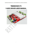
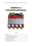
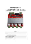
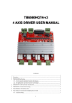
SensMax Hardware User manual Contents SensMax SE Uni-directional sensor ........................................................................................... 3 SensMax S1 Uni-directional sensor ........................................................................................... 3 SensMax PRO D2 Bi-directional ................................................................................................. 7 SensMax PRO D3 Bi-directional ................................................................................................. 7 SensMax SE Mobile Data collector .......................................................................................... 11 SensMax Pro PC Data collector ............................................................................................... 15 SensMax Pro TCPIP Data collector .......................................................................................... 18 SensMax Pro GPRS Data collector ........................................................................................... 22 SensMax Server ....................................................................................................................... 28 2 SensMax SE Uni-directional sensor SensMax S1 Uni-directional sensor User manual 3 Description of sensors: SensMax SE Uni-directional / SensMax S1 Uni-directional The sensor is designed to count visitors to the premises, that have one or more passages. Structurally, the sensor is designed as two units - transmitter and receiver. Devices are installed opposite each other, and form the infra-red barrier. The intersection of the barrier is fixed and stored in internal memory. The sensor SensMax S1 Uni-directional has an internal memory for 25 days, to store data for each hour. The sensor SensMax SE Uni-directional has an internal memory for 250 days, to store data for each hour. The sensor can not distinguish the direction of the passage, it considers each intersection. In the viewer statistics data from these sensors can be divided in 2, if necessary. Data from SensMax S1 Uni-directional is transmitted over the radio channel from the sensor to the collector. Distance communication is 20-50 meters, depending on the presence of walls and metal structures in the way of radio signals. Data from SensMax SE Uni-directional is transmitted via an infra-red link, using a special data collector. SensMax S1 Uni-directional Works with the following types of the collectors: SensMax PRO PC data collector SensMax TCPIP data collector SensMax GPRS data collector SensMax SE Uni-directional Works with collector type SensMax SE Mobile Data collector The sensors operate on AA type batteries. The operation time is more than two years, when providing data every hour. Attaching sensors to the data collector Each sensor must be attached to its collector. Following steps must be performed to attach sensors to the collector: 1. Insert the batteries in the sensor 2. Connect the collector to the power supply 3. Press the button on the collector 4. Press the button located inside the sensor enclosure For a more detailed description of the collector see the user's manual for the particular collector type. Sensor starts counting as soon as the current time and date are set. The time and date are set automatically when connecting to the collector for the first time. Sensors can be distinguished by the serial number. The serial number of SensMax S1 Uni-directional starts with "03". For example: 030000123 The serial number of SensMax SE Uni-directional starts with "01". For example: 010000123 4 Item description 1 4 3 5 2 6 Icon 1. 2. 3. 4. 5. 6. 7. Link lamp Crossing lamp RF Link lamp Power lamp Low Battery lamp Serial number Sound signal Status Flashes Flashes Flashes Flashes Flashes n/a Sound Description The sensors see each other Indication of the intersection Data transmission over the radio / Power supply The power indicator Low battery power The unique serial number The sensor is blocked Technical Specification Parameter Operating principle Determination of the direction Width of the passage Internal memory Carcass Power supply Data collection Dimensions Fixing to the wall Counting accuracy 5 Description Intersection of the IR beam Unidirectional Optimal 1m-6m, Max 8m 25 days, for each hour ABS Plastic, black 2AA + 3 AA batteries, up to 2 years lifetime Automatic for S1 Uni-directional Manual for SE Uni-directional 67x67x25 mm Two-sided adhesive tape 95% 3m, >3m +0.6%/m Installation Parameter Recommended distance from the floor Orientation Passage width Angle of the infrared radiation Fastening Installation examples 6 Description 1.5m-1.6m Horizontal Optimal 1m-6m, Max 8m 6% Two-sided adhesive tape SensMax PRO D2 Bi-directional sensor with an external power supply SensMax PRO D3 Bi-directional battery-powered sensor User manual 7 Description of sensors: SensMax PRO D2 Bi-directional / SensMax PRO D3 Bi-directional The sensor is designed to count visitors to the premises that have one or more passages. With the sensor it is possible to count the number of visitors and to determine the number of people in the real time, who are in the premises at the particular moment. Structurally, the sensor is designed as two units - transmitter and receiver. Devices are installed opposite each other, and form the infra-red barrier. The intersection of the barrier is fixed and stored in internal memory. The sensor has an internal memory for 25 days, to store data for each hour. The sensor has a built-in clock and calendar. The sensor distinguishes the direction of the passage. The direction entrance or exit is being set in the programme to view the statistics. Data is transmitted over the radio channel from the sensor to the collector. Distance communication is 20-50 meters, depending on the presence of walls and metal structures in the way of radio signals. Power supply of SensMax PRO D2 is from internal adapter. The installation of power wire has to be performed. SensMax PRO D3 sensor operates on AA type batteries. The operation time is more than two years, when providing data every hour. Sensors are designed to be used with the following types of collectors: SensMax PRO PC data collector SensMax TCPIP data collector SensMax GPRS data collector Attaching sensors to the data collector Each sensor must be attached to its collector. Following steps must be performed to attach sensors to the collector: 1. Connect the sensor to the power supply/ Insert the batteries in the sensor 2. Connect the collector to the power supply/ USB 3. Press the button on the collector 4. Press the button located inside the sensor enclosure For a more detailed description of the collector see the user's manual for the particular collector type. Sensor starts counting as soon as the current time and date are set. The time and date are set automatically when connecting to the collector for the first time. The bi-directional sensor may be distinguished from other SensMax sensors by the serial number. The serial number for this type of sensors starts with "04". For example: 040000123 8 Item description 1 3 4 2 5 Icon Status 1. 2. 3. Link lamp Crossing lamp Status lamp Flashes Flashes Flashes 4. 5. 6. Power lamp Serial number Sound signal Flashes n/a Sound Description Sensors see each other Indication of intersection DirA or DirB Data transmission over the radio, power supply Power indicator Unique serial number Sensor is blocked Technical specification Parameter Operating principle Determination of the direction Width of the passage Internal memory Carcass Power supply Data collection Dimensions Fixing to the wall Counting accuracy 9 Description Intersection of the IR beam Bi-directional Optimal 1m-6m, Max 7m 25 days, each hour for each passage direction ABS Plastic, black Power supply 12 VDC or 2AA + 2 AA batteries, >1 year lifetime Automatic 67x67x25 mm Two-sided adhesive tape or screws 95% 3m, >3m +0.6%/m Installation Параметр Recommended distance from the floor Orientation Passage width Installation examples 10 Описание 1.5m-1.6m Horizontal Optimal 1m-6m, Max 7m SensMax SE Mobile Data collector User manual 11 Description of SensMax SE Mobile data collector Data collector SensMax SE Mobile is designed to collect the accumulated statistics of visits from the SensMax S1 Uni-directional sensors. This is a mobile data collector, which does not require a permanent connection to the computer. Data transmission from the sensor to the collector is done by the infra-red channel. To read data from the sensor, you must send it to the collector, and click the button. The collector may service 100 different sensors simultaneously. Data from all read sensors will be stored in internal memory, awaiting transfer of the statistics to the computer. Data transfer to PC The collector is connected via USB cable to the computer. Click the button “Download from collector” in SensMax EasyReport programme. Infra Red 1 m max USB For more information about using SensMax EasyReport program, refer to instructions for using the program. The collector has a built-in Li-Ion battery. It is automatically charging from the USB port. 12 Description of the elements of SensMax SE data collector. 1 2 3 4 5 6 7 Icon 1. 2. 3. 4. Read button Read lamp OK lamp Error lamp 5. 6. 7. Battery lamp Charge lamp USB port Status Short push Flashes Lights for 1 second Flashes 1 time Flashes 2 times Flashes 3 times Flashes 4 times Lights for 1 second Flashes on n/a Description Reading data from the sensor Reading is in process Reading is finished Sensor not found Reading error Collector memory is full Time is not set in the sensor Low battery charge Charging is in process USB port Collector technical specification Collector SE Mobile Data collection Working distance SensMax SE support Memory Carcass Power supply Dimensions PC connection Data transfer to PC 13 Manually, IR-channel Up to 1 meter from sensor Up to 100 sensors 2000 days АВS Plastic, black Li-Ion 600mA accumulator. Work on a single charge - 60 days (depends from capacity) 110x25x25 mm USB port Manually Setting time in data collector and sensor Both collector and every sensor has its own clock and calendar. The sensor is based on the clock to record visitor statistics in memory. Each entry in the memory contains information about date and time, so it is very important to check if the sensor’s clock is installed correctly. Time synchronization in the SensMax system is organized as follows: The collector receives the exact time from the computer at the time of each interaction with the SensMax EasyReport program. In turn, the collector transmits the exact time of the sensor, each reading the data. To set the time in the collector, follow these steps: Run the SensMax EasyReport program Connect the collector to the computer using a USB cable After these steps, your computer system time will be installed in the collector. To set the time in the sensor, just read the data from it with the collector. If the time is correct, a green OK indicate of will light on the collector, if the time in the sensor is not set, then the red Error indicator will flash 4 times. Failure to set time in the sensor can be only for one reason - the collector also has incorrect time set. Set the time in the collector, as described above and then re-download the data from the sensor. 14 SensMax Pro PC Data collector User manual 15 Description of SensMax Pro PC data collector Data collector SensMax SE Mobile is designed to read the data from SensMax sensors. The data collection is performed, using radio channel. The data from the collector is sent to the computer via USB cable. SensMax Agent is a programme that provides service to the data collector. The programme is designed to read the statistics from the collector and to transfer the data further, to the local directory or on the FTP server. All the SensMax Agent functions are described in the instructions for using this program. Attaching sensors to the data collector Each sensor must be attached to its collector. Following steps must be performed to attach sensors to the collector: 1. Connect the sensor to the power supply/ Insert the batteries in the sensor 2. Connect the collector to the power supply/ USB 3. Press the button on the collector 4. Press the button located inside the sensor enclosure Note: Button to search for new sensors is located on the frontal side of the collector, near the port USB. Button is pressed with a sharp object, such as a pencil or pen. A short press takes the collector in the search mode for the new sensor. Long press of the button (10 seconds) removes all the attached sensors from memory. One collector can service 10 SensMax sensors The collector has an internal memory for storing statistics for 250 days, as well as clock and calendar. The figure below illustrates an example of a collector. Radio channel up to 50 m Radio channel up to 50 m FTP, Dropbox... Shop 2 Shop 1 Head office 16 Shop manager Description of SensMax Pro PC elements 1 2 3 4 Icon 1. 2. 3. 4. PC Link RF Link Error USB Port Status Flashes Flashes Flashes n/a Technical specifications of the collector Pro PC Collector Data collection Working distance Number of sensors serviced Memory Carcass Radio channel frequency Radiant power Power supply Dimensions PC connection Transfer of data to the PC 17 Automatic, radio channel 20-50 meters 10 250 days АВS Plastic, black 2,4 GHz 3.2 mW Computer USB port 110x25x25 mm USB port Automatic Description Data exchange with PC Reading data from the sensor Sensor reading error USB port SensMax Pro TCPIP Data collector User manual 18 Description of SensMax Pro TCPIP data collector Data collector SensMax SE Mobile is designed to read the data from SensMax sensors. The data collection is performed, using radio channel. The data from the collector is sent to the computer via TCP/IP protocol. SensMax Server is a programme, that provides service to the data collector. The programme is designed to read the statistics from the collector. The description of the programme is provided below. Attaching sensors to the data collector Each sensor must be attached to its collector. Following steps must be performed to attach sensors to the collector: 1. Connect the sensor to the power supply/ Insert the batteries in the sensor 2. Connect the collector to the power supply/ USB 3. Press the button on the collector 4. Press the button located inside the sensor enclosure Note: Button to search for new sensors is located on the frontal side of the collector, near the port USB. Button is pressed with a sharp object, such as a pencil or pen. A short press takes the collector in the search mode for the new sensor. Long press of the button (10 seconds) removes all the attached sensors from memory. One collector can service 10 SensMax sensors The collector has an internal memory for storing statistics for 250 days, as well as clock and calendar. The figure below illustrates an example of a collector. Radio channel RJ-45 FTP SensMax Protocol Statistics screening Computer with installed SensMax Server 19 Description of SensMax Pro TCPIP controller elements 5 1 6 2 3 7 4 Icon 1. Status Status Lights 2. Radio Link Flashes Lights 3. Clock Sync Flashes Lights 4. 5. 6. 7. Server Link USB port Button RJ-45 connector Lights n/a n/a n/a Description The collector is trying to connect to server Collector is functioning Technical specifications of the collector Collector TCP/IP Data collection Collector-sensor distance Number of sensors serviced Memory Carcass Radio channel frequency Radiant power Power supply Dimensions PC connection Transfer of data to the network 20 Automatic, radio channel 20-50 meters 10 250 days АВS Plastic, black 2,4 GHz 3.2 mW Internal power supply 5V 110x66x28 mm USB port Automatic The connection with sensor exists Search for new sensor Clock/calendar successfully synchronised with server The connection with server exists USB port Button for pairing with sensors Socket for internet connection Configuration of the collector SensMax Pro TCPIP When first used, the collector must be configured. SensMax USB Config is a program to configure the collector. Connect the collector to the computer via USB cable. Run the SensMax USB Config program. Click the button . Server Settings IP Address -IP server address ( the address of the computer where the server is installed) Port -Server port (default 2020) TCP/IP Settings IP Address Network Mask Gateway - the address of this collector (if DHCP not used) - the network mask (if DHCP not used) - the gateway (if DHCP not used) Please enter your settings and click "Save Setting ". Note: Windows Firewall may be blocking the port 2020. Make sure that this port is added to the exceptions on the computer, on which SensMax Server installed. 21 SensMax Pro GPRS Data collector User manual 22 Description of SensMax Pro GPRS data collector Data collector SensMax Pro GPRS is designed to read the data from SensMax sensors. The data collection is performed, using radio channel. The data from the collector is sent to the computer via GPRS protocol. SensMax Server is a programme, that provides service to the data collector. The programme is designed to read the statistics from the collector. The description of the programme is provided below. Attaching sensors to the data collector Each sensor must be attached to its collector. Following steps must be performed to attach sensors to the collector: 1. Connect the sensor to the power supply/ Insert the batteries in the sensor 2. Connect the collector to the USB 3. Press the button on the collector 4. Press the button located inside the sensor enclosure Note: Button to search for new sensors is located on the frontal side of the collector, near the port USB. Button is pressed with a sharp object, such as a pencil or pen. A short press takes the collector in the search mode for the new sensor. Long press of the button (10 seconds) removes all the attached sensors from memory. One collector can service 10 SensMax sensors The collector has an internal memory for storing statistics for 250 days, as well as clock and calendar. The figure below illustrates an example of a SensMax Pro GPRS collector use: Radio channel FTP SensMax Protocol Statistics browse Computer with installed SensMax Server 23 Description of SensMax Pro GPRS collector’s elements 7 3 2 1 6 5 4 Icon Status 1. GSM NET Flashes GSM/GPRS network is found 2. Sensor Link Lights The connection with sensor exists Flashes 24 Description Search for new sensor 3. Clock Sync Lights Clock/calendar successfully synchronized with server 4. Server Link Lights The connection with server exists Flashes No connection to the server 5. USB port n/a USB port 6. Button n/a Button for pairing with sensors 7. SIM Connector n/a Socket for SIM card connection Technical specifications of the collector Collector TCP/IP Data collection Collector-sensor distance Number of sensors serviced Memory Carcass Radio channel frequency Radiant power Power supply Automatic, radio channel 20-50 meters 10 250 days АВS Plastic, black 2,4 GHz 3.2 mW Internal power supply 5V Dimensions 110x75x25 мм PC connection USB port Transfer of data to the network Automatic GSM standards supported 850 MHz / 900 MHz / 1800 MHz / 1900 MHz The volume of consumed traffic in GPRS network The collector consumes a small amount of Internet traffic for work - about 0.4 kB per one session of data transfer to the server. The volume of traffic depends from the frequency of the data transfer to the server. The amount of data per day is calculated as follows: G=A/B*C Where G is the volume of traffic in kB, A is a number of minutes in a day (1440), B is a frequency of updates, C is a consumption of traffic by the collector. For example, the frequency of data updating is set for 20 minutes in settings. During 24 hours of work the collector will spend: 1440 / 20 * 0.4 = 28,8 kB (per daynight) 28,8 * 31 = 892,8 kB (per month) 25 SIM card connection Collector supports standard SIM cards, 15 х 25 mm. Attention Collector does not support PIN code call. PIN code call must be disabled before use. 26 Configuration of the collector SensMax Pro GPRS When first used, the collector must be configured. SensMax USB Config is a program to configure the collector. Connect the collector to the computer via USB cable. Run the SensMax USB Config program. Click the button . Server Settings IP Address installed) Port -IP server address ( the address of the computer where the server is -Server port (default 2020) GPRS Settings Access Point Name Username Password Please enter your settings and click "Save Setting ". Note: Windows Firewall may be blocking the port 2020. Make sure that this port is added to the exceptions on the computer, on which SensMax Server installed. 27 SensMax Server User manual 28 SensMax Server software is designed to read the statistics from the collectors SensMax TCPIP и GPRS and to manage settings of these collectors. Settings made in the programme, automatically applied to all connected collectors. Installation Install SensMax Server software on any computer. After installation, run the server configuration: Note: In Windows 7 the program must be run by administrator. Settings TCP Listen Address Listening IP address. If the computer receives an address on DHCP, you must enter 0.0.0.0 Port Listening port. Default 2020. Windows Firewall Settings: Make sure that on a computer that is running SensMax Server, port 2020 is added to exceptions. At Windows 7, you need to add gprsserver.exe programme, which is located in a directory C:\Program Files\SensMax\Server, to exceptions Data Directory Selecting a directory to store the statistics from the sensors. This directory should be allowed the right read \ write. Current power profile To optimize the use of batteries in the sensors it is necessary to configure the system. The user if offered to chose one of four power profiles: Test Mode – is used in the test mode 29 Normal Mode – recommended power profile Max battery live – rare polling of sensors, which allows maximally prolongation of battery live. Custom - manual entering of settings RF Sync Period Poll interval of sensors, in seconds. It is recommended to set the value of 1800 (30 minutes) to save batteries in the sensor. Sound Alarm Period This setting is designed for the sensor. The sensor will signal an error if it will be blocked longer than this interval. Recommended value of 900 (15 minutes). Upload Interval This setting is designed for the collector. Determines the range of data discharge to the server. Clock Auto Sync Automatic time synchronization of the collector and the server. It is recommended to check this box. Sensor Auto Erase Automatic sensor memory cleaning after reading. It is recommended to check this box in order to save sensor’s batteries. Beep When Crossing If this check-box is set, the sensors will make a sound at each new visit. Use collector buffer for data backup If this check-box is set, the collector will store the data for the last 250 days in internal memory. If the tick is removed, the data from the collector will be cleared after a successful transfer to the server. Close data files If the tick is set the server will close the data files after the communication session with collector is ended. This mode loads the server computer stronger, but this mode is necessary for the use of FTP server for the later data transfer. If the tick is removed, server will hold data files open, this reduces the system booting. Please, enter settings and press the “Save” button to start the server. If all is done correctly, the server will start: The names of the of sensors Each sensor can be given its own name. For the naming the sensors use Sensors tab. A list of sensors contained in the database will appear: 30 To give a name to a sensor, you need to double-click in the Name box, in front of the sensor of interest, and enter a name. Note: If the list is empty, this means, that none of the sensors is in the database yet. 31