1
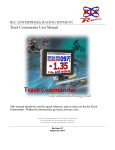
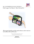
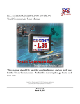
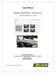
RLC ENTERPRISES, RACING DIVISION
Chase Commander User Manual
This manual should be used for quick reference and on track use
for the Chase Commander.
Copyright Notice. All materials copyright © 2010, R.L.C. Enterprises, Inc., all rights reserved.
Micro Pod and the Micro Pod Logo are Trademarks of R.L.C. Enterprises, Inc.
R.L.C. Enterprises Reserves the Right to Change Specifications without Notice.
Revision 2.3
April 27, 2010
Icon showing locked
onto a differential
Icon showing which
GPS unit is connected
(5 or 10 Hz)
Icon showing
you are logging
Icon showing that
a camera is
Timing
Number of satellites
unit is locked onto
Current running
lap time
Speed
Fastest lap time
Currently
showing
predictive lap
time. (Red
means you are
faster than your
fastest lap time,
green means
slower). This is
also where your
completed lap
ti
ld
Time
Built in 3-Axis GForce Sensors
Lap
Session time (how long
you have been logging
USB Host
(Easy File Transfer)
High Accuracy GPS with
WAAS Technology
5 or 10Hz
USB Client
for Easy Updates
12V Cigarette Lighter Adapter
(Simple Plug-in Power)
Synchronized Video
(Data Embedded in Video)
Table of Contents
CHAPTER 1- INTRODUCTION
CHAPTER 6 – SYNCHRONIZED VIDEO
Installation
ChaseCam PDR Camera
Booting Up
Connecting to the ChaseCam PDR
Getting Around
Verify Connection
Indicator Field
Verify ChaseCam PDR Recording
Lap Times, Predictive and Split Times
Removing Power
Session Timer/Lap Counter
Downloading Synchronized Video Log File
Corrupt Synchronized Video File?
CHAPTER 2 – USER PREFERENCES
Timing Screen
CHAPTER 7 – UPDATING THE CHASE
Display Screen
COMMANDER
Files Screen
Logging Screen
Systems Screen
Beacons Screen
CHAPTER 3 – GPS
Setting the Start/Finish Line
Creating a GPS Track Map
Exact Track Map
GPS Lap Timer
GPS Predictive Lap Timer
GPS Split Lap Timer
GPS Autocross Timer
GPS Performance Mode
GPS Connection Time
CHAPTER 4 – RACE LOG FILES
Uploading Race Log Files
Copying Backup Log Files
CHAPTER 5 – STOP LOGGING /
SUMMARY SCREEN
Stop Logging
Summary Screen
Ch.1
Introduction
First and foremost, thank you for buying our products. You are a valued customer and R.L.C. looks forward to a
mutually beneficial relationship with you. In order to help insure your success, we have prepared this getting
started guide for you. Use this step-by-step Getting Started Guide/User Manual to get started for the first time
and as a reference during the normal operation of your Chase Commander. The Chase Commanders have a
touch screen for navigation. Simply tap on the screen to make your selection or to get to another screen. We will
cover how to get around the unit using only the touch screen in the section below.
Installation
Attach the Chase Commander unit to the suction cup mount by snapping it in, RLC Racing logo should be on the
top. Now with the unit attached to the suction cup mount, mount the unit to the windshield in a desirable place.
You will want to mount it close enough so you can touch the screen easily when your seat belts are tight, you will
need to do this when you set a start/finish line. Connect the GPS unit to the serial port marked GPS on the
harness. You will want to mount the antenna for the GPS unit on the outside of the car so it is in clear view of
the sky. The antenna is magnetized so it is easy to mount almost anywhere. For customers using the 10 Hz GPS
unit, we have included a piece of Velcro so you can securely mount your GPS unit anywhere in your car. The 5
Hz GPS is an all-in-one unit and is magnetized so that it mounts to the outside of the car easily, no Velcro is
required. We recommend that you place the GPS antenna somewhere on the center line of your car (away from
the engine compartment) in clear view of the sky.
Booting Up
To power the Chase Commander, plug it into the cigarette lighter. The GPS is powered through the harness of
the Chase Commander. Depending on your car you may need to turn the car on. Once you have powered the
unit, you should see a startup screen (Fig 1). This screen will display while the system is loading for a few seconds
and then you will see the driving screen (Fig 2). The driving screen is the screen which you will use during races.
The GPS will take about a minute to connect and the screen will change to Figure 3. This screen will be referred
to as the Driving screen. You will set the start/finish later.
Figure 1 – Startup Screen
Figure 2 – Driving Screen
1
Figure 3 – Driving Screen Ready
Ch.1
Getting Around
Navigating through the different screens of the
Chase Commander is easy; simply use the touch
screen. To navigate to the different screens, touch
the screen and buttons will pop up from the bottom
and top of the screen. To select user preferences
touch the Main Menu button, to review a summary
of your last session touch the Summary button, to
change to performance mode touch the
Performance button, and to change to drifting mode
touch the Drifting button (must have Dual GPS for
this option) (Fig 4).
Figure 4 – Navigation Buttons
Indicator Field
The indicator field is a useful tool for drivers to know whether you are connected to satellites, logging, or if a
camera is attached. There will be a ‘5’ or a ‘10’ in the indicator field to indicate which GPS unit you have
connected to your unit. In the upper right hand corner there is a GPS satellite bar that lets you know how many
satellites you are connected to and it will blink on and off when it is connecting to satellites. The ‘L’ stands for
logging and it will turn on when the Chase Commander has started logging data and will turn off when it stops
logging. The camera icon will turn of if a ChaseCam camera system connected to the Chase Commander. The
‘D’ stands for differential satellite mode.
Indicator Field
GPS Satellite
Indicator
Figure 5 –Indicator Field
Lap, Predictive, and Split Times
Lap times are displayed during the race and require no user intervention. Please see the GPS chapter on how to
set up the lap timers. Lap times, predictive and split times are flashed on screen and remain on screen for a set
amount of time (Fig 6, 7, and 8). Below the lap time is a value that tells you if you were faster or slower than your
fastest lap time. The predictive lap time displays the time difference between your fastest lap time and your
current lap time at that particular spot on the track. The split lap time displays your time between the markers you
set on the track and the time difference between your best time and your current time.
2
Ch.1
Figure 6 – Lap Timer
Figure 7 – Predictive Lap Timer
Figure 8 – Split Lap Timer
Session Timer / Lap Counter
The session time and lap counter are displayed on the bottom of the driving screen (Fig 9). The lap counter keeps
track of number of completed laps you have made; it will increase every time you cross the start/finish line and
complete a lap. Please see the setting the start/finish line section below on how to set the start/finish line. The
session time is denoted by the ‘S’ and displays how long you have been on the track and you can figure out how
long until the end of a timed race. The session time automatically starts when you reach logging speed.
Session Time
Lap Number
Figure 9 – Lap Counter and Session Time
3
Ch.2
that you can section up the track and only work on
that particular section of track. Predictive timing
does not work while the unit is in autocross mode.
Track Mapping mode is explained later in this
manual. This is also where you can reset your fastest
lap and the start/finish line. The fastest lap is used
in both the predictive and classic lap timing mode.
This is the lap that all times are compared to and is
displayed in the Driving screen. If you reset the fast
lap you will have to drive a complete lap around the
track before the predictive timing will work, you do
not have to reset a start/finish line. The Delete All
Data button will delete the start/finish line and the
fast lap. You will have to reset a start/finish line and
drive a complete lap before predictive lap timing will
work. Press either the Exit button if you are done
setting your preferences or select another option in
the Main Menu screen. When the Exit button is
pressed, your preferences are saved and you are
taken back to the Driving screen.
User Preferences
To set user preferences you need to be in the Main
Menu screen. To set your preferences, touch the
screen anywhere but on the Set Start/Finish button.
Two buttons will appear at the bottom right of the
screen. If you accidentally hit the Set Start/Finish,
don’t worry you can reset it in the Main Menu
screen. Press the Main Menu button and the Main
Menu screen will appear. From here you will set
your preferences.
Timing Screen
The Chase Commander has 5 different timing
modes that you can choose from; it ships from the
factory in predictive mode. Touch on the Timing
button on the right to set the timing mode on the
left (Fig 10).
Display Screen
The Display screen (Fig 11) allows you to set up the
screen the way you want. You can select the screen
color, brightness or calibrate the screen.
Figure 10 – Timing Screen
The Timing screen allows you to select which timing
mode you want the Chase Commander unit to be in.
Predictive Timing puts the unit in predictive mode;
you will need to set at start/finish and drive a
complete lap around the track before you will receive
predictive lap times. Classic Lap Timing mode will
only give you your lap times as you cross the
start/finish line. Autocross mode allows you to set a
finish line, while the start line is based off G-Forces.
Split Timing lets you set a different start/finish so
Figure 11 – Display Screen
There are six different backgrounds to choose from,
three plain colors and three graphical backgrounds.
The Foreground option allows you to either fill or
outline the numbers on the screen. Choose
whichever one allows you to see the numbers the
best. LCD Brightness allows you to choose between
day and night mode. Day mode is brighter than
4
Ch.1
night mode. The Touchscreen option allows you to
calibrate the touchscreen. The touchscreen is already
calibrated in the factory but you can choose to redo
it if you don’t feel the screen is responding well to
your touch. If you calibrate the touchscreen you
need to power the unit off and on before the
changes will take effect. Press either the Exit button
if you are done setting your preferences or select
another option in the Main Menu screen. When the
Exit button is pressed, your preferences are saved
and you are taken back to the Driving screen.
how you want your Chase Commander to start and
stop logging.
Files Screen
Figure 13 – Logging Screen
Logging Speed is the speed which you want to reach
before your unit starts to log data. You don’t want
to set it too low so you won’t start logging while you
are driving around the pits. We recommend 35
mph. Stop Logging is where you set how long after
the car has stopped that you want to stop logging.
The Logging screen is also where you set the
Logging G-Force limit. This setting is used in both
the Performance Mode and Autocross Mode. You
want to set it low enough so that your car will start
logging when it accelerates but not so low that it
starts logging when your car barely moves forward.
We recommend starting at 0.2 g. Press either the
Exit button if you are done setting your preferences
or select another option in the Main Menu screen.
When the Exit button is pressed, your preferences
are saved and you are taken back to the Driving
screen.
The Files screen (Fig 12) is where you can see how
many logged session files or backup files you have
on your unit.
Figure 12 – Files Screen
File Storage shows you how much of the memory
you have used and how many minutes you have left
to log. The Log Files shows you how many files you
have logged, the size of the files, and whether or not
you have a USB memory stick plugged into the unit
to download files. Press either the Exit button if you
are done setting your preferences or select another
option in the Main Menu screen. When the Exit
button is pressed, your preferences are saved and
you are taken back to the Driving screen.
System Screen
The System screen (Fig 14) allows you to set the
time and date so the logged files will have the correct
times. This screen also lets you “zero out” your
internal 3-axis G-Force sensor.
Logging Screen
The Logging screen (Fig 13) is where you set your
logging preferences. This is where you will set up
5
Ch.2
preferences or select another option in the Main
Menu screen. When the Exit button is pressed, your
preferences are saved and you are taken back to the
Driving screen.
Figure 14 – System Screen
Once you mount the Chase Commander in your car
as level as you can, press the tare button to “zero
out” the G-Forces. You can select between standard
or metric units. Press either the Exit button if you
are done setting your preferences or select another
option in the Main Menu screen. When the Exit
button is pressed, your preferences are saved and
you are taken back to the Driving screen.
Beacons Screen
The Beacon screen (Fig 15) allows you to set the
number of beacons for Predictive lap timing mode.
Figure 15 – Beacons Screen
You can set up to 99 beacons. For a 1 mile track we
would recommend 10 beacons, for a 2 mile track we
would recommend 15 beacons, for a 3 mile track we
would recommend 20 beacons, etc. These should
be considered starting points, please adjust the
number of beacons to you your liking. Press either
the Exit button if you are done setting your
6
Ch.3
GPS
GPS is included with all Chase Commanders, and allow you to get exact track maps, lap times, predictive times,
and split times. Standard GPS units included with your Chase Commander are the 5 Hz, although a 10 Hz model
is also available from R.L.C. We recommend that you place the GPS antenna somewhere on the center line of
your car (away from the engine compartment or any type of electrical noise), in clear view of the sky, and
horizontal or parallel to the sky.
When connecting the GPS for the first time it could take upwards of an hour to lock onto satellites and start
transmitting data, due to a significant change of position. When making a connection for the first time make sure
the antenna is in clear view of the sky and the cord is completely uncoiled. After the GPS has established a
connection for the first time, connecting to satellites can take as little as 5 seconds to a maximum of 1 minute.
The top right of the screen will flash until a GPS connection has been made. To view how many satellites your
GPS unit is connected to, look at the satellite bar on the top right of the screen. When the GPS initially connects,
it will only be connected to maybe 4 satellites. As the GPS units stays on it will connect to more satellites
automatically. When a differential signal has been locked onto a ‘D’ with a box around it will appear in the upper
left hand corner. Also indicated in the upper left hand corner of the screen will be the GPS (5 or 10 Hz), a ‘L’ will
appear when you are logging data, and if you have a Chase CAM camera connected a camera icon will appear.
If you would like to verify that the GPS is working and connected properly, you can simply look at the top right
hand corner of the screen at the GPS satellite indicator (Fig 16). The GPS satellite indicator has bars, each bar
represents a satellite the Chase Commander is connected to.
GPS Satellite
Indicator
Figure 16 – GPS Verification
Setting the Start/Finish Line
A start/finish line must be set on your unit so the pop up lap timer, lap counter, and predictive lap timer works
properly. You must be moving forward and on the track (not in the hot pits) when you set the start/finish.
Usually you set the start/finish line on your first lap around the track. Once the start/finish line has been set, your
unit will remember it until you drive a different track and/or set a different start/finish line. This start/finish lap
will also be recorded as your base lap for when the unit is in predictive mode. To read more about predictive lap
timing, see the GPS predictive lap timer section below.
7
Ch.3
To set the start/finish line you need to press the big, green Set Start/Finish button on the driving screen (Fig 3).
When your car passes the spot on the track that you want to mark as the start/finish line press the Set Start/Finish
button. Make sure you drive a complete lap around the track so that your base lap for predictive lap timing will be
established.
Creating a GPS Track Map
GPS is the most accurate & precise way to map a track. Every lap that you take around the track is distinctive and
unique. Unlike mapping a track with G-Force, just a single lap will render an accurate map based on your exact
line you drove. G-Force requires that you make multiple laps and then the PC software will average your laps and
create a track map based on those averages. Each lap will look exactly the same and the data can be off as much
as 30 ft! With RLC, each lap will look different because each line you drive around the track is slightly different.
The data that is recorded from each lap is accurate to within inches. R.L.C. does not average and compress your
data to create a track map; instead our software creates a track map based on each individual lap. The Race
Analyzer software creates a track map based on how much of the track you drove on (Fig 17). The left side of the
track will be the leftmost line your car drove on the track and the right side will be the rightmost line your car
drove. The narrower the track means that you drove close to the same line every time you drove that part of the
track. Now when you analyze your data on the Race Analyzer software, each lap will appear within the track that
was created by your car. The track map that was created is specific to the data for that particular session. Each
session will render a different track map because your drive differently every time.
Figure 17 – Track Map
Exact Track Mapping
R.L.C. offers Exact Track mapping which is the most precise way to map a track. Exact Track allows you to see
your lines within the width of the actual track. We do this by driving the right and left sides of the track so that
you are able to get the exact widths everywhere along the track (Fig 18). When you load your log files in our Race
Analyzer software, your laps are shown within the width of the track. You can see the exact lines you drove
everywhere on the track and you are able to find the fastest line. You only have to create a track once and you
8
Ch.3
have the track forever. You can even check at R.L.C.’s website to see if the Exact Track map has already been
made and download it.
Figure 18 – Exact Track Map
Figure 19 – Exact Track Map, Close Up
To create an Exact Track map make sure that you have a differential GPS lock. You can check to see if you
have a differential lock looking at the indicator field in the top left hand corner of the screen and looking for the
‘D’ to be on. If you see the ‘D’ you are locked in, if not give it some more time. A differential lock will ensure
that you get the most accurate track map. Before you go out onto the track, like while in the hot pits, press
anywhere on the screen to bring up the navigation buttons. Touch the Main Menu button, touch the Timing
button, touch the Track Mapping button, the touch the Exit button (Fig 20). A track mapping screen will appear
prompting you to press ‘Start’ (Fig 21). Once you are in the track mapping screen, drive out onto the track and
place your tires as close to the edge of the track as you can (you choose which side you want to drive first). When
you are ready, press the ‘Start’ button; a screen will appear that displays the distance traveled and the distance to
the start (Fig 22). Drive the left side of the track. Drive past your initial staring point and then cross over to the
right side of the track. Again place your tires as close to the edge of the track as possible and drive the right side of
the track. Drive past your initial starting point and press the ‘Stop & Save’ button and the Exact Track Map is
saved. The car must travel in the same direction for each lap. If for any reason you want to abort the track
mapping press the ‘Cancel’ button.
Figure 20 - GPS Track Mapping Screen
Figure 21 - GPS Track Mapping Screen
9
Figure 22 - GPS Track Mapping Screen
Ch.3
You want to drive around the track as slow as you can. If you have the 5 Hz GPS you want to stay around 20-25
mph (32-40 kph) and with the 10 Hz GPS around 25-30 mph (40-48 kph). The slower that you drive the closer
together the GPS samples are, this creates a more accurate and smooth track map. The track map will be one of
the log files. Send the log file (.bin) to RLC Racing and they will create the Exact Track map so that you can use it
in the PC software. Make sure you include what track it is, the configuration (if there are alternates), website to the
track, and any additional information that may be helpful. RLC Racing will use this information and Google
Earth to add rumble strips, buildings, flag stations, bleachers, and any other track characteristics we can see. We
will send you the Exact Track map file (.map) and now you can analyze your data within the confines of the actual
widths of the track.
GPS Lap Timer
GPS is used to measure lap times instead of a
stationary beacon you have to place on the track.
GPS is more exact and it eliminates the need of
buying an expensive lap timer. The GPS lap timer is
automatically set up once you set the start/finish
line, which was covered in an above section. Now
your lap time will pop up on your unit every time
your car crosses the start/finish line (Fig 23). Also
displayed is the difference between you current lap
time and your fastest lap time. If your lap time is
faster then it will be (-) in red and if the lap time is
slower then it will be (+) in green.
Figure 23 – Lap Timer
GPS Predictive Lap Timer
Predictive lap timing is a great tool when you want to
try new things on the track and need some instant
feedback. When the race logger is in predictive
mode, it will inform you of the time difference at
that current location on the track between your
current lap and your fastest lap (ever), so you know if
things are helping or hurting (Fig 24). If you are
currently faster than your fastest lap then the time
difference will be (-) in red and if you are currently
slower then it will be in (+) green. The GPS
predictive lap timer is automatically set up once you
set the start/finish line, which was covered in an
above section.
Figure 24 – Predictive Lap Time
10
Ch.3
GPS Split Lap Timer
The split lap timing feature on the RLC race loggers lets you divide up the track to work on specific sections to get
your lap times down. By setting markers, you can section off the parts of the track you want to work on. You can
set to two split markers on the track. When the unit is in split mode it will display the time it took to get through
the same markers you set and the difference between your current time and your best time (Fig 25). If you were
faster than your fastest time then the time difference will be (-) in red and if you are currently slower then it will be
in (+) green.
Figure 25 – Split Lap Time
Figure 26 – Split Setup Screen
To set the split lap timer, navigate to the Timing screen (Fig 10). Touch the Split button then press the Exit
button. Another screen will appear (Fig 26) that will allow you to set a split beacon. Press the ‘Set’ button once
before and once after the section of track that you want to work on. Now every time you cross the marker the
time will start and it will stop when you cross the next marker. Your time will flash up on the screen along with
the time difference between your current run and your fastest run.
GPS Autocross Timer
The Autocross mode on the Chase Commander lets you start timing without having to set a start line. The Chase
Commander does not require a start line to be set because it starts logging/timing using the internal G-forces
(when your car accelerates it starts timing). G-Force limits can be set in the Logging screen (Fig 13). Your first
time through the course you will have to set a finish line. Every time you line up to take another turn you will
need to press on the screen where the time is to reset the unit. Once the unit has been reset to zero, the Chase
Commander is ready for another run.
To place the Chase Commander in Autocross mode, navigate to the main menu. Touch thee ‘Autocross Mode’
button in the Timing screen. When you exit from the main menu you will see a screen prompting you to set a
finish line (Fig 27). Press the Set New Finish Line button when you cross the finish line.
11
Ch.3
Figure 27 – Autocross Mode
Now when you accelerate the timer will start and it will stop when you cross the finish marker. Your time will
flash up on the screen along with the time difference between your current run and your fastest run. The fastest
time will reset every time your unit is powered off.
GPS Performance/Drag Mode
The Chase Commander can easily be switched over to Performance/Drag Mode. The Performance Mode allows
you to measure your car’s horsepower, acceleration (0-60 or 0-100 mph), deceleration (60-0 or 100-0 mph), ¼ and
1/8 mile times, and max G’s.
To place the Chase Commander in Performance mode touch on the screen, you will see two buttons drop down
from the top of the screen (Fig 28). Touch on the ‘Performance’ button and the Drag Mode screen will appear
(Fig 29).
Figure 28 – Navigation Buttons
12
Ch.3
Figure 29 – Performance Mode
Figure 30 – Performance Mode 2
Enter in the weight of your car and select which performance measurements you want to see. Simply touch on
the screen in the different areas to change the measurements. Above is another screen shot of more performance
measurements (Fig 30). These performance measurements can be selected on the fly (while the car is moving).
All performance measurements will start off of G-Forces which can be set in the logging screen (Fig 13). Once
you are done with your run you will need to click on the ‘Reset’ button to reset all measurements. For
deceleration measurements a ‘Ready’ indicator will appear in the bottom left hand corner when you have reached
the appropriate speed.
When you are done with performance measurements you can go back to the timing screens by touching on the
‘Go Back’ button when the car has come to a complete stop.
13
Ch.4
Stop Logging / Summary Screen
Stop Logging
When you are done with your track session and your
car has come to a stop, the Stop Logging button will
appear on the bottom of the screen (Fig 31). You
can either press it to stop logging or let the unit stop
logging on its own (you set the time in the Logging
screen). It is important for the unit to stop
logging before power is removed! If you remove
power before the unit has stopped logging then you
could lose lap information or your log file could
possibly become corrupted and you will not be able
to play it on the Race Analyzer Software. This is
why we recommend direct wiring to your battery.
The next time you power the unit on the fastest lap
from the previous session is displayed in the Driving
screen and the entire summary of the previous track
session can also be viewed in the Summary screen.
Figure 31 – Stop Logging Button
Summary Screen
When the unit has stopped logging, the Main
Menu/Summary button will appear at the bottom
right corner of the screen. Once you have stopped
logging, you can view the Summary Screen (Fig 32)
and see a summary of your track session. You can
sort your data by lap or by time by pressing LAP or
TIME. Press the up or down arrow buttons to
scroll up or down through your lap times. When
you are done you can either press the Timing button
to go back to the Driving screen or press the Main
Menu button to see the Main Menu screen.
Figure 32 – Summary Screen
14
Ch.5
Race Log Files
Each time you go out on the track the Chase Commander creates a logged file session. These logged sessions can
downloaded to your PC to analyze the data with the RLC Race Analysis software with the USB stick provided
with your unit. To transfer the logged session files from your Chase Commander to a PC you only need to
connect a USB memory stick, there are no extra cables to attach just the USB stick. Make sure the car is not
running before you upload, copy, or delete files from the Chase Commander. Each time you offload a log file it
makes a copy and stores it in a backup folder on the Chase Commander for future use.
Uploading Race Log Files
To transfer a logged session from the Chase Commander to a PC you will need the USB memory stick that was
included with your Chase Commander but also available at your local office store. Insert the USB memory stick
into the USB connector coming out the side of the unit. The Chase Commander will recognize the USB stick and
if there are log files to upload then it will switch over to the Files screen (Fig 33). The Files screen will show you
how many log files there are to upload. Touch the Transfer to USB button to upload the log files. With the
logged sessions now on your USB stick, you can load them into the RLC Race Analyzer software and study your
data. Every time you offload a log file from the Chase Commander it will automatically create a backup file. This
backup file is stored in a backup file directory on the Chase Commander for future use. Please see the section
below on how to copy and offload a backup file form the Chase Commander.
Figure 33 – USB Stick Plugged In
Copying Backup Log Files
To offload the backup files navigate to the Files screen. Simply plug in the USB stick that was provided with the
Chase Commander and touch the ‘Copy’ button under the File Storage section on the screen (Fig 33). Your
backup log files will start to copy onto your USB stick. With the logged sessions now on your USB stick, you can
load them into the RLC Race Analyzer software and study your data. You can also choose to delete the backup
files from your Chase Commander by clicking the ‘Delete’ button.
15
Ch.6
Synchronized Video
RLC worked closely with ChaseCam to produce the only truly synchronized video. By connecting a ChaseCam
PDR to a Chase Commander the data is actually embedded in the video file to create just one file. By embedding
the data in the video file we ensure that the data being taken by the Chase Commander (speed, track position, lap
times, etc.) is in fact directly linked to the video being taken by the camera. Now when you play your synchronized
video log file on the PC Race Analysis Software your video, data, and track position are exactly linked. You can
click any place on the track and your video and data will all jump to that exact position. Knowing that your data
and video are truly synchronized you can analyze your data in more depth than ever before. You can see the exact
position you applied the brakes, when you dove into a turn, and when got back on the throttle. Compare this to
your fastest lap and you will improve your lap times in no time at all.
If your firmware is an older version then you will
need to download the latest firmware from the
ChaseCam website,
www.chasecam.com/pdr.update, and install it.
ChaseCam PDR Camera
The ChaseCam PDR needs to have its own source
of power; again we recommend that you wire
directly to the battery, and needs to share the same
ground as the Chase Commander.
Settings on the ChaseCam PDR Camera
With up-to-date firmware installed on your unit you
can now load the pre-defined shortcut option that
allows the ChaseCam PDR to work exclusively with
the Chase Commander. To load this pre-defined
option press the Menu button on the ChaseCam
PDR, select the Shortcuts option, select the Data
Acquisition option, then select Data Acq 5 – Chase
RLC (Fig 35).
Firmware
The ChaseCam PDR needs to have the latest
firmware, version 01.02.12 or higher, installed so that
it will properly communicate with the Chase
Commander. If you ordered your ChaseCam
camera recently from RLC or directly from
ChaseCam it will already have the latest firmware
installed. If you ordered from a dealer or it is an
existing camera you may want to check the current
version on your camera. To check the version
number on your ChaseCam PDR, look at the screen
while the camera is booting (Fig 34).
Figure 35 – ChaseCam PDR Shortcut
The pre-defined shortcut option needs to be loaded
so that ChaseCam PDR is set up properly to work
with the Chase Commander. There are no settings
that need to be set on the Chase Commander.
Figure 34 – ChaseCam PDR Loading Screen
16
Ch.6
Connecting To The ChaseCam
PDR
Both the Chase Commander are set up for
synchronized video. There is a cable on the harness
that is labeled ‘Video’ that plugs directly into the
back of the ChaseCam PDR (Fig 36). When
plugging in cables, make sure the car is turned off
and there is no power to the ChaseCam PDR or
Chase Commander.
Figure 37 – GLC Indicator
Also look at the ChaseCam PDR. When it is ready
to start recording the light on the front will be solid
green (Fig 38).
Figure 36 – Chase Commander Connected to ChaseCam PDR
Figure 38 – ChaseCam PDR Light Green
With the Chase Commander plugged into the
ChaseCam PDR the RLC unit will completely
control the camera; it starts recording when the
Chase Commander starts logging and stops
recording when it stops logging. There are no
special settings that you need to do on the Chase
Commander, it will automatically connect and
control the ChaseCam camera.
Verify ChaseCam PDR Recording
When you have successfully verified that your
ChaseCam PDR is connected to your Chase
Commander you need to verify that it is recording
properly. The Chase Commander will completely
control the ChaseCam PDR; it will tell the camera to
start recording when the RLC unit starts logging and
tell it to stop recording when the RLC unit stops
logging. When the L appears in the indicator field in
the top left hand corner of the screen, the RLC unit
is logging data (Fig 37). Check the light on the front
of the ChaseCam PDR, it should be flashing red to
indicate that it is recording (Fig 39).
Verify Connection
When you successfully set the ChaseCam PDR up
and have connected it to the Chase Commander it is
time to verify the connection. Start your engine and
look at the screen of the Chase Commander. When
the Chase Commander recognizes that you are
connected to a ChaseCam camera you will see a
camera icon in the top left of the driving screen in
the indicator field (Fig 37).
17
Ch.6
Corrupt Synchronized Video
File?
If you find that your camera turned off accidentally
while out on the track or you removed power too
soon, your synchronized video file will be corrupt.
You cannot open it in the Race Analysis Software
but you can still view it as a standard video file.
Figure 39 – ChaseCam PDR Light Red
Removing Power
The log file on the Chase Commander can always be
used for data analysis, even if the synchronized video
file is corrupted. The data (.bin) log file on the
Chase Commander only contains the data, not the
video. Use the USB memory stick included with the
Chase Commander to offload the log file.
When you have finished your session and are ready
to turn your engine off or remove power you must
wait for Chase Commander to stop logging first!
The L in the indicator field will turn off when the
Chase Commander has finished logging (you set
your logging preferences in a section above). Once
the Chase Commander has stopped logging it will
tell the ChaseCam PDR to stop recording, again the
light on the front will turn to solid green. If you do
not let your Chase Commander stop logging before
power is removed, you will corrupt your
synchronized video file and you will not be able to
use it in the RLC Race Analysis Software.
Downloading Synchronized
Video Log File
When you are ready to download the synchronized
video log file so you can analyze your data in the PC
Race Analysis software, you do so from the compact
flash card in the ChaseCam PDR recorder. It is a
.mpg file that you can play as a regular video file in a
Windows Media Player but if opened in the PC Race
Analysis Software it will contain both the video and
the data. You do not have to download the log file
from the Chase Commander if you don’t want to
because the data is already contained in the video
file. It is the .mpg file from the compact flash card
in the ChaseCam PDR camera that you want to
open in the PC software so you have synchronized
video file.
18
Ch.7
Updating the Chase Commander
Updating the Chase Commander is very easy to do. R.L.C. will post all new versions of the firmware at our
website under Downloads. These same steps are also posted at the website.
To update the Chase Commander first download the latest version of firmware onto your computer. Put the file
on a USB memory stick, we included on in your kit for convenience. Power off your Chase Commander and plug
the USB connectors on the harness together.
Power the unit on. It will come up in Update Mode (Fig 40). (*Note: If it comes up into the driving screen, power
the unit off and on again.)
Figure 40 – Update Mode
Once in Update Mode, unplug the USB connectors from each other and insert your USB stick. Choose the
downloaded file from the file box in the lower right. Once selected, press the ‘Click To Update’ button. A
window will pop up asking you if you want to update, press the ‘Continue’ button. Once the update has
started, leave the unit alone until the update is complete.
When the Chase Commander is done updating press the ‘Return to Menu’ button. Press the ‘Click To Format
Unit’ button to format your SD Card. *Note: This will reset the unit to factory default settings and erase all log
files on the unit, so you may want to copy log files off before updating your unit. Once the format is complete,
power off your unit, and power back on normally. If the unit does not come up into the standard software, power
off and on once again. You are now updated.
19