1
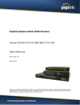
Peplink Balance Multi-WAN Bonding Routers
User Manual
For Model 20/30/210/310/380/580/710/1350
Peplink Balance Firmware 5.4
June 2012
Copyright & Trademarks Specifications are subject to change without prior notice. Copyright © 2012 Peplink International Ltd. All
Rights Reserved. Peplink and the Peplink logo are trademarks of Peplink International Ltd. Other brands or products mentioned
may be trademarks or registered trademarks of their respective owners.
USER MANUAL
Peplink Balance Series
TABLE OF CONTENTS
1
INTRODUCTION AND SCOPE ······························································································5
2
GLOSSARY ··························································································································6
3
PRODUCT COMPARISON CHART ························································································7
4
PRODUCT FEATURES ········································································································11
4.1
4.2
5
Supported Network Features ··································································································· 11
Other Supported Features ······································································································· 12
PACKAGE CONTENTS········································································································14
5.1
5.2
5.3
6
Peplink Balance 20 / 30 ··········································································································· 14
Peplink Balance 210 / 310 ······································································································· 14
Peplink Balance 380 / 580 / 710 / 1350 ···················································································· 14
PEPLINK BALANCE OVERVIEW ·························································································15
6.1
6.2
6.3
6.4
6.5
6.6
6.7
6.8
7
Peplink Balance 20 ·················································································································· 15
Peplink Balance 30 ·················································································································· 17
Peplink Balance 210 ················································································································ 19
Peplink Balance 310 ················································································································ 21
Peplink Balance 380 ················································································································ 22
Peplink Balance 580 ················································································································ 26
Peplink Balance 710 ················································································································ 29
Peplink Balance 1350 ·············································································································· 32
INSTALLATION··················································································································35
7.1
7.2
7.3
8
Preparation······························································································································ 35
Constructing the Network ········································································································· 35
Configuring the Network Environment ······················································································ 36
BASIC CONFIGURATION ···································································································37
8.1
8.2
8.3
Connecting to Web Admin Interface ························································································· 37
Configuration with Setup Wizard ······························································································ 38
Advanced Setup ······················································································································ 40
9
CONFIGURATION OF LAN INTERFACE ··············································································42
10
DROP-IN MODE················································································································46
11
CONFIGURATION OF WAN INTERFACE(S) ········································································49
11.1
11.2
11.3
11.4
11.5
11.6
12
Connection Method(s) ·········································································································· 51
Physical Interface Settings ··································································································· 57
WAN Health Check ·············································································································· 59
Bandwidth Allowance Monitor ······························································································· 62
Additional Public IP Settings ································································································· 63
Dynamic DNS Settings ········································································································· 64
BANDWIDTH BONDING SPEEDFUSIONTM ·········································································65
http://www.peplink.com
-2 / 193-
Copyright © 2012 Peplink
USER MANUAL
Peplink Balance Series
12.1
12.2
12.3
13
IPSEC VPN ························································································································72
13.1
13.2
14
IPsec VPN Settings ·············································································································· 72
IPsec Status························································································································· 75
MANAGEMENT OF OUTBOUND TRAFFIC TO WAN ··························································75
14.1
14.2
15
TM
SpeedFusion Settings ······································································································· 66
Peplink Balance Behind NAT Router ···················································································· 70
SpeedFusionTM Status·········································································································· 71
Outbound Policy··················································································································· 75
Custom Rules for Outbound Policy ······················································································· 77
INBOUND ACCESS ············································································································83
15.1
15.2
15.3
15.4
15.5
Definition of Port Forwarding ································································································ 83
Definition of Servers on LAN ································································································ 85
Inbound Access Services ····································································································· 86
Reverse Lookup Zones ······································································································ 100
DNS Record Import Wizard ································································································ 103
16
NAT MAPPINGS··············································································································106
17
WLAN CONTROLLER ·······································································································108
17.1
17.2
17.3
17.4
17.5
18
QOS ································································································································129
18.1
18.2
18.3
19
Outbound and Inbound Firewall Rules ················································································ 133
Web Blocking ····················································································································· 139
MISCELLANEOUS SETTINGS····························································································140
20.1
20.2
20.3
20.4
21
User Groups······················································································································· 129
Bandwidth Control ·············································································································· 130
Application ························································································································· 131
FIREWALL ·······················································································································133
19.1
19.2
20
WLAN Information ·············································································································· 108
AP Management ················································································································ 113
Wireless Networks ············································································································· 114
Captive Portal Management ······························································································· 119
AP Profile ··························································································································· 126
High Availability ·················································································································· 140
PPTP Server ······················································································································ 143
Service Forwarding ············································································································ 145
Service Passthrough ·········································································································· 147
SYSTEM SETTINGS ··········································································································148
21.1
21.2
21.3
21.4
21.5
21.6
Admin Security ··················································································································· 148
Firmware Upgrade ············································································································· 152
Time ·································································································································· 153
Email Notification ··············································································································· 154
Remote Syslog··················································································································· 156
SNMP ································································································································ 157
http://www.peplink.com
-3 / 193-
Copyright © 2012 Peplink
USER MANUAL
Peplink Balance Series
21.7
21.8
21.9
22
TOOLS ····························································································································161
22.1
22.2
22.3
22.4
23
InControl ···························································································································· 159
Configuration······················································································································ 160
Reboot ······························································································································· 161
Ping Test···························································································································· 161
Traceroute Test ·················································································································· 163
SpeedFusionTM Test ··········································································································· 163
CLI (Command Line Interface Support) ·············································································· 164
STATUS ··························································································································165
23.1
23.2
23.3
23.4
23.5
23.6
23.7
23.8
Device································································································································ 165
Active Sessions ·················································································································· 166
Client List ··························································································································· 168
Access Point ······················································································································ 169
WINS Client ······················································································································· 169
SpeedFusionTM Status ········································································································ 169
Event Log··························································································································· 170
Bandwidth ·························································································································· 171
APPENDIX A. RESTORATION OF FACTORY DEFAULTS ·····························································176
APPENDIX B. ROUTING UNDER DHCP, STATIC IP, AND PPPOE ···············································177
B.1
B.2
Routing via Network Address Translation (NAT)····································································· 177
Routing via IP Forwarding ······································································································ 178
APPENDIX C. CASE STUDIES ····································································································179
C.1
C.2
C.3
C.4
C.5
Performance Optimization ····································································································· 179
Maintaining the Same IP Address throughout a Session ························································ 181
Bypassing the Firewall to Access Hosts on LAN ···································································· 182
Inbound Access Restriction···································································································· 183
Outbound Access Restriction ································································································· 184
APPENDIX D. TROUBLESHOOTING··························································································185
APPENDIX E. PRODUCT SPECIFICATIONS ················································································187
E.1
E.2
E.3
E.4
E.5
E.6
Peplink Balance 20 and 30 ···································································································· 187
Peplink Balance 210 and 310 ································································································ 188
Peplink Balance 380 ·············································································································· 189
Peplink Balance 580 ·············································································································· 190
Peplink Balance 710 ·············································································································· 191
Peplink Balance 1350 ············································································································ 192
http://www.peplink.com
-4 / 193-
Copyright © 2012 Peplink
USER MANUAL
Peplink Balance Series
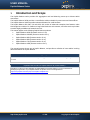
1
Introduction and Scope
The Peplink Balance series provides link aggregation and load balancing across up to thirteen WAN
connections.
The Peplink Balance 20/30 provides a cost-effective solution suitable for power users and home offices.
The Peplink Balance 210/310 provides advanced features for small business.
The Peplink Balance 380, 580, 710 and 1350, with a suite of advanced enterprise-class features, make
ideal single-box solutions for medium to large-sized business environments, and allow service providers
to enable highly available multi-network services.
This manual applies to the following Peplink Balance products:
Peplink Balance 20/30 (firmware version v5.4.x)
Peplink Balance 210/310 (firmware version v5.4.x)
Peplink Balance 380 (firmware version v5.4.x)
Peplink Balance 580 (firmware version v5.4.x)
Peplink Balance 710 (firmware version v5.4.x)
Peplink Balance 1350 (firmware version v5.4.x)
The manual presents how-to set up Peplink Balance, and provides a collection of case studies involving
advanced features of Peplink Balance.
Important Note to Users Upgrading from Firmware 4.7 or below
If your current firmware version is 4.7 or below, please upgrade to Firmware 4.8.2 first before upgrading to Firmware
5.3 or 5.4
Important Note to Users of Peplink Balance 30 (Classic Edition)
Firmware 5.0 or above is NOT applicable to Peplink Balance 30 (Classic Edition). For more information of
identifying the generation of your Peplink Balance 30, please visit our knowledge base at
<http://www.peplink.com/index.php?view=faq&id=231&path=16>.
http://www.peplink.com
-5 / 193-
Copyright © 2012 Peplink
USER MANUAL
Peplink Balance Series
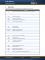
2
Glossary
The following terms, acronyms, and abbreviations are frequently used in this manual:
Term
Definition
3G
3rd Generation standards for wireless communications (e.g. HSDPA)
4G
4th Generation standards for wireless communications (e.g. WiMAX, LTE)
DHCP
DNS
EVDO
HSDPA
Dynamic Host Configuration Protocol
Domain Name System
Evolution-Data Optimized
High-Speed Downlink Packet Access
GRE
Generic Routing Encapsulation
HTTP
Hyper-Text Transfer Protocol
ICMP
Internet Control Message Protocol
IP
LAN
MAC Address
Internet Protocol
Local Area Network
Media Access Control Address
MTU
Maximum Transmission Unit
MSS
Maximum Segment Size
NAT
Network Address Translation
PPPoE
QoS
SNMP
Point to Point Protocol over Ethernet
Quality of Service
Simple Network Management Protocol
TCP
Transmission Control Protocol
UDP
User Datagram Protocol
VPN
Virtual Private Network
VRRP
Virtual Router Redundancy Protocol
WAN
Wide Area Network
WINS
Windows Internet Name Service
WLAN
Wireless Local Area Network
210+
Refer to Peplink Balance 210/310/380/580/710/1350
380+
Refer to Peplink Balance 380/580/710/1350
http://www.peplink.com
-6 / 193-
Copyright © 2012 Peplink
USER MANUAL
Peplink Balance Series
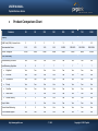
3
Product Comparison Chart
Features
20
30
210
310
380
580
710
1350
WAN Ports (GbE) / Internet Links
2
3
2
3
3
5
7
13
Recommended Users
1-25
1-25
1-50
1-50
50-500
300-1000
500-2000+
1000-5000+
Router Throughput
100M
100M
100M
100M
200M
400M
800M
1500M
Load Balancing & Failover
Yes
Yes
Yes
Yes
Yes
Yes
Yes
Yes
Load Balancing Algorithms
5
5
7
7
7
7
7
7
Capacity
Core Functionality
Weighted
Yes
Yes
Yes
Yes
Yes
Yes
Yes
Yes
Enforced
Yes
Yes
Yes
Yes
Yes
Yes
Yes
Yes
Persistence
Yes
Yes
Yes
Yes
Yes
Yes
Yes
Yes
Priority
Yes
Yes
Yes
Yes
Yes
Yes
Yes
Yes
Overflow
Yes
Yes
Yes
Yes
Yes
Yes
Yes
Yes
Least Used
X
X
Yes
Yes
Yes
Yes
Yes
Yes
Lowest Latency
X
X
Yes
Yes
Yes
Yes
Yes
Yes
Drop-In Mode
X
X
Yes
Yes
Yes
Yes
Yes
Yes
Inbound Load Balancing
X
X
Yes
Yes
Yes
Yes
Yes
Yes
4G/3G Modem Support
Yes
Yes
Yes
Yes
Yes
Yes
Yes
Yes
http://www.peplink.com
-7 / 193 -
Copyright © 2012 Peplink
USER MANUAL
Peplink Balance Series
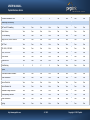
VPN Functionality
TM
SpeedFusion
X
X
Yes
Yes
Yes
Yes
Yes
Yes
Number of SpeedFusionTM Peer
Peers
Bonded VPN Throughput
X
X
2
2
20
50
300
800
X
X
30M
30M
60M
80M
150M
350M
Yes
Yes
Yes
Yes
Yes
Yes
Yes
Yes
Recommended PPTP VPN Users
3
3
15
15
50
100
200
500
RADIUS / LDAP support for
PPTP
X
X
Yes
Yes
Yes
Yes
Yes
Yes
Yes
Yes
Yes
Yes
Yes
Yes
Yes
Yes
2
2
2
2
20
50
150
400
Manage Pepwave AP One
X
X
X
X
Yes
Yes
Yes
Yes
Access Point Configuration
X
X
X
X
Yes
Yes
Yes
Yes
AP Firmware Update
X
X
X
X
Yes
Yes
Yes
Yes
Number of AP Support
X
X
X
X
50*
100*
250*
500*
Bandwidth Usage Monitor
Yes
Yes
Yes
Yes
Yes
Yes
Yes
Yes
QoS for VoIP and E-Commerce
Yes
Yes
Yes
Yes
Yes
Yes
Yes
Yes
Application Prioritization
X
X
Yes
Yes
Yes
Yes
Yes
Yes
Application Prioritization by User
Group
User Group Bandwidth
Reservation
X
X
X
X
Yes
Yes
Yes
Yes
X
X
X
X
Yes
Yes
Yes
Yes
PPTP VPN Server
IPsec VPN
(Network-to-Network)
Number of IPsec Tunnel
WLAN Control Functionality
Advanced QoS Functionality
http://www.peplink.com
-8 / 193 -
Copyright © 2012 Peplink
USER MANUAL
Peplink Balance Series
Individual Bandwidth Limit
X
X
X
X
Yes
Yes
Yes
Yes
NAT and IP Forwarding
Yes
Yes
Yes
Yes
Yes
Yes
Yes
Yes
Static Routes
Yes
Yes
Yes
Yes
Yes
Yes
Yes
Yes
Port Forwarding
Yes
Yes
Yes
Yes
Yes
Yes
Yes
Yes
Many to One, One to One NAT
Yes
Yes
Yes
Yes
Yes
Yes
Yes
Yes
NAT Pool
Yes
Yes
Yes
Yes
Yes
Yes
Yes
Yes
SIP ALG, H.323 ALG
Yes
Yes
Yes
Yes
Yes
Yes
Yes
Yes
UPnP, NAT-PMP
Yes
Yes
Yes
Yes
Yes
Yes
Yes
Yes
WINS Server
Yes
Yes
Yes
Yes
Yes
Yes
Yes
Yes
Dynamic DNS
Yes
Yes
Yes
Yes
Yes
Yes
Yes
Yes
Web Blocking
X
X
X
X
Yes
Yes
Yes
Yes
Device
Management
Web Administrative Interface
Functionality
Yes
Yes
Yes
Yes
Yes
Yes
Yes
Yes
Email Notification
Yes
Yes
Yes
Yes
Yes
Yes
Yes
Yes
Active Client List
Yes
Yes
Yes
Yes
Yes
Yes
Yes
Yes
Active Session List
Yes
Yes
Yes
Yes
Yes
Yes
Yes
Yes
Bandwidth Usage Statistics
Yes
Yes
Yes
Yes
Yes
Yes
Yes
Yes
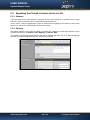
Web Reporting Services
Yes
Yes
Yes
Yes
Yes
Yes
Yes
Yes
Email Notification
Yes
Yes
Yes
Yes
Yes
Yes
Yes
Yes
Syslog
Yes
Yes
Yes
Yes
Yes
Yes
Yes
Yes
Networking Functionality
http://www.peplink.com
-9 / 193 -
Copyright © 2012 Peplink
USER MANUAL
Peplink Balance Series
SNMP v1, v2c and v3
Yes
Yes
Yes
Yes
Yes
Yes
Yes
Yes
4
4
4
4
1
1
1
1
100V to 240V
AC
15W
100V to 240V
AC
15W
100V to 240V
AC
15W
100V to 240V
AC
15W
100V to 240V
AC
50W
100V to 240V
AC
50W
100V to 240V
AC
70W
100V to 240V
AC
70W
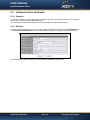
1U Rackmount
X
X
Yes
Yes
Yes
Yes
Yes
Yes
High Availability
X
X
Yes
Yes
Yes
Yes
Yes
Yes
LAN Bypass
X
X
X
X
X
Yes
Yes
Yes
Hardware Features
LAN Ports (GbE)
Power Input
Power Consumption
Dimension (H x W x D)
3.5cm x 26cm x 13.3cm
Weight
1.0kg
http://www.peplink.com
1.0kg
1U x 15.9cm
1.2kg
1U x 27.8cm
1.2kg
-10 / 193 -
3.5kg
1U x 37.9cm
5.5kg
1U x 39.8cm
5.5kg
Copyright © 2012 Peplink
6.5kg
USER MANUAL
Peplink Balance Series
Product Features
4
Peplink Balance Series products enable all LAN users to share broadband Internet connections, and
provide advanced features to enhance Internet access. The following is the list of supported features:
4.1
Supported Network Features
4.1.1 WAN
Multiple public IP support (DHCP, PPPoE, Static IP Address)
10/100/1000 Mbps Ethernet connection in Full/Half Duplex
USB mobile connection (Remark: Only one USB modem can be connected at a time.)
Drop-in Mode on selectable WAN port with MAC address passthrough (Available on Peplink
Balance 210+)
Network Address Translation (NAT) / Port Address Translation (PAT)
Inbound and Outbound NAT mapping
Multiple static IP addresses per WAN Connection
MAC address clone
Customizable MTU and MSS values
WAN connection health check
Dynamic DNS (Supported service providers: changeip.com, dyndns.org, no-ip.org, tzo.com and
DNS-O-Matic)
Ping, DNS Lookup and HTTP based health check
4.1.2 LAN
DHCP server on LAN
Static routing rules
Local DNS proxy server
4.1.3 VPN
Secure SpeedFusionTM (Available on Peplink Balance 210+)
Bandwidth bonding &failover among selected WAN connections
Ability to route traffic to a remote VPN peer
Optional pre-shared key setting
Layer 2 Bridging
SpeedFusionTM Throughput, Ping and Traceroute Test
Built-in PPTP VPN Server
Authenticate PPTP clients by RADIUS and LDAP servers (Available on Peplink Balance 210+)
IPsec VPN for Network-to-Network connection (Works with Cisco, Juniper only)
PPTP and IPsec passthrough
4.1.4 Inbound Traffic Management
TCP/UDP traffic redirection to dedicated LAN server(s)
Inbound link load balancing by means of DNS (Available on Peplink Balance 210+)
http://www.peplink.com
-11 / 193 -
Copyright © 2012 Peplink
USER MANUAL
Peplink Balance Series
4.1.5 Outbound Policy
Link load distribution per TCP/UDP service
Persistent routing for specified source and/or destination IP addresses per TCP/UDP service
Prioritize and route traffic to VPN tunnels with Priority and Enforced algorithms
4.1.6 WLAN Controller
Configure and manage Pepwave AP devices
Review the status of connected AP
4.1.7 QoS (Available on Peplink Balance 210+)
Quality of Service for different applications and custom protocols
User Group classification for different service levels (Available on Peplink Balance 380+)
Bandwidth usage control and monitoring on group- and user- level (Available on Peplink
Balance 380+)
Application Prioritization for custom protocols and DSL optimization
4.1.8 Firewall
4.2
Outbound (LAN to WAN) firewall rules
Inbound (WAN to LAN) firewall rules per WAN connection
Intrusion detection and prevention
Specification of NAT mappings
Web Blocking (Available on Peplink Balance 380+)
Outbound firewall rules can be defined by destination domain name
Other Supported Features
Easy-to-use web administration interface
HTTP and HTTPS support for Web Administration Interface
Configurable web administration port and administrator password
Read-only user for Web Admin
Authentication and Accounting by RADIUS server for Web Admin (Available on Peplink
Balance 210+)
Firmware upgrades, configuration backups, Ping, and Traceroute via Web Administration
Interface
Remote web based configuration (via WAN and LAN interfaces)
Remote reporting to Peplink Balance reporting server
Hardware High Availability via VRRP, with automatic configuration synchronization (Available on
Peplink Balance 210+)
Real-Time, Hourly, Daily and Monthly Bandwidth Usage reports and charts
Hardware backup via LAN bypass (Available on Peplink Balance 580 and 1350)
Built-in WINS server
Time server synchronization
SNMP
Email notification
Syslog
SIP passthrough
http://www.peplink.com
-12 / 193 -
Copyright © 2012 Peplink
USER MANUAL
Peplink Balance Series
PPTP packet passthrough
Active Sessions
Active Client List
WINS Client List
UPnP / NAT-PMP
Improved Active Sessions Page
Event Log is persistent across reboots
IPv6 support
Support USB tethering on Android 2.2+ phones
http://www.peplink.com
-13 / 193 -
Copyright © 2012 Peplink
USER MANUAL
Peplink Balance Series
Package Contents
5
The contents of Peplink Balance product packages are as follows:
5.1
5.2
5.3
Peplink Balance 20 / 30
Peplink Balance 20 / 30
Power adapter
Information slip
Peplink Balance 210 / 310
Peplink Balance 210 / 310
Power adapter
Information slip
Rackmount kit
Peplink Balance 380 / 580 / 710 / 1350
Peplink Balance 380/580/710/1350
Power cord
Information slip
Rackmount kit
http://www.peplink.com
-14 / 193 -
Copyright © 2012 Peplink
USER MANUAL
Peplink Balance Series
6
Peplink Balance Overview
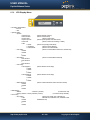
6.1
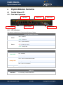
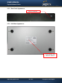
Peplink Balance 20
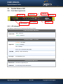
6.1.1 Front Panel Appearance
USB Port
WAN Ports
Reset Button
LAN Ports
Status LED
Power LED
6.1.2 LED Indicators
The statuses indicated by the Front Panel LEDs are as follows:
Power and Status Indicators
OFF – Power off
Power
Green – Power on
OFF – System initializing
Status
Red – Booting up or busy
Green – Ready state
LAN and WAN Ports
ON – 100 Mbps
Green LED
OFF – 10 Mbps
Solid – Port is connected without traffic
Orange LED
Blinking – Data is transferring
OFF – Port is not connected
Port Type
Auto MDI/MDI-X ports
USB Port
USB Ports
For connecting a 4G/3G USB modem.
http://www.peplink.com
-15 / 193 -
Copyright © 2012 Peplink
USER MANUAL
Peplink Balance Series
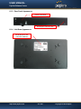
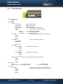
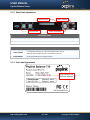
6.1.3 Rear Panel Appearance
Power Connector
Kensington Security Slot
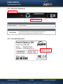
6.1.4 Unit Base Appearance
Serial Number and
LAN MAC Address
http://www.peplink.com
-16 / 193 -
Copyright © 2012 Peplink
USER MANUAL
Peplink Balance Series
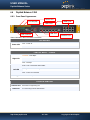
6.2
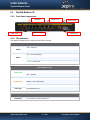
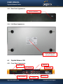
Peplink Balance 30
6.2.1 Front Panel Appearance
USB Port
WAN Ports
Reset Button
LAN Ports
Status LED
Power LED
6.2.2 LED Indicators
The statuses indicated by the Front Panel LEDs are as follows:
Power and Status Indicators
OFF – Power off
Power
GREEN – Power on
OFF – System initializing
Status
RED – Booting up or busy
GREEN – Ready state
LAN and WAN Ports
ON – 100 Mbps
Green LED
OFF – 10 Mbps
Solid – Port is connected without traffic
Orange LED
Blinking – Data is transferring
OFF – Port is not connected
Port Type
Auto MDI/MDI-X ports
USB Port
USB Ports
For connecting a 4G/3G USB modem.
http://www.peplink.com
-17 / 193 -
Copyright © 2012 Peplink
USER MANUAL
Peplink Balance Series
6.2.3 Rear Panel Appearance
Power Connector
Kensington Security Slot
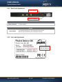
6.2.4 Unit Base Appearance
Serial Number and
LAN MAC Address
http://www.peplink.com
-18 / 193 -
Copyright © 2012 Peplink
USER MANUAL
Peplink Balance Series
6.3
Peplink Balance 210
6.3.1 Front Panel Appearance
WAN Ports
USB
LAN Ports
Status LED
Power LED
Reset Button
6.3.2 LED Indicators
The statuses indicated by the Front Panel LEDs are as follows:
Power and Status Indicators
OFF – Power off
Power
GREEN – Power on
OFF – System initializing
Status
RED – Booting up or busy
GREEN – Ready state
LAN and WAN Ports
ON – 100 Mbps
Green LED
OFF – 10 Mbps
Solid – Port is connected without traffic
Orange LED
Blinking – Data is transferring
OFF – Port is not connected
Port Type
Auto MDI/MDI-X ports
USB Port
USB Ports
For connecting a 4G/3G USB modem.
http://www.peplink.com
-19 / 193 -
Copyright © 2012 Peplink
USER MANUAL
Peplink Balance Series
6.3.3 Rear Panel Appearance
Power Connector
6.3.4 Unit Base Appearance
Serial Number and
LAN MAC Address
http://www.peplink.com
-20 / 193 -
Copyright © 2012 Peplink
USER MANUAL
Peplink Balance Series
6.4
Peplink Balance 310
6.4.1 Front Panel Appearance
USB
WAN Ports
LAN Ports
Status LED
Power LED
Reset Button
6.4.2 LED Indicators
The statuses indicated by the Front Panel LEDs are as follows:
Power and Status Indicators
OFF – Power off
Power
GREEN – Power on
OFF – System initializing
Status
RED – Booting up or busy
GREEN – Ready state
LAN and WAN Ports
ON – 100 Mbps
Green LED
OFF – 10 Mbps
Solid – Port is connected without traffic
Orange LED
Blinking – Data is transferring
OFF – Port is not connected
Port Type
Auto MDI/MDI-X ports
USB Port
USB Ports
For connecting a 4G/3G USB modem.
http://www.peplink.com
-21 / 193 -
Copyright © 2012 Peplink
USER MANUAL
Peplink Balance Series
6.4.3 Rear Panel Appearance
Power Connector
6.4.4 Unit Base Appearance
Serial Number and
LAN MAC Address
6.5
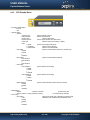
Peplink Balance 380
6.5.1 Front Panel Appearance
LAN Port
Power LED
LCD Display
LCD Controls
http://www.peplink.com
RS-232
WAN Ports
Port
USB Ports
Console
-22 / 193 -
RS-232
Copyright © 2012 Peplink
Port
USER MANUAL
Peplink Balance Series
6.5.2 LED Indicators
The statuses indicated by the Front Panel LEDs are as follows:
Power and Status Indicators
Power LED
OFF – Power off
GREEN – Power on
LAN Port, WAN 1 – 3 Ports
ORANGE – 1000 Mbps
Right LED
GREEN – 100 Mbps
OFF – 10 Mbps
Solid – Port is connected without traffic
Left LED
Blinking – Data is transferring
OFF – Port is not connected
Port Type
Auto MDI/MDI-X ports
Console and USB Ports
Console Port
USB Ports
Reserved for engineering use
For connecting a 4G/3G USB modem.
http://www.peplink.com
-23 / 193 -
Copyright © 2012 Peplink
USER MANUAL
Peplink Balance Series
6.5.3
LCD Display Menu
> HA State: Master/Slave
> LAN IP
> VIP
> System Status
> System
> Firmware ver.
(shows firmware version)
> Serial number
(shows serial number)
> System time
(shows current time)
> System up time
(shows system uptime since last reboot)
> CPU load
(shows current CPU loading, 0-100%)
> LAN
> Status
(shows LAN port physical status)
> IP address
(shows LAN IP address)
> Subnet mask (shows LAN subnet mask)
> Link status
(shows Connected/Disconnected, IP address list)
> WAN1
> WAN2
> WAN3
> VPN status
(shows Connected/Disconnected)
>VPN Profile 1
>VPN Profile 2
>…
>VPN Profile n
> Link usage
> Throughput in
(shows transfer rate in Kbps)
> WAN1
> WAN2
> WAN3
> Throughput out
(shows transfer rate in Kbps)
> WAN1
> WAN2
> WAN3
> Data Transfer’d
(shows volume transferred since last reboot in MB)
> WAN1
> WAN2
> WAN3
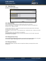
> Maintenance
> Reboot
> Reboot? (Yes/No)
(to reboot the unit)
> Factory default
> Factory default? (Yes/No)
(to restore factory defaults)
> LAN config
> Port speed
(shows port speed: Auto, 10baseT-FD, 10baseT-HD,
> LAN
100baseTx-FD, 100baseTx-HD, 1000baseTx-FD)
> WAN1
> WAN2
> WAN3
http://www.peplink.com
-24 / 193 -
Copyright © 2012 Peplink
USER MANUAL
Peplink Balance Series
6.5.4 Rear Panel Appearance
Power Switch
Power Connector
Connector Ports
Power Connector
AC input 110/220V
Switch
Power Switch
To hold pressing the key for 4 seconds will power down the unit
When the unit is powered off, press it will power on the unit
6.5.5 Unit Label Appearance
Serial Number and
LAN MAC Address
http://www.peplink.com
-25 / 193 -
Copyright © 2012 Peplink
USER MANUAL
Peplink Balance Series
6.6
Peplink Balance 580
6.6.1 Front Panel Appearance
WAN Ports
Power LED
LAN Port
USB Ports
RS-232
Port
LCD Display
RS-232
Port
Console
LCD Controls
6.6.2 LED Indicators
The statuses indicated by the Front Panel LEDs are as follows:
Power and Status Indicators
OFF – Power off
Power LED
GREEN – Power on
LAN Port, WAN 1 – 5 Ports
ORANGE – 1000 Mbps
Right LED
GREEN – 100 Mbps
OFF – 10 Mbps
Solid – Port is connected without traffic
Left LED
Blinking – Data is transferring
OFF – Port is not connected
Port Type
Auto MDI/MDI-X ports
Console and USB Ports
Console Port
USB Ports
Reserved for engineering use
For connecting a 4G/3G USB modem.
http://www.peplink.com
-26 / 193 -
Copyright © 2012 Peplink
USER MANUAL
Peplink Balance Series
6.6.3
LCD Display Menu
> HA State: Master/Slave
> LAN IP
> VIP
> System Status
> System
> Firmware ver.
(shows firmware version)
> Serial number
(shows serial number)
> System time
(shows current time)
> System up time
(shows system uptime since last reboot)
> CPU load
(shows current CPU loading, 0-100%)
> LAN
> Status
(shows LAN port physical status)
> IP address
(shows LAN IP address)
> Subnet mask (shows LAN subnet mask)
> Link status
(shows Connected/Disconnected, IP address list)
> WAN1
> WAN2
>…
>WAN5
> VPN status
(shows Connected/Disconnected)
>VPN Profile 1
>VPN Profile 2
>…
>VPN Profile n
> Link usage
> Throughput in
(shows transfer rate in Kbps)
> WAN1
> WAN2
>…
>WAN5
> Throughput out
(shows transfer rate in Kbps)
> WAN1
> WAN2
>…
>WAN5
> Data Transfer’d
(shows volume transferred since last reboot in MB)
> WAN1
> WAN2
>…
>WAN5
> Maintenance
> Reboot
> Reboot? (Yes/No)
(to reboot the unit)
> Factory default > Factory default? (Yes/No)
(to restore factory defaults)
> LAN config
> Port speed
(shows port speed: Auto, 10baseT-FD, 10baseT-HD,
> LAN
100baseTx-FD, 100baseTx-HD, 1000baseTx-FD)
> WAN1
> WAN2
>…
>WAN5
http://www.peplink.com
-27 / 193 -
Copyright © 2012 Peplink
USER MANUAL
Peplink Balance Series
6.6.4 Rear Panel Appearance
Power Switch
Power Connector
Connector Ports
Power Connector
AC input 110/220V
Switch
Power Switch
To hold pressing the key for 4 seconds will power down the unit
When the unit is powered off, press it will power on the unit
6.6.5 Unit Label Appearance
Serial Number and
LAN MAC Address
http://www.peplink.com
-28 / 193 -
Copyright © 2012 Peplink
USER MANUAL
Peplink Balance Series
6.7
Peplink Balance 710
6.7.1 Front Panel Appearance
USB Ports
LCD Display
WAN Port
RS-232
Port
LCD Controls
LAN Ports
Console Port Power LED
Status indicated in the Front Panel is as follows:
RS-232 Port
LED Indicator
Power LED
OFF – Power off
GREEN – Power on
LAN Port, WAN 1 – 7Ports
Green LED
ON – 1000 Mbps
OFF – 100/10 Mbps
Solid – Port is connected without traffic
Orange LED
Blinking – Data is transferring
OFF – Port is not connected
Port Type
Auto MDI/MDI-X ports
Console & USB Ports
Console Port
USB Ports
Reserved for engineering use
For connecting a 4G/3G USB modem.
http://www.peplink.com
-29 / 193 -
Copyright © 2012 Peplink
USER MANUAL
Peplink Balance Series
6.7.2
LCD Display Menu
> HA State: Master/Slave
>LAN IP
> VIP
> System Status
> System
> Firmware ver.
(shows firmware version)
> Serial number
(shows serial number)
> System time
(shows current time)
> System up time
(shows system uptime since last reboot)
> CPU load
(shows current CPU loading, 0-100%)
> LAN
> Status
(shows LAN port physical status)
> IP address
(shows LAN IP address)
> Subnet mask
(shows LAN subnet mask)
> Link status
(shows Connected/Disconnected, IP address list)
> WAN1
> WAN2
>…
> WAN7
> VPN status
(shows Connected/Disconnected)
>VPN Profile 1
>VPN Profile 2
>…
>VPN Profile n
> Link usage
> Throughput in
(shows transfer rate in Kbps)
> WAN1
> WAN2
>…
> WAN7
> Throughput out
(shows transfer rate in Kbps)
> WAN1
> WAN2
>…
> WAN7
> Data Transfer’d
(shows volume transferred since last reboot in MB)
> WAN1
> WAN2
>…
> WAN7
> Maintenance
> Reboot
> Reboot? (Yes/No)
(to reboot the unit)
> Factory default > Factory default? (Yes/No)
(to restore factory defaults)
> LAN config
> Port speed
(shows port speed: Auto, 10baseT-FD,
> LAN
10baseT-HD, 100baseTx-FD, 100baseTx-HD,
> WAN1
1000baseTx-FD)
> WAN2
>…
> WAN7
http://www.peplink.com
-30 / 193 -
Copyright © 2012 Peplink
USER MANUAL
Peplink Balance Series
6.7.3 Rear Panel Appearance
Reset Switch
Power Switch
Power Connector
RS-232 Port
Connector Ports
RS-232 Port
Power Connector
Reserved for engineering use
AC input 110/220V
Switches
Power Switch
To hold pressing the key for 4 seconds will power down the unit
When the unit is powered off, press it will power on the unit
Reset Switch
Press and release once to reset the system
6.7.4 Unit Label Appearance
Serial Number and
LAN MAC Address
http://www.peplink.com
-31 / 193 -
Copyright © 2012 Peplink
USER MANUAL
Peplink Balance Series
6.8
Peplink Balance 1350
6.8.1 Front Panel Appearance
Power LED
WAN Ports
LCD Display
USB Ports
LAN Port
LCD Controls
Status indicated in the Front Panel is as follows:
LED Indicator
Power LED
Console Port
RS-232
Port
RS-232 Port
OFF – Power off
GREEN – Power on
LAN Port, WAN 1 – 13 Ports
ORANGE – 1000 Mbps
Right LED
GREEN – 100 Mbps
OFF – 10 Mbps
Solid – Port is connected without traffic
Left LED
Blinking – Data is transferring
OFF – Port is not connected
Port Type
Auto MDI/MDI-X ports
Console & USB Ports
Console Port
USB Ports
Reserved for engineering use
For connecting a 4G/3G USB modem.
http://www.peplink.com
-32 / 193 -
Copyright © 2012 Peplink
USER MANUAL
Peplink Balance Series
6.8.2
LCD Display Menu
> HA State: Master/Slave
>LAN IP
> VIP
> System Status
> System
> Firmware ver.
(shows firmware version)
> Serial number
(shows serial number)
> System time
(shows current time)
> System up time
(shows system uptime since last reboot)
> CPU load
(shows current CPU loading, 0-100%)
> LAN
> Status
(shows LAN port physical status)
> IP address
(shows LAN IP address)
> Subnet mask
(shows LAN subnet mask)
> Link status
(shows Connected/Disconnected, IP address list)
> WAN1
> WAN2
>…
> WAN13
> VPN status
(shows Connected/Disconnected)
>VPN Profile 1
>VPN Profile 2
>…
>VPN Profile n
> Link usage
> Throughput in
(shows transfer rate in Kbps)
> WAN1
> WAN2
>…
> WAN13
> Throughput out
(shows transfer rate in Kbps)
> WAN1
> WAN2
>…
> WAN13
> Data Transfer’d
(shows volume transferred since last reboot in MB)
> WAN1
> WAN2
>…
> WAN13
> Maintenance
> Reboot
> Reboot? (Yes/No)
(to reboot the unit)
> Factory default > Factory default? (Yes/No)
(to restore factory defaults)
> LAN config
> Port speed
(shows port speed: Auto, 10baseT-FD, 10baseT-HD,
> LAN
100baseTx-FD, 100baseTx-HD,1000baseTx-FD)
> WAN1
> WAN2
>…
> WAN13
http://www.peplink.com
-33 / 193 -
Copyright © 2012 Peplink
USER MANUAL
Peplink Balance Series
6.8.3 Rear Panel Appearance
Power Switch
Power Connector
Connector Ports
Power Connector
AC input 110/220V
Switches
Power Switch
To hold pressing the key for 4 seconds will power down the unit
When the unit is powered off, press it will power on the unit
6.8.4 Unit Label Appearance
Serial Number and
LAN MAC Address
http://www.peplink.com
-34 / 193 -
Copyright © 2012 Peplink
USER MANUAL
Peplink Balance Series
Installation
7
Connecting the Network with Peplink Balance:
7.1
Preparation
Before installing Peplink Balance, please prepare the following:
At least one Internet/WAN access account.
For each network connection, one 10/100 BaseT UTP cable with RJ45 connector, or one 1000
BaseT Cat5E UTP cable for the Gigabit port on the Balance 580/710/1350, or one USB modem
for the USB WAN port on Balance 380/580/710/1350.
A computer with TCP/IP network protocol and a web browser installed. Supported browsers
include Microsoft Internet Explorer 8.0 or above, Mozilla Firefox 10.0 or above, Apple Safari 5.1
or above, and Google Chrome 18 or above.
7.2
Constructing the Network
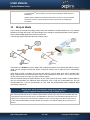
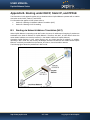
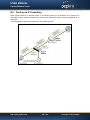
At the high level, construct the network according to the following steps:
1. With an Ethernet cable, connect a computer to one of the LAN ports on the Peplink Balance. For
Peplink Balance 20, 30, 210 and 310, repeat with different cables for up to 4 computers to be
connected.
2.
With another Ethernet cable, connect the WAN/broadband modem to one of the WAN ports on
the Peplink Balance. Repeat using different cables to connect up to 2, 3, 5, 7 or
13WAN/broadband connections with the Peplink Balance 20, 30, 210, 310, 380, 580,710 and
1350, respectively, or connect a USB modem to the USB WAN port on the Peplink Balance
20/30/380/580/710/1350.
3.
For Peplink Balance 20, 30, 210and 310, connect the provided power adapter to the power
connector on the Peplink Balance, and then plug the power adapter into a power outlet. For
Peplink Balance 380, 580, 710 and 1350, connect the provided power cord to the AC power
connector on the Peplink Balance, and then plug the power cord into a power outlet.
The following figure schematically illustrates the configuration that results:
http://www.peplink.com
-35 / 193 -
Copyright © 2012 Peplink
USER MANUAL
Peplink Balance Series
7.3
Configuring the Network Environment
To ensure that Peplink Balance works properly in the LAN environment and can access the Internet via
the WAN connections, please refer to the following setup procedures:
LAN Configuration
For basic configuration, refer to Section 8, Basic Configuration.
For advanced configuration, refer to Section 9, Configuration of LAN Interface.
WAN Configuration
For basic configuration, refer to Section 8, Basic Configuration.
For advanced configuration, refer to Section 11, Configuration of WAN Interface(s).
http://www.peplink.com
-36 / 193 -
Copyright © 2012 Peplink
USER MANUAL
Peplink Balance Series
8
Basic Configuration
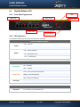
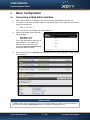
8.1
Connecting to Web Admin Interface
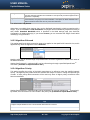
1.
Start a web browser on a computer that is connected with Peplink Balance through LAN.
2.
To connect to Web Admin of Peplink Balance, enter the following LAN IP address in the address
field of the web browser:
http://192.168.1.1
(This is the default LAN IP address of Peplink Balance)
3.
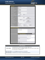
Enter the following to access the Web
Admin Interface.
User Name: admin
Password: admin
(This is the default Admin User login of
Peplink Balance. The Admin and
Read-only User Password can be
changed at System > Admin Security
of the Web Admin Interface.)
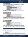
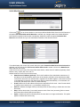
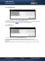
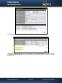
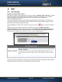
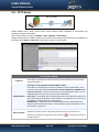
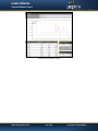
4.
After successful login, the Dashboard of Web Admin Interface will be displayed. It looks similar
to the following:
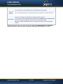
Important Note
The Save button causes the changes to be saved. Configuration changes (e.g. WAN, LAN, Admin settings, etc.)
take effect after clicking the Apply Changes button on each page’s top right hand corner.
http://www.peplink.com
-37 / 193 -
Copyright © 2012 Peplink
USER MANUAL
Peplink Balance Series
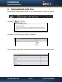
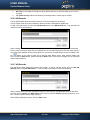
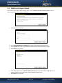
8.2
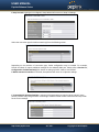
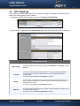
Configuration with Setup Wizard
The Setup Wizard of Peplink Balance simplifies the task of configuring WAN connection(s) by guiding the
configuration process step by step.
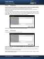
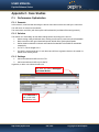
To begin, click Setup Wizard after connecting to Web Admin Interface.
Click Next
to begin.
Select YES if you want to set up Drop-in mode in Setup Wizard.
(Note: Drop-in mode is available on Peplink Balance 210+.)
Click on the appropriate check box(es) to select the WAN connection(s) to be configured. If you have
chosen to configure Drop-in mode in Setup Wizard, the box of WAN port that is to be configured in Dropin mode will be checked by default.
http://www.peplink.com
-38 / 193 -
Copyright © 2012 Peplink
USER MANUAL
Peplink Balance Series
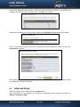
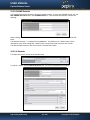
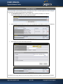
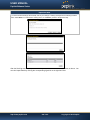
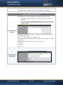
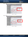
If Drop-in mode is going to be configured, Setup Wizard will move on to Drop-in Settings.
Select the connection type for WAN connection(s) from the following screen:
Depending on the selection of connection type, further configuration may be needed. For example,
PPPoE and Static IP require additional settings for the selected WAN port. Please refer to Section 11,
Configuration of WAN Interface(s) for details on setting up DHCP, Static IP and PPPoE.
If Mobile Internet Connection is checked, Setup Wizard will move on to Operator settings.
If Custom Mobile Operator Settings is selected, APN parameters are required to be entered. Some
service providers may charge a fee for connecting to a different APN. Please consult the service provider
for the correct settings.
http://www.peplink.com
-39 / 193 -
Copyright © 2012 Peplink
USER MANUAL
Peplink Balance Series
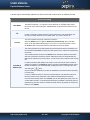
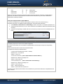
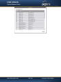
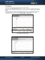
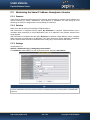
Click on the appropriate check box(es) to select the preferred WAN connection(s). Connection(s) not
selected in this step will be used as back up only. Click Next >> to continue.
Choose the time zone of your Country/Region. Check the box Show all to display all time zone options.
Check in the following screen to make sure all settings have been configured correctly, and then click
Save Settings to confirm.
After finishing the last step in the Setup Wizard, please click Apply Changes on the page header to allow
the configuration changes to take effect.
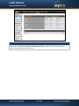
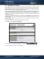
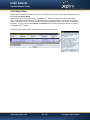
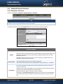
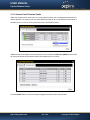
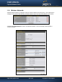
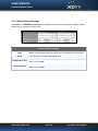
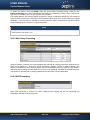
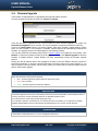
8.3
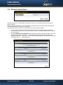
Advanced Setup
Advanced settings can be configured from the Network menu.
WAN connections can be configured by entering the corresponding WAN connection information at:
Network > Interfaces > WAN
http://www.peplink.com
-40 / 193 -
Copyright © 2012 Peplink
USER MANUAL
Peplink Balance Series
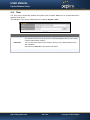
Tip
Please refer to Section 11, Configuration of WAN Interface(s), for details on setting up DHCP, Static IP,
PPPoE, GRE, and Mobile Internet Connection.
http://www.peplink.com
-41 / 193 -
Copyright © 2012 Peplink
USER MANUAL
Peplink Balance Series
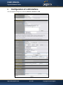
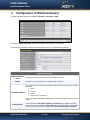
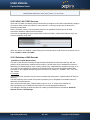
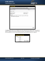
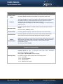
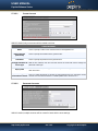
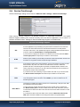
9
Configuration of LAN Interface
The LAN Interface settings are located at: Network > Interfaces > LAN
http://www.peplink.com
-42 / 193 -
Copyright © 2012 Peplink
USER MANUAL
Peplink Balance Series
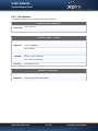
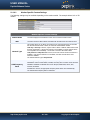
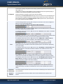
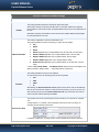
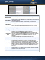
LAN Settings
IP Address &
Subnet Mask
The IP address of Peplink Balance on LAN
This setting specifies the speed of the LAN Ethernet Port.
Speed
By default, Auto is selected and the appropriate data speed is automatically detected by
Peplink Balance.
In the event of negotiation issues, the port speed can be manually specified to circumvent
the issues. You can also choose whether or not to advertise the speed to the peer by
selecting the Advertise Speed checkbox.
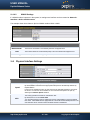
Drop-in Mode Settings
(Available on Peplink Balance 210+)
Enable
Drop-in Mode eases the installation of Peplink Balance on a live network between the
existing Firewall and Router, such that no configuration changes are required on existing
equipment. Check the box to enable the Drop-in Mode feature.
Please refer to Section 10
WAN for Drop-In
Mode
WAN Default
Gateway
Drop-in Mode for details.
Select the WAN port to be used for Drop-in mode. If the WAN port for LAN Bypass is
selected, High Availability feature will be disabled automatically.
Enter the WAN router's IP address in this field. If there are more hosts other than the router
on the WAN segment, check the box have other host(s) on WAN segment and enter the
IP address of the hosts that needs to access LAN devices or to be accessed by others.
WAN DNS Servers Enter the selected WAN's corresponding DNS server IP addresses.
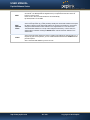
DHCP Server Settings
DHCP Server
When this setting is enabled, the DHCP server of Peplink Balance automatically assigns an
IP address to each computer that is connected via LAN and is configured to obtain an IP
address via DHCP.
Peplink Balance’s DHCP server can prevent IP address collision on LAN.
IP Range &
Subnet Mask
This setting allocates a range of IP address that will be assigned to LAN computers by the
DHCP server of Peplink Balance.
Lease Time
This setting specifies the length of time throughout which an IP address of a DHCP client
remains valid. Upon expiration of the Lease Time, the assigned IP address will no longer be
valid and the renewal of the IP address assignment will be required.
DNS Servers
This option allows you to input the DNS server addresses to be offered to the DHCP clients.
If Assign DNS server automatically is selected, the Peplink Balance’s built-in DNS server
address (i.e. LAN IP address) will be offered.
WINS Server
This option allows you to specify the Windows Internet Name Service (WINS) server. You
may choose to use the built-in WINS server or external WINS servers.
TM
When this unit is SpeedFusion connected, other VPN peers can share this unit's built-in
WINS server by entering this unit's LAN IP address in their DHCP WINS Servers setting.
http://www.peplink.com
-43 / 193 -
Copyright © 2012 Peplink
USER MANUAL
Peplink Balance Series
Therefore, all PC clients in the VPN can resolve the NetBIOS names of other clients in
remote peers.
If you have enabled this option, a list of WINS clients will be displayed at Status > WINS
Clients.
Extended DHCP
Option
In addition to standard DHCP options (e.g. DNS server address, gateway address, subnet
mask), you can specify the value of additional Extended DHCP Options defined in RFC
2132. In this case, you can pass additional configuration information to LAN hosts.
To define an Extended DHCP Option, click the Add button, choose the option that you want
to define and enter its value. For values that are in IP address list format, you can enter one
IP address per line in the provided text area input control. Each option is allowed to be
defined once only.
This setting reserves the assignment of fixed IP addresses for a list of computers on the
LAN. The computers to be assigned fixed IP addresses on the LAN are identified by their
MAC addresses.
The fixed IP address assignment is displayed as a cross-reference list between the
computers’ Name, MAC addresses and fixed IP addresses.
DHCP Reservation The field Name (an optional field) is for you to define a name to represent the device. MAC
addresses should be in the format of 00:AA:BB:CC:DD:EE
Press
to create a new record. Press
to remove a record.
Reserved clients information can be imported from the Client List, located at Status > Client
List. For more details, please refer to section 23.3
http://www.peplink.com
-44 / 193 -
Copyright © 2012 Peplink
USER MANUAL
Peplink Balance Series
Static Route Settings
Static Route
This table is for defining static routing rules for the LAN segment.
A static route consists of the network address, subnet mask, and gateway address. The
address and subnet mask values are in the format of w.x.y.z
The local LAN subnet and subnets behind the LAN will be advertised to the VPN. Remote
routes sent over the VPN will also be accepted. Any VPN member will be able to route to
the local subnets.
Press
to create a new route. Press
to remove a route.
WINS Server Settings
Enable
Check the box to enable the WINS Server. A list of WINS clients will be displayed at Status
> WINS Clients.
DNS Proxy Settings
A check box to enable to DNS Proxy feature.
Network > LAN > DNS Proxy Settings table
Enable
DNS Caching
Include Google
Public DNS
Servers
A DNS proxy server can be enabled to serve DNS requests originating from LAN/PPTP/
SpeedFusionTM peers. Requests are forwarded to the DNS servers/resolvers defined in
each WAN connection.
This field is to enable DNS caching on the built-in DNS proxy server. When the option is
enabled, queried DNS replies will be cached until the records’ TTL has been reached. This
feature can help improve the DNS lookup time by storing all received DNS results for a
faster DNS response time. However, it cannot return the most updated result for those
frequently updated DNS records.
By default, it is disabled.
When this option is enabled, the DNS proxy server will also forward DNS requests to
Google's Public DNS Servers in addition to the DNS servers defined in each WAN. This
could increase the DNS service's availability.
Default: disabled
This table is for defining custom local DNS records.
Local DNS
Records
A static local DNS record consists of a Host Name and an IP Address. When looking up the
Host Name from the LAN to LAN IP of Peplink Balance, the corresponding IP Address will
be returned.
Press
to create a new record. Press
to remove a record.
LAN DNS Resolver Settings
Enable
Check the box to enable the WINS Server. A list of WINS clients will be displayed at
Network > LAN > DNS Proxy Settings > DNS Resolvers.
This field specifies which DNS resolvers will receive forwarded DNS requests. If no
WAN/VPN/LAN DNS resolver is selected, all of the WAN’s DNS resolvers will be selected.
http://www.peplink.com
-45 / 193 -
Copyright © 2012 Peplink
USER MANUAL
Peplink Balance Series
TM
If a SpeedFusion
address(es).
peer is selected, you may enter the VPN peer’s DNS resolver IP
Queries will be forwarded to the selected connections’ resolvers. If all of the selected
connections are down, queries will be forwarded to all resolvers on healthy WAN
connections.
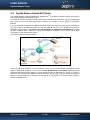
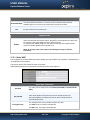
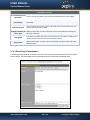
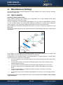
10
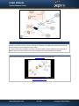
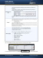
Drop-in Mode
Drop-in Mode (or transparent bridging mode) eases the installation of Peplink Balance on a live network
between the firewall and router, such that changes to the settings of existing equipment are not required.
Drop-in Mode is NOT applicable to Balance 20 and 30.
The following diagram illustrates the Drop-in Mode setup:
Check the box to Enable the Drop-in Mode. After enabling this feature and selecting the WAN for Drop-in
mode, various settings including the WAN's connection method and IP address will be automatically
updated.
When Drop-in Mode is enabled, the LAN and the WAN for Drop-in Mode ports will be bridged.Traffic
going in between the LAN hosts and WAN router will be forwarded to each other. In this case, the hosts
on both sides will not notice any IP or MAC address change.
After successfully setting up Peplink Balance as part of the network via Drop-in Mode, a Peplink Balance
210 will accommodate one additional WAN connection; 310 or 380 will accommodate two, 580 will
accommodate four, 710 will accommodate six, and 1350 will accommodate twelve additional WAN
connections respectively.
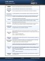
IMPORTANT NOTE for customers using Drop-in Mode and
going to upgrade from firmware 4.8.2 or below to 5.0+
MAC address passthrough for Drop-in Mode is implemented in firmware 5.0. If Drop-in Mode is enabled when user
is upgrading from previous firmware version, the ARP tables on the hosts on LAN and WAN segments have to be
flushed once or the hosts have to be rebooted. Otherwise, hosts on one side may not be able to reach hosts on
the other side of Peplink Balance until the old ARP records expire. Units without enabling Drop-in Mode are not
affected.
http://www.peplink.com
-46 / 193 -
Copyright © 2012 Peplink
USER MANUAL
Peplink Balance Series
NOTE
PPTP server will be disabled under Drop-in Mode.
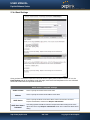
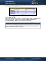
To enable Drop-in Mode, perform the following steps.
1.
2.
3.
Check the Enable box under Drop-in Mode located at: Network > Interfaces > LAN. (After
checking the Enable box, most network settings for WAN1 will be hidden from Web Administration
Interface.)
Put the IP address of the WAN1 router in the WAN Default Gateway field. Ensure that the Peplink
Balance IP subnet is the same as the Firewall’s WAN port and the Router’s LAN port.
If there are hosts other than the router existing on the WAN segment of Peplink Balance, check the
“I have other host(s) on WAN segment” box, enter the IP address(es) of the host(s), and then
click the down-arrow to add the hosts.
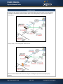
The following diagram illustrates:
http://www.peplink.com
-47 / 193 -
Copyright © 2012 Peplink
USER MANUAL
Peplink Balance Series
Important Note
Starting from firmware version 5.0, Drop-in mode can be configured on any WAN ports. Please be noted that still
only one WAN port can be configured in Drop-in mode.
If you have selected the LAN Bypass port (which is currently available on WAN1 of Balance 1350 and WAN5 of
Balance 580) as the WAN for Drop-in Mode, High Availability feature will be DISABLED automatically.
Tip
Want to know more about Drop-in mode? Visit our YouTube Channel for video tutorials!
http://youtu.be/lZG2-VPml5w
http://www.peplink.com
-48 / 193 -
Copyright © 2012 Peplink
USER MANUAL
Peplink Balance Series
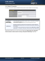
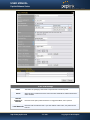
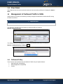
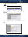
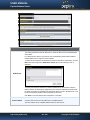
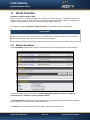
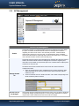
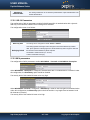
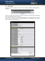
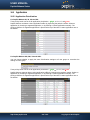
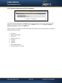
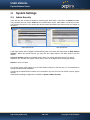
11
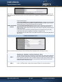
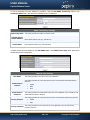
Configuration of WAN Interface(s)
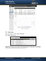
The WAN interface settings are located at: Network > Interfaces > WAN
By clicking a connection name, connection settings of that WAN can be modified.
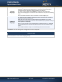
The connection method and details are determined by, and can be obtained from, the ISP.
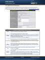
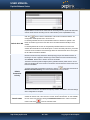
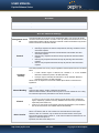
Connection Settings
WAN Connection
Name
This field is for defining a name to represent this WAN connection.
Enable
This field is for choosing whether to enable this WAN connection.
This option allows you to select the connection method for this WAN connection. Available
options are:
Connection Method
1.
DHCP
2.
Static IP
3.
PPPoE
4.
Mobile Internet Connection
See Sections 11.1.1, 11.1.2, 11.1.3 and 11.1.4 for configuration details of each connection
method.
Routing Mode
This field shows that NAT (Network Address Translation) will be applied to the traffic
routing over this WAN connection. IP Forwarding is also available when you click the link
in the help text. For further details, please refer to Appendix B, Routing under DHCP,
http://www.peplink.com
-49 / 193 -
Copyright © 2012 Peplink
USER MANUAL
Peplink Balance Series
Static IP, and PPPoE.
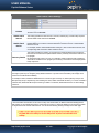
This setting specifies the utilization of the WAN connection.
Connection Type
The selection of Always-on results in the WAN connection to be used whenever it is
available. If Backup Priority and a priority group are selected, the WAN connection is
treated as a backup connection and is used only in the absence of available Always-on
WAN connection(s) and higher priority backup connection(s).
The default and recommended Connection Type is Always-on.
Reply to ICMP Ping
Upload Bandwidth
Download
Bandwidth
If this field is disabled, the WAN connection will not respond to ICMP Ping requests.
By default, this is enabled.
This setting specifies the data bandwidth in the outbound direction from the LAN through
the WAN interface. This value is provided by the ISP and should reflect the actual speed
the WAN gets.
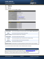
This value is referenced when default weight is chosen for outbound traffic and traffic
prioritization. A correct value can result in effective traffic prioritization and efficient use of
upload bandwidth.
This setting specifies the data bandwidth in the inbound direction from the WAN interface
to the LAN. This value is provided by the ISP and should reflect the actual speed the WAN
gets.
This value is referenced as the default weight value when using the algorithm Least Used,
or the algorithm Persistence (Auto) in Outbound Policy with Managed by Custom Rules
chosen (see Section 0).
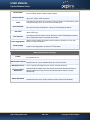
IPv6
IPv6 support can be enabled on one of the available Ethernet WAN ports. On this screen,
you can choose which WAN will support IPv6.
IPv6
To enable IPv6 support on a WAN, the WAN router must respond to Stateless Address
Auto configuration advertisements and DHCPv6 requests. IPv6 clients on the LAN will
acquire their IPv6, gateway, and DNS server addresses from it. The device will also
acquire an IPv6 address for performing ping/traceroute checks and accepting web admin
accesses.
http://www.peplink.com
-50 / 193 -
Copyright © 2012 Peplink
USER MANUAL
Peplink Balance Series
11.1 Connection Method(s)
There are four possible connection methods:
1. DHCP
2. Static IP
3. PPPoE
4. Mobile Internet Connection (for USB WAN)
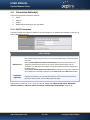
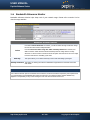
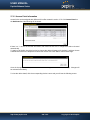
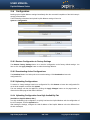
11.1.1 DHCP Connection
The DHCP connection method is suitable if the ISP provides an IP address automatically by DHCP (e.g.
Cable, Metro Ethernet, etc.).
DHCP Settings
DNS Servers
Hostname
(Optional)
Each ISP may provide a set of DNS servers for DNS lookups. This setting specifies the
DNS (Domain Name System) Servers to be used when a DNS lookup is routed through this
connection.
Selecting Obtain DNS server address automatically results in the DNS Servers to be
assigned by the WAN DHCP Server to be used for outbound DNS lookups over the
connection. (The DNS Servers are obtained along with the WAN IP address assigned from
the DHCP server.)
When Use the following DNS server address(es) is selected, you may enter custom DNS
server addresses for this WAN connection into the DNS server 1 and DNS server 2 fields.
If your service provider's DHCP server requires you to supply a hostname value upon
acquiring an IP address, you may enter the value here. If your service provider does not
provide you with the value, you can safely bypass this option.
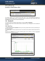
Please refer to Section 11.3, 11.4, 11.5, and 11.6 for details about WAN Health Check, Bandwidth
Allowance Monitor, Additional Public IP Settings, and Dynamic DNS Settings respectively.
http://www.peplink.com
-51 / 193 -
Copyright © 2012 Peplink
USER MANUAL
Peplink Balance Series
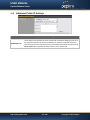
11.1.2 Static IP Connection
The Static IP connection method is suitable if the ISP provides a static IP address to connect directly.
Static IP Settings
IP Address /
Subnet Mask /
Default Gateway
These settings specify the information required in order to communicate on the Internet
via a fixed Internet IP address.
The information is typically determined by and can be obtained from the ISP.
DNS Servers
Each ISP may provide a set of DNS servers for DNS lookups. This field specifies the
DNS (Domain Name System) Servers to be used when a DNS lookup is routed through
this connection.
You can input the ISP provided DNS server addresses into the DNS server 1 and DNS
server 2 fields. If no address is entered here, this link will not be used for DNS lookups.
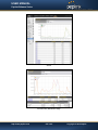
Please refer to Section 11.3, 11.4, 11.5, and 11.6 for details about WAN Health Check, Bandwidth
Allowance Monitor, Additional Public IP Settings, and Dynamic DNS Settings respectively.
http://www.peplink.com
-52 / 193 -
Copyright © 2012 Peplink
USER MANUAL
Peplink Balance Series
11.1.3 PPPoE Connection
This connection method is suitable if ISP provides login ID/ password to connect via PPPoE.
PPPoE Settings
PPPoE User Name Enter the required information in these fields in order to connect via PPPoE to the ISP.
/ Password
The parameter values are determined by and can be obtained from the ISP.
Confirm PPPoE
Password
Service Name
(Optional)
DNS Servers
Verify your password by entering it again in this field.
Service Name is a PPPoE parameter which is provided by the ISP.
Note: Leave this field blank unless it is provided by your ISP.
Each ISP may provide a set of DNS servers for DNS lookups. This setting specifies the
DNS (Domain Name System) Servers to be used when a DNS lookup is routed through this
connection.
Selecting Obtain DNS server address automatically results in the DNS Servers assigned
by the PPPoE server to be used for outbound DNS lookups over the WAN connection.
(The DNS Servers are obtained along with the WAN IP address assigned from the PPPoE
server.)
When Use the following DNS server address(es) is selected, you can put custom DNS
server addresses for this WAN connection into the DNS server 1 and DNS server 2 fields.
Please refer to Section 11.3, 11.4, 11.5, and 11.6 for details about WAN Health Check, Bandwidth
Allowance Monitor, Additional Public IP Settings, and Dynamic DNS Settings respectively.
Note
PPPoE connection made from a firewall does not work with Drop-in mode.
http://www.peplink.com
-53 / 193 -
Copyright © 2012 Peplink
USER MANUAL
Peplink Balance Series
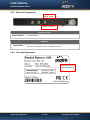
11.1.4 Mobile Internet Connection
The Mobile Internet Connection method is suitable for USB modem mobile connection such as 3G,
WiMAX, LTE, EVDO, EDGE, and GPRS, etc. Currently it only applies to USB mobile WAN port. For the
list of supported modems, please refer to Peplink Modem Support page: http://www.peplink.com/modem
Connection Settings for Mobile Internet Connection
Enable
Toggle the radio button to Yes to enable the connection.
This setting specifies the utilization of the WAN connection.
Connection
Type
The selection of Always-on results in the WAN connection to be used whenever it is available. If
Backup is selected, the WAN connection is treated as a backup connection and is used only in
the absence of available Always-on WAN.
The default and recommended Connection Type is Always-on.
This option allows you to choose whether to remain the connection connected or disconnect
when this WAN connection is no longer in the highest priority and has entered the standby state.
Standby State
When Remain connected is chosen, upon bringing up this WAN connection to active, it will be
immediately available for use.
Idle
Disconnect
With this option enabled, an idle connection will be disconnected after a specified minutes of
time. This time value specified is global and will affect all WAN profiles. The mobile connection
will re-establish on demand.
Reply to ICMP If this field is disabled, the WAN connection will not respond to ICMP Ping requests.
Ping
By default, this is enabled.
Operator
Settings
This setting applies to 3G / LTE / EDGE / GPRS modem only. It does not apply to EVDO / EVDO
Rev. A modem.
This allows you to configure the APN settings of your connection. If Auto is selected, Peplink
Balance will automatically detect the APN, configure the modem, and make connection. You may
change the APN settings by selecting Custom Mobile Operator Settings.
http://www.peplink.com
-54 / 193 -
Copyright © 2012 Peplink
USER MANUAL
Peplink Balance Series
The default and recommended Operator Settings is Auto.
The correct values can be obtained from your mobile Internet service provider.
SIM PIN
(Optional)
This is an optional field which is only needed when there is SIM lock for your SIM card service.
Each ISP may provide a set of DNS servers for DNS lookups. This field specifies the DNS
Servers to be used when a DNS lookup is routed through this connection.
DNS Servers
You can input the ISP provided DNS server addresses into the DNS server 1 and DNS server 2
fields. If no address is entered here, this link will not be used for DNS lookups.
This option is enabled automatically and it is required to define the DNS server when GRE is
enabled.
Please refer to Section 11.3, 11.4, 11.5, and 11.6 for details about WAN Health Check, Bandwidth
Allowance Monitor, Additional Public IP Settings, and Dynamic DNS Settings respectively.
http://www.peplink.com
-55 / 193 -
Copyright © 2012 Peplink
USER MANUAL
Peplink Balance Series
11.1.4.1
Modem Specific Custom Settings
The following settings may be available depending on the modem model. The example below is for a 3G
modem.
Modem Specific Custom Settings
Modem Model
This field displays the Manufacturer name of the connected mobile modem.
IMSI
This field shows the IMSI number associated with the SIM inside the mobile modem.
Network Type
This setting allows you to define your preference of using the 3G and/or 2G networks.
3G networks include HSPA / UMTS; 2G networks include EDGE / GPRS.
If 3G only or 2G only is chosen, only the HSPA / UMTS or EDGE / GPRS network will
be used, respectively. If the chosen network is not available, no other network will be
used regardless of its availability. The modem connection will remain offline.
If 3G preferred or 2G preferred is chosen, the chosen network will be used when it is
available. If the chosen network is not available, the other network will be used
whenever available.
The default Network Type is 3G preferred.
GSM Frequency
Band
This setting allows you to specify which GSM frequency band to be used.
GSM1900 is used in United States, Canada, and many other countries in the Americas.
GSM900 / GSM1800 / GSM2100 are used in Europe, Middle East, Africa, Asia,
Oceania, and Brazil.
If All Bands is chosen, the appropriate frequency band will be used automatically.
The default GSM Frequency Band is All Bands.
http://www.peplink.com
-56 / 193 -
Copyright © 2012 Peplink
USER MANUAL
Peplink Balance Series
11.1.4.2
WiMAX Settings
If a WiMAX modem is present in the system, its settings user interface can be accessed at: Network >
Interfaces > WAN > Mobile Internet
The example shown here relates to Sprint’s WiMAX modems 250U or 600U.
Modem Specific Custom Settings
Modem Model
ESN
Network Type
The brand of the Modem is automatically detected and appears here.
The modem's electronic serial number (ESN) is also auto-detected and appears here.
This is to specify the Network type e.g. 3G or 4G, to be used with the modem.
11.2 Physical Interface Settings
Physical Interface Settings
Speed
This setting specifies port speed and duplex configurations of the WAN Port.
By default, Auto is selected and the appropriate data speed is automatically detected by
Peplink Balance.
In the event of negotiation issues, the port speed can be manually specified to circumvent
the issues. You can also choose whether or not to advertise the speed to the peer by
selecting the Advertise Speed checkbox.
MTU
This setting specifies the Maximum Transmission Unit.
By default, MTU is set to Custom 1440.
You may adjust the MTU value by editing the text field. Click Default to restore the default
MTU value. Select Auto and the appropriate MTU value will be automatically detected. The
auto-detection will run each time when the WAN connection establishes.
http://www.peplink.com
-57 / 193 -
Copyright © 2012 Peplink
USER MANUAL
Peplink Balance Series
MSS
This setting should be configured based on the maximum payload size that the local system
can handle. The MSS (Maximum Segment Size) is computed from the MTU minus 40
bytes for TCP over IPv4.
If MTU is set to Auto, the MSS will also be set automatically.
By default, MSS is set to Auto.
MAC
Address
Clone
This setting allows you to configure the MAC address.
Some service providers (e.g. cable providers) identify the client’s MAC address and require
the client to always use the same MAC address to connect to the network. In such cases,
change the WAN interface’s MAC address to the original client PC’s one via this field.
The default MAC Address is a unique value assigned at the factory. In most cases, the
default value is sufficient. Clicking the Default button restores the MAC Address to the
default value.
VLAN
Some service providers require the router to enable VLAN tagging for Internet traffic. If it is
required by your service provider, you can enable this field and enter the VLAN ID that the
provider requires.
Note: Leave this field disabled if you are not sure.
http://www.peplink.com
-58 / 193 -
Copyright © 2012 Peplink
USER MANUAL
Peplink Balance Series
11.3 WAN Health Check
To ensure traffic is routed to healthy WAN connections only, Peplink Balance provides the functionality to
periodically check the health of each WAN connection.
The Health Check settings for each WAN connection can be independently configured via Network >
Interfaces > WAN > Health Check Settings
Enable the Health Check Settings by drop down to PING, DNS Lookup or HTTP
Health Check Settings
Method
This setting specifies the health check method for the WAN connection. The value of
Method can be configured as Disabled, Ping or DNS Lookup. The default method is DNS
Lookup. For Mobile Internet connection, the value of Method can be configured as
Disabled or SmartCheck.
Health Check Disabled
When Disabled is chosen in the Method field, the WAN connection will always be considered as up. The
connection will NOT be treated as down in the event of IP routing errors.
Health Check Method: Ping
The ICMP PING packets will be issued to test the connectivity with a configurable target IP address or host name.
A WAN connection is considered as up if PING responses are received from either one or both of the PING Hosts.
PING Hosts
This setting specifies IP addresses or host names with which connectivity is to be tested via
ICMP Ping.
If Use first two DNS servers as Ping Hosts is checked, the target PING Host will be the
first DNS server for the corresponding WAN connection.
Reliable PING hosts with a high uptime should be considered.
By default, the first two DNS servers of the WAN connection are used as the PING Hosts.
Health Check Method: DNS Lookup
http://www.peplink.com
-59 / 193 -
Copyright © 2012 Peplink
USER MANUAL
Peplink Balance Series
DNS lookups will be issued to test the connectivity with target DNS servers. The connection will be treated as up if
DNS responses are received from either one or both of the servers, regardless of whether the result was positive or
negative.
This field allows you to specify two DNS hosts’ IP address with which connectivity is to be
tested via DNS Lookup.
If Use first two DNS servers as Health Check DNS Servers is checked, the first two DNS
servers will be the DNS lookup targets for checking a connection's health. If the box is not
checked, field Host 1 must be filled and field Host 2 is optional.
Health Check DNS If the box Include public DNS servers is selected and no response is received from all
specified DNS servers, DNS lookups will also be issued to some public DNS servers. A
Servers
WAN connection will be treated as down only if there is also no response received from the
public DNS servers.
Connections will be considered up if DNS responses are received from any one of the
health check DNS servers, regardless of a positive or negative result.
By default, the first two DNS servers of the WAN connection are used as the Health Check
DNS Servers.
Health Check Method: HTTP
HTTP connections will be issued to test the connectivity with configurable URLs and strings to match.
URL 1
URL 2
WAN Settings > WAN Edit > Health Check Settings > URL 1
The URL will be retrieved when performing an HTTP health check. When String to Match is
left blank, a health check will pass if the HTTP return code is between 200 and 299 (Note:
HTTP redirection codes 301 or 302 are treated as failures). When String to Match is filled, a
health check will pass if the HTTP return code is between 200 and 299 and if the HTTP
response content contains the string.
WAN Settings > WAN Edit > Health Check Settings > URL 2
If URL 2 is also provided, a health check will pass if either one of the tests passed.
http://www.peplink.com
-60 / 193 -
Copyright © 2012 Peplink
USER MANUAL
Peplink Balance Series
Other Health Check Settings
This setting specifies the timeout, in seconds, for ping/DNS lookup requests. Default
Timeout is set to 5 seconds.
Timeout
Health Check
Interval
This setting specifies the time interval, in seconds, between ping or DNS lookup requests.
Default Health Check Interval is 5 seconds.
Health Check
Retries
This setting specifies the number of consecutive ping/DNS lookup timeouts after which
Peplink Balance is to treat the corresponding WAN connection as down. Default Health
Retries is set to 3.
For example, with the default Health Retries setting of 3, after consecutive 3 timeouts, the
corresponding WAN connection will be treated as down.
Recovery Retries
This setting specifies the number of consecutive successful ping/DNS lookup responses
that must be received before Peplink Balance treats a previously down WAN connection to
be up again.
By default, Recover Times is set to 3. For example, a WAN connection that is treated as
down will be considered to be up again upon receiving 3 consecutive successful ping/DNS
lookup responses.
Note
In case a WAN connection goes down, all of the WAN connections with non-Always-on Connection Type will also
be brought up until any one of higher priority WAN connections is up and found to be healthy. This design could
increase the overall network availability.
For example, if WAN1, WAN2 and WAN3 have the connection types of Always-on, Backup Priority Group 1 and
Backup Priority Group 2 respectively, when WAN1 goes down, WAN2 and WAN3 will also try to connect. If WAN3 is
connected first, WAN2 will still be kept connecting. If WAN2 is connected, WAN3 will disconnect or abort making
connection.
Automatic Public DNS Server Check on DNS Test Failure
In case the health check method is set to DNS Lookup and checks failed, the Balance will automatically perform
DNS lookups on some public DNS servers. If the tests are success, it means the WAN may not be down but rather
the target DNS server became malfunctioned. You will see the following warning message on the Main page.
http://www.peplink.com
-61 / 193 -
Copyright © 2012 Peplink
USER MANUAL
Peplink Balance Series
11.4 Bandwidth Allowance Monitor
Bandwidth Allowance Monitor helps keep track of your network usage. Please refer to section 23.8 to
view the usage statistics.
Bandwidth Allowance Monitor
If the feature Email Notification is enabled, you will be notified through email when usage
hits 75% and 95% of the monthly allowance.
Action
Start Day
Monthly Allowance
If the box Disconnect when usage hits 100% of monthly allowance is checked, this
WAN connection will be disconnected automatically when the usage hits the monthly
allowance. It will not resume connection unless this option has been turned off or the usage
has been reset when a new billing cycle starts.
This option allows you to define which day in the month each billing cycle begins.
This field is for defining the maximum bandwidth usage allowed for the WAN connection
each month.
Disclaimer
Due to different network protocol overheads and conversions, the amount of data as reported by this Peplink device
is not representative of actual billable data usage as metered by your network provider. Peplink disclaims any
obligation or responsibility for any events arising out of the use of the numbers shown here.
http://www.peplink.com
-62 / 193 -
Copyright © 2012 Peplink
USER MANUAL
Peplink Balance Series
11.5 Additional Public IP Settings
Additional Public IP Settings
IP Address List
The IP Address List represents the list of fixed Internet IP addresses assigned by the ISP, in
the event that more than one Internet IP addresses are assigned to this WAN connection.
Enter the fixed Internet IP addresses and the corresponding subnet mask, and then click the
Down Arrow button to populate IP address entries to the IP Address List.
http://www.peplink.com
-63 / 193 -
Copyright © 2012 Peplink
USER MANUAL
Peplink Balance Series
11.6 Dynamic DNS Settings
Peplink Balance provides the functionality to register the domain name relationships to dynamic DNS
service providers. Through registration with dynamic DNS service provider(s), the default public Internet
IP address of each WAN connection can be associated with a host name. With Dynamic DNS service
enabled for a WAN connection, you can connect to your WAN's IP address from the external even if its IP
address is dynamic. You have to register for an account from the listed dynamic DNS service providers
before enabling this option.
If the WAN connection's IP address is a reserved private IP address (i.e. behind a NAT router), the Public
IP of each WAN will be automatically reported to the DNS service provider.
Either upon a change in IP addresses or every 23 days without link reconnection, Peplink Balance will
connect to the dynamic DNS service provider to perform an IP address update within the provider’s
records.
The settings for dynamic DNS service provider(s) and the association of host name(s) are configured via
Network > Interfaces > WAN Settings > Dynamic DNS Settings
If your desired provider is not listed, you may check with DNS-O-Matic. This service supports updating 30
other dynamic DNS service providers.
(Note: Peplink is not affiliated with DNS-O-Matic)
Dynamic DNS Settings
This setting specifies the dynamic DNS service provider to be used for the WAN based
on supported dynamic DNS service providers:
Service Provider
changeip.com
dyndns.org
no-ip.org
tzo.com
DNS-O-Matic
Select Disabled to disable this feature.
User ID / User / Email
http://www.peplink.com
This setting specifies the registered user name for the dynamic DNS service.
-64 / 193 -
Copyright © 2012 Peplink
USER MANUAL
Peplink Balance Series
Password / Pass / TZO
This setting specifies the password for the dynamic DNS service.
Key
Hosts / Domain
This setting specifies a list of hostnames or domains to be associated with the public
Internet IP address of the WAN connection.
Important Note
In order to use dynamic DNS services, appropriate hostname registration(s), as well as a valid account with a
supported dynamic DNS service provider are required.
A dynamic DNS update is performed whenever a WAN’s IP address changed, e.g. IP is changed after a DHCP IP
refresh, reconnection, etc.
Due to dynamic DNS service providers’ policy a dynamic DNS host would expire automatically because the host
record was not updated for a long time. Therefore Peplink Balance performs an update every 23 days even if a
WAN’s IP address did not change.
12
Bandwidth Bonding SpeedFusionTM
(Available on Peplink Balance 210+)
Peplink Balance Bandwidth Bonding SpeedFusionTM functionality securely connects one or more branch
offices to your company's main headquarters or to other branches. The data, voice, or video
communications between these locations are kept confidential across the public Internet.
The Bandwidth Bonding SpeedFusionTM of the Peplink Balance is specifically designed for multi-WAN
environment. The Peplink Balance can bond all WAN connections’ bandwidth for routing SpeedFusionTM
traffic. Unless all the WAN connections of one site are down, the Peplink Balance can still maintain VPN
up and running. Bandwidth Bonding is enabled by default.
http://www.peplink.com
-65 / 193 -
Copyright © 2012 Peplink
USER MANUAL
Peplink Balance Series
12.1 SpeedFusionTM Settings
TM
Peplink Balance 380, 580, 710 and 1350 support making multiple SpeedFusion connections with a
remote Peplink Balance 210, 310, 380, 580, 710, 1350, or a Pepwave MAX Mobile Router. Peplink
Balance 210 and 310 support making two SpeedFusionTM connections with a remote Peplink Balance
210, 310, 380, 580, 710, 1350, or a Pepwave MAX Mobile Router.
Peplink Balance that supports multiple VPN connections can act as a central hub which connects branch
offices. For example, branch office A and branch office B make VPN connections to headquarters C, both
branch offices’ LAN subnet and subnets behind it (i.e. static routes) will also be advertised to the
headquarters C and the other branches. So branch office A will be able to access branch office B via
headquarters C in this case.
The local LAN subnet and subnets behind the LAN (defined under Static Route in the LAN settings page)
will be advertised to the VPN. All VPN members (branch offices and headquarters) will be able to route to
the local subnets.
Note that all LAN subnet and subnets behind it have to be unique. Otherwise, VPN members will not be
able to access each other.
All data can be routed over the VPN with 256-bit AES encryption standard.
To configure, navigate to Network > SpeedFusionTM
TM
To configure, navigate to Network > SpeedFusion
> New Profile
This will open a page similar to the one as shown below
http://www.peplink.com
-66 / 193 -
Copyright © 2012 Peplink
USER MANUAL
Peplink Balance Series
A list of defined SpeedFusionTM Connection profiles and Link Failure Detection Time option will be
shown. Click the New Profile button to create a new VPN connection profile for making VPN connection
to a remote Peplink Balance via the available WAN connections. Each profile is for making VPN
connection with one remote Peplink Balance
VPN Settings
VPN
Connection
Name
This field is for specifying a name to represent this profile. The name can be any
combination of alphanumeric characters (0-9, A-Z, a-z), underscore (_), dash (-), and/or
non-leading/trailing spaces ( ).
Active
When this box is checked, this VPN connection profile will be enabled. Otherwise, it will be
disabled.
Encryption
By default, VPN traffic is encrypted with 256-bit AES standard. If the option Off is selected
on both sides of a VPN connection, no encryption will be applied.
Peer Serial
Number
Pre-shared Key
Peplink Balance only establishes VPN connection with a remote peer that has a serial
number specified here. If the remote peer is in high availability setup, you can check the
box “Remote client is set up in high availability mode” and enter the second unit's serial
number into the second text box.
This is an optional field which defines the pre-shared key used for this particular VPN
connection. The VPN connection's session key will be further protected by the factor of the
pre-shared key. The connection will be up only if the pre-shared keys on each side match.
When the peer is running firmware 5.0 or 5.1, this setting will be ignored.
Peer IP Addresses Enter the remote peer’s WAN IP address(es) or host name(s) here. Dynamic-DNS host
/ Host Names
names are accepted.
(Optional)
This field is optional. With this field filled, the Peplink Balance will initiate connection to each
http://www.peplink.com
-67 / 193 -
Copyright © 2012 Peplink
USER MANUAL
Peplink Balance Series
of the remote IP addresses until success. If the field is empty, the Peplink Balance will wait
for connection from the remote peer. Therefore, at least one side of the two VPN peers has
to have this field filled. Otherwise, VPN connection cannot be established.
Enter one IP address or host name per line.
When this check box is unchecked, traffic between local and remote networks will be IP
forwarded.
Layer 2 Bridging
To bridge the Ethernet network of an Ethernet port on a local and remote network, select
this check box. When this check box is selected, the two networks will become a single
LAN, and any broadcast (e.g., ARP requests) or multicast traffic (e.g., Bonjour) will be sent
over the VPN.
This field specifies the port to be bridged to the remote site.
Bridge Port
VLAN Tagging
STP
Preserve LAN
Settings Upon
Connected
If you choose WAN Port that WAN will be disabled for WAN purposes. Instead, the WAN
port will be dedicated to bridging with the remote site. The LAN port will remain unchanged.
This field specifies the VLAN ID with which the VPN's traffic should be tagged before
sending the traffic to the bridge port. If no VLAN tagging is needed, select No VLAN. To
define a new VLAN ID, click New... and input the VLAN ID. VLAN IDs that are not
referenced by any VPN profiles will be removed from the list automatically. Default: No
VLAN
Checking this box enables Spanning Tree Protocol.
Default: Unchecked.
The LAN port is chosen as the bridge port. Selecting this option preserves LAN settings
(e.g., LAN port IP address, DHCP server, etc.) when the Layer 2 VPN is connected.
Uncheck this option if the LAN IP address and gateway will use remote LAN settings.
Check this option if the LAN IP address and local DHCP server should remain unchanged
after the VPN is up.
If you choose not to preserve LAN settings when the VPN is connected, the device will not
act as a router, and most Layer 3 routing functions will cease to work.
WAN Connection Priority
WAN Connection
Priority
You can specify the priority of the WAN connections to be used in making VPN bonding
connections. A Wan connection will never be used when OFF is selected. Only available
WAN connections with the highest priority will be utilized.
Link Failure Detection
Link Failure
Detection Time
The bonded VPN can detect routing failures on the path between two sites over each WAN
connection. Failed WAN connections will not be used to route VPN traffic. Health check
packets are sent to the remote unit to detect any failure. The more frequent checks it sends,
the shorter detection time, but the higher bandwidth overhead will be consumed.
When Recommended is selected, a health check packet is sent out every 5 seconds, and
the expected detection time is 15 seconds.
http://www.peplink.com
-68 / 193 -
Copyright © 2012 Peplink
USER MANUAL
Peplink Balance Series
When Fast is selected, a health check packet is sent out every 3 seconds, and the
expected detection time is 6 seconds.
When Faster is selected, a health check packet is sent out every 1 second, and the
expected detection time is 2 seconds.
When Extreme is selected, a health check packet is sent out every 0.1 second, and the
expected detection time is under 1 second.
By default, Recommended is selected.
Important Note to Users Upgrading to Firmware 5.4
The Bandwidth Bonding SpeedFusionTM in firmware 5.4 recommends the same firmware version for all devices in
the VPN network. The feature is backwards compatible with firmware version 5.3 & 5.2.
Important Note
TM
Peplink proprietary SpeedFusion used TCP port 32015 and UDP port 4500 for establishing VPN connections. If
you have a firewall in front of the Peplink Balance devices, you will need to add firewall rules for these port and
protocols which will allow inbound and outbound traffic pass-through the firewall.
Tip
Watch a video walkthrough of setting up a SpeedFusionTM on our YouTube Channel for a video tutorial!
http://youtu.be/xNaq13FWu_g
http://www.peplink.com
-69 / 193 -
Copyright © 2012 Peplink
USER MANUAL
Peplink Balance Series
12.2 Peplink Balance Behind NAT Router
TM
The Peplink Balance supports establishing SpeedFusion over WAN connections which are behind a
NAT (Network Address Translation) router.
To be able for a WAN connection behind a NAT router to accept VPN connections, you can configure the
NAT router in front of the WAN connection to inbound port forward TCP port 32015 to the Peplink
Balance.
If one or more WAN connections on Unit A can accept VPN connections (by means of port forwarding or
not) while none of the WAN connections on the peer Unit B can do so, you should put all public IP
addresses or host names of the Unit A to the Unit B’s Remote IP Addresses / Host Names field. Leave
the field in Unit A blank. With such setting, SpeedFusionTM connection can be set up and all WAN
connections on both sides will be utilized.
For example, see the following diagram:
One of the WANs of Balance A is non-NAT’d (212.1.1.1). The rest of the WANs on Balance A and all
WANs on Balance B are NAT’d. In such case, the Peer IP Addresses / Host Names field in Balance B
should be filled with all of the Balance A’s host names or public IP addresses (i.e. 212.1.1.1, 212.2.2.2
and 212.3.3.3), and the field in Balance A can be left blank. The two NAT routers on WAN1 and WAN3 of
Balance A should inbound port forward TCP port 32015 to the Balance A so that all WANs would be
utilized to establish VPN.
http://www.peplink.com
-70 / 193 -
Copyright © 2012 Peplink
USER MANUAL
Peplink Balance Series
12.3 SpeedFusionTM Status
SpeedFusionTM Status is shown in the Dashboard. The connection status of each connection profile is
shown as below.
SpeedFusionTM connection status is also shown on the LCD panel of Peplink Balance 380, 580, 710 and
1350.
By clicking the Details button at the top-right hand corner of SpeedFusionTM table, you will be forwarded
TM
to Status > SpeedFusion . You can view the subnet and WAN connection information of each VPN
peer. Please refer to section 23.6 for details.
IP subnets must be unique among VPN peers
The entire inter-connected SpeedFusionTM network is one single non-NAT IP network. No two subnets in two sites
shall be duplicated. Otherwise, connectivity problems will be experienced in accessing those subnets.
http://www.peplink.com
-71 / 193 -
Copyright © 2012 Peplink
USER MANUAL
Peplink Balance Series
13
IPsec VPN
Peplink Balance IPsec VPN functionality securely connects one or more branch offices to your company's
main headquarters or to other branches. The data, voice, or video communications between these
locations are thus kept safe and confidential across the public Internet.
The IPsec VPN of the Peplink Balance is especially designed for a multi-WAN environment. For instance,
a user sets up multiple IPsec profiles for his multi- WAN1 ~ WAN3 environment, if WAN1 is connected
and its health check turns up good, the IPsec traffic will go through this link. However, should unforeseen
problems (e.g. physically unplugged or ISP problems) arise and cause WAN1 to go down, our IPsec
implementation will make use of WAN2 and WAN3 accordingly, as failover purposes.
13.1 IPsec VPN Settings
All of our Peplink products can make multiple IPsec VPN connections with Peplink as well as Cisco or
Juniper Routers.
Note that all LAN subnet and subnets behind it have to be unique. Otherwise, VPN members will not be
able to access each other.
All data can be routed over the VPN with a selection of encryption standards such as 3DES, AES-128
and AES-256.
To configure, navigate to Network > IPsec VPN:
A NAT-Traversal option and list of defined IPsec VPN profiles will be shown.
The NAT-Traversal option should be enabled if your system is behind a NAT router.
Click the New Connection button to create new IPsec VPN profiles that make VPN connections to
remote Peplink Balance, Cisco or Juniper Routers via the available WAN connections. To edit any of the
profiles, click on its associated connection name in the leftmost column.
http://www.peplink.com
-72 / 193 -
Copyright © 2012 Peplink
USER MANUAL
Peplink Balance Series
IPsec VPN Settings
Name
This field is for specifying a local name to represent this connection profile.
Active
When this box is checked, this IPsec VPN connection profile will be enabled. Otherwise, it
will be disabled.
Remote
Gateway IP
Address
Local Networks
Enter the remote peer’s public IP address. For Aggressive Mode, this is optional..
Enter the local LAN subnets here. If you have defined “static routes”, they will be shown
here too.
http://www.peplink.com
-73 / 193 -
Copyright © 2012 Peplink
USER MANUAL
Peplink Balance Series
Remote
Networks
Enter the LAN and subnets that are located at the remote site here.
Main Mode
Choose this Main Mode if both IPsec peers use static IP addresses.
Aggressive
Mode
Choose this Aggressive Mode if one of the IPsec peers use dynamic IP addresses.
Force UDP
For UDP encapsulation to be forced regardless of the NAT-Traversal, tick this checkbox.
Encapsulation
Pre-shared Key
This defines the peer authentication pre-shared key to be used to authenticate this VPN
connection. The connection will be up only if the pre-shared keys on each side match.
Under Main Mode, this field can be left blank.
Local ID
Under Aggressive Mode, if Remote Gateway IP Address field is filled on this end and the
peer end, this field can be left blank. Otherwise, this field is typically a U-FQDN.
Under Main Mode, this field can be left blank.
Remote ID
Phase 1 (IKE)
Proposal
Phase 1 DH
Group
Under Aggressive Mode, if Remote Gateway IP Address field is filled on this end and the
peer end, this field can be left blank. Otherwise, this field is typically a U-FQDN.
Under Main Mode, this allows the setting of up to 6 encryption standards, in descending
order of priority, to be used in the initial connection key negotiations.
For Aggressive Mode, only one selection is permitted.
This is the Diffie-Hellman group used within IKE. This allows two parties to establish a
shared secret over an insecure communications channel. The larger the group number, the
higher the security.
Group 2 - 1024-bit is the default value.
Group 5 - 1536-bit is the alternative option.
Phase 1 SA
Lifetime
Phase 2 (ESP)
Proposal
This setting specifies the lifetime limit of this Phase 1 Security Association. By default, it is
set at 3600 seconds.
Under Main Mode, this allows the setting of up to 6 encryption standards, in descending
order of priority, to be used for the IP data that is being transferred.
For Aggressive Mode, only one selection is permitted.
The Perfect Forward Secrecy (PFS) ensures that if a key was compromised, the attacker
will be able to access only the data protected by that key but not any other data.
Phase 2 PFS
Group
None - Do not request for PFS when initiating connection. However, since there is no valid
reason to refuse PFS, the system will allow the connection to use PFS if requested by the
remote peer. This is the default value.
Group 2 - 1024-bit Diffie-Hellman group. The larger the group number, the higher the
security.
Group 5 - 1536-bit is the third option.
Phase 2 SA
Lifetime
This setting specifies the lifetime limit of this Phase 2 Security Association. By default, it is
set at 28800 seconds.
http://www.peplink.com
-74 / 193 -
Copyright © 2012 Peplink
USER MANUAL
Peplink Balance Series
13.2 IPsec Status
IPsec Status shows the current connection status of each connection profile and is displayed in Status >
IPsec.
14
Management of Outbound Traffic to WAN
Peplink Balance provides the functionality to flexibly manage and load balance outbound traffic among
the WAN connections.
1. Important Note
Outbound Policy is applied only when more than one WAN connection is active.
The settings for managing and load balancing outbound traffic are located in
Network > Outbound Policy:
The outbound policy for managing and load balancing outbound traffic policy are located at
Network > Outbound Policy > Click on
14.1 Outbound Policy
There are three main selections for the Outbound Traffic Policy of Peplink Balance:
High Application Compatibility
Normal Application Compatibility
Custom
http://www.peplink.com
-75 / 193 -
Copyright © 2012 Peplink
USER MANUAL
Peplink Balance Series
The selections are explained as follows:
Outbound Policy Settings
High Application
Compatibility
With the selection of this policy, outbound traffic from a source LAN device is routed
through the same WAN connection regardless of the destination Internet IP address and
protocol.
This provides the highest application compatibility.
Normal
Application
Compatibility
Custom
With the selection of this policy, outbound traffic from a source LAN device to the same
destination Internet IP address will persistently be routed through the same WAN
connection regardless of protocol.
This provides high compatibility to most applications, and users still benefit from WAN link
load balancing when multiple Internet servers are accessed.
With the selection of this policy, outbound traffic behavior can be managed by defining
custom rules.
Rules can be defined in a custom rule table. A default rule can be defined for connections
that cannot be matched with any one of the rules.
The default policy is Normal Application Compatibility.
Tip
Want to know more about how-to create outbound rules? Visit our YouTube Channel for a video tutorial!
http://youtu.be/rKH4AS_bQnE
http://www.peplink.com
-76 / 193 -
Copyright © 2012 Peplink
USER MANUAL
Peplink Balance Series
14.2 Custom Rules for Outbound Policy
Click
in the Outbound Policy form. Choose Custom and press the Save button. The following
screen will then be displayed.
The bottom-most rule is Default. Edit this rule to change the device’s default way to control outbound
traffic for all connections that does not match any rules above it. Click on the service name Default to
change its settings.
You may drag and drop a row to rearrange the priority of outbound rules.
By default, Auto is selected for the option Default Rule. You can select Custom in order to change the
Algorithm to be used. Please refer to the upcoming sections for the details of the available algorithms.
To create a custom rule, click Add Rule at the bottom of the table, and the following window will be
displayed:
http://www.peplink.com
-77 / 193 -
Copyright © 2012 Peplink
USER MANUAL
Peplink Balance Series
New Custom Rule Settings
Service Name
This setting specifies the name of the outbound traffic rule.
This setting specifies whether the outbound traffic rule takes effect.
Enable
With an Enable value of Yes, the rule takes effect: traffic is matched, and actions are
taken,by Peplink Balance based on the other parameters of the rule.
With an Enable value of No, the rule does not take effect: Peplink Balance disregards the
other parameters of the rule.
Source
This setting specifies the source IP Address, IP Network or MAC Address for traffic that
matches the rule.
This setting specifies the destination IP Address or IP Network or Domain Name for traffic
that matches the rule.
Destination
If Domain Name is chosen and a domain name, such as foobar.com, is entered, any
outgoing accesses to foobar.com and *.foobar.com will match this criterion. You may enter
a wildcard (.*) at the end of a domain name to match any host with a name having the
domain name in the middle. If you enter foobar.*, for example, then www.foobar.com,
www.foobar.co.jp, or foobar.co.uk will also match. Placing wildcards in any other position is
not supported.
NOTE: if a server has one Internet IP address and multiple server names, and if one of the
names is defined here, then accesses to any one of the server names will also match this
rule.
Protocol and Port
This setting specifies the IP Protocol and Port of traffic that matches this rule. You may
select some common protocol from the Protocol Selection Tool drop-down menu.
This setting specifies the behavior of Peplink Balance for the custom rule.
One of the following values can be selected:
Algorithm
Weighted Balance
Persistence
Enforced
Priority
Overflow
Least Used (not applicable to Balance 20/30)
Lowest Latency (not applicable to Balance 20/30)
The upcoming sections present the details of the listed algorithms.
This setting specifies whether to terminate existing IP sessions on a less preferred WAN
connection in the event that a more preferred WAN connection is recovered. This setting is
applicable to the Algorithms: Weighted, Persistence and Priority.
Terminate Sessions
on Link Recovery By default, this is disabled. In this case, all existing IP sessions will not be terminated or
affected when any other WAN connection is recovered. If it is set to enabled, existing IP
sessions may be terminated when another WAN connection is recovered such that only the
preferred healthy WAN connection(s) are used at any point in time.
http://www.peplink.com
-78 / 193 -
Copyright © 2012 Peplink
USER MANUAL
Peplink Balance Series
14.2.1 Algorithm: Weighted Balance
This setting specifies the ratio of WAN connection usage to be applied on the specified IP Protocol & Port,
and is applicable only when Algorithm is set to Weighted Balance.
The amount of matching traffic that is distributed to a WAN connection is proportional to the weight of
WAN connection relative to the total weight. Use the sliders to change each WAN’s weight.
Example: With the following weight settings on a Peplink Balance 310:
WAN1: 10
WAN2: 10
WAN3: 5
Total weight is 25 = (10 + 10 + 5)
Matching traffic distributed to WAN1 is 40% = (10 / 25) x 100%
Matching traffic distributed to WAN2 is 40% = (10 / 25) x 100%
Matching traffic distributed to WAN3 is 20% = (5 / 25) x 100%
14.2.2 Algorithm: Persistence
The configuration of Persistent Services is the solution to the few situations where link load distribution for
Internet services is undesirable.
For example, many e-banking and other secure websites, for security reasons, terminate the session
when the client computer’s Internet IP address changes mid-session.
In general, different Internet IP addresses represent different computers. The security concern is that an
IP address change during a session may be the result of an unauthorized intrusion attempt. Therefore, to
prevent damages from the potential intrusion, the session is terminated upon the detection of an IP
address change.
Peplink Balance can be configured to distribute data traffic across multiple WAN connections. Also, the
Internet IP depends on the WAN connections over which communication actually takes place. As a result,
a LAN client computer behind Peplink Balance may communicate using multiple Internet IP addresses.
For example, a LAN client computer behind a Peplink Balance 310 with three WAN connections may
communicate on the Internet using three different IP addresses.
With the Persistency feature of Peplink Balance, rules can be configured to enable client computers to
persistently utilize the same WAN connections for e-banking and other secure websites. As a result, a
client computer will communicate using one IP address and eliminate the issues.
There are two Persistent Modes. One is by source and the other by destination.
http://www.peplink.com
-79 / 193 -
Copyright © 2012 Peplink
USER MANUAL
Peplink Balance Series
By Source:
By Destination:
The same WAN connection will be used for traffic matching the rule and originating from
the same machine regardless of its destination. This option will provide the highest level of
application compatibility.
The same WAN connection will be used for traffic matching the rule, originating from the
same machine, and going to the same destination. This option can better distribute load to
WAN connections when there are only a few client machines.
The default Mode is By Source.
When there are multiple client requests, they can be distributed (persistently) to WAN connections with a
weight. If you choose Auto in Load Distribution, the weights will be automatically adjusted according to
each WAN’s Download Bandwidth which is specified in the WAN settings page (see Section11
Configuration of WAN Interface(s)). If you choose Custom, you can customize the weight of each WAN
manually by using the sliders.
14.2.3 Algorithm: Enforced
This setting specifies the WAN connection usage to be applied on the specified IP Protocol & Port, and is
applicable only when the Algorithm is set to Enforced.
Matching traffic will be routed through the specified WAN connection regardless of health check status of
the WAN connection.
Starting from firmware 5.2, outbound traffic can be enforced to go through a specified SpeedFusionTM
connection. (Available on Peplink Balance 210+)
14.2.4 Algorithm: Priority
This setting specifies the priority of the WAN connections to be utilized to route the specified network
service. The highest priority WAN connection available will always be used for routing the specified type
of traffic. A lower priority WAN connection will be used only when all higher priority connections have
become unavailable.
Starting from firmware 5.2, outbound traffic can be prioritized to go through SpeedFusionTM connection(s).
By default, VPN connections are not included in the priority list. (Available on Peplink Balance 210+)
Tip
Configure multiple distribution rules to accommodate different kinds of services.
http://www.peplink.com
-80 / 193 -
Copyright © 2012 Peplink
USER MANUAL
Peplink Balance Series
14.2.5 Algorithm: Overflow
The traffic matching this rule will be routed through the healthy WAN connection that has the highest
priority and is not in full load. When this connection gets saturated, new sessions will be routed to the
next healthy WAN connection that is not in full load.
Drag and drop to specify the order of WAN connections to be used for routing traffic. Only the highest
priority healthy connection that is not in full load will be utilized.
14.2.6 Algorithm: Least Used
(Available on Peplink Balance 210+)
The traffic matching this rule will be routed through the healthy WAN connection that is selected in the
field Connection and has the most available download bandwidth. The available download bandwidth of
a WAN connection is calculated from the total download bandwidth specified in the WAN settings page
and the current download usage. The available bandwidth and WAN selection is determined every time
when an IP session is made.
14.2.7 Algorithm: Lowest Latency
(Available on Peplink Balance 210+)
The traffic matching this rule will be routed through the healthy WAN connection that is selected in the
field Connection and has the lowest latency. Latency checking packets are issued periodically to a nearby
router of each WAN connection to determine its latency value. The latency of a WAN is the packet round
trip time of the WAN connection. Additional network usage may be incurred as a result.
Tip
The round trip time of a “6M down /640k up ”link can be higher than that of a “2M down /2M up” link. It is because
the overall round trip time is lengthened by its slower upload bandwidth despite of its higher downlink speed.
Therefore this algorithm is good for two scenarios:
All WAN connections are symmetric; or
A latency sensitive application requires to be routed through the lowest latency WAN regardless the WAN’s
available bandwidth.
http://www.peplink.com
-81 / 193 -
Copyright © 2012 Peplink
USER MANUAL
Peplink Balance Series
14.2.8 Expert Mode
Expert Mode is available for advance users. To enable the feature, click on the help test balloon and click
the link turn on Expert Mode.
TM
Under Expert Mode, a new special rule - "SpeedFusion Routes" is displayed on the Custom Rules
TM
table. It represents all SpeedFusion routes learned from remote VPN peers. By default, this bar is on
the top of all custom rules. That means traffic for remote VPN subnets will be routed to its corresponding
VPN peer. You can create custom Priority or Enforced rules and move them above the bar to override
TM
the SpeedFusion Routes.
Upon disabling the Expert Mode, all rules above the bar will be removed.
http://www.peplink.com
-82 / 193 -
Copyright © 2012 Peplink
USER MANUAL
Peplink Balance Series
15
Inbound Access
Inbound Access is also known as inbound port address translation. On NAT WAN connection, all inbound
traffic to the server behind Peplink unit requires Inbound Access rules.
By the custom definition of servers and services for inbound access, Internet users can access the
servers behind Peplink Balance. Advanced configurations allow inbound access to be distributed among
multiple servers on the LAN.
Important Note
Inbound Access applies only to WAN connections that operate under NAT mode. For WAN connections that
operate under drop-in mode or IP forwarding, inbound traffic is forwarded to the LAN by default.
15.1 Definition of Port Forwarding
(Available on Peplink Balance 20/30)
Inbound Port Forwarding rules are defined at: Network > Inbound Access > Port Forwarding
To define a new service, click the Add Service button
appears:
upon which the following
Port Forwarding Settings
This setting specifies whether the Inbound Service takes effect.
Enable
With an Enable value of Yes, the inbound service takes effect: traffic is matched, and actions
are taken by Peplink Balance based on the other parameters of the rule.
With an Enable value of No, the inbound service does not take effect: Peplink Balance
disregards the other parameters of the rule.
Service Name
This setting identifies the service to the System Administrator.
Valid values for this setting consist only of alphanumeric and the underscore “_” characters.
http://www.peplink.com
-83 / 193 -
Copyright © 2012 Peplink
USER MANUAL
Peplink Balance Series
The IP Protocol setting, along with the Port setting, specifies the protocol of the service as TCP,
UDP, ICMP or IP.
Traffic that is received by Peplink Balance via the specified protocol at the specified port(s) is
forwarded to the LAN hosts specified by the Servers setting.
IP Protocol
(Please refer below for details on the Port and Servers settings.)
Alternatively, the Protocol Selection Tool drop-down menu can be used to automatically fill in
the Protocol and a single Port number of common Internet services (e.g. HTTP, HTTPS, etc.)
After selecting an item from the Protocol Selection Tool drop-down menu, the Protocol and
Port number remains manually modifiable.
The Port setting specifies the port(s) that correspond to the service, and can be configured to
behave in one of the following manners:
Any Port, Single Port, Port Range, Port Map and Range Mapping
Any Port: all traffic that is received by Peplink Balance via the specified protocol is forwarded to
the servers specified by the Servers setting.
For example, with IP Protocol set to TCP, and Port set to Any Port, all TCP traffic is forwarded
to the configured servers.
Single Port: traffic that is received by Peplink Balance via the specified protocol at the specified
port is forwarded via the same port to the servers specified by the Servers setting.
For example, with IP Protocol set to TCP, and Port set to Single Port and Service Port 80,
TCP traffic received on Port 80 is forwarded to the configured servers via Port 80.
Port
Port Range: traffic that is received by Peplink Balance via the specified protocol at the
specified port range is forwarded via the same respective ports to the LAN hosts specified by
the Servers setting.
For example, with IP Protocol set to TCP, and Port set to Port Range and Service Port 80-88,
TCP traffic received on ports 80 through 88 is forwarded to the configured servers via the
respective ports.
Port Mapping: traffic that is received by Peplink Balance via the specified protocol at the
specified port is forwarded via a different port to the servers specified by the Servers setting.
For example, with IP Protocol set to TCP, and Port set to Port Mapping, Service Port 80, and
Map to Port 88, TCP traffic on Port 80 is forwarded to the configured servers via Port 88.
(Please see below for details on the Servers setting.)
Range Mapping: traffic that is received by Peplink Balance via the specified protocol at the
specified port range is forwarded via a different port to the servers specified by the Servers
setting.
Inbound IP
Address(es)
Server IP
Address
This setting specifies the WAN connections and Internet IP address(es) from which the service
can be accessed.
This setting specifies the LAN IP address of the server that handles the requests for the
service.
http://www.peplink.com
-84 / 193 -
Copyright © 2012 Peplink
USER MANUAL
Peplink Balance Series
15.2 Definition of Servers on LAN
(Available on Peplink Balance 210+)
The settings to configure servers on the LAN are located at the following location: Network > Inbound
Access > Servers
Inbound connections from the Internet will be forwarded to the specified Inbound IP Address(es) base on
the protocol and port number .
When more than one server is defined, requests will be distributed to the servers in the weight ratio
specified for each server.
To define a new server, click Add Server, upon which the following screen appears:
Enter a valid server name, and its corresponding LAN IP address.
Upon clicking Save after entering required information, the following screen appears.
To define additional servers, click Add Server and repeat the above steps.
http://www.peplink.com
-85 / 193 -
Copyright © 2012 Peplink
USER MANUAL
Peplink Balance Series
15.3 Inbound Access Services
15.3.1 Definition of Services
Services are defined at: Network > Inbound Access > Services
Tip
At least one server must be defined before services can be added.
To define a new service, click the Add Service button, upon which the following appears:
Services Settings
This setting specifies whether the inbound service rule takes effect.
Enable
When Yes is selected, the inbound service rule takes effect. If the inbound traffic matches the
specified IP Protocol and Port, action will be taken by Peplink Balance based on the other
parameters of the rule.
When No is selected, the inbound service rule does not take effect. Peplink Balance will
disregard the other parameters of the rule.
Service Name
This setting identifies the service to the System Administrator.
Valid values for this setting consist only of alphanumeric and the underscore “_” characters.
The IP Protocol setting, along with the Port setting, specifies the protocol of the service as
TCP, UDP, ICMP or IP.
IP Protocol
Traffic that is received by Peplink Balance via the specified protocol at the specified port(s) is
forwarded to the LAN hosts specified by the Servers setting.
(Please see below for details on the Port and Servers settings.)
Alternatively, the Protocol Selection Tool drop-down menu can be used to automatically fill
in the Protocol and a single Port number of common Internet services (e.g. HTTP, HTTPS,
etc.).
http://www.peplink.com
-86 / 193 -
Copyright © 2012 Peplink
USER MANUAL
Peplink Balance Series
After selecting an item from the Protocol Selection Tool drop-down menu, the Protocol and
Port number remains manually modifiable.
The Port setting specifies the port(s) that correspond to the service, and can be configured to
behave in one of the following manners:
Any Port, Single Port, Port Range, Port Map and Range Mapping
Any Port: all traffic that is received by Peplink Balance via the specified protocol is forwarded
to the servers specified by the Servers setting.
For example, with IP Protocol set to TCP, and Port set to Any Port, all TCP traffic is
forwarded to the configured servers.
Single Port: traffic that is received by Peplink Balance via the specified protocol at the
specified port is forwarded via the same port to the servers specified by the Servers setting.
For example, with IP Protocol set to TCP, and Port set to Single Port and Service Port 80,
TCP traffic received on Port 80 is forwarded to the configured servers via Port 80.
Port
Port Range: traffic that is received by Peplink Balance via the specified protocol at the
specified port range is forwarded via the same respective ports to the LAN hosts specified by
the Servers setting.
For example, with IP Protocol set to TCP, and Port set to Port Range and Service Port 8088, TCP traffic received on ports 80 through 88 is forwarded to the configured servers via the
respective ports.
Port Mapping: traffic that is received by Peplink Balance via the specified protocol at the
specified port is forwarded via a different port to the servers specified by the Servers setting.
For example, with IP Protocol set to TCP, and Port set to Port Map, Service Port 80, and
Mapping to Port 88, TCP traffic on Port 80 is forwarded to the configured servers via Port 88.
(Please see below for details on the Servers setting.)
Range Mapping: traffic that is received by Peplink Balance via the specified protocol at the
specified port range is forwarded via a different port to the servers specified by the Servers
setting.
Inbound IP
Address(es)
This setting specifies the WAN connections and Internet IP address(es) from which the
service can be accessed.
This setting specifies the LAN servers that handle requests for the service, and the relative
weight values.
Included
Server(s)
The amount of traffic that is distributed to a server is proportional to the weight value assigned
to the server relative to the total weight.
Example:
With the following weight settings on a Peplink Balance:
demo_server_1: 10
demo_server_2: 5
The total weight is 15 = (10 + 5)
http://www.peplink.com
-87 / 193 -
Copyright © 2012 Peplink
USER MANUAL
Peplink Balance Series
Matching traffic distributed to demo_server_1:67% = (10 / 15) x 100%
Matching traffic distributed to demo_server_2:33% = (5 / 15) x 100%
15.3.2 UPNP / NAT-PMP SETTINGS
UPnP and NAT-PMP are network protocols which allow a computer on the LAN to automatically configure
the router to allow parties on the WAN to connect to itself. In this way, the process of inbound port
forwarding is automated.
When a computer creates a rule using these protocols, the specified TCP/UDP port of all WAN
connections' default IP address will be forwarded.
Check the corresponding box(es) to enable UPnP and/or NAT-PMP. Enable these features only if you
trust the computers on the LAN.
When the options are enabled, a table listing all the forwarded ports under these two protocols can be
found at Status > UPnP / NAT-PMP.
15.3.3 Definition of DNS Records
(Available on Peplink Balance 210+)
The built-in DNS Server functionality of Peplink Balance facilitates inbound load balancing. With the
presence of the functionality, NS/SOA DNS records for a domain name can be delegated to Internet IP
address(es) of Peplink Balance. Upon receiving a DNS query, Peplink Balance supports returning, as an
“A” record, the corresponding IP address for the domain name on the most appropriate healthy WAN
connection. It also supports acting as a generic DNS server for hosting “A”, “CNAME”, “MX”, “TXT” and
“NS” records.
For example:
(This example is for illustration only; the actual resolution that takes place in implementation will likely be
different.)
The DNS resolution of the domain name www.mycompany.com is delegated to the WAN2 Internet IP
addresses of Peplink Balance.
Upon receiving the DNS query, Peplink Balance returns, as an “A” record, the IP address for
www.mycompany.com on WAN1 because WAN1 is the most appropriate healthy link.
The settings for defining the DNS records to be hosted by Peplink Balance are located at: Network>
Inbound Access > DNS Settings
http://www.peplink.com
-88 / 193 -
Copyright © 2012 Peplink
USER MANUAL
Peplink Balance Series
DNS Settings
This setting specifies the WAN IP addresses on which the DNS server of Peplink Balance
should listen.
If no addresses are selected, the Inbound Link Load Balancing feature will be disabled;
Peplink Balance will not respond to DNS requests.
To specify and/or modify the IP addresses on which the DNS Server should listen, click the
Edit button that corresponds to DNS Server Listens on, and the following screen is
displayed:
DNS Server
To specify the Internet IP addresses on which the DNS Server should listen, select the
WAN connection by checking the appropriate boxes and the IP addresses associated with
the WAN connections by highlighting the appropriate items in the list. (Multiple items in the
list can be selected by holding CTRL and clicking on the items.)
Click Save to save the settings when configuration is complete.
Zone Transfer
This setting specifies the IP address(es) of secondary DNS server(s) that are to be allowed
to retrieve zone records from the DNS server of Peplink Balance.
The zone transfer server of Peplink Balance listens on TCP Port 53.
http://www.peplink.com
-89 / 193 -
Copyright © 2012 Peplink
USER MANUAL
Peplink Balance Series
Peplink Balance serves both the clients that are accessing from the specified IP addresses,
and the clients that are accessing from the LAN Interface (of the Peplink Balance unit).
Click the
button to define a default SOA / NS record for all Domain Names. For
Configuration details please refer to section 15.3.5.
Default SOA / NS
For defining a default SOA record, the field Name Server IP Address is optional. If left
blank, the Address (A) record for the same server should be defined manually in each
domain.
For defining default NS records, the host [domain] indicates that this record is for the
domain name itself without a sub-domain prefix. To add a secondary NS server, just create
a second NS record with the Host field empty. When the entered Name Server is a FQDN,
the IP Address field will be disabled.
Default Connection Priority defines the default priority group of each WAN connection in
resolving A records. It applies to Address (A) records which have the Connection Priority
set to Default. Please refer to Section 15.3.9 for the details.
The WAN connection(s) with the highest priority (smallest number) will be chosen. Those
with lower priorities will not be chosen in resolving A records unless the higher priority ones
become unavailable.
To specify the Primary and Backup connections, click the
button that corresponds to
Default Connection Priority. The screen should assemble the one below.
Default
Connection
Priority
Each WAN connection is associated with a priority number. Click Save to save the settings
when configuration is complete.
Domain name
This section shows a list of domain names to be hosted by the Peplink Balance. Each
domain can have its “NS”, “MX” and “TXT” records, and its sub-domains’ “A” and “CNAME”
records. Add a new record by clicking the New Domain Name button. Click on a domain
name to edit. Press
http://www.peplink.com
to remove a domain name.
-90 / 193 -
Copyright © 2012 Peplink
USER MANUAL
Peplink Balance Series
15.3.4 Creating DNS Records
To create new DNS records for a domain, perform the following steps:
From Network > Inbound Access > DNS Settings, create a domain name in the Domain Name field.
Then click on the newly created domain name and the following screen will be displayed:
This page is for defining the domain’s SOA, NS, MX, CNAME, A, TXT and SRV records. Seven tables are
presented in this page for defining the five types of records.
http://www.peplink.com
-91 / 193 -
Copyright © 2012 Peplink
USER MANUAL
Peplink Balance Series
15.3.5 SOA Records
Click on the
icon to choose whether to use the pre-defined Default SOA Record and NS Records. If
the option Use Default SOA and NS Records is selected, any changes made in the Default SOA/NS
Records will be applied to this domain automatically. Otherwise, select the option Customize SOA
Record for this domain and you can customize this domain's SOA and NS records.
This table displays the current SOA record. When the option Customize SOA Record for this domain is
selected, you can click the link Click here to define SOA record to create or click on the Name Server
field to edit the SOA record.
In the SOA record, you have to fill out the fields Name Server, Name Server IP Address (optional), Email,
Refresh, Retry, Expire, Min Time, and TTL.
Default values are set for SOA and NS records,
Name Server IP Address (optional): This is the IP address of the authoritative name server. If
the Balance is the authoritative name server of the domain, this field's value should be the WAN
connection's name server IP address that is registered in the DNS registrar. If this field is entered,
a corresponding A record for the name server will be created automatically. If it is left blank, the
A record for the name server must be created manually.
E-mail: Defines the E-mail address of the person responsible for this zone. Note: Format should
be mailbox-name.domain.com, e.g. hostmaster.example.com
Refresh: Indicates the length of time (in seconds) when the slave will try to refresh the zone from
the master.
Retry: Defines the duration (in seconds) between retries if the slave (secondary) fails to contact
the master when refresh (above) has expired.
Expire: Indicates the time (in seconds) when the zone data is no longer authoritative. This option
applies to Slaves DNS servers only.
http://www.peplink.com
-92 / 193 -
Copyright © 2012 Peplink
USER MANUAL
Peplink Balance Series
Min Time: Is the negative caching time which defines the time (in seconds) after an error record
is cached
TTL (Time-to-Live): Defines the duration (in seconds) that the record may be cached
15.3.6 NS Records
The NS Record table shows the NS servers and TTL that correspond to the domain.
The NS record of the name server defined in the SOA record is automatically added here.
To add a new NS record, click the New NS Records button in the NS Records box. Then the table will
expand to look like the following:
When creating an NS record for the domain itself (not a sub-domain), the Host field should be left blank.
Enter a name server host name and its IP address into the corresponding boxes. The host name can be a
non-FQDN (fully qualified domain name) (please be sure that a corresponding A record is created). Click
the
button on the right to finish and to add the other Name Server. After finishing adding NS
records, click the Save button, (Before clicking the Save button, all NS record changes are not yet saved
to the Peplink Balance.)
15.3.7 MX Records
The MX Record table shows the domain’s MX records. To add a new MX record, click the New MX
Records button in the MX Records box. Then the table will expand to look like the following:
When creating an MX record for the domain itself (not a sub-domain), the Host field should be left blank.
For each record, Priority and Mail Server name must be entered. Priority typically ranges from 10 to
100. Smaller numbers have a higher a priority.
After finishing adding MX records, click the Save button.
http://www.peplink.com
-93 / 193 -
Copyright © 2012 Peplink
USER MANUAL
Peplink Balance Series
15.3.8 CNAME Records
The CNAME Record table shows the domain’s CNAME records. To add a new CNAME record, click the
New CNAME Records button in the CNAME Record box. Then the table will expand to look like the
following:
When creating a CNAME record for the domain itself (not a sub-domain), the Host field should be left
blank.
The wildcard character “*” is supported in the Host field. The Reference of ".domain.name" will be
returned for every name ending with ".domain.name" except names that have their own records.
The TTL field tells the time to live of the record in external DNS caches.
15.3.9 A Records
This table shows the A records of the domain name.
To add an A record, click the New A Record button. The screen resembles the one below:
http://www.peplink.com
-94 / 193 -
Copyright © 2012 Peplink
USER MANUAL
Peplink Balance Series
A record may be automatically added for the SOA records with a Name Server IP Address provided.
A Record Editing
Host Name
This field specifies the A record of this sub-domain to be served by the Peplink Balance.
The wildcard character “*” is supported. The IP addresses of *.domain.name" will be
returned for every name ending with ".domain.name" except names that have their own
records.
This setting specifies the time to live of this record in external DNS caches.
TTL
In order to reflect any dynamic changes on the IP addresses in case of link failure and
recovery, this value should be set to a smaller value. E.g. 5 secs, 60 secs, etc.
This option specifies the priority of different connections.
Priority
Select the Default option to apply the Default Connection Priority (refer to the table
shown on the main DNS Settings page) to an A record. To customize priorities, choose
the Custom option and a priority selection table will be shown at the bottom.
This setting specifies lists of WAN-specific Internet IP addresses that are candidates to be
returned when Peplink Balance responds to DNS queries for the domain name specified by
Host Name.
The IP addresses listed in each box as default are the Internet IP addresses associated
with each of the WAN connections. Static IP addresses that are not associated with any
WAN can be entered into the Custom IP list. A PTR record is also created for each Custom
IP’s.
Included IP
Address (es)
For WAN connections that operate under Drop-in mode, there may be other routable IP
addresses in addition to the default IP address. Therefore, Peplink Balance allows custom
Internet IP addresses to be added manually via filling the text box on the right-hand side
and clicking the
button.
Only the checked IP addresses in the lists are candidates to be returned when responding
to a DNS query.
In case of a WAN connection is down, the corresponding set of IP addresses will not be
returned. However, the IP addresses in the Custom IP field will always be returned.
If the Connection Priority field is set to Custom, you can also specify the priority of the use
of each WAN connection. Only selected IP address(es) of available connection(s) with the
highest priority, and also Custom IP addresses will be returned. By default, the Connection
Priority is set to Default.
http://www.peplink.com
-95 / 193 -
Copyright © 2012 Peplink
USER MANUAL
Peplink Balance Series
15.3.10
PTR Records
PTR records are created along with A records pointing to Custom IPs. Please refer to Section 15.3.9 for
details. For example, if you created an A record www.mydomain.com pointing to 11.22.33.44, then a PTR
record 44.33.22.11.in-addr.arpa pointing to www.mydomain.com will also be created.
When there are multiple host names pointing to the same IP address, only one PTR record for the IP
address will be created.
In order to have the PTR records working, you will also have to create NS records for the PTR records.
For example, if the IP address range 11.22.33.0 to 11.22.33.255is delegated to the DNS server on the
Peplink Balance, you will also have to create a domain 33.22.11.in-addr.arpa and have its NS records
pointing to your DNS server’s (the Peplink Balance) public IP addresses.
With the above records created, the PTR record creation is complete.
15.3.11
TXT Records
This table shows the TXT record of the domain name.
To add a new TXT record, click the New TXT Record button in the TXT Records box. Click the Edit
button to edit the record. The time-to-live value and the TXT record’s value can be entered. Click the
Save button to finish.
When creating a TXT record for the domain itself (not a sub-domain), the Host field should be left blank.
The maximum size of the TXT Value is 255 bytes.
After completed editing the five types of record, you can simply leave the page by going to another
section of the Web Admin Interface.
http://www.peplink.com
-96 / 193 -
Copyright © 2012 Peplink
USER MANUAL
Peplink Balance Series
15.3.12
SRV Records
To add a new SRV record, click the New SRV Record button in the SRV Records box.
Service: The symbolic name of the desired service.
Priority: Indicates the priority of the Target; the smaller the value, the higher the priority.
Weight: A relative weight for records with the same priority.
Target: The canonical hostname of the machine providing the service.
Port: Enter the TCP or UDP port number on which the service is to be found.
http://www.peplink.com
-97 / 193 -
Copyright © 2012 Peplink
USER MANUAL
Peplink Balance Series
Domain Delegation
These are the steps to be used when you host your domain at your ISP or a domain registrar and want to delegate
a sub-domain to be resolved and managed at Peplink Balance.
Click New Domain Name button to add a domain name.e.g.www.mycompany.com. Click the
corresponding domain name to view and edit record details.
Create SOA/NS records named ns1, ns2, etc. The IP addresses are the Balance’s DNS server addresses.
Then create an A record with an empty host name
If ISC BIND 8 or 9 is being utilized in the zone file mycompany.com, then the addition of the following lines suffice:
http://www.peplink.com
-98 / 193 -
Copyright © 2012 Peplink
USER MANUAL
Peplink Balance Series
www
IN
NS
balancewan1
www
IN
NS
balancewan2
balancewan1
IN
A
202.153.122.108
balancewan2
IN
A
67.38.212.18
202.153.122.108 and 67.38.212.18 represent the WAN1 and WAN2 Internet IP addresses of Peplink Balance,
respectively. The values of the IP addresses are fictitious and for illustration only; the actual IP addresses in
implementation will likely be different.
Hosting the complete domain at Peplink Balance
To host your own DNS server, contact the DNS registrar to have the NS records of the domain (e.g.
mycompany.com) point to your Balance’s WAN IP addresses. Then follow these instructions:
1.
Under Network > Inbound Access > DNS Settings, create a new domain, for example mycompany.com.
2.
Create NS records named ns1, ns2, etc. The IP addresses are the Balance’s DNS server addresses (same
as above).
3. Create the corresponding A, CNAME, MX and TXT records as you wish. The A record resembles the one
below:
Testing the DNS Configuration
The following steps can be used to test the DNS configuration:
From a host on the Internet, use an IP address of Peplink Balance and nslookup to lookup the corresponding
hostname.
Check the information that is returned for the expected results.
An example with nslookup in Windows follows:
C:\Documents and Settings\User Name > nslookup
Default Server: ns1.myisp.com
Address: 147.22.11.2
>server 202.153.122.108 (This is Peplink Balance’s WAN IP address.)
Default Server: balance.mycompany.com
Address: 202.153.122.108
>www.mycompany.com
(This is the hostname to be looked up.)
Default Server: balance.mycompany.com
Address: 202.153.122.108
Name:
www.mycompany.com
Address: 202.153.122.109, 67.38.212.19
The values of the IP addresses are fictitious and for illustration only the actual IP addresses in implementation will
likely be different.
http://www.peplink.com
-99 / 193 -
Copyright © 2012 Peplink
USER MANUAL
Peplink Balance Series
15.4 Reverse Lookup Zones
Reverse lookup refers to performing a DNS query to find one or more DNS names associated with a
given IP address.
The DNS stores IP addresses in the form of specially formatted names as pointer (PTR) records using
special domains/zones. The zone is in-addr.arpa.
To enable DNS clients to perform a reverse lookup for a host, perform two steps:
Create a Reverse Lookup Zone that corresponds to the subnet network address of the host.
In the Reverse Lookup Zone, add a pointer (PTR) resource record that maps the host IP address
to the host name.
Click the New Reverse Lookup Zone button and enter a Reverse Lookup Zone Name. If you are
delegated the subnet 11.22.33.0/24, the Zone Name should be 33.22.11.in-arpa.addr. PTR
records for 11.22.33.1, 11.22.33.2, ... 11.22.33.254 should be defined in this zone where the Host
IP Numbers are 1, 2, ... 254 respectively.
http://www.peplink.com
-100 / 193 -
Copyright © 2012 Peplink
USER MANUAL
Peplink Balance Series
15.4.1 SOA Record
You can click the link Click here to define SOA record to create or click on the Name Server field to edit
the SOA record.
In the SOA record, you must fill out the field's Name Server, Name Server IP Address (optional), Email,
Refresh, Retry, Expire, Min Time, and TTL.
Name Server: Enter the NS record's FQDN server name here.
For example:
"ns1.mydomain.com" (equivalent to "www.1stdomain.com.")
"ns2.mydomain.com."
Email, Refresh, Retry, Expire, Min Time, and TTL are the same as that in the forward zone. Please
refer to section 15.3.5 for details.
15.4.2 NS Records
The NS record of the name server defined in the SOA record is automatically added here. To create a
new NS record, click the New NS Records button.
When creating an NS record for the Reverse Lookup Zone itself (not a sub-domain or dedicated zone),
the Host field should be left blank.
Name Server field must be an FQDN.
http://www.peplink.com
-101 / 193 -
Copyright © 2012 Peplink
USER MANUAL
Peplink Balance Series
15.4.3 CNAME Records
To create a new CNAME record, click the New CNAME Record button.
CNAME records are typically used for defining classless reverse lookup zones. Subnetted reverse lookup
zones are further described in RFC 2317, "Classless IN-ADDR.ARPA delegation."
15.4.4 PTR Records
To create a new PTR record, click the New PTR Record button.
Host IP Number field is the last integer in the IP address of a PTR record. E.g. for the IP
address 11.22.33.44, where the Reverse Lookup Zone is 33.22.11.in-arpa.addr, the Host IP Number
should be 44.
Points To field defines the host name which the PTR record should be pointed to. It must be an FQDN.
http://www.peplink.com
-102 / 193 -
Copyright © 2012 Peplink
USER MANUAL
Peplink Balance Series
15.5 DNS Record Import Wizard
At the bottom of the page of DNS Settings, there is a link of Import records via zone transfer…which is
used to import DNS record using Import Wizard.
Select Next >> to continue.
In the Target DNS Server IP Address field, enter the IP address of the DNS server.
In the Transfer via…field, choose which connection you would like to transfer through.
Select Next >> to continue.
In the blank space, enter the Domain Names (Zones) which you would like to assign with the IP
address entered in the previous step. Enter one domain name per line.
Select Next >> to continue.
http://www.peplink.com
-103 / 193 -
Copyright © 2012 Peplink
USER MANUAL
Peplink Balance Series
Important Note
If you have entered domain(s) which already exist in your settings, a warning message like the following would be
shown. Select Next >> to overwrite the existing record, or << Back to go back to the previous step.
After the Fetching zone records process has completed, the fetch results would be shown as above. You
can view import details by clicking the corresponding hyperlink on the right hand size.
http://www.peplink.com
-104 / 193 -
Copyright © 2012 Peplink
USER MANUAL
Peplink Balance Series
http://www.peplink.com
-105 / 193 -
Copyright © 2012 Peplink
USER MANUAL
Peplink Balance Series
16
NAT Mappings
The configuration of NAT Mappings allows the IP address mapping of all inbound and outbound NAT’ed
traffic to and from an internal client IP address.
The settings to configure NAT Mappings are located at: Network > NAT Mappings
To add a rule for NAT Mappings, click Add NAT Rule, upon which the following screen will be displayed:
NAT Mapping Settings
LAN Client(s)
NAT Mapping rules can be defined for a single LAN IP Address, an IP Range, or an IP
Network.
Address
This refers to the LAN host’s private IP address. The system maps this address to a
number of public IP addresses, specified below, in order to facilitate inbound and
outbound traffic.
This option is only available when IP Address is selected.
Range
The IP range is a contiguous group of private IP addresses used by the LAN host. The
system maps these addresses to a number of public IP addresses, specified below, to
facilitate outbound traffic.
This option is only available when IP Range is selected.
Network
The IP network refers to all private IP addresses and ranges managed by the LAN host.
The system maps these addresses to a number of public IP addresses, specified below,
to facilitate outbound traffic.
This option is only available when IP Network is selected.
http://www.peplink.com
-106 / 193 -
Copyright © 2012 Peplink
USER MANUAL
Peplink Balance Series
Inbound
Mappings
Outbound
Mappings
This setting specifies the WAN connections and corresponding WAN-specific Internet IP
addresses on which the system should bind on. Any access to the specified WAN
connection(s) and IP address(es) will be forwarded to the LAN Host.
This option is only available when IP Address is selected in LAN Client(s) field.
Note 1: Inbound Mapping is not needed for WAN connections in drop-in or IP forwarding
mode.
Note 2: Each WAN IP address can be associated to one NAT Mapping only.
This setting specifies the WAN IP addresses should be used when an IP connection is
made from a LAN host to the Internet.
Each LAN host in an IP range or IP network will be evenly mapped to one of each
selected WAN's IP addresses (for better IP address utilization) in a persistent manner (for
better application compatibility).
Note 1: If you do not want to use a specific WAN for outgoing accesses, you should still
choose default here, then customize the outbound access rule in the Outbound Policy
section.
Note 2: WAN connections in drop-in or IP forwarding mode are not shown here.
Click Save to save the settings when configuration has been completed.
Important Note
Inbound firewall rules override Inbound Mapping settings.
http://www.peplink.com
-107 / 193 -
Copyright © 2012 Peplink
USER MANUAL
Peplink Balance Series
17
WLAN Controller
(Available on Peplink Balance 380+)
WLAN Controller is a feature available since firmware 5.3, which acts as a centralized controller of
Pepwave AP One and AP One Mini devices. With this feature, users will be able to customize and
manage multiple Pepwave AP devices in the same Peplink Balance Interface.
To configure, navigate to Network > WLAN Controller and the following options will be shown.
Special Note
10 and 20 Pepwave AP One / AP One Mini devices can be controlled by a Peplink Balance 380/580 and 710/1350
respectively without extra costs. To manage more, a Full Edition license is required. Please contact our Authorized
Reseller or Peplink Sales Team to obtain more information and price details.
17.1 WLAN Information
On the Dashboard of Web Admin Interface, the real-time WLAN information would be shown as below.
Three pieces of information will be shown: number of managed Pepwave AP devices, number of
online devices and number of current connected clients.
Click Control Panel to configure the connected Pepwave AP devices and apply AP profiles or to manage
your AP firmware. For details, please refer to section 17.1.1
Click Status to view Access Point details. For details, please refer to section 23.4.
http://www.peplink.com
-108 / 193 -
Copyright © 2012 Peplink
USER MANUAL
Peplink Balance Series
17.1.1 Access Point Information
Access Point can be assigned with different AP Profiles created in section 17.5. Click Control Panel on
the Dashboard and the following will be shown.
If there is a “*” next to the channel information, that means the AP One is configured to select a channel
automatically.
To apply an AP Profile, check the box(es) to choose the desired Pepwave AP device(s), and then choose
a desired AP Profile in the dropdown list under the devices list. Press Yes to confirm the change.
Once the change is confirmed, the new AP Profile will be applied to the selected device(s). Changes will
be activated immediately.
To view the device detail, click the corresponding device’s name and you will see the following screen.
http://www.peplink.com
-109 / 193 -
Copyright © 2012 Peplink
USER MANUAL
Peplink Balance Series
Device’s Name, Location and Channel can be changed here.
A customized Captive Portal page can be configured for each Peplink Balance device. To start, click the
link Captive Portal Settings and you will be forwarded to the configuration page. For details, please refer
to section 17.4.
http://www.peplink.com
-110 / 193 -
Copyright © 2012 Peplink
USER MANUAL
Peplink Balance Series
17.1.2 Access Point Firmware Packs
Within the Access Point Control Panel, is a second tab that allows you to manage the firmware files of
multiple products. For instance, you can select different models of AP’s in the Devices tab and apply a
firmware pack to it. You can have a maximum of up to five firmware packs.
Additional features available in the firmware pack screen include the Check for Updates button which
will check and download (the latest firmware pack updates) from our server.
Click the Details button to view the firmware image(s) included and their release notes.
http://www.peplink.com
-111 / 193 -
Copyright © 2012 Peplink
USER MANUAL
Peplink Balance Series
The Default button allows you to designate which of the packs will be the default. When a new device is
added, the Default firmware will be assigned to the device. If the operational firmware is an older version
than the assigned one, the AP will automatically download the firmware and perform an upgrade.
http://www.peplink.com
-112 / 193 -
Copyright © 2012 Peplink
USER MANUAL
Peplink Balance Series
17.2 AP Management
Access Point Management
Enable
The WLAN Controller for managing Pepwave APs can be enabled by this option. When
this option is enabled, the WLAN Controller will wait for management connections
originating from APs over the LAN on TCP and UDP port 11753. It will also wait for
captive portal connections on TCP port 443. An extended DHCP option "CAPWAP
Access Controller addresses" (field 138) will be added to the DHCP server. A local DNS
record "WLAN Controller" will add to the local DNS proxy.
The WLAN controller supports remote management of Pepwave APs. When this option is
enabled, the WLAN controller will wait for management connections originating from
remote APs over the WAN on TCP and UDP port 11753. It will also wait for captive portal
connections on TCP port 443.
Manage Remote
AP
The DHCP server and/or local DNS server of the remote AP’s network should be
configured as follows:
1. Define an extended DHCP option "CAPWAP Access Controller addresses" (field
138) in the DHCP server, where the values are the WLAN controller's public IP
addresses; and/or
2. Create a local DNS record for "WLAN Controller." with a value corresponding to the
Access Point to
be Managed
Access Point devices managed will be defined in this option. If Any is selected, the WLAN
controller will manage any AP that reports to it. If Access points listed below is selected,
only APs with a serial number listed in the text box will be managed.
WLAN controller's public IP address.
http://www.peplink.com
-113 / 193 -
Copyright © 2012 Peplink
USER MANUAL
Peplink Balance Series
17.3 Wireless Networks
Wireless Network settings, including the name of network (SSID) and security policy, can be defined and
managed in this section. After defining a wireless network, users can choose the network in AP Profiles.
Click the button New Network to create a new Network profile, or click the existing network profile to
modify its settings.
http://www.peplink.com
-114 / 193 -
Copyright © 2012 Peplink
USER MANUAL
Peplink Balance Series
Wireless Network Settings
Network Name
(SSID)
VLAN ID
Broadcast SSID
This setting specifies the SSID of the virtual AP to be scanned by Wi-Fi clients.
This setting specifies the VLAN ID to be tagged on all outgoing packets generated from
this wireless network (i.e. packets that travel from the Wi-Fi segment, through the
Pepwave AP One unit to Ethernet segment via the LAN port).
The default value of this setting is 0. That means VLAN tagging is disabled (instead of
tagged with zero).
This setting specifies whether or not Wi-Fi clients can scan the SSID of this wireless
network.
Broadcast SSID is enabled by default.
Multicast Filter
Multicast Rate
Layer 2
Communication
This setting enables the filtering of multicast network traffic to the wireless SSID.
This setting specifies the transmit rate to used for sending multicast network traffic.
Selected Protocol and Channel Bonding will affect the rate options and values.
Layer 2 is in reference to the second layer in the ISO Open System Interconnect model.
When this option is enabled, clients on the same VLAN, SSID or subnet are allowed to
communicate directly via the Layer 2 Protocol(s). Traffic is passed to upper
communication layer(s).
By default, the setting is enabled.
Wireless Security Settings
This setting configures the wireless authentication and encryption methods.
Available options are: Open - No Encryption, Static WEP, 802.1X, WPA/WPA2 Personal and WPA/WPA2 - Enterprise.
Selecting Open - No Encryption disables encryption.
Security Policy
For details on the other options, please refer to the following sections.
17.3.1 - Static WEP
17.3.2 - 802.1X Parameters
17.3.3 - WPA parameters
17.3.4 - RADIUS Server Settings
http://www.peplink.com
-115 / 193 -
Copyright © 2012 Peplink
USER MANUAL
Peplink Balance Series
Access Control
Restricted Mode
MAC Address
List
The settings allow administrator to control the access through Mac address filtering.
Available options are: None, Deny all except listed, Accept all except listed.
Connection coming from the MAC Addresses in this list will be either deny or accept based
the option selected in the previous field.
Captive Portal
When this option is enabled, web redirection will be applied to all unauthenticated Wi-Fi
clients associated with this wireless network. Requests by unauthenticated Wi-Fi clients will
be redirected to this Peplink Balance's built-in captive portal site.
Enable
To configure the captive portal site, click the link “configure your Captive Portal”
below. For details, please refer to section 17.4.
NOTE: All changes made in the Captive Portal Management page are effective
immediately
17.3.1 Static WEP
The configuration of Static WEP parameters enables pre-shared WEP key encryption. Authentication is
not supported by this method.
The security level of this method is known to be weak.
Static WEP parameters are entered via the following screen upon selection:
Static WEP Parameters
Key Size
The setting can be configured as either 40 bits (64-bit WEP) or 104 bits (128-bit
WEP).
The setting can be configured as either ASCII or HEX.
Key Format
ASCII will be applied to encryption keys that are manually entered only.
HEX will be applied to encryption keys that are either manually entered or
automatically generated.
This setting specifies a user-specified encryption key value.
Encryption Key
For ASCII format, key length is either 5 or 13.
For HEX format, key length is either 10 or 26.
http://www.peplink.com
-116 / 193 -
Copyright © 2012 Peplink
USER MANUAL
Peplink Balance Series
Shared Key
Authentication
This setting enables the use of shared key authentication. Open authentication is the
default authentication.
17.3.2 802.1X Parameters
The configuration of 802.1X parameters enables RADIUS-based 802.1X authentication with a dynamic
WEP key. Once selected, RADIUS Server Setting will be available.
The configuration screen is as follows:
802.1x Parameters
WEP Key Size
Re-keying Period
The setting can be configured as either 40 bits or 104 bits.
This setting specifies the length of time throughout which the broadcast key remains
valid. Upon expiration of Re-keying Period, the broadcast key will no longer be valid and
the renewal of the broadcast key will be required.
The default is 14400 seconds (i.e. 4 hours).
A value of 0 disables re-keying.
17.3.3 WPA parameters
The configuration of WPA parameters enables WPA/WPA2 – Personal and WPA/WPA2- Enterprise.
When WPA/WPA2 - Enterprise is configured, RADIUS-based 802.1 x authentications is enabled. Under
this configuration, the Shared Key option should be disabled.
The security level of this method is known to be very high.
When WPA/WPA2- Personal is configured, a Shared Key is used for data encryption and authentication.
Under this configuration, the Shared Key option should be enabled. Key length must be between 8 and
63 characters (inclusive).
The security level of this method is known to be high.
http://www.peplink.com
-117 / 193 -
Copyright © 2012 Peplink
USER MANUAL
Peplink Balance Series
17.3.4 RADIUS Server Settings
When 802.1X or WPA/WPA2 – Enterprise is selected as the wireless security protocol, RADIUS Server
settings will be available as shown below.
RADIUS Server Settings
Host
Secret
RADIUS server specified by this setting will be used for authentication and accounting.
This is the secret for accessing the RADIUS server.
Authentication Port
This specifies the UDP port number for the Authentication port of the RADIUS server. By
default, it is set as 1812.
Accounting Port
This specifies the UDP port number for the Accounting port of the RADIUS server. By
default, it is set as 1813.
http://www.peplink.com
-118 / 193 -
Copyright © 2012 Peplink
USER MANUAL
Peplink Balance Series
17.4 Captive Portal Management
A customized Captive Portal page can be configured and applied to wireless networks. To configure,
check the box at the bottom to enable the feature. Once enabled, a link for configuring Captive Portal will
be available as shown below.
Click the link configure your Captive Portal to start configuration. Once the configuration is complete,
click the button Save to save settings.
Important Note
Only one portal page customization is available for each Peplink Balance device, multiple wireless networks with
captive portal enabled will be redirected to the same portal page.
17.4.1 General
Captive Portal Settings
This is to specify the wireless network can be accessed by the general public or an
access account is required.
Captive Portal Mode If Guess Account mode is selected, an access account is required. If Open Access mode
is selected, users can associated with this network to gain access to the Internet without
account information, a splash screen will be shown.
Free Access Quota
This option is only available if Open Access mode is selected, which specify the length of
the free access to the general public users without access accounts. The number “0”
mean the access is unlimited. The unit used is mins.
Daily Rollover Time
This option is only available if Open Access mode is selected, which specify the daily
rollover time of the free access period. All access quota will be reset at this time
specified.
http://www.peplink.com
-119 / 193 -
Copyright © 2012 Peplink
USER MANUAL
Peplink Balance Series
17.4.2 Guest Accounts
To manage and set up guest accounts for Guest Account mode, click the Guest Accounts tab and the
following will be shown.
All unused Guest Accounts and Active Guest Accounts are shown. Check the corresponding checkbox
and press delete to remove account from the system.
Unused / Active Guest Accounts
Username
This shows the user name of the unused guest account.
Expiry Date
This shows the expiry date of the corresponding guest account.
Time Quota
This shows the time quota of the connection of the corresponding guest account.
Creation Date
This shows the date of creation of the corresponding guest account.
There are two different methods to create new guest account: Create Account and Generate Accounts
http://www.peplink.com
-120 / 193 -
Copyright © 2012 Peplink
USER MANUAL
Peplink Balance Series
17.4.2.1
Create Account
With this method, only one account will be created each time.
Create Account
Name
This is to specify a name for the created account for management use.
Email Address
(Username)
This is to specify the username of the guest account.
Password
This is to specify the password of the guest account.
Change Password at With the box checked, user who uses this account to access will need to change the
First Login
password at first login.
Expiry Date
With the box checked, an expiry date can be specified. This guest account will expire
when time reach.
Send Login
This is to enable the feature of sending an email regarding the login information. Email
Information to Email must be set to use with this feature. For details please refer to section 17.4.4
17.4.2.2
Generate Accounts
With this method, multiple accounts will be created in batch with the same settings.
http://www.peplink.com
-121 / 193 -
Copyright © 2012 Peplink
USER MANUAL
Peplink Balance Series
Generate Accounts
No. of accounts to be
This is to specify the number of accounts will be generated with the same settings.
generated
Username prefix
(non-empty)
Sequence number
suffix starts from
This is to specify the prefix of the username of the guest accounts. This field should not
leave blank.
This is to specify the sequence number suffix which the username will start from. The
specified value should be a number.
Change Password at With the box checked, user who uses this account to access will need to change the
First Login
password at first login.
Time Quota
If this option is enabled, time quota of access will be set. If this option is disabled, users
will have unlimited Internet access with this wireless network.
Expiry Date
With the box checked, an expiry date can be specified. This guest account will expire
when time reach.
17.4.3 Portal Page Customization
A customized portal page will be shown each time a user access the wireless network that has captive
portal enabled. The portal page can be customized under the Portal Page customization tab.
http://www.peplink.com
-122 / 193 -
Copyright © 2012 Peplink
USER MANUAL
Peplink Balance Series
Update Portal Page Information
Logo Image
Message
Click and choose a logo image and Upload for the portal page. The image file should be
in the format of JPEG, PNG or GIF, with maximum size of 2MB.
Custom message can be specified here.
Terms & Conditions Custom Terms & Conditions messages can be specified here.
Custom Landing
Page
To specify the custom landing page opened once the clients login as a user.
Click Preview to preview the custom portal page, and click Publish to save settings.
An example of custom portal page is shown as below.
http://www.peplink.com
-123 / 193 -
Copyright © 2012 Peplink
USER MANUAL
Peplink Balance Series
17.4.4 Email Settings
Once you have selected for Guest Account mode as the Captive portal modem in section 17.4.1, the
Email Settings tab will be available. Under this page, email server and templates can be set. Automatic
emails will be sent with the specified information.
Email Server / Template Settings
Sender’s Name
This is to specify the sender’s name of the email.
Sender’s Email
Address
This is to specify the sender’s email address of the email.
SMTP Server
SMTP User Name /
Password
This is to specify the SMTP server which will be used to send email. If the Server
requires authentication, check the box Require authentication.
This setting specifies the SMTP username and password while sending email. These
options are shown only if Require authentication check box is checked in SMTP Server
setting.
http://www.peplink.com
-124 / 193 -
Copyright © 2012 Peplink
USER MANUAL
Peplink Balance Series
Confirm SMTP
Password
This field allows you to verify and confirm the new administrator password.
SSL Encryption
Check the box to enable SMTPS. When the box is checked, the next field SMTP Port
will be changed to 465 automatically.
Two different emails templates can be set and customize.
Account Information Email will be sent when the user login at the first time with a guest account.
Password Reset Email will be sent when the user is requesting a password reset on the portal
page.
Different dynamic information is available for the email template.
Dynamic Information for Captive Portal Email Template
${NAME}
${SENDER}
This is to specify the name of account user.
This is to specify the sender’s name.
${RESET_KEY}
This is to specify the reset password of the specified account.
${USERNAME}
This is to specify the account user name.
${PASSWORD}
This is to specify the password of the account.
${EXP_DATE}
This is to specify the expiry date of the account.
Once the settings are complete, press the Save button to save and activate settings.
http://www.peplink.com
-125 / 193 -
Copyright © 2012 Peplink
USER MANUAL
Peplink Balance Series
17.5 AP Profile
AP profiles assigned to each Pepwave AP device can be configured at Network > WLAN Controller >
AP Profiles.
Each AP is associated with one AP Profile. By default, all devices are associated with the first (Default)
profile. The Default profile cannot be removed.
You can define an AP profile by clicking the New AP Profile button. Click the Clone button of an existing
profile to create a new profile based on it. To change the settings of an existing profile, click the profile
name and the following screen will be shown.
http://www.peplink.com
-126 / 193 -
Copyright © 2012 Peplink
USER MANUAL
Peplink Balance Series
AP Profile
AP Profile Name
It specifies the name of this AP Profile.
Wireless Networks
It specifies which Wireless Networks would be chosen and used this AP Profile.
Wi-Fi AP Advanced Settings
Management VLAN
ID
Protocol
This field specifies the VLAN ID to tag to management traffic, such as inter-AP-WLANcontroller communication traffic. The value is zero by default, which means that no VLAN
tagging will be applied. NOTE: change this value with caution as alterations may result in
loss of connection to the WLAN controller.
There are five options are available:
802.11bgn: Pepwave AP devices accept 802.11b, 802.11g and 802.11n client
association requests.
802.11b/g: Pepwave AP devices accept both 802.11b and 802.11g client
association requests.
802.11b Only: Pepwave AP devices accept only 802.11b client association
requests.
802.11g Only: Pepwave AP devices accept only 802.11g client association
requests.
802.11n Only: Pepwave AP devices accept only 802.11n client association
requests.
This setting specifies the country / region regulations which Pepwave AP One unit should
follow.
If North America region is selected, RF channels 1 to 11 are available.
Operating
Country
Channel Bonding
Maximum transmission power is 26 dBm (400 mW).
If Europe region is selected, RF channels 1 to 13 are available. Maximum
transmission power is 20 dBm (100 mW).
NOTE: Users are required to choose the suitable option based on local laws and
regulations.
This setting is only available when the protocol is selected as 802.11bgn or 802.11n
Only.
There are three options: 20 MHz, 20/40 MHz and 40 MHz
With this feature enabled, it allows the Wi-Fi system to use two channels at once. Using
two channels improves the performance of the Wi-Fi connection
Channel
802.1X Version
This option selects the 802.11 channel to be utilized. Available options are from 1 to
11, and from 1 to 13 for the country setting of North America region and Europe
region, respectively. (Channel 14 is only available when the country is selected as
Japan with protocol 802.11b.)
If Auto is set, the system would perform channel scanning based on the scheduled
time set and choose the most suitable channel automatically.
This setting selects between v1or v2 of the 802.1x EAPOL.
When v1 is selected, both v1 and v2 clients can associate with the access point.
However, when v2 is selected, only v2 clients can associate with the access point.
Most modern wireless clients support v2. In the event that there are stations that do not
support v2, select the option v1.
By default, the value of the setting is v2.
http://www.peplink.com
-127 / 193 -
Copyright © 2012 Peplink
USER MANUAL
Peplink Balance Series
Beacon Rate
This setting provides the option to send beacon in different transmit bit rate and the bit
rates are: 1Mbps, 2Mbps, 5.5Mbps, 6Mbps, 11Mbps.
Beacon Interval
This setting provides the option to set the time between each beacon send. Available
options are: 100ms, 250ms and 500ms.
DTIM
RTS Threshold
Slot Time
ACK Timeout
Frame Aggregation
Frame Length
This setting provides the option to set the frequency for beacon to include Delivery Traffic
Indication Message, DTIM. The interval unit is in millisecond.
This setting provides the option to set the minimum packet size for the unit to send an
RTS using the RTS/CTS handshake. Setting zero would disable this feature.
This setting provides the option to modify the unit wait time before it transmits. The
default value is 9μs.
This setting provides the option to set the wait time to receive acknowledgement packet
before doing retransmission. The default value is 48μs.
With this feature enabled, throughput will be increased by sending two or more data
frames in a single transmission.
This option is only available when Frame Aggregation is enabled. It specifies the frame
length for frame aggregation. By default, it is set as 50000.
Web Administration Settings
Enable
Check the box to allow Peplink Balance to manage the web admin access information of
the Pepwave AP One.
This option specifies the web access protocol used for accessing the web admin of
Web Access Protocol Pepwave AP One. The two available options are HTTP and HTTPS.
Management Port
HTTP to HTTPS
Redirection
This is to specify the management port used for accessing the device.
This option will be available if you have chosen HTTPS as the Web Access Protocol.
With this enabled, any HTTP access to the web admin will be redirect to HTTPS
automatically.
Admin User Name
This specifies the administrator username of the web admin. It is set as admin by default.
Admin Password
This field allows you to specify a new administrator password. You may also click the
Generate button and let the system generate a random password automatically.
http://www.peplink.com
-128 / 193 -
Copyright © 2012 Peplink
USER MANUAL
Peplink Balance Series
18
QoS
18.1 User Groups
(Available on Peplink Balance 380+)
LAN and PPTP clients can be categorized into three user groups - Manager, Staff, and Guest. This table
allows you to define rules and assign client IP addresses or subnets to a user group. You can apply
different bandwidth and traffic prioritization policies on each user group in the Bandwidth
Control and Application sections.
The table is automatically sorted, and the table order signifies the rules' precedence. The smaller and
more specific subnets are put towards the top of the table and have higher precedence; larger and less
specific subnets are placed towards the bottom.
Click the Add button to define clients and their user group. Click the
button to remove the defined
rule.
Two default rules are pre-defined and put at the bottommost. They are All DHCP reservation
clients and Everyone, and they cannot be removed. The All DHCP reservation client represents the
LAN clients defined in the DHCP Reservation table in the LAN settings page. Everyone represents all
clients that are not defined in any rule above. Click on a rule to change its group.
Add / Edit User Group
Subnet / IP Address
Group
From the drop-down menu, choose whether you are going to define the client(s) by an IP
Address or a Subnet.
If IP Address is selected, enter a name defined in DHCP Reservation table or a LAN
client's IP address. If Subnet is selected, enter a subnet address and specify its subnet
mask.
This field is to define which User Group the specified Subnet / IP Address belongs to.
Once users have been assigned to a user group, their internet traffic will be restricted by rules defined for
that particular group. Please refer to the following two sections for details.
http://www.peplink.com
-129 / 193 -
Copyright © 2012 Peplink
USER MANUAL
Peplink Balance Series
18.2 Bandwidth Control
(Available on Peplink Balance 380+)
This section is to define how much minimum bandwidth will be reserved to each user group when a WAN
connection is in full load. When this feature is enabled, a slider with two indicators will be shown. You
can move the indicators to adjust each group's weighting. The lower part of the table shows the
corresponding reserved download and uploads bandwidth value of each connection.
By default, 50% of bandwidth has been reserved for Manager, 30% for Staff, and 20% for Guest.
You can define a maximum download speed (over all WAN connections) and upload speed (for each
WAN connection) that each individual Staff and Guest member can consume. No limit can be imposed on
individual Manager members.
By default, Download and Upload Bandwidth Limits are set to unlimited (set as 0).
http://www.peplink.com
-130 / 193 -
Copyright © 2012 Peplink
USER MANUAL
Peplink Balance Series
18.3 Application
18.3.1 Application Prioritization
For Peplink Balance 20, 30, 210 and 310:
Three priority levels can be set for application prioritization: ↑High, ━ Normal, and↓Low.
Peplink Balance can detect various application traffics by inspecting the packets' content. Select an
application by choosing a supported application, or by defining a custom application manually. The
priority preference of supported applications is placed at the top of the table. Custom applications are at
the bottom.
For Peplink Balance 380, 580, 710 and 1350:
You can choose whether to apply the same Prioritization settings to all user groups or customize the
settings for each group.
Three priority levels can be set for application prioritization: ↑High,━ Normal, and↓Low.
Peplink Balance supports detect various application traffics by inspecting the packets' content. Select an
application by choosing a supported application, or by defining a custom application manually. The
priority preference of supported applications is placed at the top of the table. Custom applications are at
the bottom.
http://www.peplink.com
-131 / 193 -
Copyright © 2012 Peplink
USER MANUAL
Peplink Balance Series
18.3.2 Prioritization for Custom Application
Click the Add button to define a custom application. Click the button
in the Action column to
delete the custom application in the corresponding row.
When Supported Applications is selected, the Peplink Balance will inspect network traffic and prioritize
the selected application. Alternatively, select Custom Applications and define the application by
providing the protocol, scope, port number, and DSCP value.
Category and Application availability will be different across different models of Peplink Balance.
18.3.3 DSL/Cable Optimization
DSL/cable-based WAN connection has its upload bandwidth lower than the download bandwidth. When
this option is enabled, the download bandwidth of the WAN can be fully utilized in any situation.
When a DSL/cable circuit's uplink is congested, the download bandwidth will be affected. Users will not
be able to download data in full speed until the uplink becomes less congested. The DSL/Cable
Optimization can relieve such issue. When it is enabled, the download speed will become less affected by
the upload traffic.
By default, this feature is enabled.
http://www.peplink.com
-132 / 193 -
Copyright © 2012 Peplink
USER MANUAL
Peplink Balance Series
19
Firewall
A firewall is a mechanism that selectively filters data traffic between the WAN side (the Internet) and the
LAN side of the network. It can protect the local network from potential hacker attacks, offensive Web
sites, and/or other inappropriate uses.
The firewall functionality of Peplink Balance supports the selective filtering of data traffic in both directions:
Outbound (LAN to WAN)
Inbound (WAN to LAN)
Intrusion Detection and DoS Prevention
Web Blocking
With SpeedFusionTM enabled (see Section 12), the firewall rules also apply to VPN tunneled traffic.
19.1 Outbound and Inbound Firewall Rules
19.1.1 Access Rules
The outbound firewall settings are located at: Network > Firewall > Outbound Firewall Rule.
Upon clicking Add Rule
http://www.peplink.com
, the following screen appears:
-133 / 193 -
Copyright © 2012 Peplink
USER MANUAL
Peplink Balance Series
The Inbound firewall settings are located at: Network > Firewall > Inbound Firewall Rule.
Once you click on Add Rule
http://www.peplink.com
the following window will appear.
-134 / 193 -
Copyright © 2012 Peplink
USER MANUAL
Peplink Balance Series
Inbound / Outbound Firewall Settings
Rule Name
This setting specifies a name for the firewall rule.
This setting specifies whether the firewall rule should take effect.
Enable
When Yes is selected, the firewall rule takes effect. If the traffic matches the specified
Protocol/IP/Port, actions will be taken by Peplink Balance based on the other parameters of
the rule.
When No is selected, the firewall rule does not take effect. Peplink Balance will disregard
the other parameters of the rule.
This setting is applicable to Inbound Firewall Rules only.
This setting specifies the WAN connection(s) on which the rule applies:
WAN Connection
1.
Any
2.
3.
4.
5.
6.
7.
WAN1
8.
Mobile Internet (applicable only to Peplink Balance 20, 30, 380, 580, 710 and
1350)
WAN2
WAN3 (applicable only to Peplink Balance 30, 310, 380, 580, 710 and 1350)
WAN4 to WAN5 (applicable only to Peplink Balance 580, 710 and 1350)
WAN6 to WAN7(applicable only to Peplink Balance 710 and 1350)
WAN8 to WAN13 (applicable only to Peplink Balance 1350)
A value of Any, WAN1, WAN2, … and Mobile Internet specifies that the rule applies to all
WAN connections, WAN1, WAN2, … and Mobile Internet, respectively.
This setting specifies the protocol to be matched.
Via a drop-down menu, the following protocols can be specified:
Protocol
TCP
UDP
ICMP
IP
Alternatively, the Protocol Selection Tool drop-down menu can be used to automatically
fill in the Protocol and Port number of common Internet services (e.g. HTTP, HTTPS, etc.)
After selecting an item from the Protocol Selection Tool drop-down menu, the Protocol
and Port number remains manually modifiable.
This specifies the source IP address(es) and port number(s) to be matched for a firewall
rule.
A single address, or a network, can be specified as the Source IP & Port setting, as
indicated with the following screenshots:
Source IP & Port
In addition, a single port, or a range of ports, can be specified for the Source IP & Port
http://www.peplink.com
-135 / 193 -
Copyright © 2012 Peplink
USER MANUAL
Peplink Balance Series
setting.
This specifies the destination IP address(es) and port number(s) to be matched for a
firewall rule.
A single address, or a network, can be specified as the Source IP & Port setting, as
indicated with the following screenshots:
Destination IP &
Port
In addition, a single port, or a range of ports, can be specified for the Source IP & Port
setting.
This setting specifies the action to be taken by Peplink Balance upon encountering traffic
that matches the both of the following:
Action
Source IP & Port
Destination IP & Port
With the value of Allow for the Action setting, the matching traffic passes through Peplink
Balance (to be routed to the destination).
If the value of the Action setting is set to Deny, the matching traffic does not pass through
Peplink Balance (and is discarded).
This setting specifies whether or not to log matched firewall events.
The logged messages are shown on the page Status > Event Log.
A sample message is as follows:
Aug 13 23:47:44 Denied CONN=Ethernet WAN SRC=20.3.2.1
DST=192.168.1.20 LEN=48 PROTO=TCP SPT=2260 DPT=80
Event Logging
CONN: The connection where the log entry refers to
SRC: Source IP address
DST: Destination IP address
LEN: Packet length
PROTO: Protocol
SPT: Source port
DPT: Destination port
Upon clicking Save after entering required information, the following screen appears.
To create an additional firewall rule, click Add Rule
http://www.peplink.com
-136 / 193 -
and repeat the above steps.
Copyright © 2012 Peplink
USER MANUAL
Peplink Balance Series
To reorder a rule’s position, just drag on the rule by holding the left mouse button, move it to the desired
position and drop it by releasing the mouse button.
To remove a rule, click
.
Rules are matched from top to the bottom. If a connection matches any one of the upper rules, the
matching process will stop. If none of the rules is matching, the Default rule will be applied.
By default, the Default rule is Allow for both outbound and inbound accesses.
Tip
If the default inbound rule is set as Allow for NAT enabled WANs, no inbound Allow firewall rules will be required
for inbound Port Forwarding and inbound NAT Mapping rules. However, if the default inbound rule is set as
Deny, a corresponding Allow firewall rules will be required.
http://www.peplink.com
-137 / 193 -
Copyright © 2012 Peplink
USER MANUAL
Peplink Balance Series
19.1.2 Intrusion Detection and DoS Prevention
The Balance supports detecting and preventing intrusions and Denial-of-Service (DoS) attacks from the
Internet. To turn on this feature, click
, check the Enable check box for the Intrusion Detection
and DoS Prevention and press the Save button.
When this feature is enabled, the Balance will detect and protect from the following kinds of intrusions
and denial-of-service attacks.
Port Scan:
NMAP FIN/URG/PSH
Xmas Tree
Another Xmas Tree
Null Scan
SYN/RST
SYN/FIN
SYN Flood Prevention
Ping Flood Attack Prevention
http://www.peplink.com
-138 / 193 -
Copyright © 2012 Peplink
USER MANUAL
Peplink Balance Series
19.2 Web Blocking
(Available on Peplink Balance 380+)
19.2.1 Web Blocking
Enter an appropriate website address and Peplink Balance will block and disallow
LAN/PPTP/SpeedFusionTM peer clients to access these websites. Exception can be added in the
following sections - 19.2.2 and 19.2.3.
You may enter the wild card ".*" at the end of a domain name to block any web site with a host name
having the domain name in the middle.
For example, If you enter "foobar.*," then "www.foobar.com," "www.foobar.co.jp," or "foobar.co.uk" will be
blocked.
Placing the wild card in any other position is not supported.
The Peplink Balance will inspect and look for blocked domain names on all HTTP traffic. Secure web
(HTTPS) traffic is not supported.
19.2.2 Exempted User Group
Check and select pre-defined user group(s) who can exempt from the access blocking rules. User groups
can be defined at QoS > User Group section. Please refer to section 18.1 for details.
19.2.3 Exempted Subnets
With the subnet defined in the field, clients on the particular subnet(s) can exempt from the access
blocking rules.
http://www.peplink.com
-139 / 193 -
Copyright © 2012 Peplink
USER MANUAL
Peplink Balance Series
20
Miscellaneous Settings
The miscellaneous settings include configuration for High Availability, PPTP Server, Service Forwarding,
and Service Passthrough.
20.1 High Availability
(Available on Peplink Balance 210+)
Peplink Balance supports High Availability (HA) configurations via an open standard Virtual Router
Redundancy Protocol (VRRP, RFC 3768).
In an HA configuration, two same-model Peplink Balance units (e.g. a pair of Peplink Balance 210 units,
or a pair of Peplink Balance 710 units) provide redundancy and failover in a master-slave arrangement.
From a high level, in the event that the Master Unit is down, the Slave Unit becomes active.
High Availability will be disabled automatically where there is a Drop-in connection configured on a LAN
Bypass port.
The following diagram illustrates an HA configuration with two Peplink Balance 210 units, and two Internet
connections:
In the diagram, the WAN ports on each Peplink Balance unit connect to the router and modem; and
Peplink Balance unit connects to the same LAN switch via a LAN port.
An elaboration on the technical details of the implementation, by Peplink Balance, of Virtual Router
Redundancy Protocol (VRRP, RFC 3768) follows:
In an HA configuration, the two Peplink Balance units communicate with each other using VRRP
over the LAN.
The two Peplink Balance units broadcast heartbeat signals to the LAN at a frequency of one
heartbeat signal per second.
In the event that no heartbeat signal from the Master Peplink Balance unit is received in 3
seconds (or longer) since the last heartbeat signal, the Slave Peplink Balance unit becomes
active.
The Slave Peplink Balance unit initiates the WAN connections, and binds to a previously
configured LAN IP address.
At a subsequent point when the Master Peplink Balance unit recovers, it will once again become
active.
The settings to configure High Availability are located at the following location: Network > Misc. Settings
> High Availability:
http://www.peplink.com
-140 / 193 -
Copyright © 2012 Peplink
USER MANUAL
Peplink Balance Series
High Availability Settings
High Availability
Group Number
Checking this box specifies that the Peplink Balance unit is part of a High Availability
configuration.
This setting specifies a number that identifies a pair of Peplink Balance units that operate in a
High Availability configuration.
The two Peplink Balance units in the pair must have the same Group Number value.
This setting specifies whether the Peplink Balance unit operates in Master or Slave mode.
Preferred Role
Click the corresponding radio button to set the role of the unit.
One of the units in the pair must be configured as the Master and the other unit must be
configured as the Slave
Resume Master This option is displayed when Master mode is selected in Preferred Role.
Role Upon
If this option is enabled, once the device is recovered from outage, it will take over and
Recovery
resume its Master role from the slave unit.
This option is displayed when Slave mode is selected in Preferred Role.
Configuration
Sync.
If this option is enabled and the Master Serial Number entered matches with the actual
master unit's, the master unit will automatically transfer the configuration to this unit. Please
make sure the LAN IP Address and Subnet Mask fields are set correctly in the LAN
Settings page.
You can refer to the Event Log for the configuration synchronization status.
Master Serial
Number
If the box Configuration Sync. is checked, serial number of the Master unit is required to be
entered here.
The setting specifies the LAN IP address on which the active Peplink Balance listens.
Virtual IP
LAN
Administration
IP
Subnet Mask
The value of Virtual IP represents a LAN IP address that is shared among the Master and
Slave units; however, at any time, only one of the two units will listen on the IP address.
If the WAN is configured in NAT mode, Default Gateway of the clients on the LAN should be
set to the virtual IP. These configurations are not required when the WAN is configured in
Drop-in mode.
This setting specifies a LAN IP address to be used for accessing administration functionality.
This address should be unique within the LAN.
This setting specifies the subnet mask of the LAN.
http://www.peplink.com
-141 / 193 -
Copyright © 2012 Peplink
USER MANUAL
Peplink Balance Series
Important Note
For Balance in NAT mode, the VIP should be set as the default gateway for all hosts sitting on the LAN segment.
For example, a firewall sitting behind the Balance should set its default gateway as the VIP instead of the IP of
Master Balance.
In Drop-in mode, no other configuration needs to be set.
Please be noted that Drop-in WAN cannot be configured in LAN Bypass port when it is configuring High
Availability.
http://www.peplink.com
-142 / 193 -
Copyright © 2012 Peplink
USER MANUAL
Peplink Balance Series
20.2 PPTP Server
Peplink Balance has a built-in PPTP Server, which enables remote computers to conveniently and
securely access the local network.
PPTP server setting is located at: Network > Misc. Settings > PPTP Server
Simply check the box to enable the PPTP server function. All connected PPTP sessions are displayed on
the Client List at Status > Client List. Please refer to section 23.3 for details.
PPTP Server Setting
Listen On
This setting is for specifying the WAN connection(s) and IP address(es) where the PPTP
server should listen on.
(This option is only applicable on Peplink Balance 380+.)
This setting is for specifying the source of user database for PPTP authentication. There
are three sources can be selected: Local User Accounts, LDAP Server, RADIUS Server.
Authentication
User Accounts
Local User Accounts - User accounts are stored in the Peplink Balance locally. You can
add/modify/delete the accounts in the User Accounts table below.
LDAP Server - Authenticate with an external LDAP server. Tested with Open LDAP server
where passwords are NTLM hashed. Active Directory is not supported. (You can choose to
use RADIUS to authenticate with a Windows Server.)
RADIUS Server - Authenticate with an external RADIUS server. Tested with Microsoft
Windows Internet Authentication Service, and FreeRADIUS servers where passwords are
NTLM hashed or in plain text.
This setting allows you to define the PPTP User Accounts. Click Add to input username and
password to create an account. After adding the user accounts, you can click on a
username to edit the account password. Click the button
corresponding row.
http://www.peplink.com
-143 / 193 -
to delete the account in its
Copyright © 2012 Peplink
USER MANUAL
Peplink Balance Series
Important Note
PPTP server will be disabled automatically if the Balance is deployed in Drop-in mode.
http://www.peplink.com
-144 / 193 -
Copyright © 2012 Peplink
USER MANUAL
Peplink Balance Series
20.3 Service Forwarding
Service Forwarding settings are located at: Network > Service Forwarding
Service Forwarding
SMTP Forwarding
Web Proxy Forwarding
When this option is enabled, all outgoing SMTP connections destined for any host at
TCP port 25 will be intercepted. These connections will be redirected to a specified
SMTP server and port number. SMTP server settings for each WAN can be specified
after selecting Enable.
When this option is enabled, all outgoing connections destined for the proxy server
specified in Web Proxy Interception Settings will be intercepted. These connections
will be redirected to a specified web proxy server and port number. Web Proxy
Interception Settings and proxy server settings for each WAN can be specified after
selecting Enable.
When this option is enabled, all outgoing DNS lookups will be intercepted and
redirected to the built-in DNS name server.
DNS Forwarding
If any LAN device is using DNS name servers of a WAN connection, you may want to
enable this option to enhance the DNS availability without modifying the DNS server
setting of the clients. The built-in DNS name server will distribute DNS lookups to
corresponding DNS servers of all available WAN connections. In this case, DNS
service will not be interrupted even if any WAN connection is down.
20.3.1 SMTP Forwarding
Some ISPs require their users to send e-mails via the ISP’s SMTP server. All outgoing SMTP connections
are blocked except those connecting to the ISP’s. The Peplink Balance supports to intercept and redirect
all outgoing SMTP connections (destined for TCP port 25) via a WAN connection to the WAN’s
corresponding SMTP server.
http://www.peplink.com
-145 / 193 -
Copyright © 2012 Peplink
USER MANUAL
Peplink Balance Series
To enable the feature, select the Enable check box under SMTP Forwarding Setup. Check the box
Enable Forwarding for the WAN connection(s) that needs such forwarding. Enter the ISP’s e-mail server
host name or IP address and TCP port number for each WAN.
The Peplink Balance will intercept SMTP connections, choose a WAN with reference to the Outbound
Policy, and then forward the connection to the forwarded SMTP server if the chosen WAN has enabled
forwarding. If the forwarding is disabled for a WAN connection, SMTP connections for the WAN will be
simply forwarded to the connection’s original destination.
Note
If you want to route all SMTP connections only to particular WAN connection(s), you should create a custom rule
in Outbound Policy (see Section 14.1).
20.3.2 Web Proxy Forwarding
When this feature is enabled, the Peplink Balance will intercept all outgoing connections destined for the
proxy server specified in "Web Proxy Server Interception Settings", choose a WAN connection with
reference of Outbound Policy, and then forward them to the specified web proxy server and port number.
Redirected server settings for each WAN can be set here. If Forwarding is disabled for a WAN, web proxy
connections for the WAN will be simply forwarded to the connection’s original destination.
20.3.3 DNS Forwarding
When DNS Forwarding is enabled, all clients’ outgoing DNS requests will also be intercepted and
forwarded to the built-in DNS proxy server.
http://www.peplink.com
-146 / 193 -
Copyright © 2012 Peplink
USER MANUAL
Peplink Balance Series
20.4 Service Passthrough
Service Passthrough settings can be found at: Network > Misc. Settings > Service Passthrough
Some Internet services required to be specially handled in a multi-WAN environment. The Peplink
Balance supports handling such services correctly such that Internet applications do not notice it is
behind a multi-WAN router. Settings for Service Passthrough Support are available here.
Service Passthrough Support
SIP
Session Initiation Protocol, aka SIP, is a voice-over-IP protocol. Peplink Balance can act
as a SIP Application Layer Gateway (ALG) which binds connections for the same SIP
session to the same WAN connection and translate IP address in the SIP packets
correctly in NAT mode. Such passthrough support is always enabled and there are two
modes for selection: Standard Mode and Compatibility Mode
If your SIP server’s signal port number is non-standard, you can check the box Define
custom signal ports and input the port numbers to the text boxes.
H.323
FTP
With this option enabled, protocols that provide audio-visual communication sessions will
be defined on any packet network and passthrough the Balance.
FTP sessions consist of two TCP connections; one for control and one for data. In multiWAN situation, they have to be routed to the same WAN connection. Otherwise,
problems will arise in transferring files. By default, the Peplink Balance monitors TCP
control connections on port 21 for any FTP connections and binds TCP connections of
the same FTP session to the same WAN.
If you have an FTP server listening on a port number other than 21, you can check the
box Define custom control ports and enter the port numbers to the text boxes.
TFTP
The Peplink Balance monitors outgoing TFTP connections and routes any incoming
TFTP data packets back to the client. Select Enable if you want to enable the TFTP
Passthrough support.
This field is for enabling the support of IPsec NAT-T Passthrough. UDP ports 500, 4500
and 10000 are monitored by default.
IPsec NAT-T
You may add more custom data ports that your IPsec system uses by checking the
box Define custom ports. If the VPN contains IPsec Site-to-Site VPN traffic, you have
to check the box Route IPsec Site-to-Site VPN and choose the WAN connection to route
the traffic to.
If you have IPsec Site-to-Site VPN traffic routed, check the Route IPsec Site-to-Site
VPN option and select a WAN to force routing such traffic to the specified WAN.
http://www.peplink.com
-147 / 193 -
Copyright © 2012 Peplink
USER MANUAL
Peplink Balance Series
21
System Settings
21.1 Admin Security
There are two user accounts available for accessing the Web Admin. Usernames are admin and user.
They represent two user levels- admin has full administration access, while user is a read-only account.
The read-only account can only access the device's status information and cannot make any change on
the device.
Admin Account UI
User Account UI
A web login session will be logged out automatically when it has been idle longer than the Web Session
Timeout. Before the session expires, you may click the Logout button in the Web Admin to exit the
session
0 hours 0 minutes signifies an unlimited session time. This setting should be used only in special
situations, as it will lower the system security level if users do not logout before closing the browser.
Default: 4 hours 0 minutes.
For security reason, after logging in to the Web Admin Interface for the first time, it is recommended to
change the administrator password.
Configuring the administration interface to be accessible only from the LAN can further improve system
security.
Administrative Settings configuration is located at: System >Admin Security
http://www.peplink.com
-148 / 193 -
Copyright © 2012 Peplink
USER MANUAL
Peplink Balance Series
Admin Settings
This field allows you to define a name for this Peplink Balance unit.
Router Name
By default, Router Name is set as Balance_XXXX, where XXXX refers to the last 4 digits of
the serial number of that balance unit.
Admin User Name It is set as admin by default and is not customizable.
Admin Password This field allows you to specify a new administrator password.
http://www.peplink.com
-149 / 193 -
Copyright © 2012 Peplink
USER MANUAL
Peplink Balance Series
Confirm Admin
Password
This field allows you to verify and confirm the new administrator password.
Read-only User
Name
It is set as user by default and is not customizable.
User Password
This field allows you to specify a new user password. Once the user password is set, the
feature of read-only user will be enabled.
Confirm User
Password
Web Session
Timeout
This field allows you to verify and confirm the new user password.
This field specifies the number of hours and minutes that a web session can remain idle
before the balance terminate sits access to Web Admin Interface.
By default, it is set as 4 hours.
With this box is checked, Web Admin will authenticate using an external RADIUS server.
Authenticated users are treated as "admin" users with full read-write permission. Local
Authentication by "admin" and "user" accounts will be disabled. When the device is not able to communicate
with the external RADIUS server, local accounts will be enabled again for emergency
RADIUS
access.
Authentication options will be available once this box is checked.
Auth Protocol
This specifies the authentication protocol used. Available options are MS-CHAP v2 and
PAP.
Auth Server
This specifies the access address of the external RADIUS server.
Auth Server
Secret
This is the secret for accessing the RADIUS server.
Auth Timeout
This option specifies the time value for authentication timeout.
Accounting Server This specifies the access address of the external Accounting server.
Accounting Server
This is the secret for accessing the Accounting server.
Secret
Network
Connection
This option is for specifying the network connection which will be used for authentication
connection. Users can choose from LAN, WAN and VPN connections.
This option is for specifying the protocol(s) through which the Web Admin Interface can be
accessible:
Security
Web Admin Port
Web Admin
Access
HTTP
HTTPS
HTTP/HTTPS
These fields are for specifying the port number at which the Web Admin Interface can be
accessible.
This option is for specifying the network interfaces through which the Web Admin Interface
can be accessible:
http://www.peplink.com
LAN only
-150 / 193 -
Copyright © 2012 Peplink
USER MANUAL
Peplink Balance Series
LAN/WAN
If LAN/WAN is chosen, a WAN Connection Access Settings form will be displayed.
WAN Connection Access Settings
This field allows you to restrict web admin access only from defined IP subnets.
Any - Allow web admin accesses to be from anywhere, without IP address
restriction.
Allow access from the following IP subnets only - Restrict web admin access
only from the defined IP subnets. When this is chosen, a text input area will be
displayed beneath:
Allowed Source IP
Subnets
The allowed IP subnet addresses should be entered into this text area. Each IP subnet
must be in form of w.x.y.z/m
Where w.x.y.z is an IP address (e.g. 192.168.0.0), and
m is the subnet mask in CIDR format, which is between 0 and 32 inclusively. For example:
192.168.0.0/24
To define multiple subnets, separate each IP subnet one in a line.
For example:
192.168.0.0/24
10.8.0.0/16
This is to choose which WAN IP address(es) the web server should listen on.
Allowed WAN IP
Address(es)
http://www.peplink.com
-151 / 193 -
Copyright © 2012 Peplink
USER MANUAL
Peplink Balance Series
21.2 Firmware Upgrade
The firmware of Peplink Balance is upgradeable through Web Admin Interface.
Firmware upgrade functionality is located at: System > Firmware
There are two ways to upgrade the unit. The first method is online firmware upgrade. The system can
Download and Upgrade over the Internet. The second method is to upload a firmware file manually.
Click on the Check again button to use online upgrade. With online upgrade, Peplink Balance checks
online for new firmware; if new firmware is available, Peplink Balance will automatically download the
firmware. The upgrade process will subsequently be automatically initiated.
You may also download a firmware image from the Peplink website and update the unit manually. Click
Browse…to select the firmware file from the local computer, and then click Manual Upgrade to send the
firmware to Peplink Balance. Peplink Balance will then automatically initiate the firmware upgrade
process.
Please note that all Peplink devices are equipped to be able to store two different firmware versions in
two different partitions. A firmware upgrade preformed will always replace the inactive partition. If you
want to keep the inactive firmware, you can simply reboot your device with the inactive firmware and then
perform the firmware upgrade.
Firmware Upgrade Status for Peplink Balance 20, 30, 210 and 310
Status LED Information during firmware upgrade:
OFF – Firmware upgrade in progress (DO NOT disconnect power.)
Red – Unit is rebooting
Green – Firmware upgrade successfully completed
Important Note
The firmware upgrade process may not necessarily preserve the previous configuration, and the behavior varies on
a case-by-case basis. Consult the Release Notes for the particular firmware version.
Do not disconnect the power during firmware upgrade process.
Do not attempt to upload a non-firmware file, or a firmware file that is not qualified, or not supported, by Peplink.
Upgrading Peplink Balance with an invalid firmware file will damage the unit, and may void the warranty.
Important Note
If the firmware is rolled back from 5.x to 4.x, the configurations will be lost.
http://www.peplink.com
-152 / 193 -
Copyright © 2012 Peplink
USER MANUAL
Peplink Balance Series
21.3 Time
The Time Server functionality enables the system clock of Peplink Balance to be synchronized with a
specified Time Server.
The settings for Time Server configuration are located at: System > Time
Time Server Settings
This specifies the time zone (along with the corresponding Daylight Savings Time scheme)
in which Peplink Balance operates.
Time Zone
The Time Zone value affects the time stamps in the Event Log of Peplink Balance and Email notifications.
Checked the box Show all to show all time zone options.
Time Server
This setting specifies the NTP network time server to be utilized by Peplink Balance.
http://www.peplink.com
-153 / 193 -
Copyright © 2012 Peplink
USER MANUAL
Peplink Balance Series
21.4 Email Notification
The Email Notification functionality of Peplink Balance provides a System Administrator with up to date
information on network status.
The settings for configuring Email Notification are found at: System > Email Notification
Email Notification Settings
This setting specifies whether or not to enable Email Notification.
If the box Enable is checked, Peplink Balance sends email messages to a System
Email Notification Administrator when the WAN status changes, or when new firmware is available.
If the box Enable is not checked, Email Notification is disabled and Peplink Balance will not
send email messages.
SMTP Server
This setting specifies the SMTP server to be used for sending email. If the Server requires
authentication, check the box Require authentication.
SSL Encryption
Check the box to enable SMTPS. When the box is checked, the next field SMTP Port will
be changed to 465 automatically.
This field is for specifying the SMTP Port number.
SMTP Port
By default, this is set to 25; when the SSL Encryption box is checked, the default port
number will be set to 465.
You may customize the port number by editing this field. Click the button Default to restore
to default.
This setting specifies the SMTP username and password while sending email. These
SMTP User Name /
options are shown only if Require authentication check box is checked in SMTP Server
Password
setting.
Confirm SMTP
Password
This field allows you to verify and confirm the new administrator password.
Sender’s Email
Address
This setting specifies the sender email address reported by the email messages sent by
Peplink Balance.
Recipient’s Email This setting specifies the email address to which Peplink Balance should send the email
Address
messages to. You may enter multiple recipients’ email addresses in this field.
http://www.peplink.com
-154 / 193 -
Copyright © 2012 Peplink
USER MANUAL
Peplink Balance Series
After you have completed the settings, you can click the Test Email Notification button to test the
settings before saving it. After it is clicked, you will see this screen to confirm the settings:
Click Yes to confirm. Wait a few seconds. You will see a returned message and the detailed test result.
http://www.peplink.com
-155 / 193 -
Copyright © 2012 Peplink
USER MANUAL
Peplink Balance Series
21.5 Remote Syslog
The Remote Syslog functionality of Peplink Balance enables event logging at a specified remote Syslog
server.
The settings for configuring Remote System Log are found at: System > Remote Syslog
Remote Syslog Settings
Remote Syslog
This setting specifies whether or not to log events at the specified remote Syslog server.
Remote Syslog
Host
This setting specifies the IP address or hostname of the remote Syslog server.
Port
This setting specifies the port number of the remote Syslog service.
By default, the Port setting value is 514.
http://www.peplink.com
-156 / 193 -
Copyright © 2012 Peplink
USER MANUAL
Peplink Balance Series
21.6 SNMP
SNMP or Simple Network Management Protocol is an open standard that can be used to collect
information about the Peplink Balance unit.
SNMP configuration is located at: System > SNMP
SNMP Settings
SNMP Device
Name
SNMP Port
This field shows the router name defined in System > Admin Security.
This option specifies the port which SNMP used. The default port is set as 161.
SNMPv1
This option allows you to enable SNMP version 1.
SNMPv2
This option allows you to enable SNMP version 2.
SNMPv3
This option allows you to enable SNMP version 3.
http://www.peplink.com
-157 / 193 -
Copyright © 2012 Peplink
USER MANUAL
Peplink Balance Series
To add a community for either SNMPv1 or SNMPv2, click the Add SNMP Community button in the
Community Name table, upon which the following screen is displayed:
SNMP Community Settings
Community Name This setting specifies the SNMP Community Name.
Allowed Source
Subnet Address
This setting specifies a subnet from which access to the SNMP server is allowed.
Allowed Source
Subnet Mask
This setting specifies the subnet mask that corresponds to the subnet specified via Allowed
Source Subnet Address (e.g. 255.255.255.0).
Enter subnet address here (e.g. 192.168.1.0).
To define a user name for SNMPv3, click Add SNMP User in the SNMPv3 User Name table, upon which
the following screen is displayed:
SNMPv3 User Settings
User Name
Authentication
Protocol
Authentication
Password
This setting specifies a user name to be used in SNMPv3.
This setting specifies via a drop-down menu the one of the following valid authentication
protocols:
NONE
MD5
SHA
This setting specifies the authentication password, and is applicable only if the MD5 or SHA
authentication protocol is selected.
This setting specifies via a drop-down menu the one of the following valid privacy protocols:
Privacy Protocol
Privacy Password
NONE
DES
This setting specifies the privacy password, and is applicable only if the DES privacy
protocol is selected.
http://www.peplink.com
-158 / 193 -
Copyright © 2012 Peplink
USER MANUAL
Peplink Balance Series
21.7 InControl
When this check box is checked, the device’s status information, usage data, and configuration will be
sent to Peplink’s InControl system. You can sign up for an InControl account at
https://incontrol.peplink.com/ . You can register devices under the account, monitor device status and
usage reports, and download backed up configuration files.
Default: Disabled
http://www.peplink.com
-159 / 193 -
Copyright © 2012 Peplink
USER MANUAL
Peplink Balance Series
21.8 Configuration
Backing up the Peplink Balance settings immediately after the successful completion of the initial setup is
strongly recommended.
The functionality to download and upload Peplink Balance settings is found at:
System > Configuration
21.8.1 Restore Configuration to Factory Settings
The Restore Factory Settings button is to reset the configuration to the factory default settings. You
have to click the Apply Changes button to make the settings effective.
21.8.2 Downloading Active Configurations
The Download button is to backup the current active settings. Click Download and save the
configuration file.
21.8.3 Uploading Configurations
To restore or change settings based on a configuration file, click Browse to locate the configuration file
on the local computer, and then click Upload.
The new settings can then be applied by clicking the Apply Changes button on the page header, or
discard at the Main page of Web Admin Interface.
21.8.4 Uploading Configuration from High Availability Pair
(Available on Peplink Balance 210+)
In a High Availability (HA) configuration, to quickly load onto the Peplink Balance unit the configuration of
its HA counterpart, click the Upload button.
After loading the settings, configure the LAN IP address of the Peplink Balance unit to be different from
the HA counterpart.
http://www.peplink.com
-160 / 193 -
Copyright © 2012 Peplink
USER MANUAL
Peplink Balance Series
21.9 Reboot
This page provides a Reboot button for restarting the system.
For highest reliability, Peplink Balance series are equipped with two copies of firmware of different version.
You can select the firmware version you would like the device to reboot with.
The firmware marked with (Running) is the current system boot up firmware.
Please note that a firmware upgrade will always replace the inactive firmware partition.
22
Tools
22.1 Ping Test
The Ping Test tool in Peplink Balance performs Pings through a specified Ethernet interface or a
SpeedFusionTM VPN connection (VPN connections are only available on Peplink Balance 210 or above).
You can specify the number of pings in the field Number of times to a maximum of 10 times, and Packet
Size can be specified in the field Packet Size to a maximum of 1472 bytes.
The Ping utility is located at System > Tools > Ping, illustrated as follows:
http://www.peplink.com
-161 / 193 -
Copyright © 2012 Peplink
USER MANUAL
Peplink Balance Series
Tip
A System Administrator can use the Ping utility to manually check the connectivity of a particular LAN/WAN
connection.
http://www.peplink.com
-162 / 193 -
Copyright © 2012 Peplink
USER MANUAL
Peplink Balance Series
22.2 Traceroute Test
The Traceroute Test tool in Peplink Balance traces the routing path to the destination through a particular
TM
Ethernet interface or a SpeedFusion connection (VPN connections are available on Peplink Balance
210+).
The Traceroute Test utility is located at System > Tools >Traceroute, illustrated as follows:
Tip
A System Administrator can use the Traceroute utility to analyze the connection path of a LAN/WAN connection.
22.3 SpeedFusionTM Test
(Available on Peplink Balance 210+)
The SpeedFusionTM Test tool can help to test the throughput between different VPN peers.
You can define the Test Type, Direction, and Duration of the test, and press Go! to perform the
throughput test.
The VPN Test utility is located at System > Tools > SpeedFusionTM Test illustrated as follows:
http://www.peplink.com
-163 / 193 -
Copyright © 2012 Peplink
USER MANUAL
Peplink Balance Series
22.4 CLI (Command Line Interface Support)
The CLI (Command Line Interface) can be accessed via SSH. It can also be accessed from the serial
console port for Peplink Balance 380, 580, 710 and 1350. This field enables CLI support.
The below settings specify which TCP port and which interface(s) should accept remote SSH CLI access.
The user name and password used for remote SSH CLI access are the same as those used for web
admin access.
The serial console connector with the Peplink Balance 380 HW rev 5, Peplink Balance 580, Peplink
Balance 710 HW rev 2 and Peplink Balance 1350 is RJ-45. To access the serial console port, prepare a
RJ-45 to DB-9 console cable. Connect the RJ-45 end to the unit's console port and the DB-9 end to a
terminal's serial port. The port setting will be 115200,8N1.
The serial console connector with the Peplink Balance 380 HW rev 1 to 4, Peplink Balance 710 HW rev 1
is DB-9 male connector. To access the serial console port, connect a null modem cable with a DB-9
connector on both ends to a terminal with the port setting of 115200,8N1.
http://www.peplink.com
-164 / 193 -
Copyright © 2012 Peplink
USER MANUAL
Peplink Balance Series
23
Status
23.1 Device
System information is located at Status > Device:
System Information
Router Name
Model
This is the name specified in the field Router Name located in System > Admin Security.
This shows the model name and number of this device.
Hardware Revision This shows the hardware version of this device.
Serial Number
Firmware
Uptime
System Time
This shows the serial number of this device.
This shows the firmware version in which this device is currently running.
This shows the length of time since the device is rebooted.
This shows the current system time.
Diagnostic Report Download button is for exporting a diagnostic report file required for system investigation.
The second table shows the MAC address of each LAN/WAN interface connected.
Important Note
If you encounter issues and would like to contact Peplink Support Team (http://www.peplink.com/contact/), please
download the diagnostic report file and attach it along with a description of your encountered issue.
In firmware 5.1 or before, Diagnostic Report file can be obtain at System > Reboot
http://www.peplink.com
-165 / 193 -
Copyright © 2012 Peplink
USER MANUAL
Peplink Balance Series
23.2 Active Sessions
Information on Active Sessions is at: Status > Active Sessions > Overview
http://www.peplink.com
-166 / 193 -
Copyright © 2012 Peplink
USER MANUAL
Peplink Balance Series
Status > Active Sessions > Search
This Active Sessions section displays the active inbound / outbound sessions of each WAN connection
on Peplink Balance.
A filter is available to help sort out the active session information. Enter a keyword in the field or check
one of the WAN connection boxes for filtering.
http://www.peplink.com
-167 / 193 -
Copyright © 2012 Peplink
USER MANUAL
Peplink Balance Series
23.3 Client List
The client list table is located at Status > Client List. It lists DHCP client IP address, their Name
(retrieved from DHCP reservation table or defined by users), current Download and Upload rate and
MAC address that the Peplink Balance has offered IP addresses to since it is powered up. Clients can be
imported into DHCP Reservation table by clicking the
button on the right-most column. Further
update the record after the import by going to Network > LAN.
If PPTP Server in section 20.2, SpeedFusionTM in section 12, or WLAN Controller in section 17 is enabled,
you may see the corresponding connection name would be listed in the field of Name.
http://www.peplink.com
-168 / 193 -
Copyright © 2012 Peplink
USER MANUAL
Peplink Balance Series
23.4 Access Point
(Available on Peplink Balance 380+)
The Status of connected access point devices can be found at Status > Access Point.
It lists all connected or detected Pepwave access point devices and their IP address, firmware version,
assigned AP profile, number of connected clients and broadcasting channel.
The broadcasting channel follows by a “*” means the channel is automatically chosen and selected by the
Peplink Balance.
23.5 WINS Client
The WINS client list table is located at Status > WINS Client.
It lists WINS client IP addresses and their Names. This option will only be available when you have
enabled the WINS Server in section 9.
Name of clients retrieved will be automatically matched into Client List in the previous section.
Click the button Flush All to flush all WINS client records.
23.6 SpeedFusionTM Status
(Available on Peplink Balance 210+)
This is a page showing the current status of SpeedFusionTM, located at: Status > SpeedFusionTM
Details about SpeedFusionTM connection peers would be shown as below.
You can simply click on the corresponding peer name to explore the WAN connection(s) status and
subnet information of each VPN peer.
http://www.peplink.com
-169 / 193 -
Copyright © 2012 Peplink
USER MANUAL
Peplink Balance Series
23.7 Event Log
Event Log information is located at: Status > Event Log
23.7.1 Device Event Log
The log section displays a list of events that has taken place on the Peplink Balance unit. Click the
Refresh button to retrieve log entries again. Click the Clear Log button to clear the log. Select 50, 100,
or all to show the corresponding number of events in the log.
http://www.peplink.com
-170 / 193 -
Copyright © 2012 Peplink
USER MANUAL
Peplink Balance Series
23.7.2 AP Event Log
(Available on Peplink Balance 380+)
This section displays a list of events that has taken place on the connected/detected Pepwave AP
devices. Select 50 or 100 to show the corresponding number of events in the log. Check the box next to
Auto Refresh and the log will be refreshed automatically.
23.8 Bandwidth
This section shows the bandwidth usage statistics, located at: Status > Bandwidth.
Bandwidth usage at the LAN and when the device is switched off, e.g. LAN Bypass are not recorded and
not shown.
23.8.1 Real-Time
The Data transferred since installation shows you how many network traffic has been processed by the
device since first boot.
Click Show Details in the top right hand corner of each table and the details of data transferred will be
shown.
The check box Stacked below the data transferred graph can be checked to show the aggregated
transferred rate of both traffic directions.
http://www.peplink.com
-171 / 193 -
Copyright © 2012 Peplink
USER MANUAL
Peplink Balance Series
23.8.2 Hourly
This page shows the daily bandwidth usage for all and each WAN connection.
Select the connection in which you want to check its usage from the drop down menu
23.8.3 Daily
This page shows the daily bandwidth usage for all and each WAN connection.
Select the connection in which you want to check its usage from the drop down menu. If you have
enabled Bandwidth Monitoring feature as shown in section 11.4, the Current Billing Cycle table for
that WAN connection will be displayed.
Click on a date to view the client bandwidth usage of that specific date. This feature is not available if you
have selected to view the bandwidth usage of only a particular WAN connection.
The Scale of the graph can be set to show in Megabyte (MB) or Gigabyte (GB).
http://www.peplink.com
-172 / 193 -
Copyright © 2012 Peplink
USER MANUAL
Peplink Balance Series
Status
All WAN Daily Bandwidth Usage
http://www.peplink.com
-173 / 193 -
Copyright © 2012 Peplink
USER MANUAL
Peplink Balance Series
WAN3 Daily Bandwidth Usage
http://www.peplink.com
-174 / 193 -
Copyright © 2012 Peplink
USER MANUAL
Peplink Balance Series
23.8.4 Monthly
This page shows the monthly bandwidth usage for each WAN connection.
If you have enabled Bandwidth Monitoring feature as shown in section11.4, a particular connection can
be chosen to check its usage and select to show the monthly usage period in Billing Cycle or Calendar
Month.
Click the first two rows to view the client bandwidth usage of the most recent two months. This feature is
not available if you have chosen to view the bandwidth usage of only a particular WAN connection.
The Scale of the graph can be set to show in Megabyte (MB) or Gigabyte (GB).
All WAN Monthly Bandwidth Usage
WAN3 Monthly Bandwidth Usage
http://www.peplink.com
-175 / 193 -
Copyright © 2012 Peplink
USER MANUAL
Peplink Balance Series
Appendix A. Restoration of Factory Defaults
To restore the factory default settings on a Peplink Balance unit, perform the following:
For Balance 20/30/210/310:
1. Locate the reset button on the Peplink Balance unit.
2.
With a paper clip, press and keep the reset button pressed for at least 10 seconds, until the unit
reboots itself.
For Balance 380/580/710/1350:
Use the buttons on front panel to control the LCD menu to go to Maintenance > Factory
Defaults, and then choose Yes to confirm.
Afterwards, the factory default settings will be restored.
Important Note
All user settings will be lost after restoring the factory default settings.
Regular backup of configuration parameters is strongly recommended.
http://www.peplink.com
-176 / 193 -
Copyright © 2012 Peplink
USER MANUAL
Peplink Balance Series
Appendix B. Routing under DHCP, Static IP, and PPPoE
The information in this appendix applies only to situations where Peplink Balance operates with to a WAN
connection under DHCP, Static IP, and PPPoE.
For information that applies to GRE, please refer to:
Section B.1 Routing via Network Address Translation (NAT)
Section B.2 Routing via IP Forwarding
B.1
Routing via Network Address Translation (NAT)
When Peplink Balance is operating under NAT mode, the source IP addresses of outgoing IP packets are
translated to the WAN IP address of Peplink Balance. Therefore, with NAT, all LAN devices share the
same WAN IP address to access the Internet (i.e. the WAN IP address of Peplink Balance).
Operating Peplink Balance in NAT mode requires only one WAN (Internet) IP address. In addition,
operating in NAT mode also has security advantages because LAN devices are hidden behind Peplink
Balance, not directly accessible from the Internet, and, hence, less vulnerable to attacks.
The following figure shows the packet flow in NAT mode:
http://www.peplink.com
-177 / 193 -
Copyright © 2012 Peplink
USER MANUAL
Peplink Balance Series
B.2
Routing via IP Forwarding
When Peplink Balance is operating under IP Forwarding mode, the IP addresses of IP packets are
unchanged; Peplink Balance forwards both inbound and outbound IP packets without changing their IP
addresses.
The following figure shows the packet flow in IP Forwarding mode:
http://www.peplink.com
-178 / 193 -
Copyright © 2012 Peplink
USER MANUAL
Peplink Balance Series
Appendix C. Case Studies
C.1
Performance Optimization
C.1.1 Scenario
In this scenario, email and web browsing are the two main Internet services used by the LAN users.
The mail server is external to the network.
The connections are ADSL (with slow uplink and fast downlink) and Metro Ethernet (symmetric).
C.1.2 Solution
The solution is to individually set the WAN loading balance according to the service.
Web browsing mainly downloads data; sending e-mails mainly consumes upload bandwidth.
Both connections offer good download speeds; WAN2 offers good upload speeds.
Define WAN1 and WAN2's inbound and outbound bandwidths to be 3M/512k and 4M/4M
respectively.
For HTTP, set the weight to 3:4.
For SMTP, set the weight to 1:8, such that users will have a greater chance to be routed via
WAN2 when sending e-mail.
C.1.3 Settings
1.
2.
Add a new outbound traffic rule for HTTP.
Add a new outbound traffic rule for SMTP.
In general, to add a new outbound traffic rule:
Click here and Select Managed
by Custom Rules
Click Add Rule to
add a new load
distribution rule.
http://www.peplink.com
-179 / 193 -
Copyright © 2012 Peplink
USER MANUAL
Peplink Balance Series
Settings for HTTP:
Set the weight of
WAN1 and WAN2 for
HTTP to 3 and 4,
respectively
Settings for SMTP:
Set the weight of
WAN1 and WAN2
for SMTP to 1 and
8, respectively
http://www.peplink.com
-180 / 193 -
Copyright © 2012 Peplink
USER MANUAL
Peplink Balance Series
C.2
Maintaining the Same IP Address throughout a Session
C.2.1 Scenario
Some client IP address sensitive web sites (for example, Internet banking) use both client IP address and
cookies matching for session identification. Since different IP addresses are used during the load
balancing, the session is dropped when a mismatching IP is detected.
C.2.2 Solution
Make use of the Persistency functionality of Peplink Balance.
With Persistence is configured and the option By Destination is selected, Peplink Balance uses a
consistent WAN connection for source-destination pairs of IP addresses, and prevents sessions from
being dropped.
With Persistence is configured and the option By Source is selected, Peplink Balance uses a consistent
WAN connection for same source IP addresses. This option offers even higher application compatibility
but the outbound traffic load will be distributed more evenly only if more users use the Internet.
C.2.3 Settings
Set persistence in:
Network > Outbound Policy > Managed by Custom Rules
Click Add Rule, select HTTP (TCP port 80) for web service, and select Persistence.
Tip
A network administrator can use the Traceroute utility to manually analyze the connection path of a particular WAN
connection.
http://www.peplink.com
-181 / 193 -
Copyright © 2012 Peplink
USER MANUAL
Peplink Balance Series
C.3
Bypassing the Firewall to Access Hosts on LAN
C.3.1 Scenario
There are times when remote access to computers on the LAN is desirable; for example, when hosting
web sites, online businesses and FTP download and upload areas, etc.
In such cases, it may be appropriate to create an inbound NAT mapping for the network to allow some
hosts on the LAN to be accessible from outside of the firewall.
C.3.2 Solution
Web Admin Interface can be used for adding an inbound NAT mapping to a host and to bind the host to
the WAN connections, via Network > NAT Mappings > Add NAT Rule
For example, the following settings add the host, with IP address 192.168.1.102, to an Inbound Mapping
and bind the host to the default IP and 211.123.123.100 of WAN1:
http://www.peplink.com
-182 / 193 -
Copyright © 2012 Peplink
USER MANUAL
Peplink Balance Series
C.4
Inbound Access Restriction
C.4.1 Scenario
A firewall is required in order to protect the network from potential hacker attacks and other Internet
security threats.
C.4.2 Solution
Firewall functionality is built into Peplink Balance. By default, inbound access is unrestricted.
Enabling a basic level of protection involves setting up firewall rules.
For example, to set up a firewall rule between the Internet and the private network that monitors Web
access from Internet, click the Add Rule button in the Inbound Firewall Rules table, and then change
the settings according to the following screenshot:
After the fields have been entered as in the screenshot, click Save to add the rule.
Then change the default inbound rule to Deny by clicking the default rule in the Inbound Firewall Rules
table.
http://www.peplink.com
-183 / 193 -
Copyright © 2012 Peplink
USER MANUAL
Peplink Balance Series
C.5
Outbound Access Restriction
C.5.1 Scenario
For security reasons, it may be appropriate to disallow LAN users to use ftp to transfer files to and from
the Internet, or otherwise restrict outbound access.
This can easily be achieved by setting up an outbound firewall rule with Peplink Balance.
C.5.2 Solution
To setup a firewall between Internet and private network for outbound access, click the Add Rule button
in the Outbound Firewall Rules table, and then make the settings according the following screenshot:
After the fields have been entered as in the screenshot, click Save to add the rule.
http://www.peplink.com
-184 / 193 -
Copyright © 2012 Peplink
USER MANUAL
Peplink Balance Series
Appendix D. Troubleshooting
Problem 1
Outbound load is only distributed over one WAN connection.
Solution
Outbound load can only be distributed evenly to the WAN connection if many outbound connections are
made. If there is only one user on the LAN and only one download session is made from his/her browser,
the WAN connections cannot be fully utilized.
For a single user, download manager applications are recommended. The applications can split a file into
pieces and download the pieces simultaneously. For example: DownThemAll (Firefox Extension), iGetter
(Mac), etc.
If the outbound traffic is going across the SpeedFusionTM tunnel, i.e. transferring a file to a VPN peer, all
WAN connections will be bonded by our SpeedFusionTM technology. In this case, all bandwidth will be
utilized and a file will be transferred across all available WAN connections.
For details, please refer to this FAQ: http://www.peplink.com/index.php?view=faq&id=111&path=19
Problem 2
I am using a download manager program (e.g. Download Accelerator Plus, Down Them All etc.) now.
Why is the download speed still in single link's speed?
Solution
First, check whether the WAN connections are up.
Second, ensure your download manager application has split the file into 3 parts or more.
It is also possible that all of 2 or even 3 download sessions were being distributed to the same link by
chance.
Problem 3
I am using some websites to lookup my public IP address, e.g. www.whatismyip.com. When I keep
pressing the browser's Refresh button, the server almost always returns the same address. The IP
address supposed to be changing for every refresh
Solution
The web server has enabled the Keep Alive function such that you were using the same TCP session to
query the server.
Try to test with a web site that does not enable Keep Alive.
For example, try http://private.dnsstuff.com/tools/aboutyou.ch (This third-party web site is provided only
for reference. Peplink has no association with the site and does not guarantee the site's validity or
availability.)
Problem 4
What can I do if I suspect a problem on my LAN connection?
Solution
You can test the LAN connection using Ping.
For example, if you are using DOS/Windows, at the Command Prompt, type:
ping 192.168.1.1
This pings the Peplink Balance device (provided that Peplink Balance device’s IP is 192.168.1.1) to test
whether the connection to Peplink Balance is OK.
http://www.peplink.com
-185 / 193 -
Copyright © 2012 Peplink
USER MANUAL
Peplink Balance Series
Problem 5
What can I do if I suspect a problem on my Internet/WAN connection?
Solution
You can test the WAN connection by Ping, which is similar to problem 4.
As we want to isolate the problems from the LAN, Ping will be performed from Peplink Balance. By using
the Ping/Traceroute under the tab Status of the Peplink Balance, you may able to find out the source of
problem.
Problem 6
When I upload files to a server via ftp, the transfer stalls after a few kilobytes of data are sent. What
should I do?
Solution
The Maximum Transmission Unit (MTU) or MSS setting may need to be adjusted.
By default, the MTU is set at 1440. Choose Auto for all of your WAN connections. If it does not solve, you
may try the MTU 1492 if a connection is a DSL. If problem still persists, change the size to smaller values
until your problem is resolved (e.g. 1462, 1440, 1420, 1400, etc).
http://www.peplink.com
-186 / 193 -
Copyright © 2012 Peplink
USER MANUAL
Peplink Balance Series
Appendix E. Product Specifications
E.1
Peplink Balance 20 and 30
Routing
Flexible Custom Outbound Routing Policy
WAN Support
DHCP, PPPoE, GRE, and Static IP
Outbound Link Load Balance
Device Management
Wizard & Menu Driven Web Management Interface over HTTP / HTTPS
Remote Reporting and Management
Configurations Upload and Download
Internet Access Sharing
SUA (Single User Account) / Multi-to-Multi NAT
NAT supports PAT (Port Address Translation)
Security
IPsec (Network-to-Network)
Compatible with IPsec and PPTP VPN Passthrough
Rules-based Stateful Firewall, with IP, Protocol, and Port filtering
Intrusion Detection System
Physical Interface
Two (Balance 20) / Three (Balance 30) RJ-45 for an IEEE 802.3u 10/100/1000M WAN
Four RJ-45 for an IEEE 802.3ab 10/100/1000M LAN
Power Specification
DC Input 9-30V
Operating Environment
Kensington Lock Interface
Temperature: 0°C - 55°C
Humidity: 10% - 90% (non-condensing)
http://www.peplink.com
-187 / 193 -
Copyright © 2012 Peplink
USER MANUAL
Peplink Balance Series
E.2
Peplink Balance 210 and 310
Routing
Drop-in Mode and NAT
Flexible Custom Outbound Routing Policy
WAN Support
DHCP, PPPoE, GRE, and Static IP
Inbound and Outbound Link Load Balance
Device Management
Wizard & Menu Driven Web Management Interface over HTTP / HTTPS
Remote Reporting and Management
Bandwidth Usage Monitor
Configurations Upload and Download
Internet Access Sharing
SUA (Single User Account) / Multi-to-Multi NAT
NAT supports PAT (Port Address Translation)
Security
PPTP VPN Server
IPsec (Network-to-Network)
Rules-based Stateful Firewall, with IP, Protocol, and Port filtering
Bandwidth Bonding SpeedFusionTM
VPN Encryption: 256-bit AES
Intrusion Detection System
Physical Interface (Balance 210 Hardware Revision 2)
Two RJ-45 for an IEEE 802.3u 10/100/1000M WAN
Four RJ-45 for an IEEE 802.3ab 10/100/1000M LAN
Physical Interface (Balance 310 Hardware Revision 2)
Three RJ-45 for an IEEE 802.3u 10/100/1000M WAN
Four RJ-45 for an IEEE 802.3ab 10/100/1000M LAN
Power Specification
DC Input 9-30V
Operating Environment
Temperature: 0°C - 65°C
Humidity: 10% - 90% (non-condensing)
http://www.peplink.com
-188 / 193 -
Copyright © 2012 Peplink
USER MANUAL
Peplink Balance Series
E.3
Peplink Balance 380
Routing
Drop-in Mode and NAT
Flexible Custom Outbound Routing Policy
WAN Support
DHCP, PPPoE, GRE, and Static IP
Inbound and Outbound Link Load Balance
Device Management
Wizard & Menu Driven Web Management Interface over HTTP / HTTPS
Remote Reporting and Management
Bandwidth Usage Monitor
Configurations Upload and Download
Internet Access Sharing
SUA (Single User Account) / Multi-to-Multi NAT
NAT supports PAT (Port Address Translation)
Security
PPTP VPN Server
IPsec (Network-to-Network)
Rules-based Stateful Firewall, with IP, Protocol, and Port filtering
Bandwidth Bonding SpeedFusionTM
VPN Encryption: 256-bit AES
Intrusion Detection System
Physical Interface (Balance 380 Hardware Revision 5)
Three RJ-45 for an IEEE 802.3ab 10/100M/1000M WAN
One RJ-45 for an IEEE 802.3ab 10/100M/1000M LAN
One RJ-45 Console / Serial Port
Power Specification
AC input 110/220V
Operating Environment
Temperature: 0°C - 40°C
Humidity: 10% - 90% (non-condensing)
http://www.peplink.com
-189 / 193 -
Copyright © 2012 Peplink
USER MANUAL
Peplink Balance Series
E.4
Peplink Balance 580
Routing
Drop-in Mode and NAT
Flexible Custom Outbound Routing Policy
WAN Support
DHCP, PPPoE, GRE, and Static IP
Inbound and Outbound Link Load Balance
Device Management
Wizard & Menu Driven Web Management Interface over HTTP / HTTPS
Remote Reporting and Management
Bandwidth Usage Monitor
Configurations Upload and Download
Internet Access Sharing
SUA (Single User Account) / Multi-to-Multi NAT
NAT supports PAT (Port Address Translation)
Security
PPTP VPN Server
IPsec (Network-to-Network)
Rules-based Stateful Firewall, with IP, Protocol, and Port filtering
Bandwidth Bonding SpeedFusionTM
VPN Encryption: 256-bit AES
Intrusion Detection System
Physical Interface
FiveRJ-45 for an IEEE 802.3ab 10/100M/1000M WAN
One RJ-45 for an IEEE 802.3ab 10/100M/1000M LAN
One RJ-45 Console / Serial (modem / TA) Port
LAN Bypass from WAN5 to LAN
Power Specification
AC input 110/220V
Operating Environment
Temperature: 0°C - 40°C
Humidity: 10% - 90% (non-condensing)
http://www.peplink.com
-190 / 193 -
Copyright © 2012 Peplink
USER MANUAL
Peplink Balance Series
E.5
Peplink Balance 710
Routing
Drop-in Mode and NAT
Flexible Custom Outbound Routing Policy
WAN Support
DHCP, PPPoE, GRE, and Static IP
Inbound and Outbound Link Load Balance
Device Management
Wizard & Menu Driven Web Management Interface over HTTP / HTTPS
Remote Reporting and Management
Bandwidth Usage Monitor
Configurations Upload and Download
Internet Access Sharing
SUA (Single User Account) / Multi-to-Multi NAT
NAT supports PAT (Port Address Translation)
Security
PPTP VPN Server
IPsec (Network-to-Network)
Rules-based Stateful Firewall, with IP, Protocol, and Port filtering
Bandwidth Bonding SpeedFusionTM
VPN Encryption: 256-bit AES
Intrusion Detection System
Physical Interface
Seven RJ-45 for an IEEE 802.3ab 10/100/1000M WAN
One RJ-45 for an IEEE 802.3ab 10/100/1000M LAN
One RJ-45 Console / Serial Port
Power Specification
AC input 110/220V
Operating Environment
Temperature: 0°C - 40°C
Humidity: 10% - 90% (non-condensing)
http://www.peplink.com
-191 / 193 -
Copyright © 2012 Peplink
USER MANUAL
Peplink Balance Series
E.6
Peplink Balance 1350
Routing
Drop-in Mode and NAT
Flexible Custom Outbound Routing Policy
WAN Support
DHCP, PPPoE, GRE, and Static IP
Inbound and Outbound Link Load Balance
Device Management
Wizard & Menu Driven Web Management Interface over HTTP / HTTPS
Remote Reporting and Management
Bandwidth Usage Monitor
Configurations Upload and Download
Internet Access Sharing
SUA (Single User Account) / Multi-to-Multi NAT
NAT supports PAT (Port Address Translation)
Security
PPTP VPN Server
IPsec (Network-to-Network)
Rules-based Stateful Firewall, with IP, Protocol, and Port filtering
Bandwidth Bonding SpeedFusionTM
VPN Encryption: 256-bit AES
Intrusion Detection System
Physical Interface
Thirteen RJ-45 for an IEEE 802.3ab 10/100/1000M WAN
One RJ-45 for an IEEE 802.3ab 10/100/1000M LAN
One RJ-45 Console / Serial (modem / TA) Port
LAN Bypass from WAN1 to LAN
Power Specification
AC input 110/220V
Operating Environment
Temperature: 0°C - 40°C
Humidity: 10% - 90% (non-condensing)
http://www.peplink.com
-192 / 193 -
Copyright © 2012 Peplink
What are we doing at the moment?
Follow us on Twitter!
http://twitter.com/Peplink
Want to know more about us?
Add us on Facebook!
http://www.facebook.com/peplink
Difficulties when configuring the device?
Visit our YouTube Channel!
http://www.youtube.com/PeplinkChannel
Anything want to share with everyone?
Discuss on Peplink Forum!
http://forum.peplink.com
Contact Us:
Contact Address:
Sales
United States Office
800 West El Camino Real,
Mountain View
CA 94040
United States
Tel: +1 (650) 450 9668
Fax: +1 (866) 625 4664
Hong Kong Office
17/F, Park Building,
476 Castle Peak Road
Cheung Sha Wan
Hong Kong
Tel: +852 2990 7600
Fax: +852 3007 0588
Italy Office
Via Sismondi 50/3
20133 Milan
Italy
Tel: +39 02 8986 6852
Saudi Arabia Office
3/F, Saudi Business Center,
Jeddah,
Saudi Arabia
Tel: +39 02 8986 6852
http://www.peplink.com/contact/sales/
Support
http://www.peplink.com/contact/
Certified Peplink Partner
http://www.peplink.com/partners/chann
el-partner-program/
South Africa Office
Unit 24, Cambridge Office
Park, 5 Bauhinia Street,
Highveld, Centurion,
South Africa
Tel: +27 12 665 5829