1
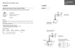
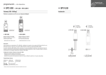
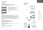
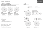
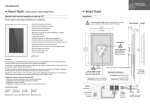
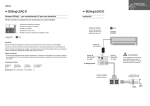
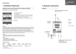
Graphic controller MEKBUS V0.1 USER MANUAL Parque Tecnológico de Asturias, Parcela 50, 33428 Llanera – Asturias - Spain Tel (+34) 985 118 859 Fax (+34) 984 283 560 [email protected] www.ingeniumsl.com TECHNICAL SUPPORT Tel (+34) 985 113 339 [email protected] USER MANUAL MEKBUS - V0.1 Index 1 General description ______________________________________________________________ 2 2 Technical description _____________________________________________________________ 3 3 2.1 MEKBUS __________________________________________________________________________ 3 2.2 MEKBUS - G _______________________________________________________________________ 3 Operation modes ________________________________________________________________ 4 3.1 3.1.1 3.1.2 3.2 3.2.1 3.2.2 3.2.3 3.2.4 4 Pages_____________________________________________________________________________ 4 Point to point ______________________________________________________________________________ 4 Scenes ___________________________________________________________________________________ 7 Menu ____________________________________________________________________________ 7 Timings ___________________________________________________________________________________ 8 Day and hour _____________________________________________________________________________ 10 Intrusion alarm ___________________________________________________________________________ 11 Presence simulation _______________________________________________________________________ 13 Installation ____________________________________________________________________ 14 4.1 MEKBUS _________________________________________________________________________ 14 4.2 MEKBUS-G _______________________________________________________________________ 15 Graphic controller 1 de 16 USER MANUAL MEKBUS - V0.1 1 G ENERAL DESCRIPTION The MEKBUS is a 4,3" color touch screen to control and monitor elements in a KNX installation. Two models available: Resistive: MEKBUS Capacitive: MEKBUS-G Designed to replace conventional switches and push-buttons, it allows to include 4 different pages to locate icons upon 3D drawings, plans, pictures, etc. and to control up to 20 installation points and to execute up to 20 programmable scenes by those allusive icons. Characteristics: - 4 different pages to locate icons upon 3D drawings, plans, pictures, etc. 20 point to point controls with different representative icons (lights, blinds, climate control, etc.) 20 scenes execution with a maximum of 64 events each. Up to 10 weekly timing programming Possibility to arm / disarm alarm and to activate presence simulation. Possibility of managing an independent climate area adding a temperature sensor (ref: STIBUS-SD) in the microSD slot Real presence simulation. Programmable from a specific application trough microSD card (2GB máx. FAT16 format). Graphic controller 2 de 16 USER MANUAL MEKBUS - V0.1 2 T ECHNICAL DESCRIPTION 2.1 MEKBUS 4,3" COLOR RESISTIVE TOUCH SCREEN - Supply - 29 Vcc from auxiliary power supply or from KNX BUS. - Consumption (depends on source): o o Auxiliary Power Supply 18-30Vdc (Recommended) 80 mA from auxiliary power supply. 1mA from KNX BUS KNX BUS (Optional) 80mA from KNX BUS - Size – 145x86x10mm. - Mounting - On universal distribution box, screwed on wall. - Programming card - MicroSD 2GB max. FAT16 format. 2.2 MEKBUS - G 4,3" COLOR CAPACITIVE TOUCH SCREEN - Supply - 29 Vcc from auxiliary power supply or from KNX BUS. - Consumption (depends on source): o o Auxiliary Power Supply 18-30Vdc (Recommended) 80 mA from auxiliary power supply. 1mA from KNX BUS KNX BUS (Optional) 80mA from KNX BUS - Size – 129x88x4mm (13 mm depth). - Mounting: o o o - Surface. Flush mounting with box (included) On universal distribution box, screwed on wall Easily mounting on plasterboard wall Programming card - MicroSD 2GB max. FAT16 format. Remarks Feed low voltage lines (BUS and inputs) in separate ducting to that of power (230V) and outputs to ensure there is enough insulation and avoid interferences. Do not connect the main voltages (230 V) or any other external voltages to any point of the BUS. Graphic controller 3 de 16 USER MANUAL MEKBUS - V0.1 3 O PERATION MODES In the main window of the MEKBUS you can have up to 4 different pages, with point to point icons that control lights, blinds, etc. individually or scenarios: a group of actions that are executed simultaneously. 3.1 P AGES Main window shows pages that you have included in your project (3D drawings, plans, pictures, etc.). 4 pages maximum. Over those pages, you can find icons linked to point to point controls or to events. All of them should be programmed using the application we will see in ¡Error! No se encuentra el origen de la referencia. ¡Error! No se encuentra el origen de la referencia. If the project has more than one page, you can shift between them by simply dragging your finger left or right, depending which page you want to display. If you drag from right to left will change to the next page. If you drag from left to right will change to the previous one. Below are some of the most common controls which are possible to include in the installations. 3.1.1 POINT TO POINT The point to point row (upper one) allows to select up to 16 elements of the installation to be controlled individually. The following icons are available: On / Off lightning: activate or deactivate the lightning of a zone (name indicated below) and shows the actual state of the light. Graphic controller 4 de 16 USER MANUAL MEKBUS - V0.1 Dimmer lightning: This icon shows the different lightning level. The level desired can be set by pressing it. Use the arrow icon to return to the main menu. Thermostat: By pressing this icon we access to a window that shows the actual temperature value (left) and the desired value (right). Slide the finger up and down to increase or decrease the set value. Use the arrow icon to return to the main menu. Use the buttons below to set the operation mode of the thermostat (winter mode, summer mode, mixed, etc.) Pushbutton: By pressing this icon can be changed the state of any on / off output of the installation. Climate: By pressing this icon can be changed the state of any on / off output of the installation. Flooding: By pressing this icon can be changed the state of any on / off output of the installation. Watering: By pressing this icon can be changed the state of any on / off output of the installation. Graphic controller 5 de 16 USER MANUAL MEKBUS - V0.1 Blind control: This icon shows the state of a blind. By pressing it we access to a window that allows to set the blind position by sliding up and down the finger. Use the arrow icon to return to the main menu. Sound control: By pressing this icon we access to a new window that allows to set the volume and select the channel of a SoniBUS. Press over the channel box to change it and slide the finger up and down to increase or decrease the volume. Use the arrow icon to return to the main menu. The available functions depend on the user’s needs and can vary by programming. Graphic controller 6 de 16 USER MANUAL MEKBUS - V0.1 3.1.2 SCENES Each scene is a group of actions that are executed simultaneously. These scenes can only be configured by programming. A scene will be executed by pressing the corresponding icon (name of the scene indicated below). The icon will remain on while the scene is in execution. For example, a usually programmed scene is one to control every light or every blind in the house. By pressing the scene called “ALL OFF” we can switch off every light of the house so it is not necessary to switch off each room individually or by pressing the scene “ALL DOWN” we can close every blind. The available scenes depend on the user’s needs and can vary by programming. 3.2 M ENU There is another window with fixed icons that is used to manage the intrusion alarm, program timings, activate or deactivate the presence simulation and to set date and hour. Press and slide up to access to this menu. To come back to the pages control, press and slide down. The appearance of this menu will be: Graphic controller 7 de 16 USER MANUAL MEKBUS - V0.1 Next paragraphs contain explanations for each tool. 3.2.1 TIMINGS The timings allow to set the day and hour of the week when the MEKBUS executes any scene. We can program up to 10 timings per week. Press the corresponding icon to show the timings menu. First, select the number of timing to use and the scene that will be scheduled (they must be programmed before) with left and right arrows in the top right corner of the screen. Then, press over the hour to set the hours and minutes of execution with the keyboard. Note: The hour is in 24h format. Graphic controller 8 de 16 USER MANUAL MEKBUS - V0.1 After that, select the days of the week in the bottom of the screen just by pressing on them to activate and deactivate. The initial indicates that the day is activated and the scene will be executed and a hyphen indicates that it is deactivated for this day. Finally, activate or deactivate the timing by pressing over the clock on the left. If the clock is on it indicates that the scene is scheduled and will be executed. When there is any timing scheduled for the current day, the small clock on the bottom right corner of the screen will remain on. Press enter to go back to the options menu. Graphic controller 9 de 16 USER MANUAL MEKBUS - V0.1 3.2.2 DAY AND HOUR The MEKBUS is a device that does not keep the hour exactly by itself, it requires an RTC (real time clock) to update the hour when it is rebooted. In case of do not having it in the installation, it is possible to set the day and hour manually from this menu. Press and hold for some seconds over the hour, minutes or seconds to set a new value with the keyboard. Note: The hour is in 24h format. The day of the week can be change in the same way. Press and hold to set a new day with the keyboard, where the number 0 is Sunday and 6 is Saturday. Note: When the device is disconnected from the power supply it is necessary to set the day and hour manually. If the installation incorporates the Ingenium RTC it is done automatically (see the RTC documentation for further information). Press over any point of the screen to go back to the main menu. Graphic controller 10 de 16 USER MANUAL MEKBUS - V0.1 3.2.3 INTRUSION ALARM This icon shows the intrusion alarm menu where the alarm can be activated or deactivated from. The MEKBUS can manage up to 4 different zones. Activation / Deactivation Firs, select the zone to be activated by the right and left arrows on the top of the screen and then press over the text “press to arm” at the bottom of the screen. Enter the password with the keyboard and press ok to validate. Each zone can be activated or deactivated with 5 different codes, which are initially configured as: Code 1: 1111 (minimum priority) Code 2: 2222 Code 3: 3333 Code 4: 4444 Code 5: 5555 (maximum priority) To activate or deactivate the intrusion alarm, enter a code which could be any of the them. Take into account that the codes are prioritized, where code 1 is minimum priority and 5 is the maximum. For example, if the alarm is activated by the code 4 it can only be deactivated by an equal of higher code (4 or 5). While the alarm is being activated, the small man at the bottom right corner of the screen is blinking. When the screen receives the activation confirmation (after 30 seconds typically) it remains on. Press enter to go back to the options menu. Graphic controller 11 de 16 USER MANUAL MEKBUS - V0.1 Password change Press and hold over the man on the left in the intrusion menu to change the activation passwords. To change any password, the screen requires first to enter the highest priority password (administrator). Then, select the level of password to be changed by pressing form 1 to 5 on the keyboard and enter the new one twice to confirm it. If the level selected is 5, you will change the administrator code. Graphic controller 12 de 16 USER MANUAL MEKBUS - V0.1 3.2.4 PRESENCE SIMULATION The presence simulation allows to copy the last actions done by the customer and reproduces them as if there were people at home, switching on and off the lights, raising the blinds, etc. Press over this icon to show the presence simulation menu and activate it by entering any intrusion code and pressing ok with the keyboard. When it is activated, any code is required to deactivate it, just press the screen. When the presence simulation is activated, the small house icon on the bottom right corner of the screen will remain on. Press enter to go back to the options menu. Graphic controller 13 de 16 USER MANUAL MEKBUS - V0.1 4 I NSTALLATION 4.1 MEKBUS Graphic controller 14 de 16 USER MANUAL MEKBUS - V0.1 4.2 MEKBUS-G Graphic controller 15 de 16 Parque Tecnológico de Asturias, Parcela 50, 33428 Llanera – Asturias - Spain Tel (+34) 985 118 859 Fax (+34) 984 283 560 [email protected] www.ingeniumsl.com