1
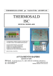
TEMPERATURE CONTROLLER FOR IMPULSE SEALING
THERMOSALD
UPSCR
AUTOMATIC CALIBRATION
•
•
•
•
•
•
MANUAL BALANCING at first start up
AUTOMATIC BALANCING at sealing band change
BURN IN of sealing band
AUTOMATIC POWER FREQUENCY SWITCHING
ENERGY CONTROL ON SEALING BAND
485 SERIAL INTERFACE to exchange data to supervisor
MAINTENANCE & OPERATIONS MANUAL
Mod. UPSCR_N_V5 (M_V4)
3E S.r.l. -
Via del Maccabreccia 37/a - 40012 LIPPO DI CALDERARA ( BOLOGNA )
Tel. ++39 051 6466225
e-Mail : [email protected]
Fax ++39 051 6426252
Indirizzo internet : www.3e3e3e.com
MAINTENANCE & OPERATIONS MANUAL:
0
WARNINGS
0.1
SAFETY PRECAUTIONS
cod. UPSCR_N_V5_MUM_2001/06
- Never use the equipment in explosive atmospheres or with explosive materials.
- Never use the equipment with flammable material without first taking the
required safety precautions.
- Never turn on the temperature controller power circuit when the safety guards are
open.
- Do not use the temperature controller for tasks other than those it is designed for
i.e to control the temperature of bands or wires for industrial-grade sealing.
Contact our engineering department for information regarding specific
applications.
- Do not deliver electrical power to the temperature controller if the protective
cover has been removed for special servicing on the electronic system.
- Operate the equipment by following the instructions contained herein.
- Employ qualified and well-trained personnel, familiar with the technology used
to install the equipment and put it into service.
- Use bands or wires having an adequate positive temperature coefficient ( > 1 x
10E-3)
- When the machine is running under normal conditions, make sure the heat sink of
the controller does not exceed 60°C . If this happens, increase heat sink
ventilation or contact our engineering department.
THERMOSALD UPSCR_N_V5 – USE AND MAINTENANCE MANUAL
Page N.
2
- Rev. 2006 / 07
- Tot.
44
0.2 COMPLIANCE WITH ELECTRO-MAGNETIC STANDARDS – CE KITE MARKS
Directives which apply :
•
•
•
Low voltage electrical codes : 73/23 CEE - 9368 CEE (in force since 01/01/97)
Elecro-magnetic compatibility : 89/336 CEE - 92/31 CEE - 93/68 CEE ( in force since 01/01/96 )
Machine directive : 89/392 CEE - 91/368 CEE - 93/68 CEE ( in force since 01/01/95 )
NOTE - this directive does not automatically apply to the elecronic equipment; our controllers are designed to conform
with the directive if installed correctly as described in this user's manual.
Electro-magnetic compliance tests :
Test conditions :
• Mains supply filter Mod. Siemens B84112-B-B60 ( 115 / 250 V - 6A - 50/60 Hz )
• Temperature controller connecting cable and standard panel 3ESD0035E ( 5 m )
• Input power cables (3 m long)
• Band output cables (10 m long)
Safety tests :
• The criteria indicated in the EN50082-2 directive have been followed: general standards regarding safety in industry.
• IEC 1000-4-2 ( IEC 801-2/1991): STATIC ELECTRICITY DISCHARGE ( ESD )
• IEC 1000-4-3 ( CEI 801-3 ): RADIATED ELECTRO-MAGNETIC FIELD
• IEC 1000-4-4 ( CEI 801-4 ): FAST TRANSIENT OSCILLATIONS ( FAST TRANSIENT / BURST )
• ENV50141: MAINS PICKUP INTERFERENCE
Emissions tests :
• The criteria specified in the EN50081 -2 directive have been followed: general rules regarding emissions in industry
• EN55011 ( CEI 110-6 ): LIMITS AND METHODS OF MEASURING RADIO INTERFERENCE PRODUCED BY
INDUSTRIAL, SCIENTIFIC AND MEDICAL EQUIPMENT ( ISM )
Compliance certificate :
• The temperature controller passed the compliance tests and is considered a class B device.
• The manufacturer states that the temperature controller fully complies with current council directives as regards electromagnetic compatibility, 89/336 CEE standards and following amendments
• The manufacturer states that the temperature controller fully complies with current low voltage electrical codes 73/23
CEE and subsequent amendments.
THERMOSALD UPSCR_N_V5 – USE AND MAINTENANCE MANUAL
Page N.
3
- Rev. 2006 / 07
- Tot.
44
CONTENTS
0
0.1
0.2
1
1.1
1.2
2
2.1
2.2
2.3
3
3.1
3.2
3.3
3.4
3.5
3.6
4
4.1
4.2
4.3
4.4
4.5
4.6
5
5.1
5.2
5.3
5.4
5.5
6
6.1
7
7.1
Annex A
Annex B
Annex C
Annex D
Annex E
Annex F
Annex G
WARNINGS
SAFETY PRECAUTIONS
COMPLIANCE WITH ELECRO-MAGNETIC STANDARDS
DESCRIPTION
GENERAL DESCRIPTION
BLOCK DIAGRAM
WIRING DIAGRAM AND DIMENSIONS
LIST OF CHANGE-OVER SIGNALS
WIRING DIAGRAM
PANEL – BOARD CONNECTING CABLE DIAGRAM
INSTALLATION
ANALYSIS OF APPLICATION
CALCULATION OF SEALING BAND RESISTANCE
THERMOSALD CHOISE
POWER TRANSFORMER CHOISE
PROTECTIVE DEVICE CHOISE
ADVICES TO DEVELOP ELECTRIC CONNECTIONS
START UP
START UP – START UP WITH MASTER RESET
SETTING THE PRE-HEATING AND/OR SEALING TEMPERATURES
WRITING DOWN THE MACHINE DATA LISTS
SPECIAL FUNCTION ENERGY CONTROL
SPECIAL FUNCTION 485 SERIAL INTERFACE AND FIELD BUS
UP-DATE OLD MACHINES
MAINTENANCE
CHANGING THE SEALING BAND WITH MACHINE COLD
CHANGING THE SEALING BAND WITH MACHINE HOT
TROUBLESHOOTING
THERMOREGULATOR MAINTENANCE
GRIPPER JAWS MAINTENANCE
SPECIFICATIONS
SPECIFICATIONS
DETAILS FOR ORDER FORM
DETAILS FOR ORDER FORM
TYPICAL SEALING CYCLE
MACHINE DATA LIST
SETTING DATA LIST
FAULTS AND WARNINGS LIST ( CAUSES - REMEDIES )
DIMENSIONS
MULTIVOLTAGE TRANSFORMERS TECHNICAL FEATURES
STAR UP CARD
THERMOSALD UPSCR_N_V5 – USE AND MAINTENANCE MANUAL
Page N.
4
- Rev. 2006 / 07
- Tot.
44
1
DESCRIPTION
1.1 GENERAL DESCRIPTION
•
APPLICATION: Impulse heat-seal technology is used to seal, rapidly and with great accuracy, polyethylen films,
polyprophilene films, single-component plastic films, multilayer plastic films in general, that must reach their melting
temperature and a cool down immediately to avoid deformations.
•
OPERATING PRINCIPLES: To execute impulse sealing, use a sealing bar with a sealing band o wire electrically
insulated from earth, supplied by an equipment specific for impulse sealing, i.e. an impulse thermoregulator. This
equipment must supply the power required to heat the band at the desired sealing temperature in an extremely short time
and maintain the desired temperature with high precision during all the sealing operations; No additional probe are
required, the equipment simpy reads the feedback signals from the bands and controls the heating current with a closedloop circuit. The termoregulator first receives a pre-heat signal from the outside so that the sealing bar can reach a
required pre-heat temperature not far from sealing temperature before starting works. The thermoregulator further
receive a sealing signal from the outside so that the sealing bars can reach the correct sealing temperature when brought
together.
•
MAIN FEATURES: The thermoregulator UPSCR_M_V4 is manufactured in 3 versions, differrent only in current,
30/60/90 Ampere; it is interchangeable with all thermoregulators of our company, manufactured before.
With the last software release, the thermoregulator is very easy to use: it works as a thermometer, whose probe is the
band itself: at start up, an analog balancing is done, an automatic burn-in is possible to do, the machine is ready to
work.
At change of band, an automatic balancing is done, an automatic burn-in is possible to do, the machine is ready to
work.
The thermoregulator do many controls and locate faults referring to the display; it is also possible analise bands by
display.
It’s possible enable a special function to control power delivered to bands and increase so the safety.
It’s possible enable a special function to exchange data with a supervisor by serial interface and set temperatures from
distance.
•
DIAGNOSTICS: The temperature controller comes with an efficient diagnostics system capable of identifying faults
which have occured during the production process, indicating the cause and suggesting the remedies required to restore
normal operating conditions.
•
RS485 SERIAL INTERFACE: The low cost option /RS485 let user to interface thermoregulator with PLC or PC with
or without digital panel; in this way it’s possible to exchange RUN TIME data, SETTING data and MACHINE data;
with an external temperature probe connected to PLC, it’s possible read temperature of the bar and calibrating the
machine with a very high precision
THERMOSALD UPSCR_N_V5 – USE AND MAINTENANCE MANUAL
Page N.
5
- Rev. 2006 / 07
- Tot.
44
1.2 BLOCK DIAGRAM
CONTROL
PANEL
MAINS
MAINS
TRANSF.
CONTROL
CIRCUIT
POWER
BAND
THERMOSALD UPSCR_N_V5 – USE AND MAINTENANCE MANUAL
Page N.
6
- Rev. 2006 / 07
- Tot.
44
2
WIRING DIAGRAM AND DIMENSIONS
2.1 LIST OF CHANGE-OVER SIGNALS
CN1
POWER
(Power circuit supply synchronised with control circuit supply )
ALTERNATING CURRENT SUPPLY
ALTERNATING CURRENT SUPPLY
BAND +
BAND EARTH
(4 - 6 sq.mm)
(4 - 6 sq.mm)
(4 - 6 sq.mm)
(4 - 6 sq.mm)
(4 - 6 sq.mm)
PIN 1
PIN 2
CONTROL CIRCUIT SUPPLY
(Control circuit supply synchronised with power circuit supply )
230 Vac ( 0.1A absorption, max)
230 Vac ( 0.1A absorption, max)
(1sq.mm)
(1sq.mm)
CN3
PIN1
PIN2
PIN3
PIN4
PIN5
PIN6
PIN7
PIN8
CONTROLS
COMMON 0 V PLC
PRE-HEAT SIGNAL FROM PLC, 24V DC ( 12 mA absorption, max)
SEALING SIGNAL FROM PLC, 24V DC ( 12 mA absorption, max)
SEALING FAULT (CONTACT N.C.) cosΦ = 1
250V 8A
SEALING FAULT (CONTACT N.C.) cosΦ = 0.4 250V 5A
BAND REFERENCE +
BAND REFERENCE SIGNAL LEAD SCREEN (do not connect from the machine side)
(0.5 sq.mm)
(0.5 sq.mm)
(0,5 sq.mm)
(0,5 sq.mm)
(0,5 sq.mm)
(0,5 sq.mm)
(0,5 sq.mm)
(1 sq.mm)
CN4
PIN1
PIN2
PIN3
PIN4
PIN5
PIN6
PIN7
PIN8
DISPLAY CONSOLE
Supply, +5V
Supply, 0 V
Data
Clock
Key
Key
Key
Key
CN5
PIN1
PIN2
PIN3
PIN4
PIN5
PIN6
PIN7
PIN8
RS485 SERIAL INTERFACE
PIN1
PIN2
PIN3
PIN4
PIN5
CN2
Screened
Screened
Screened
Screened
Screened
Screened
Screened
Screened
(0,25 sq.mm)
(0,25 sq.mm)
(0,25 sq.mm)
(0,25 sq.mm)
(0,25 sq.mm)
(0,25 sq.mm)
(0,25 sq.mm)
(0,25 sq.mm)
Channel A-
Screened
(0,25 sq.mm)
Channel B+
Screened
(0,25 sq.mm)
THERMOSALD UPSCR_N_V5 – USE AND MAINTENANCE MANUAL
Page N.
7
- Rev. 2006 / 07
- Tot.
44
2.2 WIRING DIAGRAM
SEALING FAULT
REF.+
REF.EARTH
PRE-HEATING SIGNAL (INPUT FROM PLC)
SEALING SIGNAL (INPUT FROM PLC)
EARTH
BAND
TRANSFORMER 1000VA
EMERGENCY
STOP BUTTON
board faulty
EMC FILTER
- NOTE
The power circuit supply ( CN1/1 and CN1/2 ) MUST BE synchronised with the control circuit
supply ( CN2/1 and CN2/2 ).
CN1/5 should be connected to the EARTH ELECTRODE of the machine by using a yellowgreen wire whose size should be >= that of the power leads.
THERMOSALD UPSCR_N_V5 – USE AND MAINTENANCE MANUAL
Page N.
8
- Rev. 2006 / 07
- Tot.
44
2.3 PANEL – BOARD CONNECTING CABLE DIAGRAM
•
Use a 8 x 0,22 multi-core screened cable. The screen must be wired to both connectors. It is
advisable to run this cable away from transformer or unscreened power leads.
Canon 9-pin male connector
Board side
Canon 9-pin female connector
Panel side
1 + 5V
___________________________________________
GREEN
1 + 5V
2 0V
___________________________________________
RED
2 0V
3 Data
___________________________________________
WHITE
4 Clock
___________________________________________
YELLOW
5 Key
___________________________________________
ORANGE
5 Key
6 Key
___________________________________________
BROWN
6 Key
7 Key
___________________________________________
BLACK
7 Key
8 Key
___________________________________________
BLUE
8 Key
3 Data
4 Clock
THERMOSALD UPSCR_N_V5 – USE AND MAINTENANCE MANUAL
Page N.
9
- Rev. 2006 / 07
- Tot.
44
3 - INSTALLATION
3.1 – ANALYSIS OF APPLICATION
BEFORE BEGINNING THE FIRST INSTALLATION, READ CAREFULLY THE
WARNINGS AT CHAPTER 0 AND PARTICULARLY THE SAFETY PRECUTIONS AT
CHAPTER 0.1 AND COMPLIANCE WITH ELECTRO-MAGNETICS STANDARDS AT
CHAPTER 0.2.
IT IS ENOUGH FOLLOW STEP TO STEP THE FOLLOWING INSTRUCTIONS TO START
UP THERMOREGULATOR WELL; FOR ANY QUESTIONS DON’T EXITATE TO
CONTACT OUR TECHNICAL OFFICE.
• WHICH BAND CAN USE TO HAVE THE MAXIMUM?
If You like You can contact our technical office to choise band
Material:
• Original bands by 3E in special alloy
•
NiCr80/20
• Altro:
Good
No good
Contact our technical office
Profile:
•
•
•
•
•
•
•
•
•
Chamfered (tapered edge)
Flat
Concave (grooved)
Double
Beaded
T-Shape
Cutting wire
Endless steel bands
Other
…………………….
…………………….
…………………….
…………………….
…………………….
…………………….
…………………….
…………………….
…………………….
Geometrical Dimensions:
•
•
•
•
•
•
•
Width: LARG=
Thickness: SP=
Length : L-TOT=
Copper/Silver Ends: L-RAM=
Copper/Silver in the center: L-RAMC=
Teflon in the center: L-TEFL=
Other:
…………………….
…………………….
…………………….
…………………….
…………………….
…………………….
…………………….
[mm]
[mm]
[mm]
[2 x mm]
[mm]
[mm]
THERMOSALD UPSCR_N_V5 – USE AND MAINTENANCE MANUAL
Page N.
10
- Rev. 2006 / 07
- Tot.
44
• CALCULATION OF THE USABLE BAND LENGTH
It’s the length of the part not coppered; it’s calculated by the following formula:
L-UTIL = LTOT – (LRAM x 2) – LRAMC)
Usable length: L-UTIL =
…………………….
[mm]
…………………….
[mmq]
• CALCULATION OF THE BAND SECTION
The band section is calculated by the following formula:
SEZ = LARG x SP in mmq
Section:
SEZ =
3.2 - CALCULATION OF SEALING BAND RESISTANCE
If You USE AN ORIGINAL band 3E included in the underlying tables, You can calculate band resistance using the
tables and applying the following formula:
1–
2–
3–
single band =
2 bands in series =
2 bands in parallel =
R-BAND = R0 x L-UTIL [ mt. ]
R-BAND = R0 x L-UTIL x 2 [ mt. ]
R-BAND = R0 x L-UTIL / 2 [ mt. ]
R0 =
L – UTIL =
Specific resistance of the band [ Ω / mt ]
Usable length of the band [ mt. ]
If You DON’T USE AN ORIGINAL band 3E included in the underlying tables, You must measure the band resistance
directly on te contact with a precision instrument.
Resistance: R-BAND=
…………………….
[Ω]
THERMOSALD UPSCR_N_V5 – USE AND MAINTENANCE MANUAL
Page N.
11
- Rev. 2006 / 07
- Tot.
44
•
CHAMFERED SPECIAL ALLOY ELEMENTS RESISTANCES CHART
Band width
(mm)
1.5
2
3
3
3
3
4
4
5
5
6
6
8
8
•
Band thickness
(mm)
0.3
0.3
Specific resistance R0
Ω / mt
0.9
0.6
BEADED SPECIAL ALLOY ELEMENTS RESISTANCES CHART
Band width
(mm)
4
4
6
6
•
Specific resistance R0
Ω / mt
1.67
1.59
2.95
1.95
1.50
1.27
1.40
0.96
0.8
0.69
1.6
0.72
1.2
0.51
T-SHAPE SPECIAL ALLOY ELEMENTS RESISTANCES CHART
Band width
(mm)
2.8
4
•
Band thickness
(mm)
0.3
0.25
0.1
0.15
0.2
0.25
0.15
0.25
0.2
0.25
0.1
0.2
0.1
0.2
Band thickness
(mm)
0.15
0.25
0.15
0.25
Specific resistance R0
Ω / mt
1.4
0.9
0.99
0.6
CONCAVE SPECIAL ALLOY ELEMENTS RESISTANCES CHART
Band width
(mm)
2.8
Band thickness
(mm)
0.3
Specific resistance R0
Ω / mt
0.9
THERMOSALD UPSCR_N_V5 – USE AND MAINTENANCE MANUAL
Page N.
12
- Rev. 2006 / 07
- Tot.
44
3.3 THERMOSALD CHOISE
• WHAT TYPE OF THERMOREGULATOR YOU NEED TO CHOOSE (30 / 60 / 90 AMPERE?)
The choise depend on the band section and on the connnection in parallel or series.
In the next table, You can see some example of choosing.
For different bands You can calculate about 30 Ampere / mmq.
SECTION
(SEZ.)
1
1
1,2
1,2
MODEL
(RATED I)
30A
30A
30A
30A
CONFIGURATION
PARALLEL
4 x 0,25
5 x 0,2
6 x 0,2
8 x 0,15
NO
NO
NO
NO
SECTION
(SEZ.)
2
2
2,4
2,4
MODEL
(RATED I)
60A
60A
60A
60A
CONFIGURATION
PARALLEL
4 x 0,25
5 x 0,2
6 x 0,2
8 x 0,15
SI
SI
SI
SI
SECTION
(SEZ.)
3,2
MODEL
(RATED I)
90A
CONFIGURATION
PARALLEL
8 x 0,2 x 2
SI
Thermoregulator model:
x2
x2
x2
x2
UPSCR_M_V4_100…….
ACTIVE I
MAXIMUM
60 Amp
60 Amp
60 Amp
60 Amp
SHORT C.
CURRENT
100 Amp
100 Amp
100 Amp
100 Amp
ACTIVE I
MAXIMUM
120 Amp
120 Amp
120 Amp
120 Amp
SHORT C.
CURRENT
140 Amp
140 Amp
140 Amp
140 Amp
ACTIVE I
MAXIMUM
180 Amp
SHORT C.
CURRENT
210 Amp
[ 30/60/90 Ampere ]
THERMOSALD UPSCR_N_V5 – USE AND MAINTENANCE MANUAL
Page N.
13
- Rev. 2006 / 07
- Tot.
44
3.4 - POWER TRANSFORMER CHOISE
• WHAT TYPE OF TRANSFORMER YOU MUST CHOOSE?
The choise depend on the rated current oh the thermoregulator choosed.
For the first start up, we recommend to use the original multi-voltage power transformers by 3E, specific for the
thermoregolators 30 / 60 / 90 Ampere.
For the following start up we can supply original single voltage power transformers by 3E, specific for the thermoregolators
30 / 60 / 90 Ampere.
If You prefer to use a different transformer from above refer to technical characteristic on this book, see ANNEX F –
MULTIVLTAGE TRANSFORMER TECHNICAL FEATURES.
• WHICH VOLTAGE ON THE SECONDARY OF POWER TRASFORMER YOU MUST CHOOSE?
The choise depend on the rated current of thermoregulator (30/60/90) and on the resistance of the bands R-BAND
Calculations:
(V SECONDARY lowest
V SECONDARY OPTIMUM
V SECONDARY highest
= R-BAND x I rated
= R-BAND x I rated x 1.5
= R-BAND x I rated x 2
- Example:
If you must connect a band of resistance 0.4 Ohm, with a thermoregulator 60 Ampere, the V SECONDARY OPTIMUM
VOLTAGE will be 0.4 Ohm x 60 Ampere x 1.5 = 36 Volts a.c..
Trasformer:
POWER =
PRIMARY =
SECONDARY =
…………………….
…………………….
…………………….
[ VA ]
[V]
[V]
THERMOSALD UPSCR_N_V5 – USE AND MAINTENANCE MANUAL
Page N.
14
- Rev. 2006 / 07
- Tot.
44
3.5 - PROTECTIVE DEVICE CHOISE
•
WHICH PROTECTIVE DEVISE IS TO CHOOSE?
On the 220 supply voltage of logic, an internal fuse inside thermoregulator protect the internal trasformer and
circuits.
It’s necessary protect only 220 Va.c. supply cable fromshort circuit in compliance with the notmatives IEC204.1
On the supply voltage of power, a power transformer must be protected on the primary and on the secondary; see
bottom some examples of calculations.
The suggested protections must be controlled by the designer in compliance with the application.
Thermoreg. 30 Amp. – transformer 800VA
Thermoreg. 60 Amp. – transformer 1400VA
Thermoreg. 90 Amp. – transformer 2000VA
- Primary 230V: Automatic breaker 6A type D (o del-action-fuse)
- Primary 400V: Automatic breaker 3A type D (o del-action-fuse)
- Secondary: Automatic breaker 40 A type D (o del-action-fuse)
- Primary 230V: Automatic breaker 10A type D (o del-action-fuse)
- Primary 400V: Automatic breaker 6A type D (o del-action-fuse)
- Secondary: Automatic breaker 63 A type D (o del-action-fuse)
- Primary 230V: Automatic breaker 16A type D (o del-action-fuse)
- Primary 400V: Automatic breaker 10A type D (o del-action-fuse)
- Secondary: Automatic breaker 100 A type D (o del-action-fuse)
THERMOSALD UPSCR_N_V5 – USE AND MAINTENANCE MANUAL
Page N.
15
- Rev. 2006 / 07
- Tot.
44
3.6 – ADVICES TO DEVELOP ELECTRIC CONNECTIONS
•
WHICH ACTIONS ARE TO DO, TO HAVN’T PROBLEMS DURING STARTING UP?
Use original power transformers by 3E
For the first start up, we recommend to use the original multi-voltage power transformers by 3E, specific for the
thermoregolators 30 / 60 / 90 Ampere.
For the following start up we can supply original single voltage power transformers by 3E, specific for the thermoregolators
30 / 60 / 90 Ampere.
If You prefer to use a different transformer from above refer to technical characteristic on this book, see ANNEX F –
MULTIVLTAGE TRANSFORMER TECHNICAL FEATURES.
Use original bands by 3E in special alloy
For the first start up this is indispensable.
For the following start up, we advise to continue to use the original bands to don’t loose stability.
In the market You can find other good bands; don’t use bands of any materials; for informations contact our commercial
office.
Execute wiring as advised in the WIRING NOTE and in the FOLLOWING PICTURES (SEE FOLLOWING
PAGES)
Pay much attention to the connections on the machine of the reference wire and of the power cables to have no problems at
starting up and in the future; contact our technical office for more informations.
Connect in phase the supply of logic (230 Volts) with the primary of power transformer (230Vac o 380 Vac).
The 230V of logic must be:
1 – The same of the primary of the power transformer (if the primary of the power transformer is 230V)
2 – In phase or out of phase 180 degree, originated by a little transformer es. 30VA - 0-400 / 0-230 (if the primary of the
power transformer is 400V)
Read diagnostic warning and act accordingly
If it happens to have some problems during start up or later, read and pay attention at the alarm number that appears on the
display panel; read the cause and the remedy in this book, see append D, and act accordingly; if the problems persist don’t
exitate to contact our technical office: the diagnostic permit to us to help You to solve problems also at distance.
It’s better to position the panel cable far from cables supplying high currents or other electrical noise sources.
In any case the panel cable is screened and protected from electrical noise.
Mount the thermoregulator leaving a rigth space around for cooling:
5 cm about for model 30Ampere
8 cm about for model 60 Ampere
10 cm about for model 90 Ampere
THERMOSALD UPSCR_N_V5 – USE AND MAINTENANCE MANUAL
Page N.
16
- Rev. 2006 / 07
- Tot.
44
•
WIRING NOTE (SEE PICTURES IN THE FOLLOWING PAGES)
L1 + L2
POWER+/POWERGROUND
USE TWISTED CABLES NOT SCREENED
USE TWISTED CABLES NOT SCREENED UP TO TERMINAL BOARD ON THE
MACHINE
USE CABLE YELLOW/GREEN SECTION>= SECTION L1,L2
TERMINAL BOARD ON THE MACHINE EVERY TERMOREGULATOR MUST HAVE AN INDIPENDENT
TERMINAL ON THE MACHINE, BECAUSE OF THE CABLES OF DIFFERENT THERMOREGULATORS MUST
NOT BE LINKED TOGETHER TO HAVE NOT INTERFERENCES.
1,2,7,8
USE FLEXIBLE CABLE (TASKER CABLE C235)
SECTION CONFORMED AT CURRENTS (>=6mmq)
3,4,5,6
USE FLEXIBLE CABLE (TASKER CABLE C235)
SECTION 1 mmq
10
USE CABLE TWISTED AND SCREENED (TWINAX IBM 7362211)
11
WIRE POWER AND REFERENCE CONNECTIONS ON THE BAND
BY DIFFERENT EYES + SCREWS OR
BY DIFFERENT EYES ON ONE SCREW
12
DO THE MECHANICAL LOCK OF THE BAND BY 2 SCREWS
SO THAT CONTACT IS FLAT AND PERFECT
13
USE BANDS COPPER OR SILVER PLATED AT THE ENDS
TO HAVE NOT ELECTRIC POTENTIAL ON THE TERMINAL
BECAUSE OF OXIDATION
14
SOMETIME IT’S POSSIBLE TO USE TEFLON COATED BANDS;
THE CONTROL IS MORE PRECISIOUS BUT MACHINE INCREASE
THE STOPS FOR CHANGING BANDS
15
USE AN ELASTIC SYSTEM TO MAINTAIN BANDS TIGHT
THERMOSALD UPSCR_N_V5 – USE AND MAINTENANCE MANUAL
Page N.
17
- Rev. 2006 / 07
- Tot.
44
•
CONNECTIONS TO THERMOREGULATOR
THERMOSALD UPSCR_N_V5 – USE AND MAINTENANCE MANUAL
Page N.
18
- Rev. 2006 / 07
- Tot.
44
•
CONNECTIONS TO SINGLE BAND
•
CONNECTIONS TO BANDS IN PARALLEL (SOLUTION ADVISED)
THERMOSALD UPSCR_N_V5 – USE AND MAINTENANCE MANUAL
Page N.
20
- Rev. 2006 / 07
- Tot.
44
•
CONNECTION BANDS IN PARALLEL (SOLUTION PASSABLE)
THERMOSALD UPSCR_N_V5 – USE AND MAINTENANCE MANUAL
Page N.
21
- Rev. 2006 / 07
- Tot.
44
4 – START UP
4.1 – START UP – START UP WITH GENERAL RESET
1 - The machine must be at ambient temperature.
2 - Pre-heat and seal remote controls must be off.
3 - Set dip switch SW+/SW- according to the rated voltage of the power transformer; see next CALCULATION
TABLE and DIP SWITCH SW+ / SW- TABLE:
CALCULATION TABLE
Example:
Sealing band = 1 Ω - RATED I = 30 A,
TRANSFORMER RATED VOLTAGE = 30 V
TRANSFORMER MAXIMUM VOLTAGE = 30 V x 1.5 = 45 V
TRANSFORMER SECONDARY VOLTAGE = Compresa fra 30V e 45V
DIP SWITCH SW+ e SW- = OFF OFF ON ON (See DIP SWITCH SW+ / SW- TABLE)
NOTE: SW+ e SW- set depend on
TRANSFORMER RATED VOLTAGE = 30V (field 26V - 35 V )
(don’t depend on TRANSFORMER SECONDARY VOLTAGE)
DIP SWITCH SW+ / SW- TABLE
Dip 1
ON
OFF
ON
OFF
ON
OFF
ON
OFF
ON
OFF
ON
OFF
ON
OFF
ON
OFF
Dip 2
ON
ON
OFF
OFF
ON
ON
OFF
OFF
ON
ON
OFF
OFF
ON
ON
OFF
OFF
Dip3
ON
ON
ON
ON
OFF
OFF
OFF
OFF
ON
ON
ON
ON
OFF
OFF
OFF
OFF
Dip4
ON
ON
ON
ON
ON
ON
ON
ON
OFF
OFF
OFF
OFF
OFF
OFF
OFF
OFF
TRANSFORMER RATED VOLTAGE
05 - 07 (TO LIGHT GREEN LED)
08 - 15
16 - 25
26 - 35
36 - 42
43 - 50
51 - 57
binary system
58 - 65
66 - 75
76 - 82
83 - 92
93 - 97
97 - 100
( TO LIGHT RED LED)
THERMOSALD UPSCR_N_V5 – USE AND MAINTENANCE MANUAL
Page N.
22
- Rev. 2006 / 07
- Tot.
44
4 –Press the keys 1 + 4 (down + reset) and, at the same time, power on the thermoregulator
- 4 blocks appear on the display; the reset procedure begins; release keys
down + reset (1 + 4).
- Thermoregulators leave our factory in reset state, then at power on 4 blocks
always appear and reset procedure begins.
- Whenever an operator needs to repeat reset procedure, he can keeps keys 1
+ 4 (down + reset) pressed 6 + 8 seconds untill on the display the 4 blocks
appear and the reset procedure begins.
4 - Release the keys 1+4 (down+reset)
5 – Display = “ P H A S ”
On the display appears “ P H A S ” to mean that logic and power supplies phase control is in progress (if logic and power
supplies are not on the same phase, “ F 0 8 3 “ fault signal is sent).
5 – Wait
6 – Display = “ V O L T ”
On the display appears “ V O L T ” to mean that TRANSFORMER SECONDARY VOLTAGE control is in progress (this
voltage must be between TRANSFORMER RATED VOLTAGE and TRANSFORMER MAXIMUM VOLTAGE).
6 – Wait
6
– Display = “ V 0. 5 0 ” -> “ V 1. 1 0 ” - USE FACTOR
On the display appears “ V ” followed by a number that informs if thermoregulator is well used or not: the right value are
included in the range V 0.6 – V 1.0; absolute maximum rating V 1.3.
V 1.0 means active current 45A (for model 30A), 90A (for model 60A), 135A (for model 90A)
7 – Wait
8 – Display = “ V D I P ” blinking
On the display blinks “ V D I P ” to remember that SW+ / SW- dip switch must be set (see CALCULATION TABLE and
DIP SWITCH SW+ / SW- TABLE).
8 - Press the RESET key
9 – Display = “ T 0 2 0 ” = 20 DEGREES – Set gripper jaws temperature or wait
(“ T 0 3 0 ” = 30 DEGREES from software release V4.9)
On the display appears the ambient (gripper jaws) temperature set on the thermoregulator.
In applications where a great precision of temperature is necessary, it is possible change this parameter and set it with the
actual gripper jaws temperature, simply pressing keys DOWN / UP.
9 - Wait
THERMOSALD UPSCR_N_V5 – USE AND MAINTENANCE MANUAL
Page N.
23
- Rev. 2006 / 07
- Tot.
44
10 – Display = “ _ B A L ” / “Temperature” – START UP COLD BALANCING BY TRIMMER
(TO TOUCH AND ROTATE ONLY IN THE COURSE OF FIRST START UP)
NOT BALANCED SYSTEM
- On the display appears alternatively “ B A L ” and “temperature value not balanced ” to
remember that green/red led balancing need to do (Note: a red bar down before “ B A L “
means unbalance towards down; a red bar up before “ B A L “ means unbalance towards up;
the wording “ T - - - “ means temperature overflow toward down).
- rotate balancing trimmer clockwise to light green led, rotate anticlockwise to light red led;
update of green/red led is 1 time in a second, so to calibrate fine it is necessary to rotate
balancing trimmer and wait up to aone second to wait update condition.
- When green and red leds are light both, the thermoregulator is balanced; we advise to read
temperature value on the display and rotate trimmer untill having 20 degree, if 20 degree is
the temperature of the gripper jaws: in any case the termoregulator will do next an automatic
perfect balancing.
BALANCED SYSTEM
- On the display appears fixed “ B 0 2 0 “, if 20 degree is temperature of the gripper jaws;
- When green and red leds are light both, the thermoregulator is balanced; we advise to read
temperature value on the display and rotate trimmer untill having 20 degree, if 20 degree is
the temperature of the gripper jaws: in any case the termoregulator will do next an automatic
perfect balancing.
10 – Press the key RESET (ON DISPLAY DISAPPEAR THE “ B “ OF “ B 0 2 0 “ AFTER SOME SECONDS)
(From software release V4.9 it is possible press also the keys DOWN + UP)
11 – Keep the key RESET pressed for 3 seconds to start the AUTOMATIC BURN-IN CYCLE
On the display appears “ H100” , to inform that the first heating at 100
degree is in progress; next the writing H200, H100, H200, H100,
H200, H100 will appear to inform that cycles of heating and colding at
200 and 100 degrees are in progress. At the end the termoregulator will
be ready to work.
Burn in cycle can be stopped before end pressing key reset.
THE MACHINE IS READY TO WORK.
NOTE: After the BURN IN cycle, sealing bands modify a little its electric characteristic, but are stable. If pay
attention can observe that temperature of sealing bands is some degree lower then before burn_in cycle. Do not
modify temperature by rotating balancing trimmer (used only in the course of first start up, after a master reset) or
pressing the up/down keys to do an automating balancing (used only after a change of the sealing band)
NOTE: It’s possible to do the machine more hot increasing HOT FACTOR value, parameter 5; From software
release V4.9 it’s possible to change it pressing the keys DOWN+T/I for 3 seconds, parameter nr. 5 appears, change
the value by key DOWN or UP, wait 6 seconds to return to main menu.
(As previous software release, it’s possible to change this parameter entering in the SETTING DATA or HOT
CALIBRATION DATA, pressing key UP+RESET 6 seconds, see ANNEX C)
THERMOSALD UPSCR_N_V5 – USE AND MAINTENANCE MANUAL
Page N.
24
- Rev. 2006 / 07
- Tot.
44
4.2 – SETTING THE PRE-HEATING AND/OR SEALING TEMPERATURES
1 – Press the keys 3+4 (T/I+RESET) for 3 seconds
The PREHEAT led on the panel start flashing and indicate the set pre-heating temperature.
2 – Press the keys UP or DOWN to change the temperature of pre-heating.
3 – Press the key RESET to switch to the temperature of sealing changing.
The WELDING led on the panel start flashing and indicate the set sealing temperature.
4 – Press the keys UP or DOWN to change the temperature of sealing.
5 – Wait 3 seconds to leave temperature setting.
4.3 – WRITING DOWN THE START UP DATA CARD
Write down the START UP DATA CARD – PAG. 1, ANNEX G
If any machine or setting data is modified, write down also START UP DATA CARD – PAG. 2.
That above lets to record start up data in the documentation of the machine; it will be useful for future verify and for starting
up of the next machines, so it will be easer to do and all machine will be equal.
4.4 - SPECIAL FUNCTION ENERGY CONTROL
•
CAN BE PERFORMED ON ALL MACHINES HANDLING SLIGHTLY FLAMMABLE MATERIAL; THIS
INCREASE REDUNDANCY AND AUTO-CONTROL THEREBY MAKING THE SYSTEM SAFER TOO
(BEFORE GOING ON, GET IN TOUCH WITH OUR TECHNICAL OFFICE FOR INSTRUCTIONS)
1 - Enter the machine data
F = 1 to Enable the control for the pre-heating procedure
F = 2 to Enable the control for the heat-sealing procedure
F = 3 to Enable the control for the pre-heating + heat-sealing procedure
2 - Pre-heat for 10 seconds
The thermoregulator acquire the power supplied in pre-heating.
3 – Start the machine running with the bags loaded
The thermoregulator acquire the power supplied in sealing.
When acquisition phase is finished, if thermoregulator detects a power on the bag out of tolerance stop in emergency.
In the case of slightly flammable materials, the machine builder must pay much attention to applications and take
right solutions for safety.
NOTE – Each time the pre-heating and sealing temperature or some machine data are changed, an automatic data
acquisition needs to be performed.
4.5 - SPECIAL FUNCTION 485 SERIAL INTERFACE AND FIELD BUS
(IN PROGRESS)
THERMOSALD UPSCR_N_V5 – USE AND MAINTENANCE MANUAL
Page N.
25
- Rev. 2006 / 07
- Tot.
44
4.6 – UP-DATE OLD MACHINES
• WOULD YOU LIKE TO UPDATE OLD MACHINES WITH NEW SOFTWARE RELEASE?
For this procedure do not exitate to contact our technical office. From Thermosald Hardware M it is possible update
machine without loose any performance; for older units needs pay attention to. This operation is easy enough, but must be
done only by skilled workers with experience. After update a careful test need to be done. We don’t take any responsibility
on ourself for damage to people or animals or things, if operations are done without our direct control.
Procedure to change the eprom:
Disconnect and detach completely the thermoregulator from electrical panel, to can work on a tooled table, with the power
connector on the left and the 2 connectors + fuse on the right. Unscrew the 4 screws on the bottom heat sink and the 6 selftapping screws on the carter; pay much attention to the internal flat, and take off the carter enlarging lightly lateral panel to
unlock the connectors; disconnect internal flat and take off completely the carter.
Inside You can see 3 boards: on the central board, with the components mounted towards inside, the eprom on socket (28
pin) You can see. Pay attention not to stretch some pins, pay attention to the polarity of the eprom; with a right tool pickup
the old eprom and mount the updated eprom (pin 1 and reference mark towards inside like as the other chips).
To close You must: connect the flat, pay much attention to mount the carter enlarging lightly lateral panel and rotating the
carter on the side of the flat; close the lateral panel; screw lightly the 4 screws on the bottom heat sink; screw tight the 6 selftapping screws on the carter; screw now tight the 4 screws on the bottom heat sink.
Mount and connect the thermoregulator.
Before power on, set DIP SWITCH in the bottom way:
SW+ / SWNO CHANGE
SW1
1=ON 2=ON 3=ON 4=ON (ALL
= ON )
IREAD
1=ON 2=OFF 3=ON 4=ON (IREAD/2 = OFF)
DO THE START UP WITH GENERAL RESET PROCEDURE – SEE CHAPTER 4.1
THERMOSALD UPSCR_N_V5 – USE AND MAINTENANCE MANUAL
Page N.
26
- Rev. 2006 / 07
- Tot.
44
5 – MAINTENANCE
5.1 – CHANGING THE SEALING BANDS WITH MACHINE COLD ( i.e. gripper jaws at ambient temperature )
•
HAVE YOU TO CHANGE THE SEALING BANDS WITH THE MACHINE AT AMBIENT TEMPERATURE,
BECAUSE OF A PROGRAMMED MAINTENANCE?
Pre-heat and seal comands are off; the machine is at ambient temperature; The sealing bands have little differences in
measure; for optimum accuracy it is possible to do an automatic cold balance to compensate the differences; it is possible
doing a burn-in cycle after, to become stable electric characteristics.
1 – Switch off power, release pre-heat and seal commands, let the gripper jaws getting cold down.
2 – Install the new sealing bands, switch on power.
3 – Keep the keys 1 + 2 (DOWN + UP) pressed for 6 seconds to make the AUTOMATIC COLD BALANCING
- On the display appears “ B A L “
- Release the key 1 + 2 (DOWN + UP)
4 - Display = “ T 0 2 0 ” = 20 DEGREES – Set gripper jaws temperature or wait
(“ T 0 3 0 ” = 30 DEGREES from software release V4.9)
On the display appears the ambient (gripper jaws) temperature set on the thermoregulator.
In applications where a great precision of temperature is necessary, it is possible change this parameter and set it with the
actual gripper jaws temperature, simply pressing keys DOWN / UP.
5 – Keep the key RESET pressed for 3 seconds to start the AUTOMATIC BURN-IN CYCLE
On the display appears “ H100” , to inform that the first heating at 100
degree is in progress; next the writing H200, H100, H200, H100,
H200, H100 will appear to inform that cycles of heating and colding at
200 and 100 degrees are in progress. At the end the termoregulator will
be ready to work.
Burn in cycle can be stopped before end pressing key reset.
THE MACHINE IS READY TO WORK.
NOTE: After the BURN IN cycle, sealing bands modify a little its electric characteristic, but are stable. If pay
attention can observe that temperature of sealing bands is some degree lower then before burn_in cycle. Do not
modify temperature by rotating balancing trimmer (used only in the course of first start up, after a master reset) or
pressing the up/down keys to do an automating balancing (used only after a change of the sealing band)
THERMOSALD UPSCR_N_V5 – USE AND MAINTENANCE MANUAL
Page N.
27
- Rev. 2006 / 07
- Tot.
44
5.2 – CHANGING THE SEALING BANDS WITH MACHINE HOT
( i.e. gripper jaws cooling down , but hot too because of inertia )
•
HAVE YOU TO CHANGE THE SEALING BANDS WITH THE MACHINE HOT, WITH THE
PRODUCTION IN PROGRESS, WITHOUT WAITING THAT GRIPPER JAWS TEMPERATURE FALLS
DOWN AT AMBIENT TEMPERATURE?
A sealing bands change, with the machine hot, with the production in progress, is less accurate then a change with the
machine cold, in a programmed maintenance, because the automatic cold balancing must not be done (an automatic cold
balance is done to compensate the differences in measure of the sealing bands).
If the application needs a very high precision, it is possible doing a quick change of the all gripper jaws with sealing bands,
and go on with the preceding procedure of CHANGING THE SEALING BANDS WITH MACHINE COLD(see par. 5.1).
Another less expensive way to work, but easier to make a mistake, is to set the parameter of ambient temperature at the
gripper jaws temperature and doing an automatic cold balancing (do not exitate to contact our technical office)
1 – Switch off power, release pre-heat and seal commands, let the gripper jaws cooling down.
2 - Install the new sealing bands, switch on power.
- If the machine is hot, must not do the automatic cold balancing.
3 – Keep the key RESET pressed for 3 seconds to start the AUTOMATIC BURN-IN CYCLE.
- Verify if burn-in is necessary in the specific application, looking at the quality of first sealing.
On the display appears “ H100” , to inform that the first heating at 100
degree is in progress; next the writing H200, H100, H200, H100,
H200, H100 will appear to inform that cycles of heating and colding at
200 and 100 degrees are in progress. At the end the termoregulator will
be ready to work.
Burn in cycle can be stopped before end pressing key reset.
THE MACHINE IS READY TO WORK.
THERMOSALD UPSCR_N_V5 – USE AND MAINTENANCE MANUAL
Page N.
28
- Rev. 2006 / 07
- Tot.
44
5.3 – TROUBLESHOOTING
•
•
•
PROBLEM: Allarm Fxxx appears on the display - VERIFY alarm list in this book (ANNEX D)
PROBLEM: In Balancing the band is hot - VERIFY that logic and power supply are in the same phase
PROBLEM: On the display You can see oscillating temperature - VERIFY that contacts of bands are good,
Verify that connections are not linked together, verify machine data and, if they are not regular, do a master reset and a
following calibration with machine cold.
5.4 – THERMOREGULATOR MAINTENANCE
Depend on the working environment, in every way not more then every 180 days.
1 – Verify that all the thermoregulator terminals are screw tight
2 – Verify the right function of emergency output by an electrical floating contact (it opens when the logic supply 230
Volts power off)
5.5 – GRIPPER JAWS MAINTENANCE
Depend on the working environment, in every way not more then every 20 days.
1 – Verify that the reference and power terminals are screw tight
2 – Verify that the connections of the bands are good without oxidation.
3 – Verify the teflon and the isolation of gripper jaws
THERMOSALD UPSCR_N_V5 – USE AND MAINTENANCE MANUAL
Page N.
29
- Rev. 2006 / 07
- Tot.
44
6 – SPECIFICATIONS
6.1
SPECIFICATIONS
LOGIC CIRCUIT SUPPLY ( CN2 )
POWER CIRCUIT SUPPLY
MAXIMUM CURRENT MOD. 30 A
MAXIMUM CURRENT MOD. 60 A
MAXIMUM CURRENT MOD. 90 A
MAINS FREQUENCY
DIGITAL CONTROLS
OUTPUT SEALING FAULT CONTACT
ACCURACY
PRE-HEATING TEMPERATURE
SEALING TEMPERATURE
SEALING TIME
COOLING TIME
AMBIENT TEMPERATURE
LEVEL OF BOARD PROTECTION
LEVEL OF DISPLAY CONSOLE PROTECTION
POWER ASSEMBLY WEIGHT
PANEL WEIGHT
PANEL-POWER ASSEMBLY EXTENSION WEIGHT
230Vac +/- 10% ( 0.1 A absorption )
10 - 100V (max 60 A absorption at 100 V)
45 AMP + 10%
90 AMP + 10%
135 AMP + 10%
50 - 60 Hz (automatic changing )
24 VDC (12 mA max. absorption )
250 V 8A cosΦ = 1
250V 5A cosΦ = 0.4
≅ +/- 1 °C
can be set from display console, 0 - 250 °C
can be set from display console, 0 - 250 °C
determined by PLC ( or precision timer)
determined by PLC ( or precision timer)
0° C +50° C
IP00
IP65
2.5 Kg
0.3 Kg
0.2 Kg
THERMOSALD UPSCR_N_V5 – USE AND MAINTENANCE MANUAL
Page N.
30
- Rev. 2006 / 07
- Tot.
44
7 – DETAILS FOR ORDER FORM
7.1 DETAILS FOR ORDER FORMS
MODEL - Description
CODE
THERMOSALD UPSCR - Impulse Thermoregulator 100V 30A
THERMOSALD UPSCR - Impulse Thermoregulator 100V 60A
THERMOSALD UPSCR - Impulse Thermoregulator 100V 90A
PANEL 3ESD0039 - Digital panel data input
CAVO 3ESD0035 - Cable panel - thermoregulator
/RS485 – RS485 Serial interface
THERMOSAL_485 – Supervisor simulator (CD+RS232-485 Box)
UPSCR_N_V5_10030
UPSCR_N_V5_10060
UPSCR_N_V5_10090
3ESD0039
3ESD0035
/RS485
3ESD0075
OPZIONAL EQUIPMENT
TRANSFORMER 1400VA/70V/30A
Impulsive transformer for Thermoregulator 30A
0 / 230 / 400 / SCH / GND = 0 / 30 / 40 / 50 / 60 / 70
3ESD0063
TRANSFORMER 1400VA/50V/60A
Impulsive transformer for Thermoregulator 60A
0 / 230 / 400 / SCH / GND = 0 / 30 / 40 / 50
3ESD0064
TRANSFORMER 2000VA/50V/90A
Impulsive transformer for Thermoregulator 90A
0 / 230 / 400 / SCH / GND = 0 / 30 / 40 / 50
3ESD0065
GRAPHIC PRINTER – Printer to report temperature graphic
3ESD0056
BANDS AND WIRES FOR SEALING
Bands and wires with many profiles, selled in meters, on specific draw,
Copper/silver ended, teflon coated.
USE AND MAINTENANCE MANUAL
OPERATOR MANUAL
UPSCR_N_V5_MUM
UPSCR_N_V5_MOP
THERMOSALD UPSCR_N_V5 – USE AND MAINTENANCE MANUAL
Page N.
31
- Rev. 2006 / 07
- Tot.
44
ANNEX A – SEALING CYCLE
NOTE - The sealing cycle showed bottom is only for example and not a standard cycle to follow
everytime. From experience we have learnt that it’s necessary modify the cycle depending on materials,
dimensions, speeds and else. For other informations don’t exitate to contact our technical office.
PRE-HEATING
SIGNAL
(IN THERMOSALD)
SEALING SIGNAL
(IN THERMOSALD)
closed
FILM GRIPPER JAWS
open
closed
BAND SEALERS
open
COOLING
FILM FEED
THERMOSALD UPSCR_N_V5 – USE AND MAINTENANCE MANUAL
Page N.
32
- Rev. 2006 / 07
- Tot.
44
ANNEX B – MACHINE DATA LIST
NOTE – The machine data must be changed only by skilled workers with experience, after getting in contact with
our technical office; the necessity to change some machine data, may be in specific applications.
TO ENTER: keep keys DOWN + RESET/MODE (1 + 4) pressed for 6 seconds ( on the display appears 0.0.0.0. ).
TO OUTPUT: Release EVERY KEY for 8 seconds.
TO LOOK NEXT PARAMETER: Press key RESET/MODE
TO INCREASE THE VALUE: Press key UP
TO DECREASE THE VALUE: Press key DOWN
•
•
•
•
•
•
•
•
•
0.0.0.0. - INITIAL STATE OF MACHINE DATA LIST
Press key RESET/MODE To look next parameter.
1.XXX - HEATING INCREASE DEGREE / 10 MS
It is the speed of temperature increase following a pre-heat or sail comand [Units degree / 10 ms].
Increase this parameter means decrease time necessary to hot the sealing band to pre-heat temperature, i.e. increase
speedy, increase overshoot, increase bands wear and tear.
2.XXX - KV PROPORTIONAL GAIN
Loop proportional gain. Increase this parameter means increase speed of loop and then increase speed of the system.
Increase too much means to do the system and temperature less stable.
3.XXX - KINT INTEGRAL GAIN
Loop integral gain. Increase this parameter means to increase the precision of the target temperature, increase the
speedy, increase the stability of the system.
Increase too much means to introduce a temperature overshoot following a pre-heat or sealing command.
4.XXX - KINT OPERATING LIMIT
5.XXX - SELECT °C / °F DISPLAY
Select the temperature display in degree Centigrade (Celsius) or Farhenheit.
6.XXX - MAINS SUPPLY FREQUENCY 50 / 60 Hz
Display electric network frequency recognized automatically at power on.
7.XXX - SELECT MAXIMUM SEALING TIME
Set the sailing time [Units seconds]. If sealing time is longer than this value, thermoregulator sends fault signal F085.
000 means that control is not active and it is possible to do continuos sealing.
8.XXX - PARTIAL SHORT CIRCUIT FACTOR
This parameter is used to set an istantaneous current threshold, above which a partial short-circuit occurs and the
thermoregulator sends fault signal F097.
The standard istantaneous current is acquired during the balancing or burn-in procedures.
THERMOSALD UPSCR_N_V5 – USE AND MAINTENANCE MANUAL
Page N.
33
- Rev. 2006 / 07
- Tot.
44
•
•
•
•
•
•
•
•
•
•
•
•
•
•
•
•
9.XXX - FAULT ENABLE
Numeric code to enable/disable some fault
0 = disable all faults in the bottom list
255 = enable all faults in the bottom list
to enable only some faults, the code is determined as follow:
ENABLE FAULT 82
1+
ENABLE FAULT 84
2+
ENABLE FAULT 86
4+
ENABLE FAULT 87
8+
ENABLE FAULT 89
16 +
ENABLE FAULT 97
32 =
----------------CODE CALCULATED
63
-----------------A.XXX - RATED CURRENT
Displays the rated current of termoregulator 30 / 60 / 90 Ampere
B.XXX - KD DERIVATIVE GAIN
Loop derivative gain. Increase this parameter means increase speed of the loop and then increase speed of the system.
Increase too much means to do the system and temperature less stable.
C.XXX - ENABLE COMPENSATION WITH SYSTEM COLD
001 = enable the special function on different initial pre-heating. For more informations do not exitate to
contact our technical office.
D.XXX - SERIAL PRINTER ENABLE
1 = enable data to be exchanged with the 3E printer model GRAPHIC PRINTER, that permits to record sealing data.
E.XXX - SEALER NUMBER FOR PRINTER
It is the number assigned to the heat sealer that allow the 3E GRAPHIC PRINTER to recognise what sealer is sending
data. For more informations do not exitate to contact our technical office.
F.XXX - ENERGY CONTROL ENABLE
1 = enable energy pre-heat control
2 = enable energy sealing control
3 = enable energy pre-heat + sealing control
H.XXX - ENERGY CURRENT TOLERANCE DURING PRE-HEATING
I .XXX - ENERGY PHASE TOLERANCE DURING PRE-HEATING
L.XXX - ENERGY CURRENT TOLERANCE DURING SEALING
O.XXX - ENERGY PHASE TOLERANCE DURING SEALING
P.XXX - ENERGY MINIMUM TEMPERATURE THRESOLD TO ACQUIRE
It is the temperature thresold over which energy acquisition cannot begin.
BARRA CODICE 1 - BURN-IN TEMPERATURE
Hot temperature of the Burn_in cycle.
Note: the Burn-in cycle is used to stabilize bands in temperature; it executes 3 cycles of heating and cooling .
BARRA CODICE 2 - BURN_IN HEATING TIME
Heating time in seconds of the Burn_in cycle.
Nota: the Burn-in cycle is used to stabilize bands in temperature; it executes 3 cycles of heating and cooling .
BARRA CODICE 3 - CYCLES NUMBER TO CHANGE 1/10000 PERIOD MAINS SUPPLY FREQUENCY
Internal parameter. Set 0 to disable alarm 63 and phase control PHLL.
BARRA CODICE 4 - MAXIMUM ERROR 1/10000 PERIOD MAINS SUPPLY FREQUENCY
Internal parameter.
THERMOSALD UPSCR_N_V5 – USE AND MAINTENANCE MANUAL
Page N.
34
- Rev. 2006 / 07
- Tot.
44
ANNEX C – SETTING DATA LIST
NOTE – The setting data must be changed only by skilled workers with experience, after getting in contact with our
technical office; the necessity to change some machine data, may be in specific applications.
NOTE – In some setting data state is possible analyse the performances of the sealing bands on machine. These
works must be done only by skilled workers with experience, after getting in contact with our technical office.
TO ENTER: keep keys DOWN + RESET/MODE (1 + 4) pressed for 6 seconds ( on the display appears 0.0.0.0. ).
TO OUTPUT: Release EVERY KEY for 8 seconds.
TO LOOK NEXT PARAMETER: Press key RESET/MODE
TO INCREASE THE VALUE: Press key UP
TO DECREASE THE VALUE: Press key DOWN
•
•
•
•
•
•
•
•
•
•
•
•
•
•
1.1.1.1. - INITIAL STATE OF SETTING DATA LIST
Press key RESET/MODE To look next parameter.
0. XXX - HEATING CURRENT FOR TEST
Allow to set the current to heat manually band and examine it [U.M. = Ampere].
1. XXX - ISTANTANEUS V-I FOR TEST
Internal parameter.
2. XXX - ISTANTANEUS IREAD FOR TEST
Internal parameter.
3. XXX - MAXIMUM ACTIVE CURRENT
Display maximum active current that the thermoregulator can supply.
45 Ampere per il termoregolatore UPSCR_M_V4_10030
90 Ampere per il termoregolatore UPSCR_M_V4_10060
135 Ampere per il termoregolatore UPSCR_M_V4_10090
4. XXX - WORKING ACTIVE CURRENT
Display active current supplied by thermoregulator: this parameter must be less than above parameter N. 3.
5. XXX - HEATING FACTOR
This parameter modify the temperature characteristic of the thermoregulator.
Increase this parameter means increase the temperature of the band.
6. XXX - V-I 100 DEGREE
Internal parameter.
7. XXX - I-V ABSOLUTE MAXIMUM RATING
Internal parameter.
8. XXX - I-V RATED
Internal parameter.
9. XXX - MAINS SUPPLY FREQUENCY
On the display switch before the number integer of mains supply frequency for 3 seconds es. 50. (Note the point on
the righ of number), then the thousandth of herz for 10 seconds es. .008 (Note the point at the left of number)
A.XXX - VOFFSET
Internal parameter.
B.XXX - MAXIMUM SEALING TEMPERATURE
Internal parameter.
C.XXX - TEMPERATURE GRADIENT – maximum temperature decrease to enable balancing
(Degrees/10 seconds)
THERMOSALD UPSCR_N_V5 – USE AND MAINTENANCE MANUAL
Page N.
35
- Rev. 2006 / 07
- Tot.
44
ANNEX D – FAULTS AND WARNINGS LIST (CAUSES – REMEDIES)
NOTA – Press the key RESET / MODE to reset every alarm
WARNINGS CAUSES
REMEDIES
UDIP
FBAL
FCAL
Fo5o
F21
F22
F23
F25
F26
F33
F34
F35
F36
F38
F39
A GENERAL RESET PROCEDURE HAS BEEN PERFORMED
Set or Verify the DIP SWITCH SW+/SW- and press the key RESET/MODE
A GENERAL RESET PROCEDURE HAS BEEN PERFORMED
Make cold balancing of led green/red by trimmer and press the key RESET/MODE
EQUIPMENT NOT CALIBRATED
Make hot automatic calibration (only previous software up to release 4.0)
ENTER THE HEATING FACTOR
Keep keys 2+4 (UP+Reset/Mode) Pressed for 6 seconds and set parameter 5 (heat factor)
(only previous software up to release 4.0)
RS485 INTERFACE ERROR(OE)
Overrun error-please wait autoreset and try again
RS485 INTERFACE ERROR(FE)
Frame error-please wait autoreset and try again
RS485 INTERFACE ERROR(RX READ INDEX)
Line error-please wait autoreset and try again
RS485 INTERFACE ERROR(TX BUFFER FULL)
Tx buffer full error-please wait autoreset and try again
RS485 INTERFACE ERROR(RX BUFFER FULL)
Rx buffer full error-please wait autoreset and try again
NO CURRENT TO THE BAND
Verify power on the transformer, Verify Voltage on CN1/1-CN1/2 connector, Verify breaking of power
cables, Verify breaking of bands.
VERIFY DIP SWITCH AND PRESS RESET KEY
Verify DIP and Press RESET/MODE key
DO A BALANCE BY TRIMMER BALANCING
Only at start up after a master reset, it’s necessary to do a trimmer balancing and an electronic balancing
DO AN ELECTRONIC BALANCE BY PRESS DOWN+UP KEY
At start up after a master reset and a trimmer balancing, it’s necessary to do an electronic balancing
THE MACHINE IS WAITING A COOLING DOWN DURING A CALIBRATION PROCEDURE
Wait please
THE MACHINE IS WAITING A COOLING DOWN DURING AN ENERGY ANQUISITION
Wait please (only previous software up to release 4.0)
FAULTS
CAUSES
REMEDIES
F41
ENERGY FAULT BY PRE-HEAT CURRENT CONTROL
Verify bands in the machine, repeat energy acquisition
ENERGY FAULT BY PRE-HEAT PHASE CONTROL
Verify bands in the machine, repeat energy acquisition
ENERGY FAULT BY PRE-HEAT CURRENT CONTROL NOT ACQUIRED
Do energy acquisition
F42
F43
THERMOSALD UPSCR_N_V5 – USE AND MAINTENANCE MANUAL
Page N.
36
- Rev. 2006 / 07
- Tot.
44
F44
F51
F52
F55
F56
F61
F62
F63
F69
F76
F77
F78
F081
F082
F083
F084
F085
F086
F087
ENERGY FAULT BY PRE-HEAT PHASE CONTROL NOT ACQUIRED
Do energy acquisition
ENERGY FAULT BY SEALING CURRENT CONTROL
Verify bands in the machine, repeat energy acquisition
ENERGY FAULT BY SEALING PHASE CONTROL
Verify bands in the machine, repeat energy acquisition
ENERGY FAULT BY CONTINUOS SEALING CURRENT CONTROL
Verify bands in the machine, repeat energy acquisition
ENERGY FAULT BY CONTINUOS SEALING PHASE CONTROL
Verify bands in the machine, repeat energy acquisition
AUTOMATIC COLD CALIBRATION OVERFLOW TO LOW
Verify bands characteristic, repeat operation, if problem persists contact our technichal office.
AUTOMATIC COLD CALIBRATION OVERFLOW TO HIGH
Verify bands characteristic, leave the machine cooling, repeat operation, if the problem persists do not
exitate to contact our technichal office.
MAINS SUPPLY FREQUENCY OUT OF RANGE
Wait mains supply frequency to stabilize, press key RESET/MODE; if the problem persist set parameter
DATI DI SETTING / BAR CODE 3 = 0.
CURRENT TO GROUND
Verify bands into machine that touch probably ground.
NOTE: the thermoregulator is connected to ground, to verify with an instrument the band problem, it is
necessary disconnect before bands cables from connector CN1/3-CN1/4 and connector CN3/6-CN3/7.
IREAD TOO HIGH
Current circuit saturation.
Verify bands in machine not perfectly isolated.
Verify voltage on secondary of power transformer.
Contact our technichal office.
50/60 HZ FREQUENCY CHANGE DETECTED
Verify at power on a change in the mains supply frequency 50/60 Hz.
After a master reset or at start up the thermoregulator has recognise 60 Hz mains supply frequency.
Press key RESET/MODE
EQUIPMENT NOT CALIBRATED
Make an automatic calibration
(only previous software up to release 4.0)
CHECK-SUM FAULT – HARDWARE FAILURE
Checked data in the eeprom wrong, pay much attention please.
Press key RESET/MODE, verify MACHINE DATA, SETTING DATA, PRE-HEAT AND SEAL
TEMPERATURE SET, do not exitate to contact our technichal office.
LOGIC SUPPLY(CN2) AND POWER SUPPLY(CN1) HAVE DIFFERENT PHASES
Verify that the supplies have the same phase or out of phase 180 degree.
REFERENCE CABLE OR POWER CABLE WRONG TURNED
Verify connections of reference and power cables:
CN3/6 corresponding to CN1/3
CN3/7 corresponding to CN1/4
POWER TRANSFORMER VOLTAGE TOO HIGH
Verify calculation of power transformer, Verify setting of DIP SWITCH SW+ SWSEALING TIME HIGHER THAN MACHINE SET DATA 7.XXX
Verify sealing time set into the PLC, increase MACCHINE DATA 7.XXX
MAINS SUPPLY VOLTAGE DECRESASED BY MORE THEN 10%
Fault do not stop machine and disappear after 10 seconds, Verify mains supply voltage because floating.
MAINS SUPPLY VOLTAGE DECRESASED BY MORE THEN 10% DURING SEALING
Fault do not stop machine and disappear after 10 seconds, Verify main supply voltage because floating.
THERMOSALD UPSCR_N_V5 – USE AND MAINTENANCE MANUAL
Page N.
37
- Rev. 2006 / 07
- Tot.
44
F088
F089
F090
F091
F092
F093
F094
F095
F096
F097
F098
F099
NO SIGNAL FROM BAND
Verify the band into machine because probably not perfectly isolated.
Fault Hardware on the analog input.
Do not exitate to contact our technichal office.
BAND BROKEN IF THE BANDS ARE PARALLEL CONNECTED
Verify the bands in parallel.
If the problem persist, repeat Burn-in procedure, only few seconds to permit starting of procedure, and press
RESET/MODE to interrupt procedure.
SHORT CIRCUIT BETWEEN THE BANDS OR BETWEEN A BAND AND GROUND IN THE
CASE OF HIGH CURRENT
Verify bands, Verify power connectios between thermoregulator and bands.
FAULT I2T
Verify currents.
POWER PART FAILURE
Hardware problems, press key RESET/MODE, if the problem persists do not exitate to contact our
technichal office.
BAND BROKEN DURING A SEAL
Verify power on the transformer, Verify Voltage on CN1/1-CN1/2 connector, Verify breaking of power
cables, Verify breaking of bands.
REFERENCE SIGNAL CABLE FROM BAND IS INTERRUPTED
Verify the connections of reference signal cable from band ( CN3/6 - CN3/7 )
MAINS SUPPLY SYNCRONISM DOES NOT MATCH MACHINE REQUIREMENTES
Internal hardware problem, do not exitate to contact our technichal office.
V-I TOO HIGH
Voltage circuit saturation.
Verify trimmer BALANCING
Verify DIP SWITCH SW1 (only previous software up to release 4.0)
PARTIAL SHORT-CIRCUIT BETWEEN THE BANDS
Verify bands into machine, probably not perfectly isolated.
If the problem persist, repeat Burn-in procedure, only few seconds to permit starting of procedure, and press
RESET/MODE to interrupt procedure.
To reduce the problem increase MACHINE DATA 8.XXX (PARTIAL SHORT CIRCUIT)
NO CURRENT DELIVERED DURING CALIBRATION
Verify power on the transformer, Verify Voltage on CN1/1-CN1/2 connector, Verify breaking of power
cables, Verify breaking of bands.
FAULT EEPROM
Do not exitate to contact our technichal office.
THERMOSALD UPSCR_N_V5 – USE AND MAINTENANCE MANUAL
Page N.
38
- Rev. 2006 / 07
- Tot.
44
ANNEX E – DIMENSIONS
THERMOREGULATOR DIMENSIONS
SIDE VIEW
FRONT VIEW
130
170
180
40
100
100
THERMOSALD UPSCR_N_V5 – USE AND MAINTENANCE MANUAL
Page N.
39
- Rev. 2006 / 07
- Tot.
44
PANEL DIMENSION
FRONT VIEW
90 mm
60 mm
HOLE PLAIN
73 mm
55 mm
85 mm
N. 2 HOLES 3,5 mm
THERMOSALD UPSCR_N_V5 – USE AND MAINTENANCE MANUAL
Page N.
40
- Rev. 2006 / 07
- Tot.
44
ANNEX F – MULTIVOLTAGE TRANSFORMER TECHNICAL FEATURES
TRANSFORMER 1400VA/70V/30A
Impulsive Transformer for thermoregulator 30A
0 / 230 / 400 / SCH / GND = 0 / 30 / 40 / 50 / 60 / 70
CODE: 3ESD0063
DESCRIPTION
REFERENCE NORM: CEI 96-2 EN60742 “Insulation and safety transformers”
TRASFORMER IN CLASS I
MONOPHASE
PROTECTION RATIO: IP20
COOLING: Natural air
FEATURES
RATED POWER: 1400 VA
FREQUENCY: 50….60 Hz
MAINS SUPPLY: 230 – 400 Monophase
ACTIVE MAINS CURRENT: 6,1 – 3,5 A
OUTPUT VOLTAGE: 30 – 40 – 50 – 60 – 70 V Monophase
ACTIVE OUTPUT CURRENT: 30 A
OUTPUT UNLOAD VOLTAGE : 31 – 41.3 – 51.6 – 64.8 – 76.8 V c.d.t. at rated power : 5.4%
ISTANTANEUS APPARENT POWER: 2.1 the rated power
(Supplied for a short time with c.d.t. 5% e cosφ= 0.5)
PRIMARY PROTECTION: “D” type circuit braker with In = active supply current
THERMIC CLASS: F
INSULANCE CLASS MATERIALS: F
MAXIMUM AMBIENT TEMPERATURE: 40°C
VACUUM TEST: cosφ0 = 0.11 P0 = 18 W I0 = 0.4 A +/- 30% a 230 V
SHORT CIRCUIT TEST: cosφcc = 0.94 Pcc = 75 W Vcc% = 5.7%
ADDITIONAL LEAKAGE: Padd = 10 W
TOTAL LEAKAGE: Pp = Pcc + P0 + Padd = 103 W
EFFICENCY A cosφ = 1: η = 92.5%
MATERIAL CHARACTERISTIC
SUPPORT BY INSULANCE MATERIAL: Class “F”
COILS IN COPPER, GRADE 2: Classe “H”
PROTECTION OF THE OUTPUTS WIRES: class “H”
(electric strength 4 KV)
OUTPUTS TERMINALS: (IP20)
INSULANCE TREATMENT: Impregnating by insulance paint auto-extinguishing type BC359/D green Class “F”
DRYING: oven-drying of the insulance paints , after treatment
THERMOSALD UPSCR_N_V5 – USE AND MAINTENANCE MANUAL
Page N.
41
- Rev. 2006 / 07
- Tot.
44
TRANSFORMER 1400VA/50V/60A
Impulsive Transformer for thermoregulator 60A
0 / 230 / 400 / SCH / GND = 0 / 30 / 40 / 50
CODE: 3ESD0064
DESCRIPTION
REFERENCE NORM: CEI 96-2 EN60742 “Insulation and safety transformers”
TRASFORMER IN CLASS I
MONOPHASE
PROTECTION RATIO: IP20
COOLING: Natural air
FEATURES
RATED POWER: 1400 VA
FREQUENCY: 50….60 Hz
MAINS SUPPLY: 230 – 400 Monophase
ACTIVE MAINS CURRENT: 6,1 – 3,5 A
OUTPUT VOLTAGE: 30 – 40 – 50 V Monophase
ACTIVE OUTPUT CURRENT: 60 A
OUTPUT UNLOAD VOLTAGE : 31 – 41.3 – 51.6 – 64.8 – 76.8 V c.d.t. at rated power : 5.4%
ISTANTANEUS APPARENT POWER: 2.1 the rated power
(Supplied for a short time with c.d.t. 5% e cosφ= 0.5)
PRIMARY PROTECTION: “D” type circuit braker with In = active supply current
THERMIC CLASS: F
INSULANCE CLASS MATERIALS: F
MAXIMUM AMBIENT TEMPERATURE: 40°C
VACUUM TEST: cosφ0 = 0.11 P0 = 18 W I0 = 0.4 A +/- 30% a 230 V
SHORT CIRCUIT TEST: cosφcc = 0.94 Pcc = 75 W Vcc% = 5.7%
ADDITIONAL LEAKAGE: Padd = 10 W
TOTAL LEAKAGE: Pp = Pcc + P0 + Padd = 103 W
EFFICENCY A cosφ = 1: η = 92.5%
MATERIAL CHARACTERISTIC
SUPPORT BY INSULANCE MATERIAL: Class “F”
COILS IN COPPER, GRADE 2: Classe “H”
PROTECTION OF THE OUTPUTS WIRES: class “H”
(electric strength 4 KV)
OUTPUTS TERMINALS: (IP20)
INSULANCE TREATMENT: Impregnating by insulance paint auto-extinguishing type BC359/D green Class “F”
DRYING: oven-drying of the insulance paints , after treatment
THERMOSALD UPSCR_N_V5 – USE AND MAINTENANCE MANUAL
Page N.
42
- Rev. 2006 / 07
- Tot.
44
ANNEX G – START UP CARD – PAG. 1
COMMERCIAL NOTE
MODEL OF MACHINE:
CUSTOMER:
BAND POSITION:
KIND OF FILM TO SEAL:
THICKNESS OF FILM TO SEAL:
APPLICATION NOTE
Band material
Band form profile
Width of the band
Thickness of the band
Length overall
Copper/Silver ends
Copper/Silver in the centre
Teflon coat in the centre
Type of connections (Parallel/Serial)
=
=
=
=
=
=
=
=
=
_______________________
_______________________
_______________________
_______________________
_______________________
_______________________
_______________________
_______________________
_______________________
[mm]
[mm]
[mm]
[2 x mm]
[mm]
[mm]
[P/S]
TECNICHAL NOTE
RESISTANCE OF THE SEALING
= _______________________ [Ω]
RATED CURRENT OF THE THERMOSALD
= _______________________ [30/60/90 A]
SECONDARY VOLTAGE OF THE TRANSFORMER = ______________________ [V]
MODEL OF THE THERMOSALD
= _______________________ [UPSCR_M_V4_……]
DIP SWITCH TABLE
SW +
1
SW2
3
4
1
2
3
4
ON
ON
OFF
OFF
USE FACTOR
= _____________
PRE-HEAT TEMPERATURE
SEALING TEMPERATURE
SEALING TIME (SET INTO THE PLC)
= _____________ [°C]
= _____________ [°C]
= _____________ [Sec.]
ANNEX G – START UP CARD – PAG. 2
MACHINE DATA TABLE
Default
Heating incr. degrees/10ms 1.
KV proportional gain
2.
KINT integral gain
3.
KINT operating limit
4.
00C = °C / 00F = ° F
5.
Electr.frequency 50 / 60 Hz 6.
Max sealing time
7.
Partial short circuit factor
8.
Alarm enable
9.
Rated current
A.
KD derivative gain
B.
1 = cold system compens. C.
1 = enable serial printer
D.
sealer number for printer
E.
Energy control enable
F.
Current tol.in pre-heat
H.
Phase tol.in pre-heat
I.
Current tol.in seal
L.
Phase tol.in seal
O.
Energy min thresold acquire P.
Burn-in Temperature
C1
Burn-in heating Time
C2
Cycle Num. to change freq. C3
Max.err.1/10000 period freq. C4
[ 020 ]
[ 120 ]
[ 50.0 ]
[ 030 ]
[ 00C ]
[ AUT ]
[ 00.0 ]
[ 01.1 ]
[ 255 ]
[ 30/60/90]
[ 040 ]
[ 000 ]
[ 000 ]
[ 000 ]
[ 000 ]
[ 04.0 ]
[ 06.0 ]
[ 04.0 ]
[ 06.0 ]
[ 060 ]
[ 160 ]
[ 030 ]
[ 000 ]
[ 900 ]
SETTING DATA TABLE
Default
Heating current for test
V-I istantaneus for test
I read istantaneus for test
Maximum active current
Working active current
Heating factor
V-I 100 degree
I-V absolute max. rating
I-V rated
Mains supply frequency
Voffset
Max sealing temperature
Temper.gradient(deg./10sec)
0.
1.
2.
3.
4.
5.
6.
7.
8.
9.
A.
B.
C.
:
:
:
:
:
:
:
:
:
:
:
:
:
:
:
:
:
:
:
:
:
:
:
:
1.
2.
3.
4.
5.
6.
7.
8.
9.
A.
B.
C.
D.
E.
F.
H.
I.
L.
O.
P.
C1.
C2.
C3.
C4.
[00.0]
:
[ xxx ]
:
[ xxx ]
:
[ 45/90/135 ] :
[ xxx ]
:
[ 0.9 ]
:
[ xxx ]
:
[ 3.6 ]
:
[ xxx ]
:
[ xxx ]
:
[ 400]
:
[ 250 ]
:
[ xxx ]
:
0.
1.
2.
3.
4.
5.
6.
7.
8.
9.
A.
B.
C.
THERMOSALD UPSCR_N_V5 – USE AND MAINTENANCE MANUAL
Page N.
44
- Rev. 2006 / 07
- Tot.
44