1
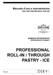
Istruzioni�per�l'utilizzatore
User�Instruction
Instructions�pour�l'utilisateur
Benutzeranleitungen
ARMADIO REFRIGERATO
REFRIGERATED CABINET
ARMOIRE REFRIGEREE
KÜHLSCHRANK
MAGNUM
MAG.06
Capitolo 1 NORME ED AVVERTENZE GENERALI
Section 1 STANDARDS AND GENERAL WARNINGS
Chapitre 1 NORMES ET AVERTISSEMENTS GENERAUX
Kap. 1 NORMEN UND ALLGEMEINE HINWEISE
1.1
MAG.06
DICHIARAZIONE DI CONFORMITA' - DECLARATION OF CONFORMITY
DECLARATION DE CONFORMITE - KONFORMITÄTSERKLÄRUNG
DICHIARAZIONE CE DI CONFORMITA'
CE DECLARATION OF CONFORMITY
DECLARATION CE DE CONFORMITE
KONFORMITÄTSERKLÄRUNG
NOI - THE COMPANY - NOUS - DIE FIRMA
EVERLASTING S.R.L. - Fabbrica Frigoriferi Industriali
S.S. Cisa km. 161 - 46029 SUZZARA ( MN ) - ITALIA
Dichiariamo sotto la nostra esclusiva responsabilità che il prodotto
Declares, under its own sole responsibility, that the product designated
Déclarons sous notre responsabilité exclusive que le produit
Erklärt unter der eigenen und ausschließlichen Verantwortung, daß das Produkt
ARMADIO REFRIGERATO
REFRIGERATED CABINET
ARMOIRE REFRIGEREE
KÜHLSCHRANK
Numero di serie
Serial number
Numéro de série
Seriennummer
al quale questa dichiarazione si riferisce è conforme alle seguenti direttive europee:
to which the present declaration refers, complies with the following european directives:
auquel cette déclaration se rapporte, est conforme aux dispositions européennes suivantes:
auf das sich diese Erklärung bezieht, den folgende europäische Richtlinien entsprechen:
"Macchine" 2006/42/CE
"Bassa tensione" 2006/95/CEE e successive modificazioni
"Compatibilità elettromagnetica" 2004/108/CEE e successive modificazioni
"Materiali ed oggetti destinati a venire in contatto con i prodotti alimentari" 89/109/CEE
"Direttiva 97/23/CE" (PED - Pressure Equipment Directive) apparecchi in classe 1
"Machines" 2006/42/CE
"Low voltage" 2006/95/EEC and subsequent modifications
"Electromagnetic Compatibility" 2004/108/EEC and subsequent modifications
"Materials and objects designed to come into contact with foodstuff" 89/109/EEC
"Directive 97/23/EC" (PED - Pressure Equipment Directive) appliances in class 1
"Machines" 2006/42/CE
"Basse Tensions" 2006/95/CEE et modifications successives
"Compatibilité Electromagnétique" 2004/108/CEE et modifications successives
"Matériels et objets destinés à entrer en contact avec des produits alimentaires" 89/109/CEE
"Directive 97/23/CE" (PED - Pressure Equipment Directive) appareils en class 1
"Maschinen" 2006/42/CE
"Niaderspannung" 2006/95/EG und nachfolgende Änderungen
"Elektromagnetische Verträglichkeit" 2004/108/EG und nachfolgende Änderungen
"Zum Umgang mit Nahrungsmitteln bestimmte Materialien und Gegenstände" 89/109/EG
"Richtlinie 97/23/EG" (PED - Pressure Equipment Directive) Geräte in Klasse 1
La persona autorizzata a costituire il fascicolo tecnico è Paolo Guidetti, legale rappresentante della ditta
EVERLASTING S.R.L. S.S. CISA KM 161 – 46029 SUZZARA (MN) – ITALIA, sede presso la quale è anche custodito.
The person authorized to constitute the technical file is Paolo Guidetti, legal representative of the Company
EVERLASTING S.R.L. S.S. CISA KM 161 – 46029 SUZZARA (MN) – ITALY, where the file is kept.
La personne autorisée à constituer le dossier technique est Paolo Guidetti, représentant légal de la société
EVERLASTING S.R.L. S.S. CISA KM 161 – 46029 SUZZARA (MN) – ITALIE, ou le dossier est conservé.
Die Person die berechtigt ist die technische Unterlagen zusammenzustellen ist Paolo Guidetti, gesetzlicher Vertreter der Firma
EVERLASTING S.R.L. S.S. CISA KM 161 – 46029 SUZZARA (MN) – ITALIEN, wo die Datei gehalten wird.
Suzzara
................................
.........................................
2
ITALIANO
MAG.06
Capitolo 8 ISTRUZIONI PER L’UTILIZZATORE
Le informazioni contenute in questo capitolo sono destinate all’utilizzatore oppure a personale non specializzato (vedi par. 1.3 Manuale
d’uso e manutenzione).
Una volta installata, secondo le istruzioni di cui al cap. 3 (vedi Manuale d’uso e manutenzione), la macchina è da considerare pronta
all’uso.
8.1 COMANDI
Secondo i modelli la macchina sarà fornita di combinazioni diverse di comandi:
8.1.1 Descrizione dei comandi e pulsanti (fig.10)
Il pannello di comando è un termoregolatore digitale per il freddo.
E’ provvisto di 6 pulsanti con funzioni specifiche:
• Display (11) visore di temperatura e dello stato della macchina.
• Tasto on standby (1) se premuto per 5 secondi si accende il termoregolatore.
• Tasto set (13) se premuto accede alla regolazione del set di lavoro della macchina.
• Tasto up (6) se premuto consente l’incremento dei valori, (temp. più alta o valori, in fase di programmazione più alti). Se premuto
segnala sul display la presenza di un allarme HACCP indicando RLS.
• Tasto down (5) se premuto consente la diminuzione dei valori (temp. più bassa o valori, in fase di programmazione più bassi). Inoltre
se premuto per oltre 2 secondi accede al sotto menù di visualizzazione sonde di temperatura e visualizzazione allarmi
HACCP, e conteggio ore di funzionamento compressore, regolazione orologio interno. Se premuto per 10 secondi si avvia la funzione
overcooling (superfreddo).
• Tasto defrost (16) premuto attiva uno sbrinamento manuale.
• Tasto luce (17) premuto attiva la luce interna.
Tutti i tasti se premuti hanno anche la funzione di tacitare il buzzer d’allarme del termoregolatore e memorizzare l’allarme in corso.
8.1.2 Allarmi e segnalazioni (fig.10)
Tutti gli allarmi generano sul termoregolatore, oltre all’accensione del buzzer d’allarme e del led 7, delle segnalazioni per indicare
il tipo d’allarme. Sul display apparirà:
• Pr1 per sonda vano refrigerato guasta.
• Pr2 per sonda evaporatore guasta.
• Pr3 per sonda condensatore guasta.
• COH per condensatore surriscaldato.
• CSd allarme compressore bloccato.
• DFd allarme sbrinamento concluso per durata massima.
• AL allarme di minima temperatura superato.
• AH allarme di massima temperatura superato.
• PF allarme interruzione dell’alimentazione elettrica.
• Rtc errore orologio interno (programmare ora e data nuovamente).
• RLs segnala la presenza di un allarme HACCP registrato.
• LS cartella allarmi HACCP.
Sul termoregolatore inoltre compaiono le seguenti segnalazioni di funzioni in atto:
• led ON/STANDBY (20) acceso quando l’armadio è alimentato ma fermo in standby.
• led COMP (10) indicatore acceso quando il compressore è in funzione, lampeggiante per ritardo alla partenza o protezione attivata.
• led FAN (8) indicatore acceso quando la ventola evaporatore è in funzione.
• led DEF (9) indicatore acceso durante lo sbrinamento.
• led ALL (7) acceso per allarme di temperatura e sonde guaste.
• led HACCP (14) acceso o lampeggiante segnala una memorizzazione allarme HACCP.
Sul termoregolatore inoltre compaiono le seguenti segnalazioni di funzioni in atto:
• led CH (15) (chiave inglese) acceso o lampeggiante segnala una richiesta di manutenzione programmata, per ore di funzionamento
compressore.
• led OVERCOOLING (18) se acceso è in funzione lo stato super freddo.
• led LI (19) acceso quando la luce interna è in funzione.
3
ITALIANO
MAG.06
8.2 INDICAZIONI RELATIVE ALL’USO
8.2.1 Avviamento
Prima di effettuare l’avviamento è necessario verificare che il collegamento elettrico e l’allacciamento siano stati realizzati come
previsto nel par. 3.3 e 3.4. Manuale d’uso e manutenzione. E’ inoltre necessaria una pulizia preliminare secondo le modalità descritte
nel par 5.2.1. Manuale d’uso e manutenzione.
Sequenza d’avviamento (fig.10)
• premere il tasto on-standby per 5 secondi, il display si accenderà
• attendere che il pannello di comando cessi di lampeggiare
• regolazione dell’orologio interno sull’ora attuale.
La prima operazione è la regolazione dell’orologio interno all’ora attuale così come segue: premere il tasto down per 2 secondi il
display visualizzerà rtc (real time clock) premere il tasto set, il display visualizzerà yy (anno). Premere up o down per modificarlo, poi
premere set, il display visualizzerà nn (mese). Premere up o down per modificarlo, poi premere set, il display visualizzerà yy (giorno).
Premere up o down per modificarlo, poi premere set, il display visualizzerà hh (ora). Premere up o down per modificarlo, poi premere
set, il display visualizzerà nn (minuti). Premere up o down per modificarlo poi premere set. Terminata la regolazione non operare sullo
strumento per 60 secondi, automaticamente uscirà dalla procedura.
8.2.20 Modi d’arresto (fig.10)
• premere il tasto on-standby (1) per 5 secondi, il display si spegnerà.
8.2.3 Messa a punto e regolazione
La macchina è impostata, dalla fabbrica per funzionare alle seguenti temperature:
• gamma TNV
(temperatura normale ventilata)
2°C
• gamma TNBV (temperatura normale bassa, ventilata)
0°C
• gamma BTV
(bassa temperatura, ventilata)
-20
• gamma TN-.PE (temperatura normale pesce)
-5
Se l’utilizzatore vuole operare in condizioni di temperatura diverse da quella impostata, deve agire come segue:
Comando elettronico (fig.10)
Termoregolatore
• Premere SET (13) e rilasciare, sul display, se non sono presenti allarmi apparirà la temperatura impostata.
• Per incrementare la temperatura agire sul tasto UP (6) entro 5 secondi.
• Per abbassare la temperatura agire sul tasto Down (5) entro 5 secondi.
• Lo strumento memorizza automaticamente l’ultimo valore di temperatura impostato.
8.2.4 Sbrinamento automatico e manuale
• La macchina è impostata, dalla fabbrica, per effettuare lo sbrinamento automatico ad intervalli prestabiliti come segue:
• gamma TNV (temperatura normale ventilata) uno sbrinamento di tipo “per fermata del compressore” di durata max 30 minuti ogni
8 ore di funzionamento.
• gamma TNBV (temperatura normale bassa, ventilata) uno sbrinamento tipo “ad attivazione resistenze elettriche” di durata max 30
minuti ogni 8 ore di funzionamento.
• gamma BTV (bassa temperatura, ventilata) uno sbrinamento tipo “ad attivazione resistenze elettriche” di durata max 30 minuti ogni
6 ore di funzionamento del compressore.
• gamma TN-PE (temperatura normale pesce) uno sbrinamento tipo “ad attivazione resistenze elettriche” di durata max 30 minuti
ogni 6 ore di funzionamento.
E’ possibile impostare altre modalità di sbrinamento quali: (a tempo di funzionamento compressore, a temperatura evaporatore, ad
orario prestabilito). Per modificare le modalità di sbrinamento vedere il libretto del termoregolatore allegato.
L’utilizzatore può effettuare uno sbrinamento manuale, secondo le proprie necessità, agendo come segue: (fig10)
• premere per oltre 5 secondi, il tasto UP (defrost) (6)
durante il ciclo di sbrinamento automatico e manuale il led DEF rimarrà acceso, al termine del ciclo di sbrinamento l’indicatore si
spegne e la macchina riprende automaticamente il ciclo normale di funzionamento.
Capitolo 9 HACCP
9.1 HACCP
Per rispondere ai requisiti minimali imposti dalle normative HACCP il termoregolatore è in grado di memorizzare fino a 3 allarmi
HACCP. Lo strumento fornisce le seguenti informazioni:
• valore critico di temperatura.
• la data e l’ora reale di registrazione dell’allarme.
• durata dell’allarme (da 1min a 99h e 59min, parziale se l’allarme è in corso).
I valori critici impostati dei parametri sotto riportati sono modificabili per utilizzi diversi e sono contenuti nel menù di programmazione
del termoregolatore. Per modificare tali valori vedere il libretto allegato del termoregolatore.
Parametro
A1
A4
A6
A7
Descrizione
Temperatura HACCP minima
Temperatura HACCP massima
Tempo di ritardo all’accensione
Tempo fuori range temperatura
TNSV
-5
15
120
15
4
TNBV
-5
15
120
15
TN-PE
-10
15
120
15
BTV
-30
-5
120
15
ITALIANO
MAG.06
9.2 Funzionamento memorizzazione HACCP
Quando il valore di temperatura misurata dalla sonda del vano refrigerato fuoriesce dal limite minimo (A1) o da quello massimo (A4),
per un tempo superiore a (A7) viene segnalato un allarme e automaticamente generata una cartella LS nel menù “stato macchina”
del termoregolatore. Nella cartella generata vi sono contenuti il valore di temperatura massimo o minimo raggiunto e il tempo di
allarme in corso o registrato.
9.2.1 Visualizzazione allarmi HACCP
Gli allarmi memorizzati dal termoregolatore sono visibili come segue:
• premere il tasto down (5) per 2 secondi il display visualizzerà la prima label disponibile.
• premere il tasto up (6) o down (5) per selezionare la label LS (cartella contenente gli allarmi).
• premere il tasto set (13), il display visualizzerà il tipo di allarme HACCP (AL, AH).
• premere nuovamente il tasto set (13) per visualizzare in sequenza il valore di temperatura d’allarme, la data e ora reale di registrazione dell’allarme e la durata dello stato di allarme.
Esempio
AH1
Allarme di massima superato
Sta
Il display sta per visualizzare la data e l’ora in cui è intervenuto l’allarme
n (09)
Mese di registrazione allarme
20
y (09)
Temperatura critica
Anno di registrazione allarme
d (15)
Giorno di registrazione allarme
h (16)
n (30)
Ora di registrazione allarme
Minuti di registrazione allarme
Dur
Il display sta per visualizzare la durata dello stato d’allarme
n (30)
Minuti di durata stato d’allarme
h (2)
Ore di durata stato d’allarme
Nell’esempio sopra riportato il termoregolatore ha registrato un allarme di superamento massima temperatura (AH1) a 20°C il 15
settembre 2009 alle ore 16.30 è restato in stato d’allarme 2 ore e 30 minuti.
Per uscire dalla visualizzazione allarmi HACCP premere il tasto ESC (12) o non operare su alcun tasto per 15 secondi.
9.2.2 Cancellazione dell’elenco degli allarmi HACCP
Per cancellare la cartella allarmi operare come segue:
• premere il tasto down (5) per 2 secondi.
• premere il tasto up o down per selezionare la label rLS.
• premere set (13), visualizzerà 0.
• premere il tasto up (6) entro 15 secondi per impostare il valore 149.
• premere set (13) e non operare per 15 secondi.
il display visualizzerà ------ lampeggiante per 4 secondi e l’icona HACCP si spegnerà. Se non vi è alcun allarme in memoria la label
rLS non verrà visualizzata. Se non si cancellerà la cartella allarmi, un nuovo allarme HACCP sovrascriverà quello precedente.
Capitolo 10 MANUTENZIONE PROGRAMMATA
10.1 Conteggio delle ore di funzionamento compressore
Lo strumento è in grado di memorizzare fino a 9999 ore di funzionamento compressore, per programmare una manutenzione dopo
le ore stabilite dal parametro C10. Alla scadenza delle ore programmate si accenderà l’icona 15 (chiave inglese) sul display.
10.1.1 Per visualizzare le ore di funzionamento compressore procedere come segue:
• premere per 2 secondi il tasto down (5), il display visualizzerà la prima label disponibile.
• premere il tasto up (6) o il tasto down (5) per selezionare CH.
• premere set, il display visualizzerà le ore di funzionamento compressore.
Per uscire dalla procedura premere set (13) e non operare per 15 secondi.
10.1.2 Per cancellare le ore di funzionamento compressore procedere come segue:
• premere il tasto down (5) per 2 secondi, il display visualizzerà la prima label disponibile.
• premere il tasto up (6) o il tasto down (5) per selezionare rCH.
• premere set (13), il display visualizzerà 0.
• premere il tasto up (6) ed impostare 149.
• premere set (13) e non operare per 15 secondi il display visualizzerà ----- lampeggiante per 4 secondi e le ore saranno azzerate.
Per maggiori istruzioni riguardo il funzionamento del termoregolatore vedere il libretto allegato.
5
ENGLISH
MAG.06
Section 8 USERS INSTRUCTIONS
The information in this section regards the user or other non-specialized personnel (see section 1.3 Instruction and maintenance
manual).
After installed according with the instructions of section 3 (see Instruction and maintenance manual) the machine is ready for use.
8.1 CONTROLS
According to the models, the appliance is equipped with different types of controls:
8.1.1 Description of controls and keys
The control panel is a digital control thermoregulator for low temperature .
And is provide with 6 keys with the following specific functions:
- Display (11), to check temperature and operation of the machine.
- Stand By key (1) if pressed for 5 seconds light on the thermoregulator
- Set key (13) if pressed allows the regulation of the working set of the Machine
- Up key (6), allows the increasing of the values, (higher temperature or higher values during the highest
Programming phase) if pressed, signs on the display un alarm HACCP indicated has RLS.
- Down Key (5) if pressed allows the decrease of the values (lower temperature or lower values during
programming phase).Moreover, if pressed for more than 2 seconds accede directly to the under menu of
probes temperature, alarm HACCP visualization, compressor working hours and regulation of the internal
watch. At last, if pressed for more than 10 seconds it starts the overcooling function.
- Defrosting key (16) for the manual defrosting
- Light key (17) for internal lights.
All the keys if pressed have also the function of silencing the buzzer of the thermoregulator and memorized the possible alarms.
- AL1 alarm for low temperature inside the refrigerated room
- AH3 alarm for too high condensing temperature
- HC1…8 alarm for highest temperature reached out of the HCCCP limits
- tC1…8 time that passed from temperature out of the limits
- bC1…8 black out alarm with recording of the temperature at the time of the event
- bt1…8 time that passed from black out with temperature over the HCCP limits
8.1.2. Alarms and signals (Fig.10)
All the alarms produce on the thermoregulator besides the lighting of the buzzer and led 7, signals that show the type of alarm.
The display will indicate:
- Pr1 faulty refrigerated ambient probe
- Pr2 for faulty evaporator probe
- Pr3 for faulty condenser probe
- COH overheated condenser
- CSd compressor block alarm
- DFd end of defrosting with max. cycle
- AL alarm for low temperature overhead
- AH alarm for highest temperature overhead
- PF interruption of the electrical power supply
- Rtc wrong internal watch, ( programme date and hour )
- RLS signal for noticed alarm of HACCP .
- LS folder for HACCP alarm
6
ENGLISH
MAG.06
Moreover, on the thermoregulator appear the following signals for functions in progress:
- ON/STANDBY Led (20), turn on when the machine is connected but in stand by.
- COMP led (10) lights steadily when the compressor is running, blinks in case of starting delay or when protection is active
- FAN led (8) lights steadily when the evaporator fan is working
- DEF led (9) lights steadily during defrosting cycle.
- ALL led (7) lights steadily for alarm of temperature and probe faulty.
- HACCP led (14) lights steadily or intermittent to signalized alarm of an HACCP memorized.
In the thermoregulator appears the followings signals for functions in progress:
-CH led (15) (adjustable wrench) lightly or intermittent signalize a request of program maintenance for the compressor working
hours.
- OVERCOOLING led (18) lightly for overcooling function.
- LI led (19) lightly wend internal light on.
8.2.1. Start-up
Before starting up the machine check that the electrical connections have been made correctly as indicated in sections 3.3 and 3.4
of Instruction and maintenance manual. Moreover, it is necessary to perform a preliminary cleaning of the machine as described in
section 5.2.1 Instruction and maintenance manual.
Starting sequence (picture.10)
- press on –stand by for 5 seconds, display light up
- wait until the display stop blinking
- set the internal watch with the actual hour
The first step to do is the regulation of the internal watch in the following way
- press the down key for 2 seconds, the display will evidence rtc (real time clock), press the set key and the display will evidence yy
(year ), press up or down to change it and than press set.
The display will showup nn (month) , press up or down to change it, than press set.
The display will show up yy (day) press up or down to change it, than press set.
The display will show up hh(hour) press up or down to change it, than press set.
The display will showup nn (minutes) press up or down to change it , than press set.
At the end of the complete set up do not operate in the tool for 60 seconds, automatically you came out of the process.
8.2.20 Arrest ways (picture 10)
. positioned the general key (1) in the position -08.2.3 Set-up and adjustment
The machine is set for work at the following temperature:
- TNV range
(normal temperature, air cooled ) 2° C
- TNBV range
(low temperature, air-cooled)
0° C
- BTV range
(low temperature air -cooled)
-20°C
-TN-PE range
(normal temperature for fish)
-5° C
If the user intends to use temperatures different from the factory set he must proceed as follows:
Electronic controls (pickture.10):
Thermoregulator
- press SET (13) and release, if there aren’t any alarms the display shows label “SET”; press again to display the set
temperature
- to increase the temperature press UP key (6) within 5 seconds
- to decrease the temperature press DOWN key (5) within 5 seconds
The instrument saves automatically the last temperature value programmed.
8.2.4 Automatic and manual defrosting
The machine is set for automatic defrosting at intervals as described below:
- TNV range (normal temperature, air-cooled) one defrosting cycle by compressor stopped
lasting max. 30 minutes, each 8 hours of the compressor working.
- TNBV range (normal low temperature, air-cooled) one defrosting cycle with “activation of electric heating elements”,
lasting max. 30 minutes, each 8 hours of compressor working.
-BTV range ( low temperature, air-cooled) one defrosting cycle with “activation of electric heating elements”,
lasting max. 30 minutes, each 6 hours of compressor working.
- TN-PE range (normal temperature for fish) one defrosting cycle with “warm gas ”, lasting max. 30 minutes, every 6 hours of the
compressor working. To change the modalities of defrosting method see the termoregulator manual in attachment.
If the user wants to make a manual defrosting, in accordance with effective requirements he must proceed as follows:
- press UP key (DEFROST) (6) for more than 5 seconds
- during the automatic defrosting cycle DEF led lights steadily, at the end of the defrosting cycle the DEF led will switch off and the
machine automatically resumes a normal operating cycle.
7
ENGLISH
MAG.06
Section 9 HACCP
9.1 HACCP
To answer the minimum requirements fixed by the HACCP regulations the thermoregulator has some parameters that save and store
until 3 HACC alarms. The tool release the following information’s :
- critical value of temperature
- date and real time of alarm registration
- during of the alarm (from 1 until 99h e 59 min., (partial if alarm in progress)
The values of the parameters under brought, are possible and changeable for different uses and they are contained in the program
menu of the termoregulator.
To change the values see manual of termoregulator in attachment.
Parameter
Description
A1
HACCP lowest temperature
A6
time of delay to the lighting t
A4
A7
HACCP highest temperature
TNSV
TNBV
TN-PE
BTV
-5
-5
-10
-30
120
120
120
15
120
Time out of
15
15
15
15
15
-5
15
9.2 Function and memorization HACCP
When the value of the temperature measured by the probe of the refrigerated zone becomes out of the minim or max. limit (A1)/
(A4), for an overhead time out of range (A7), it will appears an alarm signal and create automatically a folder LS in the “conditions
machine” menu of the thermoregulator. The same folder contains the highest and lowers value of temperature reached and the time
of the alarm in progress registered.
9.2.1 Display of the memorized alarms
The alarms generated by the termoregulator are displayed as follows:
- press down key (5), for 2 seconds, display will show the first label available
- press up key (6) or down (5) to select the LS label (alarms folder)
- press set key (13), the display will evidence the type of alarm HACCP (AL,AH)
- press once more the key (13) to see the value of temperature and during of the alarm, moreover date and real time of the alarm
registration and conditions in progress.
Example
AH1
20
Sta
y (09)
n (09)
d (15)
h (16)
n (30)
Dur
h (2)
n (30)
Max value Allarme superadded
Critical temperature
Viewer of date and hour of the alarm
Year of alarm registration
Month of the alarm registration
Day of the alarm registration
Hour of the alarm registration
Minute of the alarm registration
Viewer of the alarm progress during
Hour of the alarm progress during
Minutes of alarm progress during
In the above example, the termoregulator registered un alarm of overheads the values of highest temperature (AH1) from 20°C the
15th of September 2009 at 04.30 pm and the same alarm had the during of 2 h and 30minuts..
To the exit of the alarm HACCP visualisation press key ESC (12) or don’t operate in any other key for 15 seconds.
9.2.2. Reset of the HACCP alarm list
To reset the alarm folders proceed in the following way:
- press key down (5) for 2 seconds
-press key up or down to select label rLS
-press set (13), and see 0
-press key up (6) within 15 minutes to set the value 149
-press set (13) and don’t act any other operation kind for 15 seconds
The display will show ------in intermittence for 4 seconds and the icon HACCP will turn of. If there isn’t any other kind of alarm in
memory, the label rLS will not be show up. If the alarm folder will not be delete a new HACCP alarm will substitute the precedent
one.
8
ENGLISH
MAG.06
CAP. 10 PROGRAM MAINTENANCE
10.1 Compressor working hours
The tool is able to memorized until 9999 of the compressor working hours, to program the maintenance operation in concomitance
with the estimate hours in the C10 parameter. At the expiring of the programmed hours the icon 15 will light up 15 ( wrench) on the
display.
10.1.1 To take vision of the compressor working hours proceed has following:
- press for 2 seconds the down key (5) and in the display will be in evidence the first label available
- press key up (6) or down key (5) to select rCH
- press set, and the display will evidence the working hours of the compressor
To exit press set (13) and don’t operate for the next 15 seconds.
10.1.2 To delete the working hours of the compressor proceed in the following way:
- press for 2 seconds the down key (5) and in the display will be in evidence the first label available
- press key up (6) or down key (5) to select rCH
- press set (13), he display will evidence 0
-press up key ( 6)and input 149
- press set (13) and don’t operate for the next 15 seconds, the display will evidence ------blinking for 4 seconds and the value of the
hours will be delete.
For more instructions regarding the termoregulator function see the manual in attachment.
9
MAG.06
Modello - Model - Modèle - Modell
815
1500
700
815
700
2100
2100
MAGNUM 80-700
MAGNUM 80-1500
750
peso del materiale
imballato ( kg )
shipping weight ( kg )
poids du matériel
emballé ( kg )
Gewicht verpackte
Geräte ( kg )
�
ingombri del materiale imballato
Dimensions of packed material
encombrements du matériel emballé
Abmessungen verpackte Geräte
�
TABELLA 1
TAV. 1
TABLEAU 1
TABELLE 1
�
modello - model - modèle - Modell
�
cartone
cadboard
carton
Karton
�
�
�
gabbia / cassa
crate/case
cage / caisse
Lattenverschlag/Holzkiste
�
�
�
�
peso
unitario
unit
weight
poids
unitaire
Einheit
cartone gabbia
gewicht
c.board crate
�
carton
cage
Karton Latten
�
�
��
cassa
case
caisse
Holzki
�
volume
depos.
storage
volume
volume
dépôt
Lager
volumen
�
���
fluido
refrigerante
refrigerant type
fluide frigorigène
Kältemittel
potenza
power
puissance
Leistung
�
�
resa
assorb.
output
absorb.
fournie
absorb.
Abgabeleis. aufgenomm.
�
�
������
������
tipo
type
type
Typ
�
�
�
�
������
MAGNUM
MAGNUM
MAGNUM
MAGNUM
MAGNUM
MAGNUM
MAGNUM
MAGNUM
MAGNUM
MAGNUM
MAGNUM
MAGNUM
MAGNUM
MAGNUM
701/2
701/2
701/2
1502/3/4
1502/3/4
702 2T
702 2T
702 2T
1502 2T
1502 2T
1502 2T
1503 2T
1503 2T
1503 2T
TNSPE
TNBV
BTV
TNBV
BTV
TNBV
BTV
TNS PE
TNBV
TNS PE
BTV
TNBV
TNS PE
BTV
830
830
830
1580
1580
830
830
830
1580
1580
1580
1580
1580
1580
2180
2180
2180
2180
2180
2180
2180
2180
2180
2180
2180
2180
2180
2180
895
895
895
895
895
895
895
895
895
895
895
895
895
895
910
910
910
1640
1640
910
910
910
1640
1640
1640
1640
1640
1640
2310
2310
2310
2310
2310
2310
2310
2310
2310
2310
2310
2310
2310
2310
935
935
935
935
935
935
935
935
935
935
935
935
935
935
155
150
155
225
235
220
220
220
310
310
310
300
300
300
162
157
172
232
242
227
227
227
317
317
317
317
317
317
195
195
205
270
290
272
272
272
362
362
362
362
362
362
225
225
235
305
325
307
307
307
397
397
397
387
397
387
625
625
625
1365
1365
300
300
300
625
625
625
966
300
300
830
830
550
1210
823
590
500
590
830
830
550
830
830
550
400
400
570
510
870
320
490
300
400
400
570
400
400
570
R 404A
R 404A
R 404A
R 404A
R 404A
R 404A
R 404A
R 404A
R 404A
R 404A
R 404A
R 404A
R 404A
R 404A
300
300
400
340
500
310
340
300
300
300
400
300
300
400
MAGNUM
MAGNUM
MAGNUM
MAGNUM
701
701
1502
1502
TNV
BTV
TNV
BTV
830
830
1580
1580
2180
2180
2180
2180
895
895
895
895
910
910
1640
1640
2310
2310
2310
2310
935
935
935
935
150
160
225
225
157
167
242
242
195
205
270
270
225
235
305
305
625
625
1365
1365
830
550
1210
823
450
670
610
1050
R 404A
R 404A
R 404A
R 404A
300
400
340
500
10
MAG.06
Legenda componenti
CP
IP
LI
MS
RC
RE
RP
RS
Pb1
Pb2
Pb3
S
-
Moto-compressore
Interruttore porta
Luce interna
Morsettiera alimentazione
Resistenza scarico
Reattore
Resistenza anticondensa
Resistenza sbrinamento
NTC
NTC
Sonda condensatore NTC
Starter
UR
VC
VE
List of components
- Unità remota
- Ventilatore condensatore
- Ventilatore evaporatore
CP
IP
LI
MS
RC
RE
RP
RS
Pb1
Pb2
Pb3
S
Legenda colori
MA
-
Marrone
BL
-
Blu
BI
-
Bianco
-
Motor compressor
Door microswitch
Interior light
Power supply terminal board
Drain resistance
Reactor
Anti-condensate resistance
Defrost resistance
NTC
NTC
Sensor condensator NTC
Starter
Légende des composants
MA
-
Brown
BL
-
Blue
BI
-
White
Tabelle Teilebeschreibung
UR VC VE -
Group à distance
Ventilateur condenseur
Ventilateur évaporateur
CP
IP
LI
MS
RC
RE
RP
RS
Pb1
Pb2
Pb3
S
Bleu
BI
-
Blanc
VE/RP
Marron
-
LI
-
BL
Pb1
MA
RS/RC
Légende des couleurs
Pb2
Remote unit
Condenser fan
Evaporator fan
Colour code
-
UR VC VE -
Motorverdichter
Türschalter
Innenlicht
Klemmenleiste Versorgung
Ablaßwiderstand
Reaktor
Heizwiderstand
Abtauwiderstand
NTC
NTC
Sensor Kondensator NTC
Starter
MA
-
Braun
BL
-
Blau
BI
-
Weiß
IP
1 2 3 4 5 6 7 8
N1 K4
K3
N0
BL
MA
230/50Hz
MS
N1 K3NC N1 K2 N L N1 K1
COLLEGAMENTO
TTL/MODBUS
11
Entfernt installierte Einheit
Verflüssigergebläse
Verdampfergebläse
Tabelle Farben
CP
Motocompresseur
Interrupteur porte
Lumière intérieure
Bornier alimentation
Résistance évacuation
Ballaste
Résistance anti-eau de condensation
Résitance dégivrage
NTC
NTC
Sonde condensator NTC
Starter
Pb3
CP IP LI MS RC RE RP RS Pb1 Pb2 Pb3 S -
UR VC VE -
MAG.06
14
MAG.06
15
EVERLASTING s.r.l.
46029 SUZZARA (MN) - ITALY - S.S. Cisa km.161
Tel.0376/521800 (4 linee r.a.) - Telefax 0376/521794
http://www.everlasting.it - E-mail:[email protected]