1
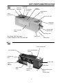
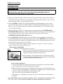
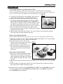
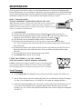
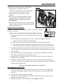
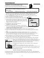
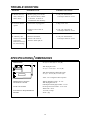
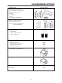
PERI-PRO III INTRA-ORAL FILM PROCESSOR USER’S MANUAL CONGRATULATIONS Since 1977, more than 70,000 Peri-Pro processors have been manufactured and sold by Air Techniques, making it the processor of choice for the dental profession. This latest version, the Peri-Pro III, retains the same proven rollerless transport system as earlier models. This unique system carefully guides the film through the developing process without the image surface being touched. The Peri-Pro III also offers the same slim space saving design, with or without a daylight loader, convenient for small office spaces. Where the new Peri-Pro III differs from previous models is in design features that make maintenance and operation easier and faster. The Peri-Pro III processes film, dry-to-dry and ready to read, in only 5 minutes. To ensure the delivery of consistent film quality, a new heating pad system, located under the tanks, maintains uniform chemistry bath temperature. The most significant new design features of the Peri-Pro III are an external water drain valve in the base and a refill access door built right into the cover. With these new features, the daily maintenance task of draining and replacing the wash water is accomplished in a few minutes without removing the processor cover. Just turn the valve to drain the water, open the refill access door, close the valve, and refill the water tank using the Peri-Pro III water bottle. By following the Maintenance procedures detailed in this manual, you can depend on years of reliable service from your Peri-Pro III processor. TABLE OF CONTENTS Installation Key Parts Identification ..........................................................................................3 Box Contains / Unpack ...........................................................................................4 Install & Assemble Processor .................................................................................4-5 Operation Operator Controls ....................................................................................................5 Processing film ........................................................................................................6-7 Maintenance Daily ........................................................................................................................8 Every Two Weeks ....................................................................................................8-9 Quarterly ..................................................................................................................10 Trouble Shooting .........................................................................................................11-14 Specifications / Dimensions ........................................................................................14 Accessories ...................................................................................................................15 2 KEY PARTS IDENTIFICATION FIG. 1 TABS FOR CARRIERS FILM INLET GRILL FILM INLET SHUTTER FILM PACKET STORAGE COVER ASSEMBLY MAINTENANCE LABEL TRASH RECEPTACLE AIR OUTLET GRILL OPERATOR CONTROLS FILM DELIVERY RECEPTACLE REFILL ACCESS PANEL AIR INLET GRILL Not shown: Grill inlet cover comes installed on the Film Inlet Grill DRAIN VALVE DRAIN HOSE FIG. 2 DRYER TRANSPORT FILM TRANSPORT PCB & TRANSFORMER COVER THERMISTOR ARM 5 AMP FUSE DEVELOPER TANK (BLACK) AIR HOLES FIXER TANK (RED) WASH TANK (WHITE) 3 DRYER HEATING ELEMENT ACCESS PANEL INSTALLATION SHIPPING BOX CONTAINS: UNPACK q Water bottle with flexible neck attachment 1. Remove the water bottle and flexible neck attachment from the cardboard packing found at one end of the box. 2. Place one hand on each side and underneath the processor. Lift the processor out of the carton and place it on a flat surface. Remove the end caps and plastic bag. 3. Remove the processor cover and set aside. 4. Remove the accessory boxes and retain for future use. Remove the top packing foam. 5. Pull the cardboard insert out of the dryer rack and set aside; lift the transport out (the transport cannot be removed until the card board insert is removed first). 6. Remove the shipping foam from the back wall of the processor. 7. Remove the foam cleaning pads from the chemistry tanks and set aside. 8. Do not remove the clips holding the water drain tube to the perimeter of the base. 9. Set the base on a flat, level, stable counter. Important: The surface must be stable so that q Peri-Pro III Processor base with cover Note: Grill Inlet Cover comes installed on the Film Inlet Grill Inside the processor: q Film transport q Chemistry tanks (Black developer tank; red fixer tank; white water tank) q Accessory boxes (3) containing: # 90850 - 3 ea. Pedo (#0) Film Carrier 2 ea. Bite-wing Film (#3) Carrier # 90825 - 3 ea. Anterior Film (#1) Carrier 1 ea. Occlusal Film (#4) Carrier # 90840 - Film receptacle with 3 dividers q Literature kit: Manual, Warranty card INSTALL PROCESSOR 1. Fill Tanks The tanks can be installed in or removed from the base only when the film transport is out of the processor. If you installed the transport after unpacking, remove it now. Follow the tank installation and chemistry filling sequence below to prevent contamination of chemistry due to accidental spilling or splashing. Fixer in the developer tank will cause contamination. Peri-Pro chemistry should be at or below 75°F. q Locate the thermistor arm above and to the left of the developer FIG. 3 (black) tank. Carefully lift the arm up, using the finger hole, until it locks in place. See Fig. 3. q Remove all three tanks and rinse. Note: The wash tank requires some effort to remove the drain stem with the O-Ring from the drain receptacle. q Install the wash tank on the right side of the base, making sure the drain stem with the O-ring seats in the drain receptacle by pushing down until the tank’s feet rest on the floor of the base. Fill the Peri-Pro III water bottle to the Fill Line (40 oz.) with room temperature water (70° - 80°F). Attach the flexible neck to the bottle and flex into position. Empty entire contents into the water tank. q Install the fixer tank next to the water tank, and fill with contents of the fixer bottle. Pour carefully to prevent splashing. q Install the developer tank on the left. Fill with the contents of the developer bottle. Lower the thermistor arm into the tank. q If chemistry or water is accidentally spilled beneath the chemistry tanks, remove the tanks and immediately dry the tanks, both sides of the heater plate and the depression in the base and the area around the heater pad. Reverse the procedure to remove. 4 INSTALLATION chemistry does not splash or spill. FIG. 4 2. Assemble Processor q Lower the film transport straight into the tanks. The film transport must sit squarely on the cutouts found on the top of the vertical plates to the left and right side of the tanks. Note: The Transport locks the thermistor into place. q Install the film inlet grill on top of the film transport. Note that it installs one way: track 1 to the rear and track 8 to the front of the processor. q Remove the water drain tube from the clips that hold it to the perimeter of the processor base and push one end of this tube onto the hose barb part of the drain valve at the right end of the processor. Place the other end of the drain tube into a receptacle large enough (at least 45 oz.) to hold the contents of the water tank when it is drained. FIG. 5 q Install the processor cover onto the base with the refill access door in front. q Snap the film dividers (optional installation) into place in the film delivery receptacle. Hang the film delivery receptacle on the cutout at the dryer end of the cover. q Plug the line cord into a 115V outlet. 3. Check Operation of Refill Access Door q Open the refill access door by firmly pinching the two tabs, then pulling the door open. There will be some resistance. q Close the panel by pushing it in until it latches (snaps) shut. OPERATION POWER SWITCH (Amber) When the POWER switch is turned ON it will illuminate, indicating that there is power to the processor and the heating system is on. Turn the POWER switch OFF at the end of the day. See Fig. 6A. POWER switch is left in the ON position and the green READY light is illuminated. See Fig. 6B FIG. 6 FILM INLET SHUTTER POWER READY WHEN LIT PROCESS A B TEMPERATURE READY LIGHT(Green) / PROCESS SWITCH . When chemistry reaches its factory pre-set processing temperature of 75°F, the READY light flashes, then remains steady, indicating that chemistry is at processing temperature. Processing is initiated by turning the PROCESS switch ON. After processing, the PROCESS switch is turned OFF. The Peri-Pro remains ready to process film as long as the closed when processing film. It is closed when it latches, or snaps, shut. See Fig. 1 & 5. REFILL ACCESS DOOR Open the refill access door when changing and refilling water, and to check chemistry levels at the start of the day. This door must be 5 When the shutter is slid to the right, it latches in place. Films drop into the transport and begin processing automatically when the transport arms move into position and the shutter opens. New batches of film can be processed every 55 seconds. FIG. 7 OPERATOR CONTROLS OPERATION PROCESSING FILM Duplicating films exposed in the Peri-Pro Film Duplicator/Daylight Loader are processed in the same manner as regular films. 1. Before processing film, open the refill access door to determine whether chemistry in the developer and fixer tanks are at the Fill Line level as indicated on the inside of the refill access door. If not, top with water to the Fill Line. Close the refill access door. 2. Turn the POWER switch ON. The amber light illuminates, indicating that there is power to the processor, the heating system is on and the chemistry is being heated. Chemistry heats at a rate of about 1°F every two to three minutes. For example: chemistry initially at 65°F will reach set point (75°F) in about 25 minutes. 3. When the chemistry is within 1°F of the pre-set processing temperature, the TEMPERATURE READY/PROCESS light flickers. When the light remains steady, the factory pre-set temperature has been reached and the Peri-Pro III is ready to process film. Only process film when the TEMPERATURE READY/PROCESS light is on . 4. Turn the PROCESS switch ON. (There is no visual indication, only an audible motor sound and warm air blowing out of the air outlet grill when processor is in the PROCESS mode.) Insert film into the film inlet and slide the shutter to the right until it latches. Film is automatically processed. A new batch of film can be processed every 55 seconds. Use the handy removable trash receptacle when stripping covers off film. The trash receptacle is especially useful when using a Daylight Loader. q Processing #2 (Adult) Films #2 films can be fed directly into the processor FIG. 9 a. Strip the cover off a periapical film and place it into any of the eight slots of the inlet grill. All 8 slots can be loaded at the same time if required. Do not put two films into the same slot. b. Slide the shutter to the right until it latches. The films drop into the transport and begin processing when the transport arms automatically move into position and the shutter opens. If a film is bent, straighten it. c. As soon as the shutter moves back into the original closed position, the next batch of films may be loaded into the inlet slots and the process repeated. d. When the last films to be processed are loaded, place the inlet cover over the film inlet. The inlet cover prevents film fogging due to light leaks. If a Daylight Loader is being used, put the inlet cover in place before hands are removed from the cuffs. Note: The inlet cover comes installed on the grill inlet. e. When films have completed the processing cycle, they are delivered into the film delivery receptacle. Note: With dividers in place in the film receptacle, the four compartments correspond to slots I & 2, 3 & 4, 5 & 6, 7 & 8 of the film inlet grill. 6 The dividers separate sets of film pairs. OPERATION PROCESSING FILM q Processing #0 (Pedo) or #1 (Adult Anterior) Films #0 and #1 films cannot be fed directly into the processor. These films fit into corresponding # carriers (supplied with the processor), each of which carries the film through the processing cycle. Up to six #0 or #1 films can be loaded into corresponding carriers at one time. FIG. 10 a. To load #0 or #1 film into the corresponding # carrier, nest the carrier inside the tabs on the cover, next to the inlet grill. b. Strip the cover off the film(s) and slide the film(s) vertically, one at a time, into any of the six grooves on the carrier. Push down firmly until the film touches the cover. Repeat until as many grooves as required are filled. The films should be standing vertically and parallel to each other, away from the center bar. Make sure that each film on the carrier is in its own groove. c. Remove the film inlet grill. (Remember to replace it when processing #2 films.) Insert the carrier, with the film(s) standing vertically, into the film inlet. d. Slide the shutter to the right until it latches. The carrier will drop into the transport and begin processing when the shutter automatically opens. q Processing #3 (Bite-Wing) Films #3 films cannot be fed directly into the processor. Use a #3 carrier that holds two films at a time. a. Strip the cover off one or two #3 film(s) and slide the film(s) horizontally, one at a time, through both side plates of the #3 carrier. Remove film inlet grill. b. Insert the carrier into slots 3 and 6 in the film inlet. Make sure the edges of the film(s) FIG. 11 clear the side walls of the film inlet. c. Slide the shutter to the right until it latches. #3 #0 The carrier will drop into the transport and begin processing when the shutter automatically opens. q Processing #4 (Occlusal) Films a. Strip the cover off one #4 film and carefully bend almost in half. Slide the film into the #4 #1 carrier, making sure both edges of the film are held in place by the guide tabs. Remove film inlet grill. b. Place the carrier onto the film inlet with the orientation arrow (on the side of the carrier) pointing down. c. Slide the shutter to the right until it latches. The carrier will drop into the transport and begin processing when the shutter automatically opens. 5. When processing is completed, turn the PROCESS switch OFF. The green READY light remains lit. At the end of the day turn the POWER switch OFF. Both the green READY light and the amber POWER light will extinguish. 7 MAINTENANCE Servicing your Peri-Pro III on a daily, two week and quarterly basis is critical to maintaining quality processor performance. We recommend the maintenance procedure outlined below, using Formula 2000 cleaner, and Peri-Pro Developer and Fixer, which are specially formulated for Peri-Pro processors. This maintenance schedule may have to be modified if more frequent cleaning is required. DAILY - CHANGE WATER TOP OFF CHEMISTRY TANKS WITH WATER TO FILL LINE Note: Remember to place the wash water drain tube into a receptacle large enough (at least 45 oz.) to hold the contents of the water tank when it is drained. The best location for the receptacle is on the floor. Dispose of wash water in accordance with local codes. 1. Turn POWER OFF. 2. Find the water drain valve handle at the lower right hand corner of the processor base. 3. Open the drain by turning the handle a full 90° clockwise . Allow the water tank to drain completely. If the tank interior appears soiled, rinse tank and drain completely. 4. Close the drain valve by turning the handle a full 90° counterclockwise . 5. Fill the Peri-Pro III water bottle to the Fill Line (40 oz.) with room temperature water (70° - 80°F). Extend the neck of the bottle and flex into position. Empty entire contents into the water (white) tank. 6. Check that the solution in the developer (black) and fixer (red) tanks are up to the Fill Lines as indicated on the inside of the refill access door. If not, top off the developer and fixer tanks with water. 7. Close the refill access door to enable the processing of films. 8. Turn POWER ON to prepare for processing. EVERY TWO WEEKS (or every 300 - 350 films) SCRUB TRANSPORT; CHANGE PERI-PRO CHEMISTRY Caution: Cleaning and changing chemistry requires the removal of the cover and film transport from the Peri-Pro III. Always turn POWER OFF and unplug the line cord before removing the cover or transport. Scrub Transport 1. Turn POWER OFF and unplug the line cord. Remove the film receptacle, lift off the cover. 2 Lift the film transport and let the solutions drip back into the tanks before placing the transport in a sink. (Use of optional Service Tray PN90121 will contain any dripping chemistry.) 3. Rinse the transport thoroughly with warm water to soften residue and dried chemistry. Be sure to rinse above the chemistry level, keeping the shutter and the film inlet on the top of the transport dry. (Use a sink or the transport wash tub that comes with the Transport Cleaning Kit PN 43975.) 8 MAINTENANCE 4. Scrub grooves inside the transport with a small brush, paying close attention to the areas just above the chemistry line, where crystallization occurs. Rinse to remove deposits. See Fig. 12. 5. Scrub and rinse the gears on the back of the transport. 6. With a dry, lint-free cloth wipe off any moisture from the shutter and the film inlet area and grill. Important: These areas must be dry before processing film. 7. Clean the dryer transport rollers if dry, white chemistry residue is evident. Follow the procedure detailed under Quarterly Maintenance #12. FIG. 12 Change Peri-Pro Chemistry Change Developer and Fixer every two weeks or every 300 - 350 films, whichever comes first. Caution: Never operate the Peri-Pro III without liquid in the tanks. 1. Change the water. Follow the steps for changing water under Daily Maintenance. q If the wash tank is particularly soiled or slimy, it must be thoroughly cleaned and rinsed. To do this, first remove the film transport. q If the tank was removed, clean and dry the tank drain stem receptacle in the base. 2. 3. 4. 5. q After cleaning, reinstall the wash tank, making sure the drain stem with the O-ring seats in the drain receptacle by pushing down straight until the tank’s feet touch the base floor. Carefully lift the thermistor arm up until it locks in place (and remove the transport if it is still installed). Remove the developer and fixer tanks and dispose of the old chemistry in accordance with local codes. Rinse and, using separate color-coded sponges to avoid possible contamination, clean both tanks. Rinse again and wipe dry with a lint-free towel. Reinstall the fixer (red) tank in the base. Fill with contents of the Peri-Pro fixer bottle. Pour carefully to prevent splashing. Reinstall the developer (black) tank in the base. Fill with contents of the Peri-Pro developer bottle. Pour carefully to prevent splashing and possible contamination. Lower the thermistor arm into place in the developer tank. Note: Peri- Pro chemistry should be at or below 75°F. Reassemble the Peri-Pro III 1. Slowly and carefully lower the film transport straight into the tanks. The film transport must sit squarely on the cutouts found on the top of the vertical plates to the left and right side of the tanks. 2. Insert the film inlet grill on top of the transport. 3. Install the cover with the refill access door in front. Hang the film delivery receptacle on the cutout at the dryer end of the cover. 4. Plug the line cord into a 115V outlet and turn the POWER switch ON. 9 MAINTENANCE QUARTERLY - CLEAN WITH FORMULA 2000 Clean the Peri-Pro III Transport with Formula 2000 quarterly or whenever a black residue is evident on the transport or in the tanks. Use the Peri-Pro Transport Cleaning Kit (PN 43975) Each kit contains: q Cleaning tub q Brush and cleaning sponges q Twin pack of Formula 2000 CAUTION: Use in a well ventilated area. Wear protective clothing, rubber gloves and goggles. Review the Material Safety Data Sheet that comes with every Formula 2000 Twin Pack. 1. 2. 3. 4. Turn the POWER OFF and unplug the line cord. Remove the film receptacle; lift the cover off. Remove the transport and rinse under running water. FIG. 13 Place the transport into the cleaning tub with the gears facing up . Pour two bottles of Formula 2000 Component 1 into the cleaning tub. Pour slowly. Do not splash or splatter solution - wipe up any spills. (Use both bottles of Formula 2000 in the Twin Pack to insure adequate cleaning of the transport.) 5. Add cold water to the recessed line in the tub. CAUTION: Use cold water only. 6. Sprinkle two powder packets of Component 2 evenly across the cleaning tub. Formula 2000’s effervescent cleaning action will begin as soon as Component 2 is added. Some odor and vapor will be evident. 7. Soak the transport for approximately 30 minutes, or until the effervescent action stops. 8. Remove the transport and, under cold running water, remove any remaining deposits with the brush; rinse. 9. Dispose of the cleaning solution in accordance with local codes. Rinse the cleaning tub and place the transport back in the tub. Fill with fresh water and drain. Rinse and drain at least 2 more times. (Be sure to rinse thoroughly since cleaner residue can contaminate fresh chemistry.) 10. Place the transport on a towel with the gears facing up and air dry thoroughly. Check that the shutter area is dry before using. If not, dry with a soft, lint-free towel. See Fig. 14. 11. Change the water. Follow the steps for changing water under Daily Maintenance. If the wash tank is particularly soiled or slimy, it must be thoroughly cleaned and rinsed. After cleaning, if the tank was removed, clean and dry the tank drain stem receptacle in the base,reinstall the wash FIG. 14 tank, making sure the drain stem with the O-ring seats in the drain receptacle by pushing down straight until the tank’s feet touch the base floor. 12. Clean the Dryer Transport if dry, white chemistry residue is evident on the rollers. q Remove the screw holding the dryer front cover plate in place. q Slide the cover plate up, remove it and lift the dryer transport straight up and out. q Use warm water and a brush to remove the residue; rinse and completely air dry. q Reinstall the dryer transport and the cover plate. Important: This plate is necessary for proper film drying. 13. Change the chemistry. Follow the steps for changing chemistry under Every Two Weeks Maintenance. 14. Reinstall the transport and reassemble the Peri-Pro III. Follow the steps for reassembly under Every Two Weeks Maintenance. 10 TROUBLE SHOOTING PROBLEM POSSIBLE CAUSE POSSIBLE SOLUTIONS 1. Film too light. a. Developer exhausted. a. Change chemistry after 300350 films or 2 weeks, whichever comes first. b. Chemistry does not reach factory set temperature. b. Call your authorized Air Techniques dealer for service. c. X-ray machine is improperly set or inconsistent. c. Call your x-ray dealer for service. d. Developer is contaminated. d. Dispose of chemistry and clean with Formula 2000. Replace chemistry and water. e. Improper or outdated film. e. Check date on film box. f. Not using specially formulated Peri-Pro chemistry. f. Use Peri-Pro chemistry to assure film quality and archival quality. a. Developer temperature is too high. a. Call you authorized Air Techniques dealer for service. b. X-ray machine is improperly set or inconsistent. b. Call your x-ray dealer for service. c. Film has been exposed to light. c. Check for and correct light leaks in the dark room or daylight loader. Place the inlet cover on the film inlet before leaving the darkroom or before removing hands from the daylight loader cuffs. d. Not using specially formulated Peri-Pro chemistry. d. Use Peri-Pro chemistry to assure film quality and archival quality. a. Fixer is exhausted. a. Change chemistry after 300350 films or 2 weeks, whichever comes first. b. Fixer temperature is too low. b. Wait until the ready light stays on continuously, indicating that the set-point has been reached. c. Chemistry does not reach factory set temperature. c. Call your authorized Air Techniques dealer for service. d. Improper or outdated film. d. Check date on film box. Make sure that the film being used is recommended for automatic processing. 2. Film too dark or grainy. 3. Film is cloudy or has brownish surface. NOTE: Dispose of any chemicals in accordance with local codes. 11 TROUBLE SHOOTING PROBLEM POSSIBLE CAUSE POSSIBLE SOLUTIONS 4. Film is not dry. a. Improper or outdated film. a. Check date on film box. Make sure that the film being used is recommended for automatic processing. b. Depleted chemistry. b. Change chemistry after 300350 film or 2 weeks, whichever comes first. c. Contaminated chemistry. c.Dispose of chemistry, clean with Formula 2000. Replace chemistry and water. d. Not using specially formulated Peri-Pro chemistry. d. Use Peri-Pro chemistry to assure film quality and archival quality. e. Defective dryer heater, fan motor or thermal fuse. (If air is not hot, heater or fuse is defective.) e. Call your authorized Air Techniques dealer for service. f. Dryer air shroud or baffles are not in place. f. Call your authorized Air Techniques dealer for service. a. Light fog. a. Check for and correct light leaks in the dark room or daylight loader. Put the grill inlet cover on the film inlet before leaving the darkroom or before removing hands from the daylight loader cuffs. 5. Film has black edge at one end. b. Safe light defective or too close. Light should be a minimum of 4 feet away from the work area. 6. Film has a diagonal or curved line through it. a. Chemistry level is low. The entire film is not being covered by chemistry bath as it travels down into the chemistry tanks. a. Make sure chemistry is at the Fill Line. If not, top off tank to the Fill Line with water. b. Chemistry deposits and crystallization are clogging the grooves in the transport, preventing the films from fully dropping into the chemistry bath. b. Clean grooves with a soft toothbrush. c.Timing of the transport arms is out of adjustment. c. Contact your authorized Air Techniques dealer for service. NOTE: Dispose of any chemicals in accordance with local codes. 12 TROUBLE SHOOTING PROBLEM POSSIBLE CAUSE POSSIBLE SOLUTIONS 7. Developer is black, has ammonia smell, there are black deposits on the bottom of the tank, black streaks or smudges on film, poor film density, poor film clarity. a. Contaminated developer. a. Tanks and transport must be cleaned with Formula 2000. Change chemistry. 8. Images or shadows of other films appear on the developed film. Light is striking films that were stripped and stacked on each other before being loaded into the film inlet. a. Safelight in the darkroom is defective or less than 4 feet from film inlet. a. Correct as required. b. Light is leaking into the dark room. b. Correct as required. 9. Film not exiting. Unit with Daylight Loader: c. 1. Too much light is passing through the view glass. c. 2. Light may be leaking around the daylight loader cuffs. c.1. View glass test: Cover the view glass, then process film. c.2. Loader cuffs: Inspect for worn or damaged cuffs, replace. a. Chemistry deposits in transport grooves cause film to pop out. a. Clean grooves with a soft toothbrush. b. Severely bent or jagged film. b. Straighten film before loading. Insert with rough or burred end facing up. c. Film has jagged edge (burr) in solution. c. Proper cleaning of grooves overcomes this. Use film without jagged edge. d. Films fed incorrectly. d. Make sure transport is seated squarely. Put only one film into a track. Use film inlet grill for #2 film. When using a film carrier, load the carrier so that the film does not hit the side of the inlet. e.Transport arms are out of alignment. Films will be lost constantly, not occasionally. e. Call your authorized Air Techniques dealer for service. f. Defective drive motor. f. Call your authorized Air Techniques dealer for service. g. Films reach dryer and stay there - broken gear teeth or missing gear in gear train. g. Call your authorized Air Techniques dealer to replace defective gears or install missing ones. NOTE: Dispose of any chemicals in accordance with local codes. 13 TROUBLE SHOOTING PROBLEM POSSIBLE CAUSE POSSIBLE SOLUTIONS 10. Shutter does not catch, sticks or is hard to move. a. Broken spring, worn release bar, defective shutter, shutter is off tracks, or shutter is contaminated with chemistry. a. Call your authorized Air Techniques dealer for service. 11. Processor doesn’t operate. a. Line cord is not plugged in. a. Plug in line cord. b. Defective interior fuse or switch. b. Call your authorized Air Techniques dealer for service. 12. Chemistry does a. Defective thermistor, not heat or chemistry defective PC board or gets too hot. defective heater pad, etc. Otherwise, the PeriPro is functioning. a. Call your authorized Air Techniques dealer for service. SPECIFICATIONS DIMENSIONS DIMENSIONS 3 ½“ 25” (L) x 9 3/4” (W) x 8 1/2” (H) 25” 10 ½“ With Daylight Loader 25” (L) x 9 3/4” (W) x 15 3/4” (H) 15 ½“ 8 ½“ With Film Duplicator/Daylight Loader 25” (L) x 12 3/4” (W) x 15 3/4” (H) Add 3 1/2” to length for film receptacle MINIMUM CLEARANCE TO REMOVE COVER TANK CAPACITIES ELECTRICAL REQUIREMENTS WEIGHT Without Daylight Loader - 14 1/2” With Daylight Loader or Film Duplicator/Daylight Loader - 21 3/4” Developer and Fixer Tanks - 32 oz. each Water Tank - 40 oz. 115 Volts, 5 Amps 28 lbs. ( kg) 14 ACCESSORIES I OPTIONS DESCRIPTION PART NUMBER Peri-Pro Transport Cleaning Kit This kit contains all items needed to chemically clean a Peri-Pro Transport: 1 - cleaning tub 1 - brush 1 - twin pack of Formula 2000 43975 Refill for Transport Cleaning Kit Formula 2000 Twin Pack Contains 2 bottles of Formula 2000 2 color-coded sponges 43945 Peri-Pro Chemistry Case contains: 3 one qt. bottles Developer 3 one qt. bottles Fixer 90800 Film Carriers Pedo (#0) - Box of 5 Adult Anterior (#1) - Box of 5 Bite-Wing (#3) - Box of 5 Occlusal (#4) - Box of 3 90980 90985 90990 90831 Film Duplicator / Daylight Loader 92000 Daylight Loader 90090 Service Tray 90121 15 Air Techniques is a leading manufacturer of dental products from air compressors and vacuum systems to x-ray film processors, intraoral video cameras, air abrasion systems, evacuation units and automatic rapid curing and bleaching systems. We have been manufacturing quality products for the dental professional since 1962. O O O O O O O O O O PERI-PRO® A/T 2000® XR VISTACAM OMNI® AIRSTAR® TURBO 2000TM VACSTARTM VACUSELTZER® AIRDENT IITM DENTO-VACTM ARC LIGHTTM Air Techniques’ products are distributed only through authorized dealers. HEADQUARTERS 70 Cantiague Rock Road, Hicksville, New York 11801 Telephone: (516) 433-7676 Fax: (516) 433-7684 1-800-AIR-TECH www.airtechniques.com Peri-Pro is a registered trademark of Air Techniques ©Air Techniques, Inc. 1999 Peri-Pro III patent No. 5678117 PN 94821 Rev. E WESTERN FACILITY 291 Bonnie Lane, Suite 101, Corona, CA 92880 1-800-822-2899 909-898-8555 909-898-7646