1
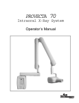
PROVECTA 70
Mobile Intraoral X-Ray System
Operator’s Manual
TABLE OF CONTENTS
Introduction . . . . . . . . . . . . . . . . . . . . . . . . . . . . . . . . . . . . . . . . . . . . . . . . . . . . . . . 4
Warranty . . . . . . . . . . . . . . . . . . . . . . . . . . . . . . . . . . . . . . . . . . . . . . . . . . . . . . . . . . 4
On-Line Warranty Registration . . . . . . . . . . . . . . . . . . . . . . . . . . . . . . . . . . . . . . . 4
Key Features . . . . . . . . . . . . . . . . . . . . . . . . . . . . . . . . . . . . . . . . . . . . . . . . . . . . . . 5
Safety Notice . . . . . . . . . . . . . . . . . . . . . . . . . . . . . . . . . . . . . . . . . . . . . . . . . . . . . .
General Safety Precautions . . . . . . . . . . . . . . . . . . . . . . . . . . . . . . . . . . . . . . . . . . .
Protection Against Radiation Warning . . . . . . . . . . . . . . . . . . . . . . . . . . . . . . . . . . .
Symbols Used . . . . . . . . . . . . . . . . . . . . . . . . . . . . . . . . . . . . . . . . . . . . . . . . . . . .
Knowledge of Warnings . . . . . . . . . . . . . . . . . . . . . . . . . . . . . . . . . . . . . . . . . . . . .
Warnings . . . . . . . . . . . . . . . . . . . . . . . . . . . . . . . . . . . . . . . . . . . . . . . . . . . . . . . .
Environmental Risk and Disposal . . . . . . . . . . . . . . . . . . . . . . . . . . . . . . . . . . . . . . .
5
6
6
6
7
7
7
Cleaning and Disinfecting . . . . . . . . . . . . . . . . . . . . . . . . . . . . . . . . . . . . . . . . . . . 8
Product Description . . . . . . . . . . . . . . . . . . . . . . . . . . . . . . . . . . . . . . . . . . . . . . . . . 8
Key Components . . . . . . . . . . . . . . . . . . . . . . . . . . . . . . . . . . . . . . . . . . . . . . . . . . 8
Provecta 70 Mobile System Parts Identification . . . . . . . . . . . . . . . . . . . . . . . . . . . . . 9
T e c h n i c a l S p e c i f i c a t i o n s . . . . . . . . . . . . . . . . . . . . . . . . . . . . . . . . . . . . . . . . . . . . . 10
Technical Features . . . . . . . . . . . . . . . . . . . . . . . . . . . . . . . . . . . . . . . . . . . . . . . . . 10
Tubehead Features . . . . . . . . . . . . . . . . . . . . . . . . . . . . . . . . . . . . . . . . . . . . . . 10-11
X-Ray Tube Features . . . . . . . . . . . . . . . . . . . . . . . . . . . . . . . . . . . . . . . . . . . . . . . 11
Environmental Conditions . . . . . . . . . . . . . . . . . . . . . . . . . . . . . . . . . . . . . . . . . . . . 11
Apparatus and Detachable Parts Weight . . . . . . . . . . . . . . . . . . . . . . . . . . . . . . . . . 11
Selected Exposure Time and Corrected Actual Exposure Time . . . . . . . . . . . . . . . . . . 11
Exposure Time Correction Factors vs Line Voltage . . . . . . . . . . . . . . . . . . . . . . . . . . . 12
Technical Factors Measuring Method . . . . . . . . . . . . . . . . . . . . . . . . . . . . . . . . . . . . 13
X-Ray Tube Curves . . . . . . . . . . . . . . . . . . . . . . . . . . . . . . . . . . . . . . . . . . . . . . . . . 13
X - R a y T u b e h e a d C o m p o n e n t s . . . . . . . . . . . . . . . . . . . . . . . . . . . . . . . . . . . . . . . . 14
X-Ray Tubehead Specifications . . . . . . . . . . . . . . . . . . . . . . . . . . . . . . . . . . . . . . .
Filament Characteristics . . . . . . . . . . . . . . . . . . . . . . . . . . . . . . . . . . . . . . . . . . . . .
Filament Loading . . . . . . . . . . . . . . . . . . . . . . . . . . . . . . . . . . . . . . . . . . . . . . . . . .
X-Ray Tubehead Cooling . . . . . . . . . . . . . . . . . . . . . . . . . . . . . . . . . . . . . . . . . . . . .
Cooling Curve of Tubehead . . . . . . . . . . . . . . . . . . . . . . . . . . . . . . . . . . . . . . . . . .
15
15
15
16
16
S y s t e m P o r t a b i l i t y . . . . . . . . . . . . . . . . . . . . . . . . . . . . . . . . . . . . . . . . . . . . . . . . . . 17
S y s t e m A c t i v a t i o n . . . . . . . . . . . . . . . . . . . . . . . . . . . . . . . . . . . . . . . . . . . . . . . . . . 18
X - R a y C o n t r o l P a n e l F u n c t i o n s . . . . . . . . . . . . . . . . . . . . . . . . . . . . . . . . . . . . . 18-19
Keypad Operation . . . . . . . . . . . . . . . . . . . . . . . . . . . . . . . . . . . . . . . . . . . . . . . . . .
Increase Select Button . . . . . . . . . . . . . . . . . . . . . . . . . . . . . . . . . . . . . . . . . . . . . .
Decrease Select Button . . . . . . . . . . . . . . . . . . . . . . . . . . . . . . . . . . . . . . . . . . . . . .
Tooth Select Mode Select Button . . . . . . . . . . . . . . . . . . . . . . . . . . . . . . . . . . . . . . .
Adult/Child Mode Select Button . . . . . . . . . . . . . . . . . . . . . . . . . . . . . . . . . . . . . . .
Digital/Film Mode Select Button . . . . . . . . . . . . . . . . . . . . . . . . . . . . . . . . . . . . . . .
Default Exposure Time Settings . . . . . . . . . . . . . . . . . . . . . . . . . . . . . . . . . . . . . . . .
2
20
20
20
20
21
21
21
TABLE OF CONTENTS
Keypad Operation: Custom Programming . . . . . . . . . . . . . . . . . . . . . . . . . . . . . .
Changing Default Settings to Customized Values . . . . . . . . . . . . . . . . . . . . . . . . . . .
Changing Display to Pulses . . . . . . . . . . . . . . . . . . . . . . . . . . . . . . . . . . . . . . . . . . .
Changing Display to Seconds . . . . . . . . . . . . . . . . . . . . . . . . . . . . . . . . . . . . . . . . .
Changing Default Tooth Settings . . . . . . . . . . . . . . . . . . . . . . . . . . . . . . . . . . . . . . .
Changing Default Child Multiplier Ratio . . . . . . . . . . . . . . . . . . . . . . . . . . . . . . . . . .
Changing Film Multiplier Ratio Settings . . . . . . . . . . . . . . . . . . . . . . . . . . . . . . . . . .
Changing Digital Multiplier Ratio Settings . . . . . . . . . . . . . . . . . . . . . . . . . . . . . . . .
Factory Reset . . . . . . . . . . . . . . . . . . . . . . . . . . . . . . . . . . . . . . . . . . . . . . . . . . . . .
22
22
22
22
23
23
24
24
24
System Operation . . . . . . . . . . . . . . . . . . . . . . . . . . . . . . . . . . . . . . . . . . . . . . . . . .
Setting the Exposure . . . . . . . . . . . . . . . . . . . . . . . . . . . . . . . . . . . . . . . . . . . . . . . .
Automatic Exposure Time Selection . . . . . . . . . . . . . . . . . . . . . . . . . . . . . . . . . . . . .
Manual Exposure Time Selection . . . . . . . . . . . . . . . . . . . . . . . . . . . . . . . . . . . . . . .
Exposure Emission Procedure . . . . . . . . . . . . . . . . . . . . . . . . . . . . . . . . . . . . . . . . .
Reading the Exposure Counter . . . . . . . . . . . . . . . . . . . . . . . . . . . . . . . . . . . . . . . .
25
25
25
26
27
27
S y s t e m R e a c h a n d S t o r a g e D i m e n s i o n s . . . . . . . . . . . . . . . . . . . . . . . . . . . . . . . . 28
R a d i o g r a p h i c T r o u b l e s h o o t i n g . . . . . . . . . . . . . . . . . . . . . . . . . . . . . . . . . . . . . . 29-30
S y s t e m M a i n t e n a n c e . . . . . . . . . . . . . . . . . . . . . . . . . . . . . . . . . . . . . . . . . . . . . . . . 31
S y s t e m E r r o r M e s s a g e s . . . . . . . . . . . . . . . . . . . . . . . . . . . . . . . . . . . . . . . . . . . . 31-34
N o t e s . . . . . . . . . . . . . . . . . . . . . . . . . . . . . . . . . . . . . . . . . . . . . . . . . . . . . . . . . . . . 35
3
INTRODUCTION
Congratulations, your new PROVECTA 70 Mobile Intraoral X-ray has been engineered and manufactured by Air Techniques to provide you with years of reliable service.
The PROVECTA 70 provides a mobile x-ray solution that creates radiographs of excellent quality. It
performs equally well using digital or film-based imaging media.
Review and follow the guidelines included in this manual to thoroughly become familiar with the
installation, maintenance, operating and safety procedures. This will ensure that your PROVECTA
70 gives you the highest level of service.
Your PROVECTA 70 Mobile Intraoral X-Ray model A2100 contains the following components:
ITEM
PART NUMBER
Scissor Arm
A2120
70kVp 8mA Tubehead
A2250
X-ray Control Panel
A2750
X-ray Arm Support Platform
A2615
Mounting Hardware
A2710
Users Manual
A2741
Service Manual
A2508
Warranty Card
N/A
Form FDA 2579
N/A
WARRANTY
The PROVECTA 70 Intraoral X-ray is warranted to be free from defects in material and workmanship
from the date of installation for a period of twenty-four (24) months.
Any item returned to our factory in Hicksville, New York through an Air Techniques’ Authorized Dealer,
will be repaired or replaced at our option at no charge provided that our inspection shall indicate it to
have been defective. Dealer labor, shipping and handling charges are not covered by this warranty.
This warranty does not apply to damage due to shipping, misuse, careless handling or repairs by other
than authorized service personnel. Warranty void if installed or serviced by other than Authorized Air
Techniques’ Dealer service personnel. Air Techniques, Inc. is not liable for indirect or consequential
damages or loss of any nature in connection with this equipment.
This warranty is in lieu of all other warranties express or implied. No representative or person is authorized to assume for us any liability in connection with the sale of our equipment.
ON-LINE WARRANTY REGISTRATION
Quickly and easily register your new Provector 70 on-line. Just have your product model number and
serial number available and log onto www.airtechniques.com. When at the Air Techniques website, select the Warranty Registration link and complete the registration form. This on-line registration
ensures a record for the warranty period and helps Air Techniques keep you informed of product
updates and other valuable information.
4
KEY FEATURES
1.
Microprocessor controlled.
2.
Exposure compensation over input AC voltage range.
3.
User selectable exposure time in seconds/pulses.
4.
20 preset exposure times.
5.
Manually selectable exposure times.
6.
Programmable Adult/Child ratio.
7.
Programmable Film setting.
8.
Programmable Digital setting.
9.
Two memorized exposure settings.
10.
Stable positioning.
11.
X-ray Control Panel.
12.
Handheld Exposure Switch.
13.
Designed for ease of use.
14.
Built in tubehead simulator for training and testing the X-Ray Control operation.
SAFETY NOTICE
ATTENTION USERS:
MANUFACTURING DATE CODE ON SERIAL NUMBER LABEL IS IN THE FORMAT: Month YYYY.
Warns users that uninsulated voltage
within the unit may be of sufficient
magnitude to cause electric shock.
Indicates type BF equipment in
accordance with IEC 601-1
A S S IF I
ED
CL
Alerts users to important Operating
and Maintenance instructions. Read
carefully to avoid any problems.
MEDICAL ELECTRICAL EQUIPMENT
WITH RESPECT TO ELECTRICAL SHOCK, FIRE, MECHANICAL AND OTHER SPECIFIED HAZARDS ONLY
IN ACCORDANCE WITH UL-60601-1, CAN/CSA C22.2 NO.601.1
66CA
DO NOT ATTEMPT INTERNAL SERVICE
The interior of the Main Assembly is only accessible by removing hardware with tools and should only be
opened and serviced by an authorized Air Techniques’ Dealer Service representative. Call your authorized
Air Techniques’ dealer for service. Since the interior of the unit contains high voltage components, failure to
heed this warning may result in equipment damage, personal injury and/or death.
5
SAFETY NOTICE
GENERAL SAFETY PRECAUTIONS
This equipment has been designed and manufactured in compliance with applicable safety
requirements; moreover, this manual provides all the necessary information for correct and safe
utilization. It provides warnings related to risks associated with the PROVECTA 70 and should
be read very carefully. Air Techniques Inc. shall not be responsible for:
any use of PROVECTA 70 equipment different from that for which it was been
designed,
any damage to the equipment, the operator or the patient caused either by incorrect
installation or maintenance not compliant with the procedures contained in the
relevant user’s and installation manuals provided with the equipment, or by
incorrect operation techniques,
any mechanical and/or electrical changes made during or after installation, different
from those specified in the service manual.
Only qualified service personnel, authorized by Air Techniques, Inc., or its dealers are
allowed to perform repairs on the equipment.
PROTECTION AGAINST RADIATION WARNING:
Radiation protection is generally prescribed or regulated by local, State or Federal regulatory
agencies. These regulations are beyond the scope of this manual. Operation and use of the device
should be limited to trained personnel in accordance with local, state and federal regulations.
a. The film, phosphor plate or sensor must be introduced in the patient’s mouth either
manually or by means of appropriate holders; it must never be held by the operator, and
only the patient may hold it if required.
b. During radiation exposure, the operator must not be in contact with the tubehead or the
collimator.
c. During radiation exposure, the operator must keep at a certain distance from the X-ray
source (at least 6-1/2 feet), in a direction opposite to that of X-ray emission.
d. During radiation exposure, no one other than the operator and the patient must be
present in the room.
e. To reduce the unwanted effects of secondary radiation on the patient, we suggest using
the relevant leaded protection aprons.
SYMBOLS USED
The following symbols are used on the PROVECTA 70 and in this manual.
AC
Connection to Neutral Conductor
Connection to Line Conductor
Protection Grounding
Functional Grounding
OFF; Equipment not Connected to Power Line
ON; Equipment Connected to Power Line
X-ray Emission
6
SAFETY NOTICE
KNOWLEDGE OF WARNINGS
Users must exercise every precaution to ensure personnel safety, and be familiar with the
warnings presented throughout this manual and summarized below.
WARNINGS:
Federal law restricts this device to sale by or on the order of a dentist.
This equipment complies with DHHS performance standard 2l CFR Subchapter J.
This equipment complies with the requirements of IEC 60601-2-7, and UL 60601-1.
The X-ray Tubehead Assembly P/N A2250 complies with IEC 60601-2-28 (1993).
The equipment must be used in compliance with the procedures contained in this manual
and shall not be used for purposes different from those described in this manual.
To protect the patient from X-ray radiation, protection accessories such as standard leaded
aprons, must be used.
PROVECTA 70 is classified as dental imaging equipment and must therefore be used only
under the supervision of qualified dental staff, having the necessary knowledge in the field
of radiation.
The user bears legal responsibility related to the possession, installation and use of this
device. Do not remove panels. Removing panels would create an electric shock hazard.
Equipment is not suitable for use in the presence of flammable anesthetic mixture with air or
with oxygen or nitrous oxide.
For continued protection against risk of fire, replace only with the same type and rating of
circuit breakers and fuses.
Replace components only with authorized replacement parts identified in this manual.
Before performing any maintenance, the equipment must be unplugged from the electrical
wall outlet.
Do not allow water or other liquids to penetrate inside the equipment to avoid short circuits
and corrosion.
Although the x-ray doses provided by modern equipment are reduced as low as reasonably
possible, during exposure the operator must take all the necessary precautions and/or
protection measures for the patient and themselves, in compliance with existing regulations.
PROVECTA 70 must be switched off during the use of High Frequency surgical devices or
similar instruments placed near the equipment.
Do Not place ANY additional weight on the scissor arms.
Note:
Air Techniques, Inc., is not responsible for disposal of the apparatus or parts thereof
and for the related expenses.
ENVIRONMENTAL RISK AND DISPOSAL
The equipment contains - in some of its parts - solid and liquid substances which must be disposed
of at appropriate recycling centers conforming to all local, state and federal regulations.
In particular, the equipment contains the following materials and/or components:
Tubehead: non-biodegradable plastic materials, metals, glass, dielectric oil, lead, tungsten.
Other parts of the equipment: non-biodegradable plastics, metals, printed circuits, and
electronic components.
7
CLEANING AND DISINFECTING
CLEANING AND DISINFECTING PROCEDURES
In order to ensure proper hygiene and cleaning of the equipment, the following procedures must be
followed thoroughly:
Warning:
Disconnect the branch circuit breaker or unplug from the electrical
outlet before performing cleaning procedures. Active internal circuits
remain connected to main voltage even when main power switch is
turned off.
Exterior Surfaces: Wipe the outside surfaces with a paper towel dampened with a disinfectant solution
or household, non-abrasive cleaner. DO NOT SPRAY SOLVENTS OR LIQUID DIRECTLY ON THE XRAY UNIT. BE CAREFUL NOT TO ALLOW SOLVENTS TO RUN OR DRIP into the PROVECTA 70. This
could cause damage to the PROVECTA 70. Allow to air dry before plugging in or turning back on.
Parts in Contact with the Patient’s Skin: To ensure proper cleaning of these parts, periodic disinfection
with an approved EPA Non Corrosive Surface Disinfectant such as Birex® se is recommended.
PRODUCT DESCRIPTION
KEY COMPONENTS
PROVECTA 70 Mobile intraoral X-ray equipment is comprised of the following components:
a. Scissor Arm - The scissor arm consists of inboard and outboard arms joined by a
double joint. This allows linear and upward extension enabling the tubehead to
remain balanced in all positions.
b. Tubehead with Beam Limiting Device - 70 kVp voltage and 8 mA current
reduce exposure times and the amount of radiation absorbed by the patient. The
tubehead is equipped with a beam limiting device providing a 20 cm (8 inches)
source to skin distance and a 6 cm (2 3/8 inches) beam diameter at the output.
Mechanically, the tubehead is connected to the arm by means of a rotating contact,
allowing 360-degree horizontal rotation and 285-degree vertical rotation.
c. X-Ray Control Panel - The X-ray Control Panel is a microprocessor-controlled digital
timer that permits both manual selection and 5 automatic selections of exposure times.
An automatic selection function further allows the operator to choose among 20 pre-set
times according to the type of patient (adult or child), the type of tooth and digital or
film type. Additionally, 44 fixed times can be selected manually and ranges between
0.02 and 3.20 seconds. The integral timer automatically compensates for input line
voltage variations within a range of 120 V ± 10%.
d. Mobile X-Ray Support Platform - Mobile X-Ray Support Platform provides a
stable portable operating base for the PROVECTA 70.
e. Handheld Exposure Switch - The Handheld Exposure Switch is connected to the
X-ray Control Panel via a 18-inch coiled cable, which allows the operator to start an
x-ray exposure cycle while assuring exact tubehead positioning.
f. Power Line Cord - This 16-foot cable connects between an AC wall outlet and the
Mobile X-Ray Support Platform to provide connection of the operating 120 AC line
voltage.
8
PRODUCT DESCRIPTION
Provecta 70 Mobile System Parts Identification
Scissor Arm
Outboard Scissor
Arm Section
Inboard Scissor
Arm Section
Yoke
X-Ray Control
Panel
Tubehead
with Beam
Limiting
Device
Handheld Exposure
Switch
Mobile X-Ray
Support Platform
Power
Cord
Locking Casters
9
TECHNICAL SPECIFICATIONS
Technical Features
Equipment Manufacturer
IEC 60601-1 Classification
Degree of protection against ingress of water
Air Techniques Inc.
Class I with type B applied parts
Ordinary
Note: Equipment is not suitable for use in the presence of flammable anesthetic mixture with air or
with oxygen or nitrous oxide.
Mode of operation
Continuous operation with intermittent loading
FDA 21 CFR Classification
Line voltage
Line frequency
Rated current
Power consumption
Line Voltage Regulation
Apparent Resistance of Supply Mains
Circuit Breakers
Circuit Board Fuses
Class II
120V +/- 10%
60Hz
8.2 Amps
0.8 kVA @ 120V
<3%
0.43 ohms
10 Amp
10A 250V Ceramic Fast Acting (0.25 x 1.25 IN)
and 630mA 250V Fast Acting (5 mm x 20 mm)
from 0.02 to 3.20 seconds in 44 steps
20 pre-set times
Microprocessor controlled exposure times, with
automatic compensation for line voltage variations.
Preset exposure times
Anatomic selection
Exposure control
Timer Accuracy on the selected Exposure Time
(This is the value of the operator selected timer
setting).
+/- 5% or +/- 33ms (whichever is greater).
Timer Accuracy on the Corrected Exposure Time
(This is the actual time of exposure, indicated
on the Control Panel during emission and determined
by the internal algorithm as a function of the line
voltage).
The range of adjustment is 73% to 149% as the AC
line voltage changes within the rated voltage range.
See note on next page.
+/- 5% or +/- 33ms (whichever is greater).
Mobile X-ray dimensions
79½ ” H x 28” W x 31” D
Tubehead Features
Rated output voltage
High voltage circuit type
Tubehead current
Tubehead Power
Total filtration
Transformer insulation
Cooling
Pre-heating time
Interval between exposure / duty cycle
Beam Limiting Device
Tubehead Assembly dimensions (less yoke)
70 kVp +/- 15% over 108-132 V
108-132 VAC Single phase, self-rectifying
8 mA +/- 2 mA
0.8 kw
2mm Aluminum equivalent @70 kVp
Oil bath
Convection
100ms
32 times X-ray time / 1: 32
Incorporated in Tubehead Assembly (non-removable)
5” H x 7.5” W x 15” D
10
TECHNICAL SPECIFICATIONS
Tubehead Features (continued)
Minimum source to skin distance
Maximum symmetrical radiation field @ 20 cm
(X-ray beam diameter)
Radiation leakage at 1 m
Technical factors for radiation leakage
2 3/8” (6 cm)
<50 mR/h, duty cycle 1: 32
70 kVp, 8mA, 3 seconds
X-ray Tube Features
Manufacturer
Type
Focal spot
Inherent filtration
Anode thermal capacity
CEI- Bologna- Italy
OCX/70-G
0.8 mm (IEC 336)
0.5 mm Al equivalent
6kJ
20 cm (8”)
Environmental Conditions
Operating temperature range
Operating relative humidity range
Temperature range for transport and storage
Max. relative humidity for transport and storage
Min. atmospheric pressure for storage and
transport
+50°F - +104°F (+10°C - +40°C)
30% - 75%
-4°F . +158°F (-20°C • +70°C)
<95 % non condensing
0.6 atmospheres
Apparatus and Detachable Parts Weight
Gross weight including packaging
Net apparatus weight in standard configuration
Scissors arm
Tubehead
Mobile Platform with Controller
170 lbs.
155 lbs. (including scissors arm)
24 lbs.
18.5 lbs.
112.5 lbs.
Selected Exposure Time and Corrected Actual Exposure Time
The Air Techniques' X-ray Control Panel incorporates a special Timer feature that automatically corrects the
selected exposure time when the line voltage varies from 120 V. A change in the AC line voltage affects the
peak voltage applied to the X-Ray tube and the value of high voltage significantly affects the spectrum of the
radiation that ultimately affects the optical density of the imaging media. The purpose of the X-ray Control timer
correction is to obtain the same nominal optical density on the imaging media independent of the AC line voltage variations from 108-132 Volts.
The automatic correction of the exposure time works as follows:
The internal voltage measuring circuit in the X-ray Control Timer continuously monitors the AC line voltage.
When the user selects the desired exposure time and presses the X-ray Exposure button, the exposure time will
be automatically adjusted based upon the measured AC line voltage. The corrected actual exposure time will be
displayed until the X-ray Exposure button is released.
Note:
Electromagnetic interference between the equipment and other devices can
occur. Do not use the equipment in close conjunction with sensitive devices, or
devices creating high electromagnetic disturbances.
11
TECHNICAL SPECIFICATIONS
The corrected exposure is calculated applying a correction factor to the selected exposure time, based
on an empirical law that correlates the dose with the high voltage peak and consequently with the line
voltage. The qualitative relationship between the multiplying factor and the line voltage is shown in the
following picture:
12
TECHNICAL SPECIFICATIONS
TECHNICAL FACTORS MEASURING METHOD
kVp
The kVp is defined as the average of the peak high voltage after pre-heating
time and settling. The kVp is assessed with a non-invasive instrument having a
± 1% accuracy at the nominal AC input line voltage.
mA
The output current is defined as the average value of the current after pre-heating
time and settling. The output current can be measured by attaching a DC voltmeter
(0-10 VDC) to the connections behind the circular cap on the side of the Tubehead
yoke. The correlating relationship is 1 volt per mA of tube current.
t
The exposure time is defined as the time measured with a non-invasive meter.
Accuracy is verified by using an Innovision 8000 mAx instrument.
X-RAY TUBE CURVES
OCX / 70-G
Emission characteristics
13
X-RAY TUBEHEAD KEY COMPONENTS
X-ray Tubehead
Assembly
X-ray Beam Axis
Guide
Focal Point
Guide
Yoke
Angular Alignment
Gauge
14
X-RAY TUBEHEAD SPECIFICATIONS
Filament Characteristics
Loading
15
X-RAY TUBEHEAD SPECIFICATIONS
Cooling
Cooling curve of Tubehead
16
SYSTEM PORTABILITY
Note:
Power must be supplied from a dedicated branch circuit rated 15 AMP, 60Hz, 120 Volt.
No other equipment may be connected to the branch circuit.
The PROVECTA 70 is designed to be easily transported among patient operatories as needed. Transport the PROVECTA 70 by performing the following procedure:
1. Uplug the power line cord from AC wall outlet.
2. Hang power line cord on hook of support platform post.
3. Lower and lock tubehead to support platform post.
4. If necessary. return Handheld Exposure Switch to holder on X-ray Control Panel.
5. Unlock 2 wheel casters.
6. Using hand grips on support platform post, transport the PROVECTA 70 to next location.
7. Locate the PROVECTA 70 in desired area and lock the 2 wheel casters.
8. Plug power line cord into AC wall outlet.
Arm Lock
X-Ray Control
Panel
Tubehead
Handheld Exposure
Switch
Line Cord
Hook
Power Line Cord
Locking
Casters
17
SYSTEM ACTIVATION
PROVECTA 70 TURN-ON PROCEDURE:
Turn on the PROVECTA 70 by performing the following procedure:
1. Place the Main Power Switch located on the bottom
of the X-Ray Control Panel in the ON ( I ) position.
2. Observe that the system self check function initiates
and the digital display displays following sequence :
a. AtI
b. Display Test 8.8.8.
c. Firmware Version (e.g. A)
d. Last setting e.g. (e.g. 0.63)
Note:
X-Ray Control
Panel
See System Error Messages,pages 31 through 34, for a
listing and description of possible start-up error codes.
3. Once the self check function completes successfully, the
system starts in the Upper Molar, Adult & Film Processor
modes and is ready for operation. Verify associated
indicator illumination and exposure time display.
Note:
When power is turned off, the system retains the last
selected manual and preset modes. Upon turn on, the
system resumes operation as set prior to turning off.
Tubehead
Main Power Switch
X-RAY CONTROL PANEL FUNCTIONS
DIGITAL DISPLAY
PULSE TIME EXPOSURE MODE
Indicator Lamp
INCREASE Select Button
SECONDS TIME EXPOSURE
MODE Indicator Lamp
DECREASE Select Button
TOOTH SELECT
Mode Select Button
UPPER MOLAR Indicator Lamp
LOWER INCISOR Indicator Lamp
UPPER PRE-MOLAR, UPPER
CANINE, LOWER MOLAR
Indicator Lamp
LOWER PRE-MOLAR
Indicator Lamp
BITE-WING & UPPER
INCISOR Indicator Lamp
ADULT MODE Indicator Lamp
ADULT/CHILD
Mode Select Button
CHILD MODE Indicator Lamp
DIGITAL Processing
Indicator Lamp
FILM Processing
Indicator Lamp
ACTIVE X-RAY EMISSION
CAUTION Indicator Lamp
DIGITAL/FILM
Mode Select Button
Note:
All automatic settings are confirmed by the corresponding LED illumination.
18
X-RAY CONTROL PANEL FUNCTIONS
X-Ray Control Panel - All functional operating control of the PROVECTA 70 X-Ray is provided by
the X-ray Control Panel. It allows both automatic and manual selections of exposure times. The 5
automatic selection functions allow the operator to further choose among 20 pre-set times according
to the patient type (adult or child), tooth type and media type (digital or film). An audible signal
sounds during any X-ray emission. In addition, this signal is heard to confirm keypad button selection
and when certain errors occur. The location of the panel controls and indicators are shown in the
preceding illustration, while the function of each is summarized below and described on the following
pages.
DIGITAL DISPLAY Panel
8.88
A 3-character digital display that shows the selected time value (pulses
or seconds) during operational phases as follows:
1. Exposure Preparation Phase - displays the selected exposure
time in both automatic or manual modes.
2. Exposure Phase - displays the corrected exposure time adjusted
to compensate for variations in the input AC line voltage.
3. Cooling Phase - displays remaining tubehead cooling time.
INCREASE Select Button
A membrane keypad switch that disables all automatic settings and
allows the user to manually increase exposure time as necessary.
DECREASE Select Button
A membrane keypad switch that disables all automatic settings and
allows the user to manually decrease exposure time as necessary.
PULSE TIME EXPOSURE MODE
Indicator Lamp
A LED indicator lamp that illuminates green to confirm selection of the
PULSE time mode for Digital Display operation.
SECONDS TIME EXPOSURE MODE
Indicator Lamp
A LED indicator lamp that illuminates green to confirm selection of the
SECONDS time mode for Digital Display operation.
TOOTH SELECT Mode Select Button
A membrane keypad switch that allows sequential mode selection of
preset exposure time among five different teeth categories as follows:
UPPER MOLAR Indicator Lamp
A LED indicator lamp that illuminates green to confirm selection of
preset exposure time for the UPPER MOLAR tooth category.
UPPER PRE-MOLAR, UPPER
CANINE, LOWER MOLAR
Indicator Lamp
A LED indicator lamp that illuminates green to confirm selection of
preset exposure time for the UPPER PRE-MOLAR, UPPER
CANINE, LOWER MOLAR tooth category.
BITE-WING & UPPER INCISOR
Indicator Lamp
A LED indicator lamp that illuminates green to confirm selection of
preset exposure time for the BITE-WING & UPPER INCISOR tooth
category.
LOWER PRE-MOLAR Indicator Lamp
A LED indicator lamp that illuminates green to confirm selection of
preset exposure time for the LOWER PRE-MOLAR tooth category.
LOWER INCISOR Indicator Lamp
A LED indicator lamp that illuminates green to confirm selection of
preset exposure time for the LOWER INCISOR tooth category.
ADULT/CHILD Mode Select Button
A membrane keypad switch that toggles between selection of preset
exposure time for ADULT and CHILD exposure modes as follows:
ADULT MODE Indicator Lamp
A LED indicator lamp that illuminates green to confirm selection of
preset exposure time for the ADULT exposure mode.
CHILD MODE Indicator Lamp
A LED indicator lamp that illuminates green to confirm selection of
preset exposure time for the CHILD exposure mode.
DIGITAL/FILM Mode Select Button
A membrane keypad switch that toggles between selection of preset
exposure time for DIGITAL and FILM exposure modes as follows:.
DIGITAL Processing Indicator Lamp
A LED indicator lamp that illuminates green to confirm selection of
preset exposure time for the DIGITAL processing mode.
FILM Processing Indicator Lamp
A LED indicator lamp that illuminates green to confirm selection of
preset exposure time for the FILM processing mode (D-speed film).
ACTIVE X-RAY EMISSION CAUTION
Indicator Lamp
A LED indicator lamp that illuminates yellow to alert the user that x-ray
radiation is present during PROVECTA 70 current operation.
19
KEYPAD OPERATION
INCREASE SELECT BUTTON
DECREASE SELECT BUTTON
The INCREASE and DECREASE Select Buttons are membrane keypad switches that allow the user to
disable the automatic operating mode default time settings (Adult/Child, Patient Size, Tooth Selection)
and manually increase or decrease exposure time as necessary to any of the 44 values shown below in
seconds or pulses.
When a manual exposure time setting is desired, press the associated button (Increase or Decrease)
once to display the last manually set exposure time. Manually change the time setting in one increment
or decrement by releasing the button and then pressing once. Rapid advancement through the 44 time
values is accomplished by keeping the button depressed. Release button to set desired exposure time.
Return to the last automatic mode default time settings by pressing any Mode Selection Button
(Film/Digital, Adult/Child, Tooth Select).
TIME VALUES IN SECONDS
0.02
0.04
0.05
0.06
0.08
0.10
0.12
0.14
0.15
0.16
0.18
0.20
0.22
0.23
0.25
0.27
0.28
0.30
0.32
0.33
0.35
0.36
0.38
0.40
0.42
0.43
0.45
0.47
0.50
0.55
0.60
0.63
0.70
0.80
0.90
1.00
1.25
1.30
1.40
1.60
2.00
2.50
3.00
3.20
TIME VALUES IN PULSES
1
2
3
4
5
6
7
8
9
10
11
12
13
14
15
16
17
18
19
20
21
22
23
24
25
26
27
28
30
33
36
38
42
48
54
60
75
78
84
96
120
150
180
192
TOOTH SELECT MODE SELECT BUTTON
A membrane keypad switch located in the center of the tooth symbols allows sequential mode
selection of preset default exposure times for each of the five indicated teeth types. Each time the
TOOTH/SELECT Mode Select Button, shown below, is pressed, the associated LED lamp illuminates
and an audible signal sounds to indicate selection. Default Preset exposure times are based on
D-speed film.
The five selectable default preset exposure
times correlating to teeth categories are as
follows:
UPPER MOLAR
0.63 seconds
UPPER PRE-MOLAR,
UPPER CANINE,
LOWER MOLAR
0.50 seconds
BITE-WING &
UPPER INCISOR
0.32 seconds
LOWER PRE-MOLAR
0.40 seconds
LOWER INCISOR
TOOTH SELECT
Mode Select Button
UPPER MOLAR LED
Factory setting 0.63 sec.
UPPER PRE-MOLAR
UPPER CANINE
LOWER MOLAR LED
Factory setting 0.50 sec.
LOWER INCISOR LED
Factory setting 0.30 sec.
BITE-WING & UPPER
INCISOR LED
Factory setting 0.32 sec.
LOWER PRE-MOLAR LED
Factory setting 0.40 sec.
0.30 seconds
20
KEYPAD OPERATION
ADULT/CHILD MODE SELECT BUTTON
A membrane keypad switch that toggles between
selection of preset exposure time for ADULT and
CHILD exposure modes. By depressing the button
located between the symbols, the selection between
Adult and Child modes are made with the resulting
change in exposure time. Each time the ADULT/CHILD
Mode Select Button is pressed, the associated LED
lamp illuminates and an audible signal sounds to
indicate selection.
ADULT factory setting
is 1.00 or 100%
DIGITAL/FILM MODE SELECT BUTTON
A membrane keypad switch that toggles between automatic
exposure settings for specific media types commonly used with
the PROVECTA 70. The user can select between D-speed film
and digital radiology processing. When the FILM mode is
selected the system is set to process film at 100% exposure
time of D-speed film. When set in the DIGITAL mode, the
exposure time is reduced to values suitable for the use of
digital phosphor plate scanners such as A/T ScanX or sensors.
The factory setting for the
CHILD reduction is 0.5 (50%).
Digital X-Ray
factory-set reduction
is 0.50 or 50%.
Film factory setting
1.00 or 100% for
D-speed film.
An audible signal is sounded each time the DIGITAL/FILM
Mode Select Button is depressed and the associated LED is
illuminated to indicate selection.
DEFAULT EXPOSURE TIME SETTINGS
The following table lists the factory-set default setting combinations available by the operation of the
TOOTH SELECT, ADULT/CHILD and FILM/DIGITAL Mode Select Buttons.
PROVECTA 70 Available Preset Exposure Time Setting Combinations
21
KEYPAD OPERATION: CUSTOM PROGRAMMING
Note:
When power is turned off, the system retains the last selected manual and preset modes. Upon turn
on, the system resumes operation as set prior to turning off.
CHANGING DEFAULT SETTINGS TO CUSTOMIZE VALUES
The PROVECTA 70 factory default settings are based on D-speed film exposure with the digital display
set to show time values in seconds. These defaults allow automatic operation of the system by the
selection of the TOOTH SELECT, ADULT/CHILD and FILM/DIGITAL Mode Select Buttons. Although this
automatic operation is adequate for most applications, the PROVECTA 70 may be customized to meet
the needs of a specific application or individual preference.
Customize one or all of the six default settings listed below as necessary by performing the procedures
provided by the following paragraphs. When all changes have been accomplished, resume operation
of the PROVECTA 70 per System Operation instructions provided on page 25.
1. Changing Display to Pulses
2. Changing Display to Seconds
3. Changing Default Tooth Setting
4. Changing Default Child Multiplier Ratio
5. Changing Film Multiplier Ratio Settings
6. Changing Digital Multiplier Ratio Settings
CHANGING DISPLAY TO PULSES
The PROVECTA 70 is set at the factory to display exposure times in seconds. Perform the following
procedure to change the Digital Display panel to show time values in pulses:
1.
Turn the Power Switch OFF (0) and then to ON ( I ) again.
2.
When AtI is shown in the Digital Display panel, press and hold the INCREASE () Select
Button until PUL (pulses) appears in the display window. Verify that the PULSES indicator
illuminates on the control panel.
3.
Release the INCREASE () Select Button.
CHANGING DISPLAY TO SECONDS
When the PROVECTA 70 was changed to display in pulses and there is a need to change the time
value back to seconds, perform the following procedure:
1.
Turn the Power Switch OFF (0) and then to ON ( I ) again.
2.
When AtI is shown on the Digital Display panel, press and hold the INCREASE () Select
Button until SEC (seconds) appears in the display window. Verify that the SECONDS indicator
illuminates on the control panel.
3.
Release the INCREASE () Select Button.
22
KEYPAD OPERATION: CUSTOM PROGRAMMING
CHANGING DEFAULT TOOTH SETTINGS
The PROVECTA 70 provides 5 tooth settings and is factory set to start operation in the UPPER MOLAR.
Perform the following procedure to change one or all of the default tooth settings:
1.
Turn the Power Switch OFF (0) and then to ON ( I ) again.
2.
When the software version is displayed, A.. will appear along with the software version.
3.
Press the tooth select button to enter the default tooth setting programming mode.
4.
When SEL is shown on the Digital Display panel, press the INCREASE () Select Button.
One of the five tooth select indicator lamps will flash and the Digital Display panel will show
the current programmed default exposure setting for the selected tooth.
Within ten seconds, repeatedly press the INCREASE () Select Button until the desired tooth
category is selected.
5.
6.
Press the
TOOTH SELECT Mode Select Button to confirm selection.
7.
The Digital Display panel will flash together with the indicator lamp of the selected tooth to
indicate the default setting can be changed.
8.
Within ten seconds, press the INCREASE () or DECREASE () Select Button to the desired
default setting.
9.
Within ten seconds, press the
default tooth setting program.
TOOTH SELECT Mode Select Button to exit the
10. Repeat steps 1- 9 until all desired changes have been made.
CHANGING DEFAULT CHILD MULTIPLIER RATIO
The PROVECTA 70 default Child setting is 50% of the adult setting. Perform the following procedure to
change the default child mode multiplier ratio setting:
1.
Turn the Power Switch OFF (0) and ON ( I ) again.
2.
When the software version is displayed A.. press the
ADULT/CHILD Mode Select
Button to enter the CHILD multiplier ratio programming mode.
3.
When CHI is shown on the Digital Display panel, press the
Mode Select Button to confirm selection.
4.
Verify that the Digital Display panel shows the factory setting of 0.50.
5.
Within 10 seconds press the INCREASE () or DECREASE () Select Button to set the
desired multiplier ratio with respect to D-speed film.
6.
Within 10 seconds press the
TOOTH SELECT
TOOTH SELECT Mode Select Button to select.
23
KEYPAD OPERATION: CUSTOM PROGRAMMING
Note:
If using film other than D-Speed film, change the film multiplier ratio as recommended by
the film manufacturer prior to use.
CHANGING FILM MULTIPLIER RATIO SETTING
The PROVECTA 70 default FILM setting is 100% of D-speed film exposure time. Perform the following
procedure to change the default film multiplier ratio setting:
1. Turn the Power Switch OFF (0) and ON ( I ) again.
2. When the software version is displayed A.. press the
DIGITAL/FILM Mode Select
Button to enter the DIGITAL/FILM multiplier ratio programming mode.
3. When FIL is shown on the Digital Display panel, press the
TOOTH SELECT Mode
Select Button to confirm selection.
4. Verify that the Digital Display panel shows the factory setting of 1.00 (100% of D-speed film
exposure time).
5. Within 10 seconds press the INCREASE () or DECREASE () Select Button to set the
desired multiplier ration with respect to D-speed film exposure time.
6. Within 10 seconds press the
TOOTH SELECT Mode Select Button to select.
CHANGING DIGITAL MULTIPLIER RATIO SETTING
The PROVECTA 70 default DIGITAL setting is 50% of the FILM setting (D-speed film exposure time).
Perform the following procedure to change the default digital media multiplier ratio settings:
1.
Turn the Power Switch OFF (0) and ON ( I ) again.
2.
When the software version is displayed A.. press the
the DIGITAL/FILM multiplier ratio programming mode.
3.
When FIL is shown on the Digital Display panel, press the INCREASE () Select Button.
4.
Verify that the Digital Display panel shows DIG.
5.
Press the
6.
Verify that the Digital Display panel shows the factory setting of 0.50.
7.
Within 10 seconds press the INCREASE () or DECREASE () Select Button to set the
desired multiplier ratio with respect to D-speed film exposure time.
8.
Within 10 seconds press the
DIGITAL/FILM button to enter
TOOTH SELECT Mode Select Button to confirm selection.
TOOTH SELECT Mode Select Button to select.
FACTORY RESET
Performing factory reset returns all operating values and settings of the PROVECTA 70 to the values set
at the factory during manufacture. Refer to the PROVECTA 70 Available Preset Exposure Time Setting
Combinations table on page 25 for a listing of the factory-set default exposure settings. Make sure to
write down all manually customized settings prior to performing the factory reset sequence. Any settings
changed during operation will be lost upon completion of reset. Reset all operating values and settings
by performing the following procedure.
1. Turn the Power Switch OFF (0) and then to ON ( I ) again.
2. When the initials AtI appear in the Digital Display panel, press and hold the DECREASE ()
Select Button until FAC (Factory Reset) appears in the display.
3. Verify that the display shows 0.63 seconds and the SECONDS, UPPER MOLAR, ADULT, AND
FILM LED indicator lamps are illuminated. The PROVECTA 70 is now reset to operate with the
factory-set default settings.
24
SYSTEM OPERATION
SETTING THE EXPOSURE
The PROVECTA 70 is normally operated in the automatic operation mode where the selection
combinations of the TOOTH SELECT, ADULT/CHILD and FILM/DIGITAL Mode Select Buttons provide
20 separate default exposure settings for specific exposure applications. These preset exposure time
values (seconds or pulses) associated with the mode select button setting combinations are displayed
as shown in the table below. The suggested exposure times are based on D-speed film exposure.
Note:
Keypad button selection is confirmed by the sounding of an audible signal and illumination
of the corresponding indicator lamp .
Automatic Exposure Time Selection - Perform the following procedure to set the PROVECTA 70
to operate in the automatic mode using preset exposure time values.
1
Press any Mode Selection Button
(Tooth Select, Film/Digital,
Adult/Child) to initiate the automatic exposure mode of operation.
2.
Press the
ADULT/CHILD Mode Select Button to select the patient size parameter.
Verify that the corresponding
Adult Mode or
Child Mode indicator lamp illuminates
and audible signal sounds for the desired preset exposure setting selection.
3.
Press the
DIGITAL/FILM Mode Select Button to select the type of media processing.
Verify that the corresponding indicator lamp
Digital Mode or
Film Mode illuminates
and audible signal sounds for the desired preset exposure setting selection.
4.
Press the
TOOTH SELECT Mode Select Button to sequentially advance through the
5 tooth categories until the corresponding indicator lamp illuminates for the desired tooth
type selection. The resultant exposure setting is shown on the Digital Display in seconds or
pulses as required.
PROVECTA 70 Available Preset Exposure Time Setting Combinations
25
SYSTEM OPERATION
Note:
If using other than D-Speed film, change the film multiplier ratio as recommended by the
film manufacturer prior to use (refer to the section on Custom Programming on page 22).
The PROVECTA 70 also allows the user to manually set exposure settings to meet the needs of specific
patient applications or individual user preference. Using the INCREASE () or DECREASE () Select
Buttons, the manual exposure selection mode enables the user to set exposure time values (seconds or
pulses) as required. These user-set exposure time values offer 44 specific value settings shown in the
tables below.
Manual Exposure Time Selection- Perform the following procedure to set the PROVECTA 70 to
operate in the manual exposure selection mode using user-set exposure time values.
1.
Press either the INCREASE () or DECREASE () Select Buttons to initiate the manual
exposure selection mode of operation. The Digital Display panel shows the last manually
set exposure time.
Note:
2.
3.
When set in the manual exposure selection mode, exposure time is increased by pressing
the INCREASE () Select Button and decreased by pressing the DECREASE () Select
Button. The resultant exposure setting is shown on the Digital Display panel in seconds or
pulses.
Press either the INCREASE () or DECREASE () Select Buttons once to manually
.change the time setting in one increment or decrement. Rapid advancement through the
entire range of 44 time values is accomplished by keeping the button depressed.
Release button to set desired exposure time.
Verify that the desired exposure time value is shown on the Digital Display panel.
TIME VALUES IN SECONDS
0.02
0.04
0.05
0.06
0.08
0.10
0.12
0.14
0.15
0.16
0.18
0.20
0.22
0.23
0.25
0.27
0.28
0.30
0.32
0.33
0.35
0.36
0.38
0.40
0.42
0.43
0.45
0.47
0.50
0.55
0.60
0.63
0.70
0.80
0.90
1.00
1.25
1.30
1.40
1.60
2.00
2.50
3.00
3.20
TIME VALUES IN PULSES
1
2
3
4
5
6
7
8
9
10
11
12
13
14
15
16
17
18
19
20
21
22
23
24
25
26
27
28
30
33
36
38
42
48
54
60
75
78
84
96
120
150
180
192
26
SYSTEM OPERATION
EXPOSURE EMISSION PROCEDURE
1. Introduce the film plate or sensor into the patient’s mouth according to the chosen technique
(bisecting or parallel).
2. Move the Tubehead beam limiter near the patient and direct it exactly towards the tooth under
examination.
3. Arrange the Tubehead with an angle suitable for the required exposure and positioning.
4. Select exposure time value via either the automatic or manual exposure time operating mode
as follows:
a. Set automatic exposure settings for specific patient size, media type and tooth
type per procedure of page 25.
b. Set manual exposure settings as necessary per procedure of page 26.
5. Move as far away as the hand control cable allows, in a direction opposite to the X-ray beam
emission while maintaining visual contact with the X-ray Control panel and the patient.
6. Press the X-ray Exposure button and hold it depressed throughout the entire exposure.
7. The X-ray emission condition is indicated by the illumination of the ACTIVE X-RAY EMISSION
CAUTION Indicator Lamp
and an audible signal sounding.
8.
At the end of the exposure, the system starts the Tubehead cooling cycle, which is 32 times the
exposure time. The remaining cooling time is shown on the Digital Display panel.
WARNINGS:
1.
The X-ray Exposure button is a “Dead Man” control. The button must be kept depressed throughout the
entire exposure. Releasing the button before the end of the exposure terminates the emission. When this
happens the the exposure time display flashes, while the other panel indicators extinguish. The flashing display lasts until either the INCREASE () or DECREASE () button is depressed. At that time, system operation resumes in the tubehead cooling cycle and the display shows remaining cooling time.
2.
If the combination of low AC line voltage and long exposure time results in a corrected exposure time of
more than 4.00 seconds (240 pulses), the system will inhibit the exposure. In this case, the display shows
the corrected exposure time. Reset the unit by pressing the INCREASE () or DECREASE () button and
reduce the exposure setting so as not exceed 4.00 seconds (240 pulses).
3.
If the AC line voltage reaches minimum/maximum operating limits, the display shows the following:
Error Code “LLL” denotes that the voltage is too low (under 106 Volts).
Error Code“HHH” denotes that the voltage is too high (over 134 Volts).
Contact your Air Techniques authorized Dealer for service when either code is displayed.
READING THE EXPOSURE COUNTER
1. Simultaneously press and hold the INCREASE () and DECREASE () Select Buttons for more
than 3 seconds.
2. When P20 is shown on the Digital Display panel, release the INCREASE () and DECREASE ()
Select Buttons.
3. Press either the INCREASE () or DECREASE () Select Button to display the number of
exposures in thousands (e.g. 004=4,000).
4. Press the INCREASE () or DECREASE () Select Button to display the number of exposures
up to 999 (e.g. 354).
5. The total number of exposures is 4,000 + 354 = 4,354.
6. Press the
TOOTH SELECT Button to exit the exposure counter mode.
27
SYSTEM REACH AND STORAGE DIMENSIONS
The following illustration shows the operational footprint and the necessary space required to store the
PROVECTA 70. .
Note:
With the casters unlocked the PROVECTA 70 X-ray Support Platform allows 360-degree
movement, which is only limited by the connection of the AC power cord .
Mobile X-Ray Dimensions:
79½ ” H x 28” W x 31” D
28
31
28
RADIOGRAPH TROUBLESHOOTING
CHECKS AND CORRECTION OF POSSIBLE FAULTS IN DENTAL RADIOGRAPHS
TYPICAL DEFECTS OF INTRA-ORAL RADIOLOGY
- Light Radiographs:
Possible causes:
- Insufficient exposure to X-ray (short time)
- Poor film processing technique
- Insufficient development time
- Deteriorated developer / contaminated developer
- Developer temperature below recommended value
- Incorrect developing fluid dilution
- Expired film
- Dark Radiographs:
Possible causes:
- Excessive exposure to X-ray (long time)
- Film exposed to light / secondary X-ray exposure
- Poor film processing techniques
- Contaminated developer
- Excessive development time
- Developer temperature above recommended value
- Incorrect developing fluid dilution
- Expired film
- Blurred Radiographs (details not visible):
Possible causes:
- The patient moved
- The tubehead moved
- Radiographs with Herringbone Marks:
Some intra-oral films are provided with a thin lead foil having a herringbone type mark on its lower
side. These films may be exposed to radiation on one side only. If the film is exposed on the wrong
side, the lead foil will absorb a large amount of radiation during exposure. The result will be a
lighter radiograph and the film will show herringbone marks.
29
RADIOGRAPH TROUBLESHOOTING
PARTIALLY EXPOSED RADIOGRAPHS
Possible causes:
- X-ray Tubehead positioned incorrectly with respect to the imaging media
- Low developer fluid level, with resulting partial film development
- Two or more films placed against each other during development
CLOUDED RADIOGRAPHS
Possible causes:
- Outdated film (check expiration date)
- Film accidentally exposed to X-ray
- Film accidentally exposed to other natural or artificial light sources
- Improper development technique
RADIOGRAPHS SHOWING A BLACK LINE
This line appears when the film is excessively folded
RADIOGRAPHS SHOWING SIGNS OF ELECTROSTATIC ELECTRICITY
When a film is compressed too much and the air is dry, static electricity may occur, which displays
black marks.
RADIOGRAPHS WITH CHEMICAL SPOTS
Developer or fixer fluid spattered on the film before development and fixing procedures produces
spots on the radiograph; such spots are:
- dark, when caused by developer fluid
- light when caused by fixer fluid
RADIOGRAPHS WITH EMULSION COMING OFF
If the film is kept in a hot water bath too long (e.g. throughout the whole night), or in the developer
solution too long, the emulsion may become softer and partially come off the film base. After development, the film will show scratches.
TYPICAL DEFECTS CAUSED BY INCORRECT POSITIONING
- Radiographs with Elongated or Shortened Image:
The main beam is not perpendicular to the bisecting angle formed by the tooth longitudinal axis
and the film.
- Radiographs with Stretched Out Tip of Tooth
Probably caused by excessive film folding or bending inside patient’s mouth.
30
SYSTEM MAINTENANCE
To ensure the safe and effective performance of the PROVECTA 70 follow the proper operation as
described by the instructions in this manual.
Periodic maintenance is determined by observations made by the operator and/or an Air Techniques
Authorized Dealer Field Service Technician. Refer to the PROVECTA 70 Mobile Intraoral X-Ray System
Installation & Service Manual for information pertaining to the installation and servicing of the
PROVECTA 70 Mobile Intraoral X-Ray System.
WARNING:
PRE-OPERATION CHECKS MUST BE PERFORMED BEFORE THE
PROVECTA 70
SYSTEM IS
OPERATED. IF ANY PROBLEMS OR ANOMALIES ARE NOTED, DO NOT OPERATE THE UNIT
AND CONTACT YOUR AIR TECHNIQUES AUTHORIZED DEALER FOR SERVICE.
The operator should observe before any operating session that:
- the unit is solidly secured on its mobile support platform
- the scissor arms are correctly balanced and stable
- the Tubehead is free from oil residues
- the Exposure switch cable is not damaged
- there is no external damage on the X-Ray unit
- the scissor arms are correctly balanced and stable
- the labels and keypad surface are properly secured
SYSTEM ERROR MESSAGES
ERROR MESSAGES
The PROVECTA 70 has been designed with safety features to protect the patient and operator in
case of failure of an electrical component. The system automatically checks for errors and will report
a malfunction by means of an error code on the X-ray Control Panel display. These error codes are
shown in the table on the following pages. The table lists the code, identifies the potential source of
the problem and recommends the corrective action required by the operator to clear the error.
WARNING: WHEN A PROBLEM IS DETECTED FOLLOW THE IDENTIFIED "ACTION
REQUIRED" IN THE ERROR CODE TABLE BELOW AND CALL YOUR AIR
TECHNIQUES AUTHORIZED DEALER FOR SERVICE AS REQUIRED.
FOR PROPER MAINTENANCE AND SAFETY, SERVICE MUST BE
PERFORMED ONLY BY AN AIR TECHNIQUES AUTHORIZED DEALER
SERVICE TECHNICIAN.
WARNING: IMMEDIATELY REMOVE POWER IF ERROR CODE E02 APPEARS ON THE
ERROR
CODE
E02
DISPLAY AND A PULSATING AUDIBLE TONE IS HEARD.
X-RAY GENERATION IS CONTINUOUS AND THE POWER SWITCH MUST
BE SET TO THE OFF (0) POSITION TO END EMISSIONS.
CALL YOUR AIR TECHNIQUES AUTHORIZED DEALER FOR SERVICE.
31
SYSTEM ERROR MESSAGES
ERROR
CODE
E01
AUDIBLE
SIGNAL
None
SOURCE OF ANOMALY
ACTION REQUIRED
The X-ray relay is closed when power is
turned on.
Test with Tubehead Simulator.
Reset power by turning the Main Power
Switch OFF (0) and ON (I).
If E01 error repeats, replace the X-ray
Control Panel.
X-RAY GENERATION
IS INHIBITED.
Voltage is present at the Tubehead
when power is turned ON (I).
E02
Continuously This is a result of multiple component
Pulsating failures.
X-RAY GENERATION
E05
None
IS CONTINUOUS.
None
X-RAY GENERATION
IS INHIBITED.
The INCREASE button () is
depressed when power is turned ON (I).
E08
None
X-RAY GENERATION
IS INHIBITED.
The DECREASE () button is
depressed when power is turned ON (I).
E09
None
X-RAY GENERATION
E10
None
Test with Tubehead Simulator.
Reset power by turning the Main Power
Switch OFF (0) and then ON (I).
If E02 error repeats, replace the X-ray
Control Panel.
Check that the switches are not
The main or Remote Exposure Switch is depressed.
depressed when power is turned ON (I). Reset power by turning the Main Power
switch OFF (0) and then ON (I).
If E05 error repeats check the
X-RAY GENERATION IS INHIBITED.
switches and cables for defects or short
circuits. Replace Switch assembly.
The DIGITAL/FILM button is depressed
when power is turned ON (I).
E07
IMMEDIATELY REMOVE POWER. TURN
THE POWER SWITCH TO OFF (0).
IS INHIBITED.
The ADULT/CHILD button is depressed
when power is turned ON (I).
X-RAY GENERATION
IS INHIBITED.
32
Check that the Control Panel switch is
not depressed.
Reset power by turning the Main Power
switch OFF (0) and then ON (I).
If E07 error repeats, replace Membrane
Assembly.
Check that the Control Panel switch
() is not depressed.
Reset power by turning the Main Power
switch OFF (0) and then ON (I).
If E08 error repeats, replace Membrane
Assembly.
Check that the Control Panel switch
() is not depressed.
Reset power by turning the Main Power
switch OFF (0) and then ON (I).
If E09 error repeats, replace Membrane
Assembly.
Check that the Control Panel switch is
not depressed.
Reset power by turning the Main Power
switch OFF (0) and then ON (I).
If E10 error repeats, replace Membrane
Assembly.
SYSTEM ERROR MESSAGES
ERROR .941AUDIBLE
CODE
SIGNAL
E12
E20
None
None
SOURCE OF ANOMALY
Check that the Control Panel switch is
The TOOTH SELECT button is
not depressed.
depressed when power is turned ON (I). Reset power by turning the Main
Power switch OFF (0) and then ON (I).
If E12 error repeats, replace
X-RAY GENERATION IS CONTINUOUS.
Membrane Assembly
The X-ray relay is not closing within the
required time after the Exposure Switch
is pressed.
X-RAY GENERATION
E21
IS INHIBITED.
The X-ray relay is not opening within
the required time after the exposure is
Continuously completed.
Pulsating
X-RAY GENERATION
SAFETY TIMER.
E22
None
ACTION REQUIRED
IS TERMINATED BY A
The X-ray triac is not closing within the
required time after the Exposure Switch
is pressed.
X-RAY GENERATION
IS INHIBITED.
Test with Tubehead Simulator.
Reset power by turning the Main
Power Switch OFF (0) and ON (I).
If E20 error repeats, replace the X-ray
Control Panel.
IMMEDIATELY REMOVE POWER. TURN
THE POWER SWITCH TO OFF (0).
Test with Tubehead Simulator.
Reset power by turning the Main
Power switch OFF (0) and then ON (I).
If E21 error repeats, replace the X-ray
Control Panel.
Test with Tubehead Simulator.
Reset power by turning the Main
Power Switch OFF (0) and ON (I).
If E22 error repeats, replace the X-ray
Control Panel.
IMMEDIATELY REMOVE POWER. TURN
THE POWER SWITCH TO OFF (0).
E23
Test with Tubehead Simulator.
Reset power by turning the Main
Power switch OFF (0) and then ON (I).
The X-ray triac is not opening within the
If E23 error repeats, replace the X-ray
required time after the exposure is
Control Panel.
completed or the Tubehead is not
If E23 error does not repeat, turn the
Continuously connected to the X-ray control.
Main Power switch OFF (0) and verify
Pulsating
X-RAY GENERATION IS TERMINATED BY A that the resistance at the wires going
to the Tubehead is nominally 1.5 ohms.
SAFETY TIMER.
If not, remove the Tubehead and verify
the resistance at the Tubehead
connector is nominally 1.5 ohms.
If not, replace the Tubehead.
If yes, check the wiring in the fixed and
scissor arms
33
SYSTEM ERROR MESSAGES
ERROR CODE
E25
LLL
HHH
Greater than
4.00 seconds
or
240 pulses
Flashing
Exposure
Time
AUDIBLE
SIGNAL
None
None
None
None
None
SOURCE OF ANOMALY
ACTION REQUIRED
The X-ray emission exceeds the
programmed time and is
terminated by the hardware
timer at nominally 5.5 seconds.
Test with Tubehead Simulator.
Reset power by turning the Main
Power Switch OFF (0) and ON (I).
If E25 error repeats, replace the X-ray
Control Panel.
Press the INCREASE () or
The AC input line voltage is less
DECREASE () buttons to reset the
than 106 Volts when the
display.
Exposure Switch is pressed.
If LLL error repeats, check the AC line
X-RAY GENERATION IS INHIBITED. voltage at the input terminals to the Xray Control Panel
The AC input line voltage is
greater than 134 Volts when the
Exposure Switch is pressed.
Press the INCREASE () or
DECREASE () buttons to reset the
display.
X-RAY GENERATION
If HHH error repeats, check the AC
line voltage at the input terminals to
the X-ray Control Panel
IS INHIBITED.
The combination of low AC input
Press the INCREASE () or
line voltage and long selected
DECREASE () buttons to reset the
exposure time when the
display.
Exposure Switch is pressed
Reduce the selected exposure time
X-RAY GENERATION IS INHIBITED. such that the corrected time is less
than 4.00 seconds or 240 pulses.
The Exposure Switch was
released prior to the completion
of the programmed X-ray
emission time.
X-RAY GENERATION
WAS
PREMATURELY TERMINATED.
34
Press the INCREASE () or
DECREASE () buttons to reset the
display.
NOTES
35
Air Techniques is a leading manufacturer of fine dental equipment from air
and vacuum systems and x-ray film processors, to an impressive line of
new products incorporating the most recent technological advances. These
new products, vital components of the innovative dental practice, include
intraoral cameras, air abrasion systems, rapid curing and bleaching
systems, a digital imaging system which utilizes phosphor plate technology, and most recently, an intraoral X-ray system.
Air Techniques has been manufacturing quality products for the dental professional since 1962.
K
Acclaim Intraoral Digital Video Camera System
K
AirDentJ II / AirDent II CSJ
K
AirStar®
K
GuardianJ Amalgam Collector
K
A/T 2000® XR
K
ARC Light®
K
Peri-Pro®
K
Provecta 70J
K
ScanXJ
K
SLC
K
STSJ
K
VacStarJ
K
VistaCam Omni®
K
VistaCam Omni® ic4
CORPORATE HEADQUARTERS
70 Cantiague Rock Road, P. O. Box 870, Hicksville, New York 11802-0870
1-800-AIR-TECH
(516) 433-7676
FAX: (516) 433-7684
(1-800-247-8324)
©Air Techniques, Inc. 2005
P/N A2741 Rev. C
WESTERN FACILITY
291 Bonnie Lane, Suite 101, Corona, CA 92880
1-800-822-2899
(951) 898-8555
FAX: (951) 898-7646
www.airtechniques.com