1
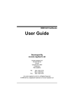
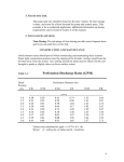
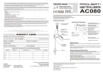
1
TI RANGE
SPECIFICATIONS
TI RANGE SPECIFICATIONSI
Commercial specifications only,pictures & drawings non contractual
.
VERSION 7.3
03 Juin. 2004
2
TI RANGE SPECIFICATIONS
SUMMARY
1.
SCOPE
4
1.1.
TI SCOPE
4
1.2.
TI RANGE
4
1.3.
CHAMBER DIMENSIONS
5
1.4.
WASHING LEVELS
6
1.5.
LOAD / UNLOADING
6
2.
UTILITIES
7
2.1.
WATER
7
2.2.
ELECTRICAL REQUIREMENTS
7
2.3.
STEAM (IF STEAM HEATING OPTION)
8
2.4.
COMPRESSED AIR
8
2.5.
DRYING AIR
8
2.6.
DRAINING
9
2.7.
VAPOUR EXTRACTION
9
3.
GENERAL CONSTRUCTION AND DESIGN
10
3.1.
GENERAL
10
3.2.
CLEANING AND DRYING PROCESS
10
4.
HYDRAULIC CIRCUIT
11
4.1.
GENERAL
11
4.2.
PIPING
11
4.3.
CHAMBER & DOOR
11
4.4.
PUMP
12
4.5.
VALVES
12
5.
DRYING SYSTEM
13
5.1.
TI MODELS
13
5.2.
TI SS MODELS
13
6.
HEATING OF THE WATER
14
6.1.
HEATING METHOD
14
6.2.
ELECTRICAL HEATING
14
6.3.
STEAM HEATING
14
7.
OUTER PANELLING, DOORS AND INSULATION
TI RANGE SPECIFICATIONSI
Commercial specifications only,pictures & drawings non contractual
.
15
VERSION 7.3
03 Juin. 2004
3
7.1.
WASHER FRAME / PANELS & DOOR
15
7.2.
STANDARD VERSION
15
7.3.
MOVEMENT OF THE DOOR
15
7.4.
DOOR LOCKING
15
7.5.
INSULATION
15
7.6.
LIFTING LUGS (OPTION)
15
8.
DETERGENT AND NEUTRALISER INTAKE
16
8.1.
METERING PUMPS & FLOW-RATE
16
8.2.
STORAGE AREA
16
8.3.
LEVEL SENSORS
17
8.4.
FLOWMETER (OPTION)
17
8.5.
ADDITIONAL METERING PUMP OPTION
17
9.
FINAL RINSE WITH PURIFIED WATER
10.
LANCER CONTROL SYSTEM
18
19
10.1.
MICRO PROCESSOR
19
10.2.
PARAMETERS
19
10.3.
ALARMS
20
10.4.
ACCESS CODES
20
10.5.
OPERATOR INTERFACE
20
10.6.
RS-232 PORT (OPTION)
20
10.7.
PRINTER AND RS-232 PORT (OPTION)
20
10.8.
VALIDATION MONITOR (OPTION)
21
10.9.
FLOW METER (OPTION)
21
10.10.
11.
LINEAR CHART RECORDER (OPTION)
22
CALIBRATION
23
11.1.
TEMPERATURE PROBES
23
11.2.
PROBE CALIBRATION
23
11.3.
THERMOCOUPLE ENTRY PORT (OPTION)
23
12.
DOCUMENTATION, QUALIFICATION & CERTIFICATES
23
12.1.
DOCUMENTATION
23
12.2.
QUALIFICATION (IQ/OQ, F.A.T, S.A.T)
24
12.3.
RISK ANALYSIS & MACHINE CONFORMITY CERTIFIED (OPTION)
25
13.
BASKETS AND ACCESSORIES
26
14.
APPENDIX
27
TI RANGE SPECIFICATIONSI
Commercial specifications only,pictures & drawings non contractual
.
VERSION 7.3
03 Juin. 2004
4
TI WASHERS SPECIFICATIONS
1.
SCOPE
1.1. TI SCOPE
TI washers have been designed to meet the growing demand of all kinds of industry (cosmetics,
petroleum, pharmaceutical, agritech, …) concerned by validatable processes and requiring washers
manufactured with materials withstanding the contact with agressive products.
1.2. TI RANGE
1.2.1.
TI washers range is built around 4 basic models corresponding to 4 chamber dimensions :
•
•
•
•
1400 TI
1600 TI
4500 TI
4800 TI
The models 1400 TI and 1600 TI are equipped with a filtered air chamber drying system, or without
drying at all (option MV14TI S/S or MV16TI S/S), the models 4500 TI and 4800 TI have no drying
system as standard.
These models are also available in double door pass-through version:
•
•
•
•
1400 TI DP
1600 TI DP
4500 TI DP
4800 TI DP
The models 1400 TI DP and 1600 TI DP are also available without drying at all.
TI RANGE SPECIFICATIONSI
Commercial specifications only,pictures & drawings non contractual
.
VERSION 7.3
03 Juin. 2004
5
1.2.2.
TI washer/dryers range is built around 4 basic models corresponding to 4 chamber dimensions :
•
•
•
•
1400 TI SS
1600 TI SS
4500 TI SS
4800 TI SS
They are equipped with a filtered air drying system (chamber and injectors).
These models are also available in double door pass-through version:
•
•
•
•
1400 TI DP SS
1600 TI DP SS
4500 TI DP SS
4800 TI DP SS
See all TI range dimensions in APPENDIX (pages 29 to 44).
1.3. CHAMBER DIMENSIONS
Major difference between the models is the chamber size. All other specifications, such as Materials,
Instrumentation, Controls, Welding, Piping are the same except if differently specified in the following
description :
INTERNAL CHAMBER DIMENSIONS (OVERALL / EFFECTIVE)
in mm
H
D
W
1400 TI/TI SS
640 / *
500 / 490
580/560
1600 TI/TI SS
855 / *
660/645
655/630
4500 TI/TI SS
1030 / *
850 / 775
850 / 775
4800 TI/TI SS
850 / *
850 / 775
1300 / 1225
* Depending on baskets
As an option, some models may have the height of the chamber extended according to 2 different
chamber elevation (option):
• option chamber stretched by 150 mm
• option chamber stretched by 250 mm
Please consult Lancer for this option.
TI RANGE SPECIFICATIONSI
Commercial specifications only,pictures & drawings non contractual
.
VERSION 7.3
03 Juin. 2004
6
1.4. WASHING LEVELS
Appropriate baskets are designed to hold the items to be washed, rinsed and dried in the chamber (to
be ordered as accessories)
TI washers are equipped with water inlets in the chamber allowing for washing from 1 to 3 levels
depending on the model:
•
•
•
•
1400 TI: 2 levels
1600 TI: 3 levels
4500 TI: 1 level
4800 TI: 1 level
See APPENDIX (pages 45 to 52) to have more information about the internal configuration of the
chamber for every model.
The water inlets are equipped with automatic connections so that in case there is no basket connected,
the water inlet remains closed.
1.5. LOAD / UNLOADING
Drop down door of the washer are equipped with gas spring and can be used as a loading / unloading
table.
A complete line of transfer carts are available for loading / unloading of racks and baskets (option).
TI RANGE SPECIFICATIONSI
Commercial specifications only,pictures & drawings non contractual
.
VERSION 7.3
03 Juin. 2004
7
2.
UTILITIES
TI washers work with the following utilities. The features of the utilities are detailed in APPENDIX (page
53).
2.1. WATER
3 water inlets allow water admission of up to 3 different water types :
• hot water
• cold water
• purified water (demineralizated or reverse osmosis treated water)
The water intakes supplied with the machine are: male 20/27 connection, 2 m. s.s. flexible supplied. As
an option, one or various water intakes can be supplied with tri-clamp connections (option CLAMP
EAU).
Hot and cold water shall be softened.
Water pressure from 2 to 6 bars (30 to 90 PSIG).
Flow from 20 to 100 l/mn (depending on the model).
As an option, the customer water loop can be piloted by the washer. See details on this option in
APPENDIX (page 60).
2.2. ELECTRICAL REQUIREMENTS
Standard electrical configurations are the following :
• 230 V. III + earth, 50 Hz.
• 400 V. III + N + earth, 50 Hz.
The required voltage shall be indicated by the customer at the order. All other voltage configurations
(ex. 480 V. III + earth, 60 Hz.) can be evaluated upon request (option).
TI RANGE SPECIFICATIONSI
Commercial specifications only,pictures & drawings non contractual
.
VERSION 7.3
03 Juin. 2004
8
2.3. STEAM (IF STEAM HEATING OPTION)
Steam allows a fast and precise water temperature adjustment
Connections on washer are male threaded fittings 15/21 (1400 & 1600 TI) or 20/27 (4500 & 4800 TI).
Hoses for connection to the washer are not provided (by Others).
Steam pressure from 2 to 6 bars (30 to 90 PSIG)
Consumption depending on model. See APPENDIX (page 53).
Strainer and steam trap have to be provided by customer
Steam heating option (option CHAUF VAP TI) is free of charge.
When heating by steam, hydraulic testing of the steam coil is possible (option TEST H VAP).
2.4. COMPRESSED AIR
Compressed air is needed for valve control and door locking.
The washer is delivered with a compressed air hose, length 1.5m with 20/27 femelle threded fitting.
Required pressure : 6 to 8 bars (90 to 116 PSIG).
Consumption according to models. See APPENDIX (page 53).
2.5. DRYING AIR
Filtered drying air intake (for the washer/dryers models) is located on the front or on the back of the
washer/dryer, according to machine configuration.
TI RANGE SPECIFICATIONSI
Commercial specifications only,pictures & drawings non contractual
.
VERSION 7.3
03 Juin. 2004
9
2.6. DRAINING
Draining is gravity type (drop drain).
Connection on machine is a tube diam. 48mm (connecting hose not provided).
Draining by pump is an option. A plastic pump is placed after the draining valve, and a polypropylene
pipe is supplied to direct the waste water to the drainage.
For this option, an exhaust for the overflow tube of the machine has to provided plus to the pump
draining exhaust.
• 1400 TI / 1600 TI : option 90010123
• 4500 TI / 4800 TI : option 90010124
Drain temperature cooldown (under 60°C) is an option.
• 1400 TI / 1600 TI : option 01060133
• 4500 TI / 4800 TI : option 01060181
2.7. VAPOUR EXTRACTION
During drying phase, hot moist air is vent out of the chamber through the chimney tube (to be
connected to an extraction network).
Extraction network must be able to suck the drying air flow.
Please refer to APPENDIX (page 53) where different connection and piloting configurations are
described (option).
TI RANGE SPECIFICATIONSI
Commercial specifications only,pictures & drawings non contractual
.
VERSION 7.3
03 Juin. 2004
10
3.
GENERAL CONSTRUCTION AND DESIGN
3.1. GENERAL
3.1.1.
Design and construction of the washers and washer/dryers are done in order to meet the most rigorous
cleaning requirements of the industrial applications. Design features and material definition conform to
the specifications listed below.
3.1.2.
All features are standard except if specifically mentioned as optional.
3.2. CLEANING AND DRYING PROCESS
3.2.1.
LANCER TI washers are specially designed to provide an adequate cleaning process using exclusively
mechanical, thermal and chemical cleaning properties.
3.2.2.
For the 1400 TI and 1600 TI models, the drying air is blown into the chamber by a powerful turbo fan.
These models are available as an option with no drying at all (option MV14TI S/S or MV16TI S/S).
3.2.3.
LANCER super drying system is available on TI SS range. This system uses filtered air, pulsed at the
same time in the chamber and directly through each injector, for a perfect drying of holloware. More
details provided in section DRYING SYSTEM page 13.
TI RANGE SPECIFICATIONSI
Commercial specifications only,pictures & drawings non contractual
.
VERSION 7.3
03 Juin. 2004
11
4.
HYDRAULIC CIRCUIT
4.1. GENERAL
4.1.1.
Hydraulic circuit is entirely built in 304L stainless steel. As an option, hydraulic circuit can be
manufactured in 316L stainless steel.
•
•
•
•
1400 TI/TISS : option 90010118
1600 TI/TISS : option 90010119
4500 TI/TISS : option 90010120
4800 TI/TISS : option 90010121
4.2. PIPING
4.2.1.
All piping is in 304L stainless steel. (see above for option 316L stainless steel).
4.2.2.
Welding is done by highly skilled and certified welders.
4.3. CHAMBER & DOOR
4.3.1.
Chamber material is stainless steel 316 L with a 220 grit finish.
4800 TI / TI SS
TI RANGE SPECIFICATIONSI
Commercial specifications only,pictures & drawings non contractual
.
VERSION 7.3
03 Juin. 2004
12
4.4. PUMP
Recirculating pumps are in stainless steel. The pump is automatically drained after each cycle.
1600 TI / TI SS
4.5. VALVES
4.5.1.
The water inlet valves, are piston valves (pneumatically controlled) in AISI 316L stainless steel with triclamp connections (20/27 male threaded fittings on water inlets out of the washer).
4.5.2.
The draining valve and the drying valve (model TI SS), are piston valves (pneumatically controlled) in
AISI 316L stainless steel with threaded connections.
4800 TI SS
TI RANGE SPECIFICATIONSI
Commercial specifications only,pictures & drawings non contractual
.
VERSION 7.3
03 Juin. 2004
13
5.
DRYING SYSTEM
5.1. TI MODELS
Ti Models (1400 & 1600) are equipped with a chamber dtying circuit only:
• External drying of the items by filtered hot air pulsed into the chamber by a centrifuge fan.
The temperature is programmable up to 110°C.
5.2. TI SS MODELS
TI SS models are equipped with a double drying circuit:
• External drying of the items by filtered hot air pulsed into the chamber by a centrifuge fan.
The temperature is programmable up to 110°C.
• Internal drying of the items (placed on the injector baskets) by filtered hot air pulsed into
the hydraulic circuit. The air is pulsed through one or two (depending on model) gas ring
compressors (turbines). The heating of the air is done by electric heating elements. The
temperature is programmable up to 110°C.
As standard, the TI SS models are equipped with a filter.
An absolute filtration of the drying air in TI SS models through prefilter and HEPA filter 99,999% is
possible (option 01060192).
The drying module, located on top of the washer can be designed so that it can be disassembled for
transport or installation purposes (option CASECD TISS).
TI RANGE SPECIFICATIONSI
Commercial specifications only,pictures & drawings non contractual
.
VERSION 7.3
03 Juin. 2004
14
6.
HEATING OF THE WATER
6.1. HEATING METHOD
Two versions for the heating of the water are available:
6.2. ELECTRICAL HEATING
Electric heating (standard): Screwed electric 316L stainless steel heating element (12 to 24 kW.
depending on model).
6.3. STEAM HEATING
As a free of charge option, the heating system for water can be provided by steam instead of
electricity. This provides a quick and accurate temperature adjustment and reduces the running costs
(particularly for the 4500 TI and 4800 TI models).
We strongly recommend this option, which uses a tri-clamped 316 L stainless steel steam exchanger
instead of the electric heating element.
As an option (option TEST H VAP), the steam coil can be hydraulically tested by an independent party
(Apave, …)
TI RANGE SPECIFICATIONSI
Commercial specifications only,pictures & drawings non contractual
.
VERSION 7.3
03 Juin. 2004
15
7.
OUTER PANELLING, DOORS AND INSULATION
7.1. WASHER FRAME / PANELS & DOOR
Washer frame is made of AISI 304. Outer panelling and door/s are made of 304L.
7.2. STANDARD VERSION
Standard version will be a cabinet mount.
7.3. MOVEMENT OF THE DOOR
The opening/closing movement of the door is eased by an ergonomic handle (two handles for 4500 TI
and 4800 TI models) and gas dampened supports.
7.4. DOOR LOCKING
Door/s are equipped with a pneumatic locking system. The door is “normally closed” (no power, no
pressure). A door opening button allows the opening of the door at the end of cycle.
7.5. INSULATION
The chamber and the outer panelling are insulated by a particle-free thermic and acoustic insulation.
7.6. LIFTING LUGS (OPTION)
As an option, lifting lugs may be necessary if the washer has to be lifted to an upper floor.
Please consult Lancer for this option.
TI RANGE SPECIFICATIONSI
Commercial specifications only,pictures & drawings non contractual
.
VERSION 7.3
03 Juin. 2004
16
8.
DETERGENT AND NEUTRALISER INTAKE
8.1. METERING PUMPS & FLOW-RATE
All TI / TI SS washers are fitted with 2 metering pumps for proper dosing of neutraliser and detergent.
pump 280ml/mn
Metering pumps rate is 280 up to 1000 ml/min according to model.
8.2. STORAGE AREA
The washers 1400 TI and 1600 TI have a storage system for two 10 liters chemical tanks (dimensions
maxi. H 320 x W 230 x D 200 mm).
1400 TI / 1600 TI
Two emptying tanks H 320 x W 230 x D 200 mm are provided with the washers 1400 TI and 1600 TI.
In case of tanks exceeding the above dimensions, the tanks will have to be located out of the machine
(free of charge option).
TI RANGE SPECIFICATIONSI
Commercial specifications only,pictures & drawings non contractual
.
VERSION 7.3
03 Juin. 2004
17
8.3. LEVEL SENSORS
All TI / TI SS are fitted with level sensors (for tanks dimensions H 320 x W 230 x D 200 mm) to prevent
pumping in the absence of liquid.
Visual and audible alarm warns in case of lack of chemicals.
In case of tanks exceeding the above dimensions, the level sensors can be adapted to specific tanks
(option).
Please consult Lancer for this option.
8.4. FLOWMETER (OPTION)
If the washer is equipped with the Validation Monitor (option MONVAL), it is possible to have a
flowmeter system (option 01060231) which allows a precise measure of detergent and/or acid intakes
(and compares it to a reference value).
8.5. ADDITIONAL METERING PUMP (OPTION)
In option, the TI and TI SS models can be equipped with additional metering pumps (1 up to 3) for
specific applications (i.e. cosmetic industry). This option includes associated level sensor.
The number of additional metering pumps depends on the model and options of the washer.
•
•
•
•
•
dosing pump 30ml option 90010208
dosing pump 280ml option 90010209
dosing pump 1000ml option 90010130
dosing pump 280ml if option Monval option 90010132
dosing pump 1000ml if option Monval option 90010133
TI RANGE SPECIFICATIONSI
Commercial specifications only,pictures & drawings non contractual
.
VERSION 7.3
03 Juin. 2004
18
9.
FINAL RINSE WITH PURIFIED WATER
The final rinse is carried out with purified water using the main recirculation pump.
A conductivity meter (in option), permits to control the water quality at the end of the last rinsing. The
conductivity meter will also give useful indications for the validation team.
• POLYMETRON-ZELLWEGER conductivity meter, with screwed sensor, cell constant 0,01
(option 90010229).
This option includes two non return valves welded on chamber which close additive circuits at the end
of each additive intake.
If the washer is equipped with more than 2 additive lines (see page 17), a non return valve welded on
chamber can be provided on each additional additive line.
• Non return valve on additive line option 90010230
TI RANGE SPECIFICATIONSI
Commercial specifications only,pictures & drawings non contractual
.
VERSION 7.3
03 Juin. 2004
19
10. LANCER CONTROL SYSTEM
Display of the LANCER
Control System
Keypad of the LANCER
Control System
Door opening button
Emergency stop button
Conductivity meter
(option)
Printer (option)
Main switch
10.1. MICRO PROCESSOR
A micro processor with 40 adjustable programmes ensures the TI washer control. The control system is
mounted in a 400 mm. width stainless steel module permitting to fit not only the microprocessor but
also the different available options (printer, conductivity meter, chart recorder,…)
10.2. PARAMETERS
Control system can to set up different parameters for each storable program such as :
•
•
•
•
•
•
•
•
•
number of phases for the program (pre wash, wash,
neutralizing rinse...)
duration for each phase
water inlet selection for each phase
temperature for pre-wash, wash and final rinse
1st and 2nd additive intake
drying time
drying temperature (TI SS only)
customised wash protocols are available upon request (memory creation option
01060132 or memory copy option 90010156)
TI RANGE SPECIFICATIONSI
Commercial specifications only,pictures & drawings non contractual
.
VERSION 7.3
03 Juin. 2004
20
10.3. ALARMS
The LANCER control system has an extensive number of alarms such as lack of additives, filling
pressure, high level of conductivity (optional), drying temperature (for drying models), cycle
interruption, water level as well as being completely self-diagnostic.
10.4. ACCESS CODES
Three levels of codes allow the access to different functions of the control system :
• supervisor code allows access to every functions
• technician code allows access to test, calibration and start functions
• operator code allows access to start functions
10.5. OPERATOR INTERFACE
Operator interface consists of a 2 lines display with a numerical keyboard et 4 function keys.
10.6. RS-232 PORT (OPTION)
To enable the washer to communicate with external devices, a RS-232 can be provided on the washer
(option 90010155).
10.7. PRINTER AND RS-232 PORT (OPTION)
To ensure cycle documentation, information can be printed on a impact printer. (option 01060207)
This printer gives documented evidence of the cleaning process including cycle parameters, operator
number, time of program start, phase duration, probe temperature during each phase.
This option includes also a RS-232 on the main board of the washer.
TI RANGE SPECIFICATIONSI
Commercial specifications only,pictures & drawings non contractual
.
VERSION 7.3
03 Juin. 2004
21
10.8. VALIDATION MONITOR (OPTION)
TI washer with LANCER control system can be fitted in option with a Validation Monitor (option
01060195).
This Validation Monitor has its own electronic board and its own probes to check and validate every
parameter of the cycle of the washing cycle.
Its printer gives documented evidence of the cleaning process including date, machine number, time of
program start, phase duration, probe temperature at each phase of the cycle when water is heated,
detergent and acid intake, etc.
The Validation Monitor option includes the impact printer and the RS 232 connection.
10.9. FLOW METER (OPTION)
When the washer is equipped with the Validation Monitor (option 01060195), flow-meters allow to
measure the exact quantity of chemical taken by the machine during the cycle.
This information is sent to the Validation Monitor which compares it to the theoretical values
programmed for the cycle.
• Flow-meter if option Validation Monitor (option 90010210)
TI RANGE SPECIFICATIONSI
Commercial specifications only,pictures & drawings non contractual
.
VERSION 7.3
03 Juin. 2004
22
10.10.
LINEAR CHART RECORDER (OPTION)
A linear chart recorder 144x144 mm. can also be mounted as an option to keep a record of the cycle
parameters.
Several type of chart recorders are available :
• 1 pen chart recorder (option EN ANA 1V) with 1 temperature sensor.
• 2 pen chart recorder (option EN ANA 2 V) with 1 temperature sensor
and 1 free track.
• 3 tracks digital chart recorder, paperless (option ENR NUM 3V) with 1
temperature sensor and 2 free tracks. This chart recorder creates a hard
copy of the records on a floppy disk and is supplied with a software to
read and print the database on an external PC.
• 6 tracks digital chart recorder, paperless (option ENR NUM 6V) with 1
temperature sensor and 5 free tracks. This chart recorder creates a hard
copy of the records on a floppy disk and is supplied with a software to
read and print the database on an external PC.
The parameters that can be recorded in the free tracks are:
•
•
•
•
•
•
Track for temperature (with Pt-1000 probe) (option 90010112)
Track for pump pressure (with pressure transmitter) (option 90010113)
Track for pump pressure (if option Monval) (option 90010207)
Track for dosing pump (with pressure transmitter) (option 90010114)
Track for dosing pump (if option Monval) (option 90010206)
Track for conductivity (if option conductivity meter) (option 90010116)
The sensors linked to the chart recorder are independent from those used for cycle regulation.
TI RANGE SPECIFICATIONSI
Commercial specifications only,pictures & drawings non contractual
.
VERSION 7.3
03 Juin. 2004
23
11. CALIBRATION
11.1. TEMPERATURE PROBES
The Pt-1000 temperature probe/s (1 to 3 depending on model) are independent and can be adjusted
according to pattern probes.
11.2. PROBE CALIBRATION
A tri-clamp dismounting system for these probes allows a calibration in an outside thermostatic bath.
11.3. THERMOCOUPLE ENTRY PORT (OPTION)
To enable the washer to be validated by using external calibrated probes, as an option, validation ports
on top or bottom of chamber can be provided.
• Top entry port
• Bottom entry port
• Top & bottom entry port
option 01060171
option 01060172
option 01060173
12. DOCUMENTATION, QUALIFICATION & CERTIFICATES
12.1. DOCUMENTATION
One complete set of documentation according to Lancer Standards is given with the washer including:
•
•
•
•
•
•
•
•
installation manual
user's manual
technical manual
maintenance manual
electrical diagram
P I D (see APPENDIX page 55)
spare parts list
exploded view
TI RANGE SPECIFICATIONSI
Commercial specifications only,pictures & drawings non contractual
.
VERSION 7.3
03 Juin. 2004
24
12.2. QUALIFICATION (IQ/OQ, F.A.T, S.A.T)
IQ :
OQ :
FAT :
SAT :
Installation Qualification
Operating Qualification
Factory Acceptance Test
Site Acceptance Test
As an option, the TI washers can be qualified at the factory and on site
12.2.1. IQ/OQ documentation and FAT protocol (option 90010184)
As an option, the TI washers can be qualified at the factory according to a IQ/OQ protocol.
This filled protocol is given with the documentation set of the machine.
A blank copy of this protocol is also given so as to realize, by yourself on site, the same protocol (SAT
protocole).
12.2.2. IQ/OQ documentation and FAT protocol in presence of the customer (option 90010134)
As an option, the TI washers can be qualified at the factory in presence of the customer according to a
IQ/OQ protocol.
This filled protocol is given with the documentation set of the machine.
A blank copy of this protocol is also given so as to realize, by yourself on site, the same protocol (SAT
protocole).
12.2.3. IQ/OQ documentation and SAT protocol (option 90010183) ou IQ/OQ documentation and SAT
protocol with MONVAL (option 90010182)
As an option, the TI washers can be qualified on site, in presence of a LANCER technicien, according
to the SAT LANCER protocol.
This option is only available in France (for your country, please ask your local representative)
TI RANGE SPECIFICATIONSI
Commercial specifications only,pictures & drawings non contractual
.
VERSION 7.3
03 Juin. 2004
25
12.3. RISK ANALYSIS & MACHINE CONFORMITY CERTIFIED (OPTION)
Several options are available so as to certifie TI washers.
12.3.1.
Machine conformity certified by a notified body (option)
As an option, TI washers can be certified by a notified body (Apave, …).
Please consult Lancer for this option.
12.3.2.
Risk analysis & Machine conformity certified by a notified body (option)
As an option, TI washers can be checked and certified by a notified body (Apave, …).
Please consult Lancer for this option.
TI RANGE SPECIFICATIONSI
Commercial specifications only,pictures & drawings non contractual
.
VERSION 7.3
03 Juin. 2004
26
13. BASKETS AND ACCESSORIES
Lancer has designed a standard line of racks to answer most of the washing needs (please refer to
APPENDIX page 56) :
• the basic basket (PST) allows to wash parts with large neck which can be laid flat. This
basket is only used on the lower level of the washer to benefit from the spraying of the
lower chamber washing arm.
• the basic basket + washing arm (PSBT) is designed the same way as the PS but it is
fitted with a washing arm. This feature allows to locate it on the upper level of the chamber
(accessory not available for models 4500 and 4800).
• the jet basket allows to wash parts with small neck. Jets can be fitted with spherical
spreader for the washing of large containers. Height and diameter of the jets have to be
adapted to the part geometry to ensure an optimum result.
Baskets can also be designed for specific application such as :
• tube washing. Our tube baskets allows to wash long tubes thanks to helicoidal supports.
• valve washing. Our valve baskets have distributing line with different clamp sizes to
connect the valves.
• special set of parts washing. Special baskets can be designed to fit the more complex
geometry. They can also take into account devoted location of parts (for instance the
pump body and its piston side by side).
Accessories can help to load and maintain parts onto baskets :
• mesh baskets type ST / LT can contain small dimension parts.
• grid can hold large parts vertically
The main technical characteristics of TI baskets are the following :
• Polyacetal wheels
• injectors threaded onto manifolds
• Stainless steel construction
TI RANGE SPECIFICATIONSI
Commercial specifications only,pictures & drawings non contractual
.
VERSION 7.3
03 Juin. 2004
27
TI RANGE SPECIFICATIONS
APPENDIX
14. APPENDIX
•
APPENDIX 1: DIMENSIONS – 1400 TI
29
•
APPENDIX 1: DIMENSIONS – 1400 TI SS
30
•
APPENDIX 1: DIMENSIONS – 1400 TI DP
31
•
APPENDIX 1: DIMENSIONS – 1400 TI DPSS
32
•
APPENDIX 1: DIMENSIONS – 1600 TI
33
•
APPENDIX 1: DIMENSIONS – 1600 TI SS
34
•
APPENDIX 1: DIMENSIONS – 1600 TI DP
35
•
APPENDIX 1: DIMENSIONS – 1600 TI DPSS
36
•
APPENDIX 1: DIMENSIONS – 4500 TI
37
•
APPENDIX 1: DIMENSIONS – 4500 TI SS
38
•
APPENDIX 1: DIMENSIONS – 4500 TI DP
39
•
APPENDIX 1: DIMENSIONS – 4500 TI DPSS
40
•
APPENDIX 1: DIMENSIONS – 4800 TI
41
•
APPENDIX 1: DIMENSIONS – 4800 TI SS
42
•
APPENDIX 1: DIMENSIONS – 4800 TI DP
43
•
APPENDIX 1: DIMENSIONS – 4800 TI DPSS
44
•
APPENDIX 2: CHAMBER – 1400 TI / TI SS
45
TI RANGE SPECIFICATIONSI
Commercial specifications only,pictures & drawings non contractual
.
VERSION 7.3
03 Juin. 2004
28
•
APPENDIX 2: CHAMBER – 1400 TI DP / TI DPSS
46
•
APPENDIX 2: CHAMBER – 1600 TI / TI SS
47
•
APPENDIX 2: CHAMBER – 1600 TI DP / TI DPSS
48
•
APPENDIX 2: CHAMBER – 4500 TI / TI SS
49
•
APPENDIX 2: CHAMBER – 4500 TI DP / TI DPSS
50
•
APPENDIX 2: CHAMBER – 4800 TI / TI SS
51
•
APPENDIX 2: CHAMBER – 4800 TI DP / TI DPSS
52
•
APPENDIX 3: UTILITIES
53
•
APPENDIX 4: VAPOUR EXTRACTION
54
•
APPENDIX 5: PIPING & AND INSTRUMENT DIAGRAM (P&ID)
55
•
APPENDIX 6: BASKETS AND ACCESSORIES
56
•
APPENDIX 7: IQ/OQ PROTOCOL (OPTION)
59
•
APPENDIX 8: LOOP PILOTING (OPTION PILOT PPI)
60
•
APPENDIX 9: SUMMARY FOR STANDARDS & OPTIONS
61
TI RANGE SPECIFICATIONSI
Commercial specifications only,pictures & drawings non contractual
.
VERSION 7.3
03 Juin. 2004
29
•
APPENDIX 1: DIMENSIONS – 1400 TI
TI RANGE SPECIFICATIONSI
Commercial specifications only,pictures & drawings non contractual
.
VERSION 7.3
03 Juin. 2004
30
•
APPENDIX 1: DIMENSIONS – 1400 TI SS
TI RANGE SPECIFICATIONSI
Commercial specifications only,pictures & drawings non contractual
.
VERSION 7.3
03 Juin. 2004
31
•
APPENDIX 1: DIMENSIONS – 1400 TI DP
TI RANGE SPECIFICATIONSI
Commercial specifications only,pictures & drawings non contractual
.
VERSION 7.3
03 Juin. 2004
32
•
APPENDIX 1: DIMENSIONS – 1400 TI DPSS
TI RANGE SPECIFICATIONSI
Commercial specifications only,pictures & drawings non contractual
.
VERSION 7.3
03 Juin. 2004
33
•
APPENDIX 1: DIMENSIONS – 1600 TI
TI RANGE SPECIFICATIONSI
Commercial specifications only,pictures & drawings non contractual
.
VERSION 7.3
03 Juin. 2004
34
•
APPENDIX 1: DIMENSIONS – 1600 TI SS
TI RANGE SPECIFICATIONSI
Commercial specifications only,pictures & drawings non contractual
.
VERSION 7.3
03 Juin. 2004
35
•
APPENDIX 1: DIMENSIONS – 1600 TI DP
TI RANGE SPECIFICATIONSI
Commercial specifications only,pictures & drawings non contractual
.
VERSION 7.3
03 Juin. 2004
36
•
APPENDIX 1: DIMENSIONS – 1600 TI DPSS
TI RANGE SPECIFICATIONSI
Commercial specifications only,pictures & drawings non contractual
.
VERSION 7.3
03 Juin. 2004
37
•
APPENDIX 1: DIMENSIONS – 4500 TI
TI RANGE SPECIFICATIONSI
Commercial specifications only,pictures & drawings non contractual
.
VERSION 7.3
03 Juin. 2004
38
•
APPENDIX 1: DIMENSIONS – 4500 TI SS
TI RANGE SPECIFICATIONSI
Commercial specifications only,pictures & drawings non contractual
.
VERSION 7.3
03 Juin. 2004
39
•
APPENDIX 1: DIMENSIONS – 4500 TI DP
TI RANGE SPECIFICATIONSI
Commercial specifications only,pictures & drawings non contractual
.
VERSION 7.3
03 Juin. 2004
40
•
APPENDIX 1: DIMENSIONS – 4500 TI DPSS
TI RANGE SPECIFICATIONSI
Commercial specifications only,pictures & drawings non contractual
.
VERSION 7.3
03 Juin. 2004
41
•
APPENDIX 1: DIMENSIONS – 4800 TI
TI RANGE SPECIFICATIONSI
Commercial specifications only,pictures & drawings non contractual
.
VERSION 7.3
03 Juin. 2004
42
•
APPENDIX 1: DIMENSIONS – 4800 TI SS
TI RANGE SPECIFICATIONSI
Commercial specifications only,pictures & drawings non contractual
.
VERSION 7.3
03 Juin. 2004
43
•
APPENDIX 1: DIMENSIONS – 4800 TI DP
TI RANGE SPECIFICATIONSI
Commercial specifications only,pictures & drawings non contractual
.
VERSION 7.3
03 Juin. 2004
44
•
APPENDIX 1: DIMENSIONS – 4800 TI DPSS
TI RANGE SPECIFICATIONSI
Commercial specifications only,pictures & drawings non contractual
.
VERSION 7.3
03 Juin. 2004
45
•
APPENDIX 2: CHAMBER – 1400 TI / TI SS
TI RANGE SPECIFICATIONSI
Commercial specifications only,pictures & drawings non contractual
.
VERSION 7.3
03 Juin. 2004
46
•
APPENDIX 2: CHAMBER – 1400 TI DP / TI DPSS
TI RANGE SPECIFICATIONSI
Commercial specifications only,pictures & drawings non contractual
.
VERSION 7.3
03 Juin. 2004
47
•
APPENDIX 2: CHAMBER – 1600 TI / TI SS
TI RANGE SPECIFICATIONSI
Commercial specifications only,pictures & drawings non contractual
.
VERSION 7.3
03 Juin. 2004
48
•
APPENDIX 2: CHAMBER – 1600 TI DP / TI DPSS
TI RANGE SPECIFICATIONSI
Commercial specifications only,pictures & drawings non contractual
.
VERSION 7.3
03 Juin. 2004
49
•
APPENDIX 2: CHAMBER – 4500 TI / TI SS
TI RANGE SPECIFICATIONSI
Commercial specifications only,pictures & drawings non contractual
.
VERSION 7.3
03 Juin. 2004
50
•
APPENDIX 2: CHAMBER – 4500 TI DP / TI DPSS
TI RANGE SPECIFICATIONSI
Commercial specifications only,pictures & drawings non contractual
.
VERSION 7.3
03 Juin. 2004
51
•
APPENDIX 2: CHAMBER – 4800 TI / TI SS
TI RANGE SPECIFICATIONSI
Commercial specifications only,pictures & drawings non contractual
.
VERSION 7.3
03 Juin. 2004
52
•
APPENDIX 2: CHAMBER – 4800 TI DP / TI DPSS
TI RANGE SPECIFICATIONSI
Commercial specifications only,pictures & drawings non contractual
.
VERSION 7.3
03 Juin. 2004
53
•
APPENDIX 3: UTILITIES
1400 & 1600
Utilities
Characteristics
Consumptions
Connections
1400 TI
1400 TI SS
1600 TI
1600 TI SS
Water (1)
pressure : 2 to 6 bar
flow : 20 to 100l/min
Threaded 20/27
20L
20L
25L
25L
Compressed air
pressure : 6 to 8 bar
Filtration : 5µ
Threaded 20/27
70L
80L
70L
80L
Steam
pressure : 2 to 6 bar
Threaded 15/21
35kg
35kg
40kg
40kg
Electricity
Voltage :
400tri+N ou 230tri 50Hz
Bare cable
11kW*
14,5kW**
16kW*
16kW**
11kW*
21kW**
16kW*
21kW**
Drying air
Athmospheric
tube Ø 76
200m3/h
250m3/h
200m3/h
250m3/h
By gravity
tube Ø 48
50L/min
50l/min
80l/min
80l/min
Characteristics
Raccordements
Drain
4500 & 4800
Utilities
Consumptions
4500 TI
4500 TISS
4800 TI
4800 TISS
Water (1)
pressure : 2 to 6 bar
flow : 20 to 100l/min
Threaded 20/27
100L
100L
125L
125L
Compressed air
pressure : 6 to 8 bar
Filtration : 5µ
Threaded 20/27
70L
90L
70L
90L
Steam
pressure : 2 to 6 bar
Threaded 20/27
70kg
70kg
70kg
70kg
Electricity
Voltage :
400tri+N ou 230tri 50Hz
Bare cable
6kW*
30kW**
17,5kW*
30kW**
6kW*
30kW**
17,5kW*
30kW**
Drying air
Athmospheric
tube Ø 76
/
200m3/h
/
200m3/h
By gravity
tube Ø 48
80L/min
80L/min
80L/min
80L/min
Drain
(1) : for each filling phase
* total consumption for a steam heating washer
** total consumption for an electrical heating washer
TI RANGE SPECIFICATIONSI
Commercial specifications only,pictures & drawings non contractual
.
VERSION 7.3
03 Juin. 2004
54
•
APPENDIX 4: VAPOUR EXTRACTION
Principle :
A continuous extraction is not recommended because it increases the water heating time by sucking
calories into the chamber.
Two configurations are advised :
•
Double speed extractor (to be provided by customer)
The extractor in high speed sucks the vapours during the drying. The extractor in low speed during
the other cycle phases does not suck calories into the chamber and does not increase the water
heating duration.
As an option (option 90010084), the washer control system closes a relay during the drying phase
to switch the extractor in high speed mode (extractor piloting to be provided by customer).
In order to avoid any condensation back flow on the top of the washer, a drain system on the line
is recommended.
•
Single speed extractor and hood (to be provided by customer)
A hood located above the chimney washer sucks the vapours during the drying. The hood being
not directly connected to the chamber, there is no heating loss and a single speed extractor can be
used.
In order to avoid any condensation back flow on the top of the washer, a drain system on the hood
is recommended.
TI RANGE SPECIFICATIONSI
Commercial specifications only,pictures & drawings non contractual
.
VERSION 7.3
03 Juin. 2004
55
•
APPENDIX 5: PIPING & AND INSTRUMENT DIAGRAM (P&ID)
TI RANGE SPECIFICATIONSI
Commercial specifications only,pictures & drawings non contractual
.
VERSION 7.3
03 Juin. 2004
56
•
APPENDIX 6: BASKETS AND ACCESSORIES
BASKET “PST” AND ACCESSORIES
In order to wash items in "ST" or "LT" type
baskets, place the baskets on the "PST" (basic
rack) or "PSBT" (basic rack with spray arm) after
removing one or more "GS" (support grilles).
Check that the basket is correctly fitted on the rods
of the rack designed for that purpose. Reinstall the
grilles for any washing operation that does not
require the use of "ST" or "LT" type baskets.
Remark : The "PST" should only be positioned at the bottom level of the washer chamber where washing action is
provided by the lower spray arm. The "PSBT" can be positioned on any level.
BASKET “PS” AND ACCESSORIES
It is extremely important that the items to be
washed are prevented from moving in order to
obtain correct cleaning and to avoid breakage of
fragile items. Items that can be easily moved or
knocked over when loaded on the "PST" or
"PSBT" rack should be secured in place. The
"GC" hold down screen should be used for "PST"
or "PSBT" racks. The "GCI" hold down screen
should be used for injector racks.
Remark : The "PST" should only be positioned at the bottom level of the washer chamber where washing action is
provided by the lower spray arm. The "PSBT" can be positioned on any level.
TI RANGE SPECIFICATIONSI
Commercial specifications only,pictures & drawings non contractual
.
VERSION 7.3
03 Juin. 2004
57
BASKET “PSBT” AND ACCESSORIES
In order to wash items on a "PL" type
basket (for cleaning slides), place the
baskets on the "PST" (basic rack) or
"PSBT" (basic rack with spray arm) after
removing one or more "GS" (support
grilles). Check that the basket is correctly
fitted on the rods of the rack designed for
that purpose. Reinstall the grilles for any
washing operation that does not require
the use of "PL" type baskets.
Remark : The "PST" should only be positioned at the bottom level of the washer chamber where washing action is
provided by the lower spray arm. The "PSBT" can be positioned on any level.
JET RACK AND ACCESSORIES
In the case of washing items with small diameter openings such as volumetric flasks, it is very important that the flow
rate of the injectors used must be lower than the flow capacity of the flasks to be washed in order to avoid a gradual
filling of the flasks during the washing cycle. If the diameter of the opening is too small to allow the water to escape
from around the injector the mechanical action of the injector can be absorbed by the water contained in the
glassware giving poor cleaning results. It is imperative to use baskets with injectors of proper diameter and, above all,
to secure lightweight items with a "GCI" hold down screen.
TI RANGE SPECIFICATIONSI
Commercial specifications only,pictures & drawings non contractual
.
VERSION 7.3
03 Juin. 2004
58
CUSTOM RACK
TI RANGE SPECIFICATIONSI
Commercial specifications only,pictures & drawings non contractual
.
VERSION 7.3
03 Juin. 2004
59
•
APPENDIX 7: IQ/OQ PROTOCOL (option)
F.A.T FOR TI RANGE :
ITES042&-Summary
LIST OF TESTS PERFORMED AT FACTORY (F.A.T) IN THE IQ/OQ PROTOCOL ITES042& :
TEST BENCH PARAMETERS :
• To check the parameters of the tests (water pressure, voltage …).
DIMENSIONS CHECKING :
• To check the external and internal dimensions in comparison with the installation
drawings.
SENSORS CALIBRATION :
• To check the calibration of temperature probes, of pressure transmitters and flowmeters.
PUMP AND TURBINES ROTATING WAYS :
• To check the functioning of the recycling pump and the drying turbines.
DOSING PUMPS CHECKING :
• To check the functioning of the dosing pumps and to measure their flow rate.
OUTPUT TEST :
• To check the outputs of the main electronic board.
DOOR SWITCH / DOOR LOCKING :
• To check the functioning of the door switch and of the door locking device.
HEATING TEST :
• To check the functioning of the heating.
EMPTYING TEST :
• To check the functioning of the emptying.
MAIN BOARD ALARMS :
• To simulate faults and check all the alarms from the main electronic board.
NORMAL CYCLE:
• To perform a cycle where all the parameters have a different value in order to check a
complete cycle.
Note : When there is a Validation Monitor, another protocol is added. It is the ITES009& document
where all the Validation Monitor alarms are tested.
TI RANGE SPECIFICATIONSI
Commercial specifications only,pictures & drawings non contractual
.
VERSION 7.3
03 Juin. 2004
60
•
APPENDIX 8: LOOP PILOTING (option pilot ppi)
•
Loop valve piloting by compressed air (option 90010122)
The washer control system opens the washer inlet valve and in the same time opens
pneumatically the loop valve
•
Loop valve piloting by relay (option 90010084)
The washer control system opens the washer inlet valve and in the same time closes a relay. The
closing of this relay is taken into account by the PCL controlling the loop. The PLC opens then the
loop valve.
If loop is not available, the loop PLC does not open the loop valve. A temporisation allows to wait
the opening authorisation. Should the waiting be too long, a filling fault alarm occurs.
TI RANGE SPECIFICATIONSI
Commercial specifications only,pictures & drawings non contractual
.
VERSION 7.3
03 Juin. 2004
61
•
APPENDIX 9: SUMMARY FOR STANDARDS & OPTIONS
CONFIGURATION
Chamber & door in 316L stainless steel
pages
Standard
11
Chamber elevation +150mm
Option (consult Lancer)
5
Chamber elevation +250mm
Option (consult Lancer)
5
Standard
11
Hydraulic circuit in 304L stainless steel (recirculation pump & piping) 1400TI/TISS
Option 90010118
11
Hydraulic circuit in 304L stainless steel (recirculation pump & piping) 1600TI/TISS
Option 90010119
11
Hydraulic circuit in 304L stainless steel (recirculation pump & piping) 4500TI/TISS
Option 90010120
11
Hydraulic circuit in 304L stainless steel (recirculation pump & piping) 4800TI/TISS
Option 90010121
11
Option CLAMP EAU
7
Standard
9
Draining by lifting pump 1400/1600 TI
Option 90010123
9
Draining by lifting pump 4500/4800 TI
Option 90010124
9
Drain cooling 1400/1600 TI
Option 01060133
9
Drain cooling 4500/4800 TI
Option 01060181
9
Vapour exhaust chimney
Standard
9
Door gas spring
Standard
6
Additive tank area (Models 1400/1600 TI/TISS/TIDP/TIDPSS)
Standard
16
Level sensors for 2 tanks
Standard
17
Option (consult Lancer)
17
Standard
16
Option
17
Standard
14
Water heating by steam coil
Option 90010127
14
Hydraulic test of steam coil
Option 90010128
14
Standard
13
Removable drying box
Option CASECD TISS
13
Lifting lugs
Option (consult Lancer)
15
No drying device 1400 TI
Option MV14TI S/S
4
No drying device 1600 TI
Option MV16TI S/S
4
Drying HEPA filter (Models TISS / TIDPSS)
Option 01060192
13
Specific memory (creation)
Option 01060132
19
Specific memory (copy)
Option 90010156
19
Hydraulic circuit in 304L stainless steel (recirculation pump & piping)
Tri clamp fiiting on water inlet
Sanitary gravity drain (with 316L stainless steel valve)
Specificif dip tubes (with level sensors)
Dosing pumps for 2 addtives
Additional dosing pump with level sensor (1 up to 3)
Water heating by immersion heaters
Adjustable drying temperature (Models with drying)
TI RANGE SPECIFICATIONSI
Commercial specifications only,pictures & drawings non contractual
.
VERSION 7.3
03 Juin. 2004
62
INSTRUMENTATION
pages
Microprocessor
Standard
19
Probes Pt-1000
1 up to 3 according to model
23
Emergency stop button(s)
Standard
19
Validation Monitor (Monval)
Option 01060195
21
Impact printer
Option 01060207
20
RS 232 plug
Option 90010155
20
Flowmeter if option Monval (1 up to 4)
Option 90010210
21
Conductivity meter Polymétron-Zellweger
Option 90010229
18
Non return valve on additive line
Option 90010230
17
Pen chart recorder 1 track (paper)
Option ENR ANA 1V
22
Pen chart recorder 2 track (paper)
Option ENR ANA 2V
22
Digital 3 chart recorder (paperless)
Option ENR NUM 3V
22
Digital 6 chart recorder (paperless)
Option ENR NUM 6V
22
Temperature track for recorder
Option 90010112
22
Pump pressure track for recorder
Option 90010113
22
Pump pressure track for recorder if option Monval
Option 90010207
22
Dosing pump pressure track for recorder
Option 90010114
22
Dosing pump pressure track for recorder if option Monval
Option 90010206
22
Conductivity track for recorder if option conductivity meter
Option 90010116
22
Thermocouple entry port - top
Option 01060171
23
Thermocouple entry port - bottom
Option 01060172
23
Thermocouple entry port – top & bottom
Option 01060173
23
Water loop piloting by compressed air
Option 90010122
60
Water loop piloting by volt free contact
Option 90010084
60
Vapour extraction piloting by volt free contact
Option 90010084
54
QUALIFICATION / CONFORMITY
pages
Documentation IQ/OQ and protocol FAT
Option 90010184
24
Documentation IQ/OQ and protocol FAT in présence of customer
Option 90010134
24
Documentation IQ/OQ and protocol SAT
Option 90010183
24
Documentation IQ/OQ and protocol SAT if option Monval
Option 90010182
24
Machine conformity verification
Option (consult Lancer)
25
Risk analysis and machine conformity verification
Option (consult Lancer)
25
TI RANGE SPECIFICATIONSI
Commercial specifications only,pictures & drawings non contractual
.
VERSION 7.3
03 Juin. 2004
63
LANCER France
30 Bd de l’Industrie
- Z.I. PAHIN –
31170 TOURNEFEUILLE
FRANCE
Tél : +33 (0)5 61 15 11 11
Fax : +33 (0)5 61 15 16 16
LANCER USA INC.
140 State Road 419
Winter Springs
Florida 32708
USA
Phone : +1 407 327 8488
Fax : +1 407 327 1229
LANCER UK LTD
1 Pembroke Avenue Waterbeach
Cambridge
CB5 9QR
UK
Phone : +44 1 223 861 665
Fax : +44 1 223 861 990
LANCER HOLLAND BV
Postbus 33
6659 ZG
Wamel
NETHERLANDS
Phone : +31 487 51 80 88
Fax : +31 487 51 79 78
Document non contractuel. LANCER se réserve le droit de modifier, à tous moments, ses modèles en vue de leur amélioration.
TI RANGE SPECIFICATIONSI
Commercial specifications only,pictures & drawings non contractual
.
VERSION 7.3
03 Juin. 2004