1
Adding/Removing Internal Components
4–11
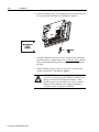
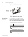
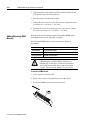
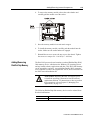
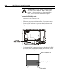
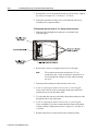
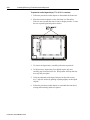
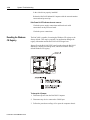
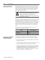
5. Remove the DOC from its socket. Pull the device straight up. Be
careful not to bend or damage the DOC pins.
ATTENTION: Make sure to hook only the DOC with
the extraction tool, and not the socket located directly
below the DOC. Do not pull the socket from the printed
circuit board assembly. Irreparable damage will result.
6. Store the DOC memory in an anti-static wrapper.
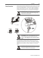
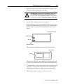
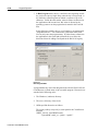
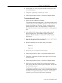
7. Before installing the new replacement DOC memory chip, be sure it
is properly oriented with regard to the chip socket. On one end of
the DOC chip is a beveled corner, an inked notch, and a dot (see
below).
DiskOnChip Device
Inked notch
Dot
Beveled corner
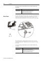
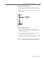
The chip socket itself contains a notch on one end (see below).
Chip Socket
Notch
Align the end of the DOC chip containing the inked notch, dot and
beveled corner with the end of the chip socket containing the notch.
8. To install the DOC memory chip, carefully align all the pins with the
chip socket. Gently push the pins into the socket until the chip is
seated against the socket base. Make sure not to bend any pins.
9. Follow the procedures on Page 4-3 to close the chassis.
Publication 6182-UM001D-EN-P