Download PMAC-NC Pro2 Software Reference Manual
Transcript
^ SOFTWARE REFERENCE 1 ^2 PMAC-NC Pro2 ^3 Software Reference Manual ^4 3Ax-NC32V5-xSxx ^5 August 10, 2012 Single Source Machine Control Power // Flexibility // Ease of Use 21314 Lassen Street Chatsworth, CA 91311 // Tel. (818) 998-2095 Fax. (818) 998-7807 // www.deltatau.com Copyright Information © 2010 Delta Tau Data Systems, Inc. All rights reserved. This document is furnished for the customers of Delta Tau Data Systems, Inc. Other uses are unauthorized without written permission of Delta Tau Data Systems, Inc. Information contained in this manual may be updated from time-to-time due to product improvements, etc., and may not conform in every respect to former issues. To report errors or inconsistencies, call or email: Delta Tau Data Systems, Inc. Technical Support Phone: (818) 717-5656 Fax: (818) 998-7807 Email: [email protected] Website: http://www.deltatau.com Operating Conditions All Delta Tau Data Systems, Inc. motion controller products, accessories, and amplifiers contain static sensitive components that can be damaged by incorrect handling. When installing or handling Delta Tau Data Systems, Inc. products, avoid contact with highly insulated materials. Only qualified personnel should be allowed to handle this equipment. In the case of industrial applications, we expect our products to be protected from hazardous or conductive materials and/or environments that could cause harm to the controller by damaging components or causing electrical shorts. When our products are used in an industrial environment, install them into an industrial electrical cabinet or industrial PC to protect them from excessive or corrosive moisture, abnormal ambient temperatures, and conductive materials. If Delta Tau Data Systems, Inc. products are exposed to hazardous or conductive materials and/or environments, we cannot guarantee their operation. REVISION HISTORY REV. 1 2 3 4 5 6 7 8 9 10 11 12 13 DESCRIPTION UPDATED AUTOPILOT UTILITY CHAPTER REMOVED TOUCH PROBING SECTION REMOVED WINDOWS 2000 SYSTEM REQ. ADDED G05.1 & G103, REMOVED M-CODE INTEG. ADDED NEW SCREENSHOTS, PP. 8-9 REVISED NC BUFFERS SECTION, P. 18 REVISED PARAMETRIC VARIABLES, PP. 163-164 UPDATED NCUI32 REFS TO PMAC-NC PRO2 (ALL) NEW SYSTEM BACKUP CHAPTER NEW ALT+FUNCTION KEY CHAPTER NEW SCREENSHOTS P. 49 NEW REGISTRY EDITOR SCREENSHOT, P. 83 REPLACED G10 DESCRIPTION, P. 93 REMOVED PLOTTTING SECTIONS REMOVED AMPLIFIER SPECIFIC SECTION REMOVED ALIASING SECTION DATE CHG APPVD 05/09/06 CP AG 10/10/06 04/06/07 05/30/07 CP CP CP VB VB VB 06/07/07 CP VB 09/05/07 07/30/08 11/18/08 02/26/09 04/21/10 08/09/12 08/09/12 08/09/12 CP CP CP CP CP VB VB VB VB VB VB VB VB VB VB VB PMAC-NC Pro2 Software Reference Manual Table of Contents INTRODUCTION .............................................................................................................................................. 10 SOFTWARE INSTALLATION......................................................................................................................... 11 System Requirements ....................................................................................................................................... 11 Minimum PC System Requirements .............................................................................................................. 11 Minimum Delta Tau Controller Requirements .............................................................................................. 11 Minimum Communications Requirements (PMAC/UMAC Dependent) .......................................................... 11 Software Installation .................................................................................................................................... 11 SYSTEM BACKUP ............................................................................................................................................ 12 Introduction ..................................................................................................................................................... 12 PMAC/UMAC Backup..................................................................................................................................... 12 Windows Registry Backup ............................................................................................................................... 13 PMAC-NC System File Backup ....................................................................................................................... 14 AUTOPILOT UTILITY..................................................................................................................................... 16 Introduction ..................................................................................................................................................... 16 How to Use CNC AutoPilot .............................................................................................................................. 16 Axis - Motor Definitions .................................................................................................................................. 19 Position Units .............................................................................................................................................. 20 Reset All ...................................................................................................................................................... 20 Display Format ............................................................................................................................................ 20 Std PLC Function ............................................................................................................................................. 21 Machine Name ............................................................................................................................................. 21 PLC Path ..................................................................................................................................................... 22 Cntl Panel Function .......................................................................................................................................... 22 Adv. Settings ................................................................................................................................................ 22 Override ...................................................................................................................................................... 22 Home ........................................................................................................................................................... 23 Handle......................................................................................................................................................... 23 Spindle ........................................................................................................................................................ 23 PMAC Type ................................................................................................................................................. 23 Enable PLC ................................................................................................................................................. 24 Save PLC ..................................................................................................................................................... 24 Machine Setup Function ................................................................................................................................... 24 Jog Speed .................................................................................................................................................... 24 Rapid Speed ................................................................................................................................................. 25 Positive S/W Limit........................................................................................................................................ 25 Negative S/W Limit ...................................................................................................................................... 25 Home Offset ................................................................................................................................................. 25 Home Speed ................................................................................................................................................. 25 CS Setup ...................................................................................................................................................... 25 Functions ......................................................................................................................................................... 25 Update......................................................................................................................................................... 25 Build............................................................................................................................................................ 26 Build and Download .................................................................................................................................... 26 NCUI Registry Functions ................................................................................................................................. 26 File Management.............................................................................................................................................. 27 NC Buffers....................................................................................................................................................... 27 Miscellaneous .................................................................................................................................................. 28 Tool ................................................................................................................................................................. 28 CNC AutoPilot- Example ................................................................................................................................. 29 MyMachine.CFG ......................................................................................................................................... 34 AutoPilot Files ................................................................................................................................................. 34 MyMachine_UserDefins.H ........................................................................................................................... 34 NC_I_VAR.IVR ............................................................................................................................................ 34 4 Table of Contents PMAC-NC Pro2 Software Reference Manual INITIALIZE.PLC ......................................................................................................................................... 35 CNTLPANEL.PLC ....................................................................................................................................... 35 OVERRIDE.PLC.......................................................................................................................................... 35 HOME.PLC ................................................................................................................................................. 35 HANDLE.PLC ............................................................................................................................................. 35 SPINDLE.PLC ............................................................................................................................................. 35 Reset.PLC.................................................................................................................................................... 35 GPTimer.PLC .............................................................................................................................................. 35 POSITION_REPORT.PLC ........................................................................................................................... 35 OEM.H ........................................................................................................................................................ 35 NCPLC.H .................................................................................................................................................... 35 ADVCNTLU.H ............................................................................................................................................. 35 IO810.H or IO600.H .................................................................................................................................... 35 MyMachine Project Workspace .................................................................................................................... 36 PMAC-NC PRO2 CUSTOMIZABLE FEATURES .......................................................................................... 38 Turbo PMAC Lookahead Function ................................................................................................................... 38 Introduction ................................................................................................................................................. 38 Quick Instructions: Setting Up Lookahead.................................................................................................... 39 Detailed Instructions: Setting up Lookahead ..................................................................................................... 39 Defining the Coordinate System ................................................................................................................... 39 Lookahead Constraints ................................................................................................................................ 39 Position Limits ............................................................................................................................................. 40 Velocity Limits ............................................................................................................................................. 41 Acceleration Limits ...................................................................................................................................... 41 Calculating the Segmentation Time .............................................................................................................. 41 Block Rate Relationship ............................................................................................................................... 42 Calculation Implications .............................................................................................................................. 42 Calculating the Required Lookahead Length ................................................................................................ 42 Lookahead Length Parameter ...................................................................................................................... 43 Defining the Lookahead Buffer ..................................................................................................................... 43 CUTTER RADIUS COMPENSATION............................................................................................................. 45 Defining the Plane of Compensation ................................................................................................................. 45 Defining the Magnitude of Compensation ......................................................................................................... 45 Turning on Compensation ................................................................................................................................ 46 Turning off Compensation ................................................................................................................................ 46 How Turbo PMAC Introduces Compensation ................................................................................................... 46 Inside Corner Introduction ........................................................................................................................... 46 Outside Corner Introduction ........................................................................................................................ 47 Treatment of Inside Corners ............................................................................................................................. 47 Treatment of Outside Corners ........................................................................................................................... 48 Sharp Outside Corner .................................................................................................................................. 48 Shallow Outside Corner ............................................................................................................................... 49 Treatment of Full Reversal ............................................................................................................................... 50 Note on Full Circles ......................................................................................................................................... 50 Speed of Compensated Moves .......................................................................................................................... 51 Changes in Compensation ................................................................................................................................ 51 Radius Magnitude Changes.......................................................................................................................... 51 Compensation Direction Changes ................................................................................................................ 51 How Turbo PMAC Removes Compensation ..................................................................................................... 52 Inside Corner............................................................................................................................................... 52 Outside Corner ............................................................................................................................................ 52 Failures in Cutter Compensation ....................................................................................................................... 53 Inability to Calculate Through Corner.......................................................................................................... 53 Inside Corner Smaller than Radius ............................................................................................................... 54 Inside Arc Radius Smaller than Cutter Radius .............................................................................................. 54 Table of Contents 5 PMAC-NC Pro2 Software Reference Manual HOW TO MAKE A CUSTOM TOOL OFFSET PAGE ................................................................................... 55 How to Set Parts Counter ................................................................................................................................. 56 Parts Total................................................................................................................................................... 56 Parts Required ............................................................................................................................................. 56 Parts Count ................................................................................................................................................. 57 HOW TO ADD AND DISPLAY USER MESSAGES........................................................................................ 58 To Set or Reset the Message ............................................................................................................................. 58 Clearing Messages....................................................................................................................................... 59 Message Box ................................................................................................................................................ 59 Displaying Messages.................................................................................................................................... 59 How to Add/Modify User G, M or T Code ........................................................................................................ 59 Adding G60.1 in MILL.G file........................................................................................................................ 60 CUSTOMIZABLE KEYBOARD FUNCTIONS (ALT + FUNCTION KEY)................................................... 61 MODIFYING WORK AND TOOL OFFSETS FROM PMAC ........................................................................ 62 Triggering PMAC NC to Read or Write an Offset ............................................................................................. 62 Telling PMAC NC What Offset to Read or Write.............................................................................................. 62 Where PMAC NC Returns Data from a Read or Write of an Offset ................................................................... 63 Setting a Work Offset ................................................................................................................................... 63 Setting a Tool Offset..................................................................................................................................... 64 Reading a Work Offset ................................................................................................................................. 64 Reading a Tool Offset .................................................................................................................................. 64 Implementation Issues in PLC and Motion Program Code ............................................................................ 64 NC OPERATION AND PROGRAMMING ...................................................................................................... 66 Program Context Display ................................................................................................................................. 66 Machining Context Display .......................................................................................................................... 66 Program Position......................................................................................................................................... 66 Machine Position/Distance To Go ................................................................................................................ 67 Spindle ........................................................................................................................................................ 67 Feedrate ...................................................................................................................................................... 68 Active Tool .................................................................................................................................................. 68 Work Offset.................................................................................................................................................. 68 Active G Code .............................................................................................................................................. 69 Active M Code ............................................................................................................................................. 69 Operation Mode Context Display ................................................................................................................. 69 MDI OPERATION ....................................................................................................................................... 69 MENU OPERATIONS.................................................................................................................................. 70 PROGRAM OPERATIONS .......................................................................................................................... 71 POSITION DISPLAY OPERATIONS ............................................................................................................ 73 WORK OFFSET OPERATIONS ................................................................................................................... 74 TOOL OFFSET OPERATIONS .................................................................................................................... 75 EDIT OPERATIONS .................................................................................................................................... 77 DIAGNOSTIC OPERATIONS ...................................................................................................................... 80 PROGRAMMERS GUIDE: MILLING G-CODES .......................................................................................... 84 NC Mill Basics................................................................................................................................................. 84 Tool Motion ................................................................................................................................................. 84 Tool Movement Specification ....................................................................................................................... 84 Axis Move Specification ............................................................................................................................... 84 Feed Specification........................................................................................................................................ 85 Cutting Speed Specification .......................................................................................................................... 85 Tool Movement Considerations .................................................................................................................... 85 Coordinate Systems .......................................................................................................................................... 86 Machine Coordinates ................................................................................................................................... 86 Program Coordinates .................................................................................................................................. 86 6 Table of Contents PMAC-NC Pro2 Software Reference Manual Absolute Coordinate Positions ..................................................................................................................... 86 Incremental Coordinate Values .................................................................................................................... 86 Reference Point............................................................................................................................................ 87 Machining Center G Code Library .................................................................................................................... 87 G-Code Summary......................................................................................................................................... 87 G-Code Descriptions ........................................................................................................................................ 89 G00 Rapid Traverse Positioning .................................................................................................................. 89 G01 Linear Interpolation ............................................................................................................................. 89 G01.1 Spline Interpolation ........................................................................................................................... 89 G02 Circular Interpolation CW (Helical CW) .............................................................................................. 90 G03 Circular Interpolation CCW (Helical Interpolation CCW) .................................................................... 91 G04 Dwell ................................................................................................................................................... 92 G05.1 P0/P1 PC Lookahead Mode ............................................................................................................... 92 G09 Exact Stop ............................................................................................................................................ 92 G10 Offset Value Setting .............................................................................................................................. 92 G10.1 PMAC Data Input by Program........................................................................................................... 92 G17/G18/G19 (XY/ZX/YZ) Plane Selection ................................................................................................... 93 G20/G21 Inch Mode/Metric Mode ................................................................................................................ 93 G25 Spindle Detect Off ................................................................................................................................ 93 G26 Spindle Detect On................................................................................................................................. 94 G27 Reference Point Return Check .............................................................................................................. 94 G28 Return to Reference Point ..................................................................................................................... 94 G29 Return from Reference Point ................................................................................................................. 95 G30 Return to Reference Point 2nd - 3rd ....................................................................................................... 95 G31 Move Until Trigger............................................................................................................................... 95 G40/G41/G42 Cutter Compensation ............................................................................................................. 95 G43/G44/G49 Tool Length Compensation + /- and Cancel ........................................................................... 96 G45/G46/G47/G48 Single Block Tool Offsets ............................................................................................... 97 G50/G51 Coordinate Scaling ....................................................................................................................... 97 G50.1/G51.1 Coordinate Mirroring.............................................................................................................. 97 G52 Local Coordinate System Set ................................................................................................................ 98 G53 Machine Coordinate Selection .............................................................................................................. 98 G54-59 Work Coordinate System 1-6 Selection............................................................................................. 99 G61 Exact Stop Mode .................................................................................................................................. 99 G64 Cutting Mode ....................................................................................................................................... 99 G65 MACRO Instruction ............................................................................................................................ 100 G68/G69 Coordinate System Rotation ........................................................................................................ 100 G70 Bolt Hole Circle Pattern ..................................................................................................................... 100 G70.1 Bolt Hole, Center Hole Ignore Pattern ............................................................................................. 101 G71 Arc Pattern......................................................................................................................................... 101 G72 Bolt Line Pattern ................................................................................................................................ 102 G80-89 Canned Cycles .............................................................................................................................. 103 G80 Canned Cycle Cancel ......................................................................................................................... 103 G81 Drilling Cycle..................................................................................................................................... 103 G82 Boring, Spotfacing, Counter Sinking Cycle (Free Cutting) ................................................................... 104 G83 Deep Hole (Peck) Drilling Cycle......................................................................................................... 106 G84 Tapping Cycle .................................................................................................................................... 106 G85 Reaming, Boring Cycle ....................................................................................................................... 107 G87 Boring Cycle (Manual or Programmed Quill Return) .......................................................................... 109 G88 Boring Cycle (Free Cutting, Manual or Programmed Quill Return) .................................................... 110 G89 Boring Cycle (Finishing Cut, Free Cutting)......................................................................................... 110 G90/G91 Absolute/Incremental Mode......................................................................................................... 111 G90.1/G91.1 Arc Radius Abs/Inc Mode ...................................................................................................... 111 G92 Work Coordinate System Set ............................................................................................................... 112 G93 Inverse Time Feed .............................................................................................................................. 112 G94/G95 Feed Per Min/Feed Per Rev ........................................................................................................ 113 Table of Contents 7 PMAC-NC Pro2 Software Reference Manual G98/G99 Canned Cycle Return Point ......................................................................................................... 113 G103 P0/P1 PC Lookahead Mode .............................................................................................................. 113 M Code Library – CNC M-Codes ................................................................................................................... 114 M00 Program Stop..................................................................................................................................... 114 M01 Optional Stop ..................................................................................................................................... 115 M02 Program Rewind ................................................................................................................................ 115 M03 Spindle Clockwise .............................................................................................................................. 115 M04 Spindle Counterclockwise .................................................................................................................. 115 M05 Spindle Stop ....................................................................................................................................... 115 M06 Tool Change ...................................................................................................................................... 115 M08 Coolant On ........................................................................................................................................ 116 M09 Coolant Off ........................................................................................................................................ 116 M19 Spindle Orient .................................................................................................................................... 116 M30 End of Program (and Rewind) ............................................................................................................ 116 M87 Start Data Gathering.......................................................................................................................... 116 M88 End Data Gathering ........................................................................................................................... 116 M98 Subroutine Call .................................................................................................................................. 117 M99 Return from Subroutine ...................................................................................................................... 118 T-Codes ......................................................................................................................................................... 120 T-Code Format .......................................................................................................................................... 120 Miscellaneous ................................................................................................................................................ 120 Block Delete Character: /........................................................................................................................... 120 PROGRAMMERS GUIDE: TURNING G-CODES........................................................................................ 121 Tool Motion ................................................................................................................................................... 121 Tool Movement Specification ..................................................................................................................... 121 Axis Move Specification ............................................................................................................................. 121 Feed specification ...................................................................................................................................... 122 Cutting Speed Specification ........................................................................................................................ 122 Tool Movement Considerations .................................................................................................................. 123 Coordinate Systems ........................................................................................................................................ 123 Machine Coordinates ................................................................................................................................. 123 Program Coordinates ................................................................................................................................ 124 Absolute coordinate positions..................................................................................................................... 124 Incremental coordinate values.................................................................................................................... 124 Reference point .......................................................................................................................................... 124 TURNING CENTER G AND M CODES ........................................................................................................ 125 G and M Code Summary ................................................................................................................................ 125 G-Code Descriptions ...................................................................................................................................... 127 G00 Rapid Traverse Positioning ................................................................................................................ 127 G01 Linear Interpolation ........................................................................................................................... 127 G02 Circular Interpolation CW ................................................................................................................. 128 G03 Circular Interpolation CCW .............................................................................................................. 130 G04 Dwell ................................................................................................................................................. 132 G05.1 P0/P1 PC Lookahead Mode ............................................................................................................. 132 G09 Exact Stop .......................................................................................................................................... 132 G17/G18/G19 (XY/ZX/YZ) Plane Selection ................................................................................................. 132 G20/G21 Inch/Metric Input Select .............................................................................................................. 133 G25 Spindle Detect Off .............................................................................................................................. 133 G26 Spindle Detect On............................................................................................................................... 134 G27 Reference Point Return Check ............................................................................................................ 134 G28 Return to Reference Point ................................................................................................................... 134 G29 Return from Reference Point ............................................................................................................... 135 G30 Return to Reference Point 2nd - 3rd ...................................................................................................... 135 G32 Thread Cutting ................................................................................................................................... 135 G40/G41/G42 Nose Radius Compensation ................................................................................................. 135 8 Table of Contents PMAC-NC Pro2 Software Reference Manual G50 Work Zero Set & Max Spindle Speed.................................................................................................. 137 G52 Local Coordinate System Set .............................................................................................................. 138 G53 Machine Coordinate Selection ............................................................................................................ 139 G54-59 Work Coordinate System 1-6 Selection........................................................................................... 140 G61 Exact Stop Mode ................................................................................................................................ 140 G62/G63 Diameter X Axis/Radius X Axis ................................................................................................... 141 G64 Cutting Mode ..................................................................................................................................... 142 G74-76 Canned Cycles .............................................................................................................................. 142 G74 Canned Cycle .................................................................................................................................... 143 G75 Groove Cutting Canned Cycle ........................................................................................................... 144 G76 Multi-Repetitive Threading Canned Cycle .......................................................................................... 145 G90 Cycle 'A' Single Pass Cut ................................................................................................................... 147 G90.1/G91.1 Absolute/Incremental Mode ................................................................................................... 147 G92 Threading Cycle ................................................................................................................................ 148 G93 Inverse Time Feed ............................................................................................................................. 148 G94 Endface Turning Cycle ....................................................................................................................... 149 G98/G99 Feed Per Min/Feed Per Rev ........................................................................................................ 150 G96/G97 Constant Surface Speed (CSS) Mode ........................................................................................... 150 G98.1/G99.1 Canned Cycle Return Point ................................................................................................... 151 G103 P0/P1 PC Lookahead Mode .............................................................................................................. 151 M-Code Descriptions ..................................................................................................................................... 151 M00 Program Stop..................................................................................................................................... 151 M01 Optional Stop ..................................................................................................................................... 151 M02 Program Rewind ................................................................................................................................ 152 M03 Spindle Clock-wise ............................................................................................................................. 152 M04 Spindle Counter-clock-wise ................................................................................................................ 152 M05 Spindle Stop ....................................................................................................................................... 152 M06 Tool Change ...................................................................................................................................... 152 M08 Coolant On ........................................................................................................................................ 153 M09 Coolant Off ........................................................................................................................................ 153 M30 End of Program (and Rewind) ............................................................................................................ 153 M98() Subroutine Call & M99 Return from Subroutine Call ....................................................................... 153 T-Codes ......................................................................................................................................................... 154 Miscellaneous ................................................................................................................................................ 154 PARAMETRIC PROGRAMMING................................................................................................................. 155 Introducing Parametric Programming ............................................................................................................. 155 Example Programs ......................................................................................................................................... 155 Clearing Global Variables ......................................................................................................................... 155 Drilling Custom Bolt-Hole Patterns ........................................................................................................... 156 Parametric Subroutines ................................................................................................................................... 158 Variables ................................................................................................................................................... 159 Expressions................................................................................................................................................ 167 Program Control............................................................................................................................................. 169 Formatted Output ...................................................................................................................................... 171 Parameter Display ..................................................................................................................................... 174 Table of Contents 9 PMAC-NC Pro2 Software Reference Manual INTRODUCTION This manual discusses the installation, configuration, and use of the Delta Tau PMAC-NC Pro2 CNC software interface. The PMAC-NC Pro2 software was created using Delta Tau’s PMAC HMI Designer rapid development utility. All screens and functionality were created within the HMI environment. The PMAC-NC Pro2 software is distributed as a CNC human machine interface with built in customizable standard features. The PMAC-NC Pro2 can be customized with respect to number of axes, type of machine, tool offset display, custom messaging, etc. The PMAC-NC Pro2 software can be further customized by purchasing the PMAC HMI Designer software. All PMAC-NC Pro2 HMI source code is included with the standard software version. Purchasing the PMAC HMI Designer enables the user to re-configure existing screens as well as design custom new screens and functionality. The PMAC-NC Pro2 software license is distributed per machine. An OEM licensing program is available for machine tool builders who wish to re-distribute the product at a greatly reduced per-machine cost. 10 Introduction PMAC-NC Pro2 Software Reference Manual SOFTWARE INSTALLATION System Requirements Minimum PC System Requirements Microsoft Windows 7 (32 or 64 Bit) or Windows XP Pro Minimum PC Requirements - See Minimum Operating System Requirements per Microsoft SVGA 1024x768 minimum video resolution Keyboard and pointing device Minimum Delta Tau Controller Requirements Turbo PMAC/UMAC with 80Mhz CPU or greater PMAC/UMAC Option 2 – Dual Ported Ram Minimum Communications Requirements (PMAC/UMAC Dependent) ISA/PCI Bus Hi-Speed USB2.0 Ethernet Note: The G-Code block transfer rate of the system can be limited depending on what type of communication bus is utilized. Please contact the factory to discuss your application before choosing a communications bus. Software Installation The PMAC-NC Pro2 software installation is an automated process. Once the CD-ROM is inserted into a drive, the installation application will auto-start and direct the user through the process. The software must be registered via email or phone. Once the initial installation is complete the user will be prompted to enter a registration code. The software includes a 30-day grace period, during which it will remain fully functional without a registration code. Backup Utility 11 PMAC-NC Pro2 Software Reference Manual SYSTEM BACKUP Introduction It is important for the integrator to perform a complete backup of the NC system. Doing so insures that a system can be restored quickly in the event of a PC crash or other catastrophic hardware failure. A complete system backup also enables the integrator or OEM machine builder to quickly duplicate a system. There are three steps required to completely backup a PMAC-NC Pro2 system: Step 1: PMAC/UMAC Backup Contains all the setup parameters, motion programs, plc programs, compensation tables, etc., which the hardware control itself requires. This file can be generated and restored using the PEWIN32 Pro2 software application. Step 2: Windows Registry Backup Contains all the parameters used by the software application on startup and during everyday use. Certain parameters can change in this file from day to day such as coordinate system and tool offsets. When you restore this file, note some parameters (offsets) may have changed. Step 3: PMAC-NC System File Backup There are three system files which need to be backed up. These three files contain the information the system uses for displaying user messages, parametric programming variables #500-#599, and user display parameters accessed through the Data Pages screen. PMAC/UMAC Backup Use the following procedure to back up the PMAC/UMAC. 1. Make sure all other applications are closed. Open the Pewin Pro2 software application. 2. Be sure the machine is in a safe condition by initiating an Emergency Stop condition (i.e,. no dangerous motion can occur from motors or other hazardous actuators). 3. Issue a "$$$" command in the PMAC terminal window and wait for the message "$$$ command completed successfully". Be sure the current PMAC configuration has been saved prior to issuing the “$$$” command. 4. Back up the PMAC or UMAC using the standard backup utility included with the Pewin32 Pro2 software. Select the appropriate items required for your particular system. The minimum items selected are shown in the following screenshot: 12 System Backup PMAC-NC Pro2 Software Reference Manual Once the backup is complete, be sure to store this file on secure remote media so it is not lost in the event of PC failure! Windows Registry Backup The PMAC-NC Registry BackUp is a utility included in the PMAC-NC Pro2 software suite for saving and restoring the Windows Registry parameters which determine the configuration of the PMAC-NC Pro2 CNC software interface. The PMAC-NC Registry Backup creates a Windows Registry backup file with the necessary parameters to restore the PMAC-NC Pro2 environment in the event of a PC crash or for OEM machine builders duplicating machine configurations. The PMAC-NC Registry BackUp can be started by double clicking the executable file in the folder location where the PMAC-NC Pro2 Software was installed or from the Windows Start menu. The default installation will place the application in the Start menu as shown below: System Backup 13 PMAC-NC Pro2 Software Reference Manual Once the PMAC-NC Registry BackUp is launched, you will see the application screen shown here: Follow the onscreen instructions to either save or restore the PMAC-NC Pro2 registry settings. Save PMAC-NC Registry Settings: Saves your backup Registry file in text format to a location and name of your choice. Restore PMAC-NC Registry Settings: Restores your PMAC-NC Pro2 GUI parameters. Once the backup is complete, be sure to store this file on secure remote media so it is not lost in the event of PC failure! PMAC-NC System File Backup The three files simply need to be backed up and saved to secure remote media so they are not lost in the event of PC failure. In the event a restore is required, be sure to put them back in the folder specified by the NC Setup application (under the NCUI Registry tab). NC Error File: The name of the file and folder location is specified in the NCUI Registry tab of the NC Setup Utility. This file contains the custom error messages you see on screen. Default File Name ERRORS.DAT. NC Variable File: The name of the file and folder location is specified in the NCUI Registry tab of the NC Setup Utility. This file contains the parametric variable values which are saved through a power-down (#500..#599). Default File Name – VARS.DAT. NC Data Pages File: The name of the file and folder location is specified in the NCUI Registry tab of the NC Setup Utility. This file contains the information which determines what is displayed in the custom form found under DIAG(F6) then DATA PAGES(F5). Default File Name – PAGES.DAT. 14 Autopilot Utility PMAC-NC Pro2 Software Reference Manual Autopilot Utility 15 PMAC-NC Pro2 Software Reference Manual AUTOPILOT UTILITY Introduction The CNC AutoPilot was developed to assist in setting up basic NC functionality, allowing the integrator to concentrate more on custom machine software (e.g., tool logic development, ESTOP logic development, etc.). This program works like a CNC Wizard program and generates the CNC project template. This program is used to set up standard PLC’s for the Delta Tau Data System’s various control panels. The program allows configuration of the axis motor relation, PLC, and machining parameter. The program is useful for setting the PMAC-NC PRO2related parameters, but not PMAC setup. (The PMAC Setup program is required.) CNC AutoPilot also creates the modular file structure system. This helps in documentation and better control of machine software. Creates project file which is used by PEWIN32Pro to Open as Workspace for easy control. The program sets up default NC registry for MILL or LATHE application. The program is user friendly. The CNC AutoPilot program is a part of the PMAC-NC PRO2installation. It is available from the NC folder. To verify the installation of the CNC AutoPilot, by default it is installed under C:\Program Files\Delta Tau\\ADV900 NC \NC Setup. How to Use CNC AutoPilot Select the CNC AutoPilot application from NCUI folder. At the start of the application, the introduction window will be displayed: This dialog box will display the Software Release date (APR 28 2005), version number [4.0] and build number (0.2). This is important for any technical support issues. The default setting for Application Type is MILL. Verify the type of application depending upon your machine type. 16 Autopilot Utility PMAC-NC Pro2 Software Reference Manual Click Start to continue. The PMAC Devices dialog box will be displayed. Select the appropriate device from the list. Click the Properties button to set up dual port RAM communication (necessary for NC software). 1. DPR RT Buffers Autopilot Utility 17 PMAC-NC Pro2 Software Reference Manual 2) DPR BG Buffers 3) DPR Setup Buffers 18 Autopilot Utility PMAC-NC Pro2 Software Reference Manual For example, in a typical MILL application there are 4 axes, X, Y, Z, and spindle i.e. 4 motors. Mark check box for DPRAM Real-Time Update and #1, #2, #3 and #4. by selecting DPR RT Buffers Button. Mark check box DPRAM Background Update by selecting DPR BG Buffers This will complete DPR configuration for typical MILL machine. Mark the appropriate check boxes for any additional motors. Click the OK button to go back to the PMAC Device dialog box. On the PMAC Device dialog box, you may click the Test button to check communications with selected PMAC device. If the communication is established, then a pop-up message will be displayed. This procedure completes verification of the PMAC device selected for CNC Auto-Pilot. Press OK to exit from PMAC Device dialog box. At this point, the AutoPilot program will check the application type with (Mill or LATHE A, B or C) and will ask for confirmation input to set the NC user interface registry. This pop-up message will not be displayed on brand new installation. If you have used the Auto-Pilot software before and want to run it again, then this pop-up message will be displayed. By clicking the YES button, all your previous NC settings will be lost. Clicking the No button presents the first AutoPilot main setup screen. There are four tabs. Axis – Motor – Assigns axis to motor Std PLC – Select and configure standard NC PLC Machine Setup – Set up machine parameters like Jog speed, Rapid(G0) speed etc. NCUI Registry – Set up default. The first step will be assigning Motors to the axis. Select the Axis-Motor tab. Axis - Motor Definitions There are three columns under Axis-Motor Definitions: Axis Name, Mtr. No. and Pulses Per Unit. Axis Name is fixed like X, Y, Z etc.; Mtr No. and Pulses Per Unit entries are assigned. Mtr No. Any motor can be assigned to any axis. For example, motor 2 can be assigned to axis X or 3 to axis Y, etc. The motor number cannot be duplicated, i.e., assignment of motor 1 to axis x and y will result in an Invalid Motor Number error. The range for Motor Number is 1 to 8. Pulses Per Unit is the encoder counts per unit. If the machine unit is inch, then it is the number of encoder counts per inch. To calculate this value, use this formula: Pulses per Unit = Decode Control * Encoder Lines * Ballscrew Pitch * Unit conversion factor. Autopilot Utility 19 
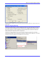
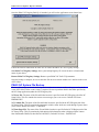
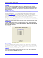
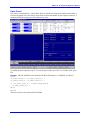
PMAC-NC Pro2 Software Reference Manual Decode Control = Turbo PMAC I7mn0 parameter value. Default is 4. Encoder Lines = The number of lines specified by the Encoder manufacturer used for the feedback. Example: For standard 5mm-pitch ballscrew and 8192 lines encoders, the pulses per unit value is: Pulses Per Unit = 4 cts/Line * 8192 lines/rev * rev/5mm *25.4 mm/inch = 166461.48 pulses per inch. Where 4 cts /line is decode control I7mn0 variable of PMAC Position Units This allows defining the position unit of the machine in either inches or meters (inch/mm). This setting is for the complete machine, not for individual motors. The first time the program is started, this value defaults to English (Inch), and English (Inch) is checked on the window. Select Metric (mm) and the program will start in Metric (mm) thereafter until switched back to English. Reset All Click this button to set all definitions to 0 (zero). As zero indicates that the axis is not connected, this function sets a new axis motor definition quickly. Display Format This allows defining the display format for different position units. This display format is used by PMAC-NC Pro2 to display the axis position. The convention of the format is ##.###; (i.e. total number of digits is five, with three of them after the decimal point). Default format is 9.4 which mean total width is nine digits with four digits after the decimal point. 20 Autopilot Utility PMAC-NC Pro2 Software Reference Manual The Second step is to configure the NC PLC settings. Select the Std PLC tab. Std PLC Function Use the Std PLC function to configure, create, and download PLCs to PMAC and start the basic function of the NC. The basic functionality includes: Mode selection Axis selection Jog Speed selection Hand wheel operation All function keys from the Control panel (single step, optional stop, block del, etc.) Machine Name Enter a machine name up to 15 characters in the Machine Name field. This name is used for generating the .CFG file as well as for creating the directory. The default machine name is Adv 600, which is one of Delta Tau’s available control panels. For example, if the machine is MyMachine, then CNCAutoPilot will create the directory MyMachine under c:\Program Files\Delta Tau\. All of the PLCs, headers, etc. files are stored in this folder. Autopilot Utility 21 PMAC-NC Pro2 Software Reference Manual PLC Path The PLC Path field indicates where the PLC files are stored. The standard base path C:\Program Files\Delta Tau . The \<Machine Name> will be appended to base path to create folder for storing PLCs. The Browse button is used to set PLC base path. As soon as a machine name is entered, the PLC path is updated automatically. Cntl Panel Function In this Cntl Panel group of fields, enter the values to create the Control Panel PLC. Delta Tau standard PMAC-NC Pro2 has different types of Control Panels. Currently this software supports Adv 600, Adv 810, Software Panel and ADV900. The details of these control panels are available at www.deltatau.com. The Control Panel PLC outputs changes according to the selection of the control panel. Select the appropriate panel. By default, Adv 600 control panel is selected. The Software Control Panel is selected when NC4.x will be running without a hardware control panel. The Control Panel PLCs support NC4.x software and more. These control panel PLCs will not work with older NC software such as NC2.36 or NC3.x. To support old NC software, use the Autopilot which comes with the installation of the old NC software. Adv. Settings If the Adv. Settings function is clicked, the window shown below displays. Advance Settings allows setting of some special features of NC. These settings are useful for ADV600 style control panel and ACC34 style PMAC I/O boards. Advance Settings No. of I/O Cards This box is for adding I/O cards. Default control panel PLC reads and writes one I/O card. When the control panel type is Adv 810, then these settings are not available. For Adv 810, use I/O M-Variables defined in the IO810.H file. The file can be found at C:\Program Files\Delta Tau Shared\IO810.h. This file is already included in the .CFG file output of Auto Pilot. Override Enter the values for the machine override parameters in this group of fields. ADV 810 and ADV900 control panels supports only ANALOG type overrides. 22 Autopilot Utility PMAC-NC Pro2 Software Reference Manual % Spindle Override Enter the values to set the Spindle Override percentages in this group of fields. The value in the % Speed Min field sets the minimum percentage spindle override and the value in the Speed Max field sets the maximum percentage spindle override. The Digital and Analog options set the type of switch used for setting spindle override. Range: Default 50 to 110 Allowed 0 to 200 (Settable) % Feedrate Override This group of fields is used to set the feedrate override percentages. The value in the % Feed Min field sets the minimum percentage feedrate override and the value in the % Feed Max field sets the maximum percentage feedrate override. The Digital and Analog options set the type of switch used for setting spindle override. To use analog pots for spindle override, click the Analog option. Range: Default 0 to 150 Allowed 0 to 200 (Settable) Home Enter the value for the Home PLC in this group of fields. When Command is selected, the #xHM commands are issued through the Control Panel PLC. If selected, this button resets the Enable option. When PLC is selected, the HOME commands are issued through the HOME PLC. This is set automatically if Enable is checked. Currently, Home using the motion program feature is disabled. Handle Enter the value for the Handle PLC in this group of fields. The value in the Max Handle field sets the limit for the maximum handwheel increment per one revolution. By default, this increment is one inch. The value in the Min field sets the minimum handwheel increment per division. Default settings are: Hand Wheel Revolution Speed Selection Position Increment 1 1 High (Max) Medium 1 Inch 0.1 Inch 1 Low (Min) 0.01 Inch In this group, Max is set to 0.01 by default. A typical pulse generator has 100 divisions. Thus in High setting, the motor will move 0.01 *100 = 1 Unit. Spindle Enter the value for the Spindle PLC in this group of fields. Type: This parameter allows selection of the spindle type as Close Loop or Open Loop. The Close Loop spindle requires a feedback; Open Loop does not. Max RPM: This parameter allows the definition of the maximum spindle speed. Spindle PLC uses this input to set the proper RPM. The program will not accept an RPM command greater than the value in the Max RPM field; it will clamp it to Max RPM. PMAC Type The program detects the type of the PMAC automatically and displays it here. Autopilot Utility 23 PMAC-NC Pro2 Software Reference Manual Enable PLC If Enable PLC is checked, then all of the generated PLCs are enabled by issuing Enable PLC command to PMAC after download. Save PLC If Save PLC is checked, then the SAVE command is issued to PMAC after download. This saves all of the PLCs and I-Variables in the PMAC memory. There are five standard PLCs that can be configured, based on the type of control panel hardware. The next section explains more about configuring these PLCs. Machine Setup Function Enter the values of all the basic machine-related settings for PMAC-NC Pro2, such as speed, following error, etc., in this group of fields. The menu window is self-explanatory. The axes are displayed only if they are assigned to the motor. In Window 28, only X, Y, Z, and S are displayed. Therefore, only X, Y, Z, and S are assigned to the motor as displayed on the Axis Motor window. Jog Speed This sets the maximum axis jog speed in user-selected units. The user-selected unit is displayed as machine unit. The speed setting can be different for different motors. 24 Autopilot Utility PMAC-NC Pro2 Software Reference Manual Rapid Speed This sets the maximum axis rapid speed in user-selected units. This setting can be different for different motors. This speed is G0 speed in NC terms. Positive S/W Limit This sets the positive software limit in user-selected units. This setting can be different for each motor. Negative S/W Limit This sets the negative software limit in user-selected units. This setting can be different for each motor. Home Offset This sets the distance in user-selected units to move after machine completes the HOME PLC. Home Speed This sets the maximum machine home speed in user-selected units. This setting can be different for each motor. Speed can be positive or negative. Positive Limit Switch Negative Limit Switch Home Switch Home on C Channel This group of buttons per axis sets the basic condition for homing. For example, if Positive Limit Switch is selected, then homing will be done on the rising edge of the positive limit switch and the rising edge of C channel. This is the same for the other two switches. Home on C Channel is used if the homing is to be done on the rising edge of C channel only. Only one type of condition is selected (Rising Edge). CS Setup This group of fields contains the settings related to the NC coordinate system. Feed Rate This sets the maximum axis feed rate in user-selected units. This setting is for a complete machine and not for individual axes. This speed is G1, G2, G3 speed, in NC terms . Following Error This sets the maximum following error in user-selected units. This setting is for a complete machine and not for individual axes. In Position Band This sets the In Position band in user-selected units. This setting is for a complete machine and not for individual axes. LookAhead ON This option is checked if the PMAC type is a Turbo. This sets the basic starting parameters for the look ahead mode for the NC. These settings depend upon the PMAC CPU frequency. The following IVariables will be set for NC Coordinate System 1: I5113 = Move segmentation time I5187 = Acceleration time I5120 = Number of segment For details on these parameters, refer to the PMAC Turbo User Manual. Functions There are three functions available on all windows. Update This option updates the Windows registry values used by PMAC-NC Pro2. Registry values must be updated after the configuration of axes is complete for PMAC-NC Pro2 to reflect the NC setup Autopilot Utility 25 PMAC-NC Pro2 Software Reference Manual configuration. Update will work only if the PMAC-NC PRO2 application is not running. In addition, registry values will not be updated if the key is not active; an error will be displayed. Build When selected, this function generates the PLCs that are marked enable. All the PLCs are stored in selected <PLC PATH>. The next step is to download these PLCs manually, using PEWIN Executive software. Use the <Machine Name>.CFG file for the download. Build and Download This function generates the PLCs that are marked enable. All the PLCs are stored in selected <PLC PATH>. This downloads the machine name .CFG file to PMAC automatically. If selecting ENABLE PLC and SAVE PLC, it issues the appropriate commands to PMAC. NCUI Registry Functions The last step is to set Default NCUI file path. 26 Autopilot Utility PMAC-NC Pro2 Software Reference Manual File Management NC Program to Load This stores the NC file with path to be loaded in NCUI interface on start-up of the application. NC Program Folder This sets default NC file path. NC will use this path as default to open different machine files.(.NC) NC Error File This sets the path for storing Errors data file. NC will use this file to show different users error. NC Variable File This sets the path for storing Parametric variable in data file. NC PagesDatFile This sets the path for loading Pages.Dat file to be used in NC diagnostic menu. NC Buffers The NC Buffers section of the AutoPilot utility configures the parameters which control the way PMACNC Pro2 utilizes Turbo PMAC’s advanced lookahead features. LookAhead Buffer This parameter determines the number of move segments that can be stored in PMAC’s lookahead buffer (size in move segments). Synchronous M Buffer This parameter determines the number of synchronous M-variable assignments that can be stored in PMAC’s lookahead buffer. Rotary Buffer The rotary buffer parameter defines PMAC’s rotary buffer size for coordinate system 1. The Coordinate System Lookahead Length (Isx20) is configured via the Lookahead Buffer parameter. The AutoPilot utility places this value in the NC_I_VAR.IVR file (15120 = Lookahead Buffer Value). PMAC’s Lookahead and Rotary buffers are defined by the PMAC-NC Pro2 GUI on startup of the application. Each time the PMAC-NC Pro2 application is started, it issues the following two commands for coordinate system 1: DEFINE LOOKAHEAD {Lookahead Buffer Value}, {Synchronous M Buffer Value} DEFINE ROTARY {Rotary Buffer Value} For details regarding these settings, see the following sections in the Turbo PMAC Software Reference Manual: Coordinate System x Lookahead Length DEFINE LOOKAHEAD DEFINE ROTARY The next section will walk you through an AutoPilot example program to generate standard PLCs for a MILL machine. Autopilot Utility 27 PMAC-NC Pro2 Software Reference Manual Miscellaneous User Position Reporting If this check box is selected, then Autopilot will generate the default Position Reporting PLC. Users can alter this PLC and write their own calculation for position display. This is useful for displaying position when inverse kinematics is used with NC or position display for non conventional feedback devices. The feature will only work for Turbo PMAC Firmware V1.942 and above. WirelessPendentOn If this check box is selected, then Autopilot will update the NCUI registry which will allow to use WIRELESS PENDENT with ADV900 Control panel. Velocity Scale X, Velocity Scale Y, Velocity Scale Z These values are used as scale factor in Feed Rate calculation. HMI NC uses these values to display Feed Rate. Typically used when Dual feedback is used on machine. Default is 1. Tool This will allow user to configure Tool page columns in the NCUI like Geometry, Wear etc. The Maximum number of tools is 99.Any tool number entry more than 99 tools will reset back to default 50 tools. 28 Autopilot Utility PMAC-NC Pro2 Software Reference Manual CNC AutoPilot- Example This section will give a description of the CNC AutoPilot Program. Refer to the different screen pictures which show the input for generating the standard PLC for Adv 900 CNC control. On completion of these steps, the Build or Build & Download options can be clicked. If Build & Download is selected, make sure to check the ENABLE PLC and SAVE PLC option. Step 1: Run NC_Setup.EXE and select MILL option. Step 2: Set the Axis- Motor definition as shown in Fig.1 Step 3: Set machine Name for this example set it as MyMachine. See (Fig 2). Select ADV900 as control panel. Step 4: Set all the machine parameter like Jog Speed, Homing condition, following error etc. (See Fig 3) Step 5: Set the NC default File path and Buffer sizes. Step 6: Check ENABLE PLC and SAVE PLC check boxes and click Build & Download. This will generate the PLC and download it to PMAC. The PLCs are generated in a folder specified by PLC Path in Std PLC menu. A detailed explanation of these settings follows each of the following screenshots. Autopilot Utility 29 PMAC-NC Pro2 Software Reference Manual Setting Explanation for Std. PLC The ADV900 type control panel is selected. Control Panel, Override, Handle and spindle close loop PLC are selected. PMAC Type is UMAC. Home command is issued from Control panel PLC. Override controls are type Analog. Initialize PLC is not selected so all the initialize part is done in Control panel plc. User can generate the initialize PLC and add machine specific initialization. This PLC runs one time and disables itself. 30 Autopilot Utility PMAC-NC Pro2 Software Reference Manual Setting Explanation for Machine Setup The maximum Feed Rate, Following Error, and In Position band settings are coordinate system-specific and are in USER UNITS. In the above example, it is Inch specified by Machine Unit. Lookahead mode is ON. Homing is based on HOME Switch. Radio Button is selected for this option. All motor specific (Mtr#1, Mtr#2) settings are in User units, INCH. In our Axis- Motor definition, we have 4 motors assigned to X, Y, Z and spindle so only 4 motors settings are enabled on Machine Setup page. PMAC-NC Pro2 Customizable Features 31 PMAC-NC Pro2 Software Reference Manual Setting Explanation for NCUI Registry Under File management, all the default NC file paths are set. As a good integration practice, create a folder called CNC_programs on the hard drive. Use this folder to store all the NC specific files. In the above example, this folder has been created so that all the default path settings and default files will be stored here. NC Buffers setting specifies the PMAC buffer sizes. In our example, the lookahead buffer will be defined as follows: Def Look 400,100 And rotary buffer will be defined as... Def Rot 4000 32 PMAC-NC Pro2 Customizable Features PMAC-NC Pro2 Software Reference Manual For this example, assume that Build is clicked. This creates the PLC. The following screenshot shows the files generated by the CNC AutoPilot program. The Auto Pilot program creates the MyMachine folder and stores all of the PLCs in this folder. *.PLC — PMAC PLC files to be used with Adv 900 control panel *.H — Header files to be used in download Mill.* — Machine GMT code files (Mill.G, Mill.M and Mill.T) *.IVR — PMAC I variable file *.CFG — Configuration file to be used in downloading the PLC manually by using Pewin 32 software Updates and modifies a project workspace file. This will create MyMachine as a project in PEWIN32 PRO. To download, use MyMachine.CFG file from PEWIN32 Executive software. MyMachine.Log will be created as output file after download to check the errors. PMAC-NC Pro2 Customizable Features 33 PMAC-NC Pro2 Software Reference Manual MyMachine.CFG This file is the template file created by AutoPilot to be used in case of manual download. This file can be used in the future for further downloads. The sample file is displayed below File names can be added, deleted in the #include files field for additional PLCs (e.g., Lube, Coolant, etc.) and this file can be downloaded manually using the PEWIN utility. As a good integration practice, always use this file to download the PLC to PMAC. Add additional PLC files to this file. AutoPilot Files MyMachine_UserDefins.H This file is a blank file created by the AutoPilot program. The machine related #defines (Macros) can be written in this file for better document control and maintainability. As a good integration practice do not alter or modify Address.h or OEM.h etc files. Use this file to add machine specific stuff. NC_I_VAR.IVR This file stores all the I-Variables generated by AutoPilot program using the Machine Setup input. 34 PMAC-NC Pro2 Customizable Features PMAC-NC Pro2 Software Reference Manual INITIALIZE.PLC This is a one-time execution PLC. This is used to initialize the NC system variables or I/O. Additional variables can be placed in this file. CNTLPANEL.PLC This is the control panel PLC for Adv 810. OVERRIDE.PLC This is the percentage override control PLC used for spindle and feed rate. HOME.PLC This is the home PLC for all axes. HANDLE.PLC This PLC is for handle. SPINDLE.PLC This PLC is for spindle. It can be open or closed. Reset.PLC This is template PLC for Reset action. User can add RESET sequence or any other Reset related action in this PLC. GPTimer.PLC This PLC provides additional Timers. This PLC uses PMAC free memory location to create additional TIMERS. POSITION_REPORT.PLC This is user position reporting PLC generated only if the User Position Reporting check box is selected from miscellaneous group box. In our example we did not selected this check box so this PLC will not be generated. OEM.H This header file is created by the AutoPilot program based on user input and should not be altered. The MyMachine.H file is for general use. NCPLC.H The AutoPilot program generates this file. It consist of the #defines constant based on the user input. MILL.G, MILL.M, and MILL.T are the G, M, and T code files used in the application. ADVCNTLU.H This file is in C:\Program Files\Common Files\Delta Tau Shared folder and should not be altered. This will be useful in assigning user buttons on the Adv 810 control panel. IO810.H or IO600.H This file is an input output file. The IO810 header file is for the Adv 810 and IO600 is for an Adv 600 type controller. These files can be modified as needed and are found in C:\Program Files\Delta Tau\PmacNC\Mill. PMAC-NC Pro2 Customizable Features 35 PMAC-NC Pro2 Software Reference Manual MyMachine Project Workspace The NC Setup updates the default >INI file used by PEWIN32 pro and creates MyMachie as a project. This is very useful feature for controlling integrated Machine Source code. In this screen, the PEWIN32 PRO executive software shows MyMachine as a project with all the files built by AutoPilot. 36 PMAC-NC Pro2 Customizable Features PMAC-NC Pro2 Software Reference Manual These are the P, Q and M variable Resources used by the CNC Program: P Variable used M variable Used Q variable Used. P37 to P44 – ADDRESS.H M0 to M599 – ADDRESS.H P50 to P35 – ADVCNTLU.H M601 to M671- OEM.H P260 to P263 – OEM.H Reserved Q91 to Q99 for Turbo PMAC V 1.942 and above. command Q25 to Q140 – OEM.H M800 to M807-ADV900.H P291 to P297– OEM.H M2000 to M2010- ADV900.h Q200 to Q326 – ADDRESS.H P300 to P380– OEM.H P440 to P468– OEM.H P485 to P491 – ADVCNTL.H P500 to P502 – ADVCNTL.H P800 to P809 - ADV900.H P960 to P985– OEM.H PMAC-NC Pro2 Customizable Features 37 PMAC-NC Pro2 Software Reference Manual PMAC-NC PRO2 CUSTOMIZABLE FEATURES Turbo PMAC Lookahead Function Introduction Turbo PMAC can perform highly sophisticated lookahead calculations on programmed trajectories to ensure that the trajectories do not violate specified maximum quantities for the axes involved in the moves. This permits the writing of the motion program simply by describing the commanded path. Vector feedrate becomes a constraint instead of a command; programmed acceleration times are used only to define corner sizes and minimum move block times. Turbo PMAC will control the speed along the path automatically (but without changing the path) to ensure that axis limits are not violated. Lookahead calculations are appropriate for any execution of a programmed path where throughput has been limited by the need to keep execution slow throughout the path because of the inability to anticipate the few sections where slow execution is required. The lookahead function’s ability to anticipate these problem areas permits much faster execution through most of the path, dramatically increasing throughput. Because of the nature of the lookahead calculations – trajectory calculations are done well in advance of the actual move execution, and moves are kept within machine limits by the automatic adjustment of move speeds and times – they are not appropriate for some applications. Any application requiring quick reaction to external conditions should not use lookahead. In addition, any application requiring precise synchronization to external motion, such as those using PMAC’s external time base feature should not use lookahead. When the lookahead function is enabled, Turbo PMAC will scan ahead in the programmed trajectories, looking for potential violations of its position, velocity, and acceleration limits. If it sees a violation, it will then work backward through the pre-computed buffered trajectories, slowing down the parts of these trajectories necessary to keep the moves within limits. The calculations are completed before these sections of the trajectory are actually executed. Turbo PMAC can perform these lookahead calculations on LINEAR and CIRCLE mode moves. The coordinate system must be put in segmentation mode (Isx13 > 0) to enable lookahead calculations, even if only LINEAR mode moves are used. (The coordinate system must be in segmentation mode anyway to execute CIRCLE mode moves or cutter radius compensation.) In segmentation mode, Turbo PMAC splits the moves into small segments automatically, which are executed as a series of smooth splines to recreate the programmed moves. Turbo PMAC stores data on these segments in a specially defined lookahead buffer for the coordinate system. Each segment takes Isx13 milliseconds when it is put into the buffer, but this time can be extended if it or some other segment in the buffer violates a velocity or acceleration limit. This technique permits Turbo PMAC to create deceleration slopes in the middle of programmed moves, at the boundaries of programmed move, or over multiple programmed moves, whichever is required to create the fastest possible move that does not violate constraints. All of this is done automatically and invisibly inside the Turbo PMAC; the programmer and operator do not need to understand the workings of the algorithm. If Turbo PMAC’s inverse kinematic calculations are used, the conversion from tip coordinates to joint coordinates takes place before lookahead calculations, segment by segment for LINEAR and CIRCLE mode moves. Therefore, Turbo PMAC can execute the lookahead calculations in joint space, motor by motor, even if the system has been programmed in tip coordinates. Once the lookahead function has been set up, the lookahead function operates transparently to the programmer and the operator. No changes need to be made to a motion program to use the lookahead function, although the programmer may choose to make some changes to take advantage of the increased performance capabilities that lookahead provides. 38 PMAC-NC Pro2 Customizable Features PMAC-NC Pro2 Software Reference Manual Quick Instructions: Setting Up Lookahead The following list quickly explains the steps required for setting up and using the lookahead function on the Turbo PMAC. Greater detail and context are given in the subsequent section. 1. Assign all desired motors to the coordinate system with axis definition statements. 2. Set Ixx13 and Ixx14 positive and negative position limits, plus Ixx41 desired position-limit band, in counts for each motor in the coordinate system. Set bit 15 of Ixx24 to 1 to enable desired position limits. 3. Set Ixx16 maximum velocity in counts/msec for each motor in the coordinate system. 4. Set Ixx17 maximum acceleration in counts/msec2 for each motor in the coordinate system. 5. Set Isx13 segmentation time in msec for the coordinate system to minimum programmed move block time or 10 msec, whichever is less. 6. Compute maximum stopping time for each motor as Ixx16/Ixx17. 7. Select motor with longest stopping time. 8. Compute number of segments needed to look ahead as this stopping time divided by (2 * Isx13). 9. Multiply the segments needed by 4/3 (round up if necessary) and set the Isx20 lookahead length parameter to this value. 10. If the application involves high block rates, set the Isx87 default acceleration time to the minimum block time in msec; set the Isx88 default S-curve time to 0. 11. If the application does not involve high block rates, set the Isx87 default acceleration time and the Isx88 default S-curve time parameters to values that give the desired blending corner size and shape at the programmed speeds. 12. Store these parameters to non-volatile memory with the SAVE command to make them an automatic part of the machine state. 13. After each power-up/reset, send the card a DEFINE LOOKAHEAD {# of segments},{# of outputs} command for the coordinate system, where {# of segments} is equal to Isx20 plus any segments for which backup capability is desired, and {# of outputs} is at least equal to the number of synchronous M-variable assignments that may need to be buffered over the lookahead length. 14. Load the motion program into the Turbo PMAC. The motion program defines the path to be followed. The lookahead algorithm may reduce the speed along the path, but it will not change the path. 15. Run the motion program, and let the lookahead algorithm do its work. Detailed Instructions: Setting up Lookahead A few steps are required to calculate and set up the lookahead function. Typically, the calculations only have to be done once in the initial configuration of the machine. Once configured, the lookahead function operates automatically and invisibly. Defining the Coordinate System The lookahead function checks the programmed moves against all motors in the coordinate system. The first step is therefore to define the coordinate system by assigning motors to axes in the coordinate system with axis definition statements. This action is covered in the Setting up the Coordinate System section of the User Guide. Lookahead Constraints Turbo PMAC’s lookahead algorithm forces the coordinate system to observe four constraints for each motor. These constraints are defined in I-variables for each motor representing maximum position PMAC-NC Pro2 Customizable Features 39 PMAC-NC Pro2 Software Reference Manual extents, velocities, and accelerations. These I-variables must be set up properly in order for the lookahead algorithm to work properly. Position Limits Variables Ixx13 and Ixx14 for each Motor xx define the maximum positive and negative position values, respectively, that are permitted for the motor (software overtravel limits). These variables are defined in counts, and are referenced to the motor zero, or home, position (often called machine zero). Even if the origin of the axis for programming purposes has been offset (often called program zero), the physical position of these position limits does not change; they maintain their reference to the machine zero point. Turbo PMAC checks the actual position for each motor as the trajectory is being executed against these limits; if a limit is exceeded, the program is aborted and the motors are decelerated at the rate set by Ixx15. Variable Ixx41 for each Motor xx defines the distance between the actual position limits explained above, and the desired position limit that can be checked at move calculation time, even in lookahead. That is, if the calculated desired move position is greater than (Ixx13 – Ixx41), or less than (Ixx14 + Ixx41), this will constitute a desired position limit violation. Desired position limits are only checked if bit 15 of Ixx24 is set to 1. In this mode, if the lookahead algorithm, while scanning ahead in the programmed trajectory, determines that any motor in the coordinate system would exceed one of its desired position limits, it will suspend the program and force a stop right at that limit. It will then work backwards through the buffered trajectory segments to bring the motors to a stop along the path at that point in the minimum time that does not violate any motor’s Ixx17 acceleration constraint. Note: If bit 14 of Ixx24 is also set to 1, the program does not stop at the limit. Instead, it will continue, with the offending motor saturating at the limit value. When stopped on a desired position limit within lookahead, the program is only suspended, not aborted. The action is effectively equivalent to issuing a \ quick-stop command. It is possible to retrace the path coming into the limit, or even to resume forward execution after changing the limit value. An abort command must be issued before another program can be started. Note: If an actual position limit is also tripped during the deceleration to a stop at the desired position limit, the program is aborted, so retracing and resuming are not possible. For this reason, if the possibility of retracing and resuming is important, Ixx41 should be set to a large enough value so that the actual position limit is never tripped during a desired position limit stop. This technique permits these software position limits to be placed just within the hard stops of the machine. Without the desired position limits, the software position limits cannot be detected until the actual trajectory passes the limit. This requires that these limits be placed far enough within the hard stops so that the motors have enough distance to stop after they pass the limits. (When a motor hits a software position limit without lookahead, the deceleration of motors is controlled by Ixx15, not Ixx17, and deceleration is not necessarily along the programmed path.) 40 PMAC-NC Pro2 Customizable Features PMAC-NC Pro2 Software Reference Manual Velocity Limits Variable Ixx16 for each Motor xx defines the magnitude of the maximum velocity permitted for the motor. These variables are defined in the raw PMAC units of counts per millisecond, so a quick conversion must be calculated from the user units (e.g. millimeters per minute). If the algorithm, while looking ahead in the programmed trajectory, determines that any motor in the coordinate system is being asked to violate its velocity limit, it will slow down the trajectory at that point just enough so that no limit is violated. It will then work backwards through the buffered trajectory segments to create a controlled deceleration along the path to this limited speed in the minimum time that does not violate any motor’s Ixx17 acceleration constraint. Note: During the initial move-block calculations, before move data is sent to the lookahead function, a couple of factors can result in commanded velocities lower than what is programmed. First, if the vector feedrate commanded in the motion program with the F command exceeds the maximum feedrate parameter Isx85, then Isx85 is used instead. Second, if the move-block time, either specified directly with the TM command, or calculated as vector-distance divided by vectorfeedrate, is less than the programmed acceleration time (the larger of TA or 2 * TS), the programmed acceleration time is used instead. This results in a speed less than what was programmed. The lookahead function can further slow these moves, but it cannot speed them up. Acceleration Limits Variable Ixx17 for each Motor xx defines the magnitude of the maximum acceleration permitted for the motor. These variables are defined in the raw PMAC units of counts per (millisecond-squared), so a quick conversion must be calculated from the user units (e.g. in/sec 2, or g’s). If the algorithm, while looking ahead in the programmed trajectory, determines that any motor in the coordinate system is being asked to violate its acceleration limit, it will slow down the trajectory at that point just enough so that no limit is violated. It will then work backwards through the buffered trajectory segments to create a controlled deceleration along the path to this limited speed in the minimum time that does not violate any motor’s Ixx17 acceleration constraint. Calculating the Segmentation Time Turbo PMAC’s lookahead function operates on intermediate motion segments calculated from the programmed trajectory. An intermediate point for each motor is computed once per segment from the programmed path, and then a fine interpolation using a cubic spline to join these segments is executed at the servo update rate. The user settable segmentation time is therefore an important parameter for optimization of the lookahead function. Variable Isx13 for each Coordinate System ‘x’ defines the time for each intermediate segment in the programmed trajectory, in milliseconds, before it is possibly extended by the lookahead function. Isx13 is an integer value; if a non-integer value is sent, Turbo PMAC will round to the next integer. If Isx13 is set to 0, the coordinate system is not in segmentation mode; no intermediate segments are calculated, and the lookahead function cannot be enabled. Several issues must be addressed in setting the Isx13 segmentation time. These include its relationship to the maximum block rate, the small interpolation errors it introduces, and its effect on the calculation load of the Turbo PMAC. Each of these is addressed in the following sections. PMAC-NC Pro2 Customizable Features 41 PMAC-NC Pro2 Software Reference Manual Block Rate Relationship In most applications, the Isx13 segmentation time will be set so that it is less than or equal to the minimum block (programmed move) time. Put another way, the segmentation rate defined by Isx13 is usually set greater than or equal to the maximum block rate. For example, if a maximum block rate of 500 blocks per second is desired, the minimum block time is 2 milliseconds, and Isx13 is set to a value no greater than 2. This relationship holds because blocks of a smaller time than the segmentation time are skipped over as Turbo PMAC looks for the next segment point. While this does not cause any errors, there is no real point in putting these programmed points in the motion program if the controller is going to skip over them. However, some inherit old motion programs with points closer together than is actually required; these users may have reason to set the segmentation time larger than the minimum block time. Note: The programmed acceleration time sets a limit on the maximum block rate. The move time for a programmed block, even before lookahead, is not permitted to be less than the programmed acceleration time. The programmed acceleration time is the larger of the TA time (TA = Isx87 by default) and twice the TS time (TS = Isx88 by default). In high-block-rate lookahead applications, the TA time is typically set equal to the minimum desired block time, and typically the TS time is set to (because it squares up corners). Calculation Implications While smaller Isx13 segmentation times permit higher real maximum block rates and permit more accurate interpolation, they increase the Turbo PMAC computational requirements, particularly when lookahead is active. The following table shows the result of benchmarking tests on the Turbo PMAC and the minimum segmentation times that can be used for a given number of axes executing lookahead calculations. Number of Axes Maximum Block Rate (blocks/sec) Minimum Segmentation Time (msec) 2 3 4 5 6 8 12 16 2000 1000 500 500 500 333 250 200 1 @ 200% 1 2 2 2 3 4 5 Notes: 1. Tests performed on 80 MHz Turbo PMAC. 2. Tests performed at default 2.25 kHz servo update rate. 3. Tests performed with no PMAC motor commutation or current-loop closure. 4. Higher block rates can be done, but segmentation will smooth out features. Note: Subject to these constraints, the length of the lookahead is subject only to memory limitations in the Turbo PMAC. In general, the Isx13 segmentation time is set to the largest value that meets user requirements in each of the above three concerns. However, it is seldom set larger than 10 msec. Calculating the Required Lookahead Length 42 PMAC-NC Pro2 Customizable Features PMAC-NC Pro2 Software Reference Manual In order for the coordinate system to reach maximum performance, it must be looking ahead for the time and distance required for each motor to come to a full stop from maximum speed. Because the lookahead buffer stores motion segments, this lookahead length must be expressed in segments. To calculate this value, first compute the worst-case time required to stop for each motor in the coordinate system. This value can be obtained by dividing the maximum motor velocity by the maximum motor acceleration. In terms of Turbo PMAC parameters: StopTime( m sec) Ixx16 Ixx17 Now take the motor with the longest stop time, and divide this time by 2 (because the segments will come in at maximum speed, which takes half the time of ramping down to zero speed). Next, convert this value to a number of segments by dividing by the coordinate system segmentation time: StopTime( m sec) LookaheadLength( segs ) 2 * Isx13( m sec s / seg ) Ixx16 2 * Ixx17 * Isx13 This is the number of segments in the lookahead buffer that must be always properly computed ahead of time. Because the Turbo PMAC does not recalculate fully the lookahead buffer every segment, actually it must look further ahead than this number of required segments Lookahead Length Parameter Variable Isx20 for the coordinate system tells the algorithm how many segments ahead in the program to look. This value is a function of the number of segments that must always be correct in the lookahead buffer (SegmentsNeeded). The formula is: Isx20 4 * SegmentsNeeded 3 Setting Isx20 to a value larger than needed does not increase the computational load (although it does increase the time of heaviest computational load while the buffer is filling). However, it does require more memory storage, and it does increase the delay in having the program react to any external conditions. Setting Isx20 to a value smaller than needed does not cause the limits to be violated. However, it may cause Turbo PMAC to limit speeds more severely than the Ixx16 limits require in order to ensure that acceleration limits are not violated. In addition, a saw-tooth velocity profile may be observed. Note: Preliminary versions of the Turbo PMAC firmware had three additional parameters controlling the dynamics of the lookahead operation: Isx21, Isx22, and Isx23. In the current versions of the firmware, these values are fixed at 3, 6, and 7, respectively, and the variables have been removed. Isx21 now permits direct control of the lookahead state of operation. Defining the Lookahead Buffer In order to use the lookahead function in a Turbo PMAC coordinate system, a lookahead buffer must be defined for that coordinate system, reserving memory for the buffer. This is done with the on-line coordinate-system-specific DEFINE LOOKAHEAD command. Because lookahead buffers are not retained through a power down or reset, this command must be issued after every power-up or board reset. There are two values associated with the DEFINE LOOKAHEAD command. The first determines the number of motion segments for each motor in the coordinate system that can be stored in the lookahead buffer. At a minimum, this must be set equal to Isx20. PMAC-NC Pro2 Customizable Features 43 PMAC-NC Pro2 Software Reference Manual If this value is set greater than Isx20, the lookahead buffer stores historical data. This data can be used to reverse through the already executed trajectory. If reversal is desired, the buffer should be sized to store enough back segments to cover the desired backup distance. There is no penalty for reserving more memory for these synchronous M-variable assignments than is needed, other than the loss of this memory for other uses. The room reserved for the segment data in the lookahead buffer is dependent on the number of motors assigned to the coordinate system at the time of the DEFINE LOOKAHEAD command. If the number of motors assigned to the coordinate system then changes, the organization of the lookahead buffer will be wrong, and the program will abort with a run-time error on the next move after the coordinate system is changed. If the coordinate system must be changed during an application that uses lookahead, the lookahead buffer must first be deleted, then defined again after the change. The following motion program code shows how this could be done: DWELL 10 CMD “&1 DELETE LOOKAHEAD” CMD “&1 #4->100C” CMD “&1 DEFINE LOOKAHEAD 1000,100” DWELL 10 ; ; ; ; ; Stop lookahead execution Delete buffer Assign new motor to C. S. 1 Redefine buffer Make sure commands execute The second value associated with the DEFINE LOOKAHEAD command determines the number of synchronous M-variable assignments (e.g. M1==1) for the coordinate system that can be stored in the lookahead buffer. Synchronous M-variable assignments in the motion program delay the actual assignment of the value to the M-variable until the start of actual execution of the next move in the motion program. Therefore, these actions must be held in a buffer pending execution. This size of the buffer for these assignments must be at least as great as the largest number of assignments expected during the time for lookahead. There is no penalty for reserving more memory for these synchronous M-variable assignments than is needed, other than the loss of this memory for other uses. Note: The buffer reserved in this manner for synchronous M-variables under lookahead is distinct from the fixed-size buffer used for synchronous M-variables without lookahead. For example, the command &1 DEFINE LOOKAHEAD 500,50 creates a lookahead buffer for Coordinate System 1 that can store 500 segments for each motor assigned to the coordinate system at that time, plus 50 synchronous M-variable assignments. 44 PMAC-NC Pro2 Customizable Features PMAC-NC Pro2 Software Reference Manual CUTTER RADIUS COMPENSATION Turbo PMAC provides the capability for performing cutter (tool) radius compensation on the moves it performs. This compensation can be performed among the X, Y, and Z axes, which should be physically perpendicular to each other. The compensation offsets the described path of motion perpendicular to the path by a programmed amount automatically, compensating for the size of the tool. This permits the user to program the path along the edge of the tool, letting Turbo PMAC calculate the tool-center path, based on a radius magnitude that can be specified independently of the program. Cutter radius compensation is valid only in LINEAR and CIRCLE move modes. The moves must be specified by F (feedrate), not TM (move time). Turbo PMAC must be in move segmentation mode (Isx13 > 0) to do this compensation (Isx13 > 0 is required for CIRCLE mode anyway.) Note: In CIRCLE mode, a move specification without any center specification results in a linear move. This move is executed correctly without cutter radius compensation active, but if the compensation is active, it will not be applied properly in this case. A linear move must be executed in LINEAR mode for proper cutter-radius compensation. Defining the Plane of Compensation Several parameters must be specified for the compensation. First, the plane in which the compensation is to be performed must be set using the buffered motion-program NORMAL command. Any plane in XYZspace may be specified. This is done by specifying a vector normal to that plane, with I, J, and Kcomponents parallel to the X, Y, and Z-axes, respectively. For example, NORMAL K-1, by describing a vector parallel to the Z-axis in the negative direction, specifies the XY-plane with the normal right/left sense of the compensation (NORMAL K1 would also use the XY-plane, but invert the right/left sense). This same command also specifies the plane for circular interpolation. NORMAL K-1 is the default. The compensation plane should not be changed while compensation is active. Other common settings are NORMAL J-1, which specifies the ZX-plane for compensation, and NORMAL I-1, which specifies the YZ-plane. These three settings of the normal vector correspond to RS-274 Gcodes G17, G18, and G19, respectively. If implementing G-codes in Turbo PMAC program 1000, incorporate them in PROG 1000: N17000 NORMAL K-1 RETURN N18000 NORMAL J-1 RETURN N19000 NORMAL I-1 RETURN Defining the Magnitude of Compensation The magnitude of the compensation – the cutter radius – must be set using the buffered motion program command CCR{data} (Cutter Compensation Radius). This command can take either a constant argument (e.g. CCR0.125) or an expression in parentheses (e.g. CCR(P10+0.0625)). The units of the argument are the user units of the X, Y, and Z-axes. In RS-274 style programs, these commands are often incorporated into tool data D-codes using Turbo PMAC motion program 1003. Negative and zero values for cutter radius are possible. Note that the behavior in changing between a positive and negative magnitude is different from changing the direction of compensation. See the Changes in Compensation section of this manual. In addition, the behavior in changing between a nonzero magnitude and a zero magnitude is different from turning the compensation on and off. See the appropriate sections of this manual. PMAC-NC Pro2 Customizable Features 45 PMAC-NC Pro2 Software Reference Manual Turning on Compensation The compensation is turned on by buffered motion program command CC1 (offset left) or CC2 (offset right). These are equivalent to the RS-274 G-Codes G41 and G42, respectively. If implementing G-Code subroutines in Turbo PMAC motion program 1000, simply incorporate them in PROG 1000: N41000 CC1 RETURN N42000 CC2 RETURN Turning off Compensation The compensation is turned off by buffered motion program command CC0, which is equivalent to the RS-274 G- Code G40. If implementing G-Code subroutines in Turbo PMAC motion program 1000, incorporate them in PROG 1000: N40000 CC0 RETURN How Turbo PMAC Introduces Compensation Turbo PMAC gradually introduces compensation over the next LINEAR or CIRCLE mode move following the CC1 or CC2 command that turns on compensation. This lead-in move ends at a point one cutter radius away from the intersection of the lead-in move and the first fully compensated move, with the line from the programmed point to this compensated endpoint being perpendicular to the path of the first fully compensated move at the intersection. Note: A few controllers can make their lead-in move a CIRCLE-mode move. This capability permits establishing contact with the cutting surface very gently, important for fine finishing cuts. Inside Corner Introduction If the lead-in move and the first fully compensated move form an inside corner, the lead-in move goes directly to this point. When the lead-in move is a LINEAR mode move, the compensated tool path will be at a diagonal to the programmed move path. When the lead-in move is a CIRCLE mode move, the compensated tool path will be a spiral. Introducing Compensation – Inside Corner Line Programmed Path r Line Tool Center Path Line Programmed Path r Arc Line Arc Line Line CC2 Tool Center Path CC2 Line to Line Line to Arc Line Programmed Path r Arc Tool Center Path Line Arc Spiral Spiral Arc Tool Center Path CC2 CC2 Arc to Line 46 Programmed Path r Arc Arc to Arc PMAC-NC Pro2 Customizable Features PMAC-NC Pro2 Software Reference Manual Outside Corner Introduction If the lead-in move and the first fully compensated move form an outside corner, the lead-in move first moves to a point one cutter radius away from the intersection of the lead-in move and the first fully compensated move, with the line from the programmed point to this compensated endpoint being perpendicular to the path of the lead-in move at the intersection. When the lead-in move is a LINEAR mode move, this compensated tool path will be at a diagonal to the programmed move path. When the lead-in move is a CIRCLE mode move, this compensated tool path will be a spiral. Then a circular arc move with radius equal to the cutter radius is added, ending at a point one cutter radius away from the intersection of the lead-in move and the first fully compensated move, with the line from the programmed point to this compensated endpoint being perpendicular to the path of the first fully compensated move at the intersection. Introducing Compensation – Outside Corner CC2 CC2 Line Line Line Programmed Path Line r r Programmed Path Arc Line Line to Line Tool Center Path r Tool Center Path Arc Arc r Line Line to Arc CC2 CC2 Arc Programmed Path Arc Line Programmed Path Spiral r Arc Spiral r Arc Arc r r Tool Center Path Line Tool Center Path Arc Arc to Line Arc to Arc Note: The behavior for lead-in moves is different from changing the compensation radius from zero to a non-zero value while compensation is active. An arc move is always added at the corner, regardless of the setting of Isx99. This ensures that the lead-in move never cuts into the first fully compensated move. Treatment of Inside Corners Inside corners are still subject to the blending due to the TA and TS times in force (default values set by coordinate system I-variables Isx87 and Isx88, respectively). The longer the acceleration time, the larger the rounding of the corner. (The corner rounding starts and ends a distance F*TA/2 from the compensated, but unblended corner.) The greater the portion of the blending is S-curve, the squarer the corner will be. When coming to a full stop (e.g. Step, Quit, or DWELL at the corner) at an inside corner, Turbo PMAC will stop at the compensated, but unblended, corner point. PMAC-NC Pro2 Customizable Features 47 PMAC-NC Pro2 Software Reference Manual Inside Corner Cutter Compensation Line Programmed Path r r Line Tool Center Path Line Programmed Path r Line Arc r Arc Line Line Tool Center Path Line to Line Line to Arc Line Programmed Path Programmed Path r r Arc Tool Center Path Line Arc r Arc Arc r Arc Arc Tool Center Path Arc to Line Arc to Arc Treatment of Outside Corners For outside corners, Turbo PMAC will either blend the incoming and outgoing moves directly together, or it will add an arc move to cover the additional distance around the corner. Which option it chooses is dependent on the relative angle of the two moves and the value of I-variable Isx99. The relative angle between the two moves is expressed as the change in directed angle of the motion vector in the plane of compensation. If the two moves are in exactly the same direction, the change in directed angle is 0o; if there is a right angle corner, the change is +/-90o; if there is a complete reversal, the change in directed angle is 180o. Isx99 specifies the boundary angle between directly blended outside corners and added-arc outside corners. It is expressed as the cosine of the change in the directed angle of motion (cos0 o=1.0, cos90o=0.0, cos180o=-1.0) at the boundary of the programmed moves. The change in directed angle is equal to 180 o minus the included angle at the corner. Sharp Outside Corner If the cosine of the change in directed angle is less than Isx99, which means the corner is sharper than the specified angle, then an arc move will be added around the outside of the corner. 48 PMAC-NC Pro2 Customizable Features PMAC-NC Pro2 Software Reference Manual Outside Corner Cutter Compensation, Sharp Angle (cos < Isx99) Line Arc Line Arc Line r Line r Programmed Path r Arc Tool Center Path Programmed Path r Arc Tool Center Path Line Line Line to Line Line Line to Arc Arc Line Arc r r Programmed Path Arc r Arc Programmed Path Arc r Arc Arc Arc Tool Center Path Tool Center Path Arc to Line Arc to Arc Outside Corner Cutter Compensation, Shallow Angle ( cos > Isx99) Line Programmed Path Line r Line Line Programmed Path r Line r r Arc Tool Center Path Line Tool Center Path Line to Line Line to Arc Arc Arc Arc Arc Line Programmed Path r r Tool Center Path Line Arc to Line Arc Programmed Path r Arc r Arc Tool Center Path Arc to Arc Shallow Outside Corner If the cosine of the change in directed angle is greater than Isx99, which means that the corner is flatter than the specified angle, the moves will be directly blended together without an added arc. The added arc prevents the compensated corner from extending too far out on the outside of a sharp corner. However, as an added move, it has the minimum time of the acceleration time, which can cause a slowdown on a very shallow angle. While the default value for Isx99 of 0.9998 (cos1 o) causes an arc to be added on any change in angle greater than 1o, many will set Isx99 to 0.707 (cos45o) or 0.0 (cos90o) so arcs are only added on sharp corners. When coming to a full stop (e.g. Step, Quit, /, or DWELL) at an outside corner with an added arc, Turbo PMAC will include the added arc move before stopping. When coming to a full stop at an outside corner without an added arc, Turbo PMAC will stop at the compensated, but unblended, corner point. PMAC-NC Pro2 Customizable Features 49 PMAC-NC Pro2 Software Reference Manual Treatment of Full Reversal If the change in directed angle at the boundary between two successive compensated moves is 180 o + 1o (the included angle is less than 1o), this is considered a full reversal and special rules apply. If both the incoming and outgoing moves are lines, the corner is always considered an outside corner, and an arc move of approximately 180o is added. If one or both of the moves is an arc, Turbo PMAC will check for possible inside intersection of the compensated moves. If such an intersection is found, the corner will be treated as an inside corner. Otherwise, it will be treated as an outside corner with an added 180 o arc move. Reversal In Cutter Compensation Line Programmed Path Line <1o Line Line Tool Cen ter Path r r Arc Arc Tool Center Arc Path Right r Tool Center Path Left Line to Arc, Inside and Outside Arc r Programmed Path r Arc Arc Arc Arc Arc Line r Line to Line Tool Center Path Programmed Path Line Arc r r Arc Arc Programmed Path Arc to Arc Outside Arc Tool Center Path Arc Arc to Arc Inside Note on Full Circles If a full-circle move is executed while in cutter compensation and one or both of the ends produces a shallow outside corner that is directly blended (no added arc – see the previous section, Treatment of Outside Corners.), the compensated arc move will be extended beyond 360o. In addition, Turbo PMAC may produce just a very short arc, 360o shorter than what is desired (making it appear that the circle has been skipped. Typically, while this is the result of sloppy programming – an outside corner with a full circle causes an overcut into the circle – many machine designers may want to permit slight cases of this. Coordinate system parameter Isx97 defines the shortest arc angle that may be executed; the longest arc angle is 360 o plus this angle. The default value of Isx97 sets a minimum arc angle of one-millionth of a semi-circle, enough to account for numerical round off, but sometimes not enough for compensated full circles. To handle these cases, Isx97 should be set to a somewhat larger value. 50 PMAC-NC Pro2 Customizable Features PMAC-NC Pro2 Software Reference Manual Failure When Compensation Extends Full Circle Tool Center Path 1 1 r r 2 Programmed Path r Short Arc Executed Compensated Circle “Skipped” 3 2 Programmed Full Circle Speed of Compensated Moves Tool center speed for the compensated path remains the same as that programmed by the F parameter. On an arc move, this means that the tool edge speed (the part of the tool in contact with the part) will be different from that programmed by the fraction Rtool/Rarc. Changes in Compensation Radius Magnitude Changes Changes in the magnitude of compensation (new CCR values) made while compensation is active are introduced linearly over the next move. When this change is introduced over the course of a LINEAR mode move, the compensated tool path will be at a diagonal to the programmed move path. When this change is introduced over the course of a CIRCLE mode move, the compensated tool path will be a spiral. Compensation Direction Changes Changes in the direction of compensation (between CC1 and CC2) made while compensation are generally introduced at the boundary between the two moves. However, if there is no intersection between the two compensated move paths, the change is introduced linearly over the next move. Cutter Compensation Change of Direction – No Intersection Programmed Path CC1 Line Line CC2 Line Line Line Programmed Path Line Line CC1 Line Tool Center Path Spiral CC2 Arc Line Tool Center Path Line Change Through a Line Change Through an Arc Tool Center Path Arc Arc CC1 Line Line CC2 Programmed Path Arc CC2 Programmed Path CC1 Line r Arc Tool Center Path Line Change Through a Line PMAC-NC Pro2 Customizable Features Change in Reversal 51 PMAC-NC Pro2 Software Reference Manual How Turbo PMAC Removes Compensation Turbo PMAC gradually removes compensation over the next LINEAR or CIRCLE mode move following the CC0 command that turns off compensation. This lead-out move starts at a point one cutter radius away from the intersection of the lead-in move and the first fully compensated move, with the line from the programmed point to this compensated endpoint being perpendicular to the path of the first fully compensated move at the intersection. Note: A few controllers can make their lead-out move a CIRCLE mode move. This capability permits releasing contact with the cutting surface very gently, important for fine finishing cuts. Inside Corner If the last fully compensated move and the lead-out move form an inside corner, the lead-out move starts directly from this point to the programmed endpoint. When the lead-out move is a LINEAR mode move, the compensated tool path will be at a diagonal to the programmed move path. When the lead-in move is a CIRCLE mode move, the compensated tool path will be a spiral. Removing Compensation – Inside Corner Line Programmed Path Tool Center Path Line CC0 CC0 Programmed Path r r Arc Line Line Arc Line Tool Center Path Line to Line Line Programmed Path Tool Center Path Line Line Line to Arc CC0 CC0 r Arc Programmed Path r Arc Arc Spiral Arc to Line Arc Tool Center Path Spiral Arc to Arc Outside Corner If the last fully compensated move and the lead-out move form an outside corner, the last fully compensated move ends at a point one cutter radius away from the intersection of the last fully compensated move and the lead-out move, with the line from the programmed point to this compensated point being perpendicular to the path of the fully compensated move at the intersection. Turbo PMAC then adds a circular arc move with radius equal to the cutter radius, ending at a point one cutter radius away from the same, with the line from the programmed point to this compensated endpoint being perpendicular to the path of the lead-out move at the intersection. Finally, Turbo PMAC gradually removes compensation over the lead-out move itself, ending at the programmed endpoint of the lead-out move. When the lead-out move is a LINEAR mode move, this compensated tool path will be at a diagonal to the programmed move path. When the lead-in move is a CIRCLE mode move, this compensated tool path will be a spiral. 52 PMAC-NC Pro2 Customizable Features PMAC-NC Pro2 Software Reference Manual Removing Compensation – Outside Corner Line Line Programmed Path Tool Center Path CC0 Line Arc r Line r Tool Center Path r Line Programmed Path CC0 Arc r Arc Line Line to Line Line to Arc Arc Line Programmed Path CC0 Spiral Arc r Tool Center Path r Tool Center Path Line Arc Programmed Path CC0 Arc Spiral r r Arc Arc Arc to Line Arc to Arc Note: This behavior is different from changing the magnitude of the compensation radius to zero while leaving compensation active. An arc move is always added at the corner, regardless of the setting of Isx99. This ensures that the lead-out move will never cut into the last fully compensated move. Failures in Cutter Compensation It is possible to give Turbo PMAC a program sequence in which the cutter compensation algorithm will fail not producing desired results. There are three reasons the compensation can fail: Inability to Calculate Through Corner First, if Turbo PMAC cannot see ahead far enough in the program to find the next move with a component in the plane of compensation before the present move is calculated, then it will not be able to compute the intersection point between the two moves. This can happen for several reasons: There is a move with no component in the plane of compensation (i.e., perpendicular to the plane of compensation, as in a Z-axis-only move during XY compensation) before the next move in the plane of compensation, and no CCBUFFER compensation block buffer declared. There are more moves with no component in the plane of compensation before the next move in the plane of compensation than the CCBUFFER compensation block buffer can hold. There are more than 10 DWELLs before the next move in the plane of compensation. Program logic causes a break in blending moves (e.g. looping twice through a WHILE loop). PMAC-NC Pro2 Customizable Features 53 PMAC-NC Pro2 Software Reference Manual Failures in Cutter Compensation Overcut Programmed Path Line r r r Tool Center Point at Failure Line Tool Center Point at Failure (No Overcut) Line Tool Center Path Arc r r Line Line Tool Center Path Programmed Path Line Line Line Failure to See Through Inside Corner Tool Center Path Line Arc Line r Line Line r Programmed Path Failure to See Through Outside Corner Line Programmed Path Arc r r Tool Center Path Line Stopping Point (Not Executed) Overcut Inside Corner Smaller Than Cutter Radius Line Arc Radius Smaller Than Cutter Radius If Turbo PMAC cannot find the next move in time, it will end the current move as if the intersection with the next move would form an outside corner. If the next move, when found, does create an outside corner, or continues straight on, compensation will be correct. On an outside corner, an arc move is always added at the corner, regardless of the setting of Isx99. However, if the next move creates an inside corner, the path will have overcut into the corner. In this case, Turbo PMAC will then move to the correct intersection position and continue with the next move, leaving the overcutting localized to the corner. Inside Corner Smaller than Radius Second, if the compensated path produces an inside corner with one of the moves shorter than the cutter radius, the cutter compensation will not work properly. This situation results in a compensated move that is in the opposite direction from that of the uncompensated move, and there will be overcutting at the corner. Inside Arc Radius Smaller than Cutter Radius Third, if the program requests an arc move with compensation to the inside, and the programmed arc radius is smaller than the cutter radius, then no proper path can be calculated. In this case, Turbo PMAC ends the program at the end of the previous move with a run-time error, setting the internal run-time error code in register Y:$002x14 to 7. 54 PMAC-NC Pro2 Customizable Features PMAC-NC Pro2 Software Reference Manual HOW TO MAKE A CUSTOM TOOL OFFSET PAGE The default tool page comes with Z Geom, Z Wear, CC Wear, CC Geom etc. More columns can be added for other axes in this tool page by changing registry settings. Use the registry editor to go to the Tool Offset Key, as shown below. There are two keys: toolOffset and toolOfsAxisType. In the figure, Z represents the axis name and R represents the radius. The number of characters/digits must be same in these two keys. Currently there are four characters/digit in these keys. Up to seven types can be assigned to the axis. The table below shows the settings, possible ToolOfsAxis letters, and associated function. ToolOfsAxisType Function ToolOfsAxis 0 1 2 3 4 5 7 Geometry Wear Length Orientation Cutter Compensation Pocket Cutter Comp wear X,Y Z X,Y,Z L X,Y,Z R P R To add Geom for X axis, change the registry to: toolOfsAxis = ZZRRX toolOfsAxisType = 01470 The modified registry will look like the screen below: PMAC-NC Pro2 Customizable Features 55 PMAC-NC Pro2 Software Reference Manual The modified tool page will appear like this: How to Set Parts Counter Parts Total This value is incremented by 1 when a M02, M30 or M code specified by the machine tool builder is executed. Usually this value represents how many parts have been made by the machine since its last rebuild. This value cannot be set on the screen, but is set through the following registry entry: partsTotal = dword:00000000 Parts Required This value is used for setting the number of machined parts required. When the parts count reaches this value, a machine tool builder specific function may occur. 56 PMAC-NC Pro2 Customizable Features PMAC-NC Pro2 Software Reference Manual Parts Count This value is incremented by 1 when a M02, M30 or a M code specified by the machine tool builder is executed. In general, this value may be reset when it reaches the number of parts required. However, a machine tool builder program specific function may occur. To modify the parts required, press F8. To reset the parts counter, press F9. To reset Parts Total, press F10. Example: M2 OR /AND M30 code inside the file MILL.M/LatheA.G or LatheB.G or LatheC.G N2000 VS_PARTS_COUNT_M = VS_PARTS_COUNT_M + 1 VS_PARTS_TOTAL_M = VS_PARTS_TOTAL_M + 1 IF (VS_PARTS_COUNT_M = VS_PARTS_REQUIRED_M) VS_PARTS_COUNT_M = 0 ENDIF RETURN The user can write same code for M30 (N30000) PMAC-NC Pro2 Customizable Features 57 PMAC-NC Pro2 Software Reference Manual HOW TO ADD AND DISPLAY USER MESSAGES There are four different types of user messages possible – Fatal Error, Error, Warning, and Message box. These messages are displayed in NC with different colors indicating different actions. The user messages are written in the ERRORS.DAT file. Fatal Errors are displayed as ALARM, and can be edited under the [FATAL] section in ERRORS.DAT file. Errors are displayed as INHIBIT, and can be edited under the [STOP] section in ERRORS.DAT file. Warnings are displayed as WARNING, and can be edited under the [WARNING] section in ERRORS.DAT file. Messages are displayed as MESSAGE, and can be edited under the [MESSAGE] section in ERRORS.DAT file. To set or reset these messages, set the bit of one of the pre-defined M variable macros. These are found in C:\Program Files\Common Files\Delta Tau Shared\address.h file. The following list explains the association between the type of the error and macro name to be used in PLC or in G, M, T code. 64 messages are possible in each category. One M variable can display 32 error messages. Display PLC or G, M, or T Code Fatal Error ES_ERR_FATAL_M ES_ERR_FATAL2_M ES_ERR_STOP_M ES_ERR_STOP2_M ES_ERR_WARN_M Error Warning ES_ERR_WARN2_M General Message Message Box ES_ERR_MSG_M ES_ERR_MSG2_M ES_PLCMSGBOX_M To Set or Reset the Message 1. Decide how many messages and types of messages. 2. Edit the ERRORS.DAT file for different messages in the editor (Notepad or any editor). 3. Find out the bit address for the message. 4. Define the bit number as a macro. 5. To set the error, use @SET_ON(Message Address, Bit Number ) macro in the PLC. 6. To Reset the error, use @SET_OFF(Message Address, Bit Number ) macro in the PLC. For example: The error message No Air Pressure, Check! is displayed if there is no air pressure. 1. Edit the ERRORS.DAT and add a message under [STOP]. PLCStopErr64=0064\tPLC\t No Air Pressure, Check! 2. Define the bit number as a macro in the header file. #define ERROR_AIR 3. $80000000 (Bit 32) In the PLC, check for air pressure Input and set the error message. PLC will look like: IF (INPUT_AIR = 0) @SET_ON(ES_ERR_STOP2_M,ERROR_AIR) ELSE @SET_OFF(ES_ERR_STOP2_M,ERROR_AIR) ENDIF 58 PMAC-NC Pro2 Customizable Features PMAC-NC Pro2 Software Reference Manual Clearing Messages To clear just this message, type: @SET_OFF(ES_ERR_STOP2_M,ERROR_AIR) To clear all messages at once, type: ES_ERR_STOP2_M = $0 Use this as an example and display other messages. Message Box With the Delta Tau NC, POP UP Windows can be added using message box type messages through a PLC. The PLC can then take action based on the response. There are two types of message boxes available: Message Box with OK button. Messages ranging from 1 - 64 are reserved for this type. Message Box with YES and NO buttons. Messages ranging from 65 - 128 are reserved for this type. A message box is displayed from a PLC by setting variable ES_PLCMSGBOX_M. The messages are stored in ERRORS.DAT (this file) under the [MessageBox] section. The message box with an OK button will return 0. The message box with a YES button will return 1. (Check 65536 - MSB word Bit 1 in PLC) The message box with a NO button will return –1. (Check -65536 - Bit 1 MSB word Bit 1 in PLC) Displaying Messages To display messages: 1. Set ES_PLCMSGBOX_M = 1 in PLC for MsgBox 0. 2. Set ES_PLCMSGBOX_M = 65 in PLC for MsgBox 64. To display the message box: 1. Type either Yes or No when prompted at the Do you want to switch OFF the POWER? prompt. 2. Edit the ERRORS.DAT and add a message under the [MessageBox] section: PLCMessageBoxErr0= Do you want to switch OFF the POWER. 3. Define the bit number as macro in the header file. #define Msg_box1 65 The PLC will look like: IF (Switch_Press = 1) @SET_ON(ES_PLCMSGBOX_M , Msg_box1) ENDIF IF (ES_PLCMSGBOX_M = 65536) // User responds YES. POWER_OFF ENDIF IF (ES_PLCMSGBOX_M = -65536) // User responds NO. CONTINUE ENDIF How to Add/Modify User G, M or T Code User G codes and existing T codes can be modified in the MILL.G or MILL.T files. The NC software will download these G codes, but will not display them on the screen under Active G codes. The Default user G codes can be written from G60.1, G61.1, G62.1 to G79.1. These setting are stored in windows Registry database. The default registry settings looks like... PMAC-NC Pro2 Customizable Features 59 PMAC-NC Pro2 Software Reference Manual [HKEY_LOCAL_MACHINE\System\CurrentControlSet\Services\PMAC\Device0\Nc0\Code\Group20] "SetOnRewind"=dword:00000000 "defaultVal"=dword:00000424 "user1"=dword:00000424 //G60.1 "user2"=dword:00000425 //G61.1 "user3"=dword:00000426 //G62.1 "user4"=dword:00000427 //G63.1 "user5"=dword:00000428 "user6"=dword:00000429 "user7"=dword:0000042a "user8"=dword:0000042b "user9"=dword:0000042c "user10"=dword:0000042d "user11"=dword:0000042e "user12"=dword:0000042f "user13"=dword:00000430 "user14"=dword:00000431 "user15"=dword:00000432 "user16"=dword:00000433 "user17"=dword:00000434 "user18"=dword:00000435 "user19"=dword:00000436 "user20"=dword:00000437 //G79.1 The default G codes can be modified by setting appropriate user1 to user 20 values in registry database and writing those G codes in Mill or Lathe g code file. Adding G60.1 in MILL.G file To add G60.1 to the MILL.G file: 1. Open the MILL.G file in the editor. 2. Add label N60100 and write the code under this label. 3. Follow the same procedure for other user G codes. 60 PMAC-NC Pro2 Customizable Features PMAC-NC Pro2 Software Reference Manual CUSTOMIZABLE KEYBOARD FUNCTIONS (ALT + FUNCTION KEY) PMAC-NC Pro2 includes the capability to send commands directly to PMAC via the PC keyboard. These commands are initiated by pressing the Alt key in combination with one of the following Function keys: F2 – F12. Three functions are predefined leaving 8 user customizable inputs. The predefined Alt + Functions are as follows: Function Key PMAC-NC Pro2 Software Variable Name ALT+F2 CNC_SINGLEBLOCKTOGGLE ALT+F3 CNC_BLOCKDELETETOGGLE ALT+F4 CNC_OPTIONSTOPTOGGLE PMAC M-Variable Mapping (Address.h) M2 - CS_STATUS3_M PMAC MACRO Definition (Address.h) Bit CS_SINGLE_BLOCK $00000004 CS_BLOCK_DELETE $00000010 CS_OPT_STOP $00000008 The User Customizable Alt + Functions are as follows: Function Key PMAC-NC Pro2 Software Variable Name ALT+F5 PMAC M-Variable Mapping (Address.h) PMAC MACRO Definition (Address.h) Bit CNC_USER1TOGGLE CS_USER_1 $01000000 ALT+F6 CNC_USER2TOGGLE CS_USER_2 $02000000 ALT+F7 CNC_USER3TOGGLE CS_USER_3 $04000000 ALT+F8 CNC_USER4TOGGLE CS_USER_4 $08000000 ALT+F9 CNC_USER5TOGGLE CS_USER_5 $10000000 ALT+F10 CNC_USER6TOGGLE CS_USER_6 $20000000 ALT+F11 CNC_USER7TOGGLE CS_USER_7 $40000000 ALT+F12 CNC_USER8TOGGLE CS_USER_8 $80000000 M11 CS_COMMAND4_M When the Alt + Function key is pressed the corresponding bit toggles in PMAC. The user-definable Alt + Function keys can be used by the integrator to create custom keyboard functionality. PMAC-NC Pro2 Customizable Features 61 PMAC-NC Pro2 Software Reference Manual MODIFYING WORK AND TOOL OFFSETS FROM PMAC PMAC NC contains bits in DPRAM as well as words that allow changing the tool and work offset database within PMAC NC. In addition, a floating point location resides there that is used to exchange floating point data. Triggering PMAC NC to Read or Write an Offset The DPRAM location in PMAC $DDFD ($60DFD for Turbo and 0x37F4 for a PC Offset) contains bits that PMAC NC monitors for triggering the modification of an offset. In PMAC the macro variable name PR_BITS_M(M160) is assigned to this location. Table 1 indicates how bits in PR_BITS_M trigger various commands. Once the command has been executed, Bit 0 will be cleared by PMAC NC. PR_BITS_M/Function Read An Offset Write An Offset No Command pending in PC Command is pending in PC Beep PC Speaker Bit 32 – Bit 3 Bit 2 Bit 1 Bit 0 Don’t Care Don’t Care Don’t Care Don’t Care Don’t Care 0 0 D.C. D.C. 1 0 1 D.C. D.C. 0 1 1 0 1 0 Table 1 Telling PMAC NC What Offset to Read or Write The DPRAM location in PMAC $DDFE ($60DFE for Turbo and 0x37F8 for a PC Offset) contains a DWORD that PMAC NC interprets when it receives a command for triggering the modification of an offset. In PMAC, the macro variable name PR_COMMAND_M(M161) is assigned at this location. PR_COMMAND_M is a DWORD, however it can be interpreted as two 16-bit WORDS concatenated together to form the DWORD. The upper WORD reflects what type of offset can be set. Table 2 indicates how the upper 16 bits of PR_COMMAND_M is interpreted when it receives a trigger command from PR_BITS_M. The lower 16 Bits of PR_COMMAND indicate for what tool number to interpret the command. In tool offsets, the PR_COMMAND_M upper word is 40-48 or 50-58, and in cutter compensation, the PR_COMMAND_M upper word is 2 or 3. For work offsets, there is a special interpretation of the lower 16 bits. In G54, the value for the low 16 bits should have a base 20 plus the axis number, where the axis number can be 1,2,3,4,5,6 representing X,Y,Z,A,B,C respectively. PR_COMMAND_M Cutter Comp Geometry Offset Cutter Comp Wear Offset Work Offset G54-G59 Work Offset G54.1 P1-P48 Five Axis Tool Length Rotation G68 A Axis Tool Geometry Offset B Axis Tool Geometry Offset C Axis Tool Geometry Offset X Axis Tool Geometry Offset Y Axis Tool Geometry Offset Z Axis Tool Geometry Offset U Axis Tool Geometry Offset V Axis Tool Geometry Offset W Axis Tool Geometry Offset A Axis Tool Wear Offset B Axis Tool Wear Offset C Axis Tool Wear Offset 62 Value for Bit 31- 16 2 3 8 10 11 12 40 41 42 43 44 45 46 47 48 50 51 52 Value for Bit 15 – 0 Tool Number Tool Number See Table 3 See Table 3 Tool Number See Table 4 Tool Number Tool Number Tool Number Tool Number Tool Number Tool Number Tool Number Tool Number Tool Number Tool Number Tool Number Tool Number PMAC-NC Pro2 Customizable Features PMAC-NC Pro2 Software Reference Manual X Axis Tool Wear Offset Y Axis Tool Wear Offset Z Axis Tool Wear Offset U Axis Tool Wear Offset V Axis Tool Wear Offset W Axis Tool Wear Offset 53 54 55 56 57 58 Tool Number Tool Number Tool Number Tool Number Tool Number Tool Number For example: To modify the G54 X offset, the low 16 bits should be 21. To modify G54 Y, the low 16 bits should be 22. To modify the G54 Z value, the low 16 bits should be 23. For G55 the base is 40, G56 the base is 60, G57 the base is 80, G58 the base is 100 and for G59 then base is 120. For the extended work offsets G54.1 Pn, where n can range from 1-48, the base value is (n-1)*20. See the table below. Offset Type Base Value for Bits 15-0 to Set X Axis Value for Bits 15-0 to Set Y Axis Value for Bits 15-0 to Set Z Axis Value for Bits 15-0 to Set A Axis G54 G55 G56 G57 G58 G59 G54.1 P1 G54.1 P2 … … G54.1 P48 20 40 60 80 100 120 0 20 … … 940 21 41 61 81 101 121 1 21 … … 941 22 42 63 82 102 122 2 22 … … 942 23 43 63 83 103 123 3 23 … … 943 24 44 64 84 104 124 4 24 … … 944 Value for Value for Bits 15-0 to Bits 15-0 to Set B Axis Set C Axis 25 45 65 85 105 125 5 25 … … 945 26 46 66 86 106 126 6 26 … … 946 Offset Type X Center of Rotation Y Center of Rotation Z Center Of Rotation XY Rotation Angle YZ Rotation Angle ZX Rotation Angle G68 1 2 3 4 5 6 Where PMAC NC Returns Data from a Read or Write of an Offset The DPRAM location in PMAC $DDFF ($60DFF for Turbo and 0x37FC for a PC Offset) contains a floating point value that PMAC NC uses for setting the modification of an offset or feeding data to the PMAC from PMAC NC. In PMAC, the macro variable name PR_DATA_M(M162) is assigned at this location that is of the type DPRAM floating point format. Setting a Work Offset Type the following to set a work offset: PR_DATA_M = 30.8 Set the upper 16 bits of command to 8 based on table 2 so that PMAC NC sets a work offset in the range G54-G59. Set lower 16 bits to 61 based on table 3 so PMAC sets the G56 X work offset. PR_COMMAND_M = $80000 + 61 PR_BITS_M = PR_BITS_M | 3 Set bits 0 and 1 to trigger PMAC to read the data placed in the data location Type the following in PEWIN32: M162=30.8 M161=$80000+61 M160=M160|3 To change G54.1 P48 X value to 48.1, type the following: PR_DATA_M = 48.1 PR_COMMAND_M = $A0000 + 941 PR_BITS_M = PR_BITS_M | 3 PMAC-NC Pro2 Customizable Features ; note that A is 10 in hex 63 PMAC-NC Pro2 Software Reference Manual Type the following in PEWIN32: M162=48.1 M161=$A0000+941 M160=M160|3 Setting a Tool Offset 1. To set the Z axis tool Geometry for offset number 8 to 10.0, type the following: PR_DATA_M = 10.0 PR_COMMAND_M = $2D0000 + 8 ; note that 2D is 45 in hex PR_BITS_M = PR_BITS_M | 3 2. Type the following in PEWIN32: M162=10.0 M161=$2D0000+8 M160=M160|3 Reading a Work Offset 1. 2. Set upper 16 bits of command to 8 based on table 2 so that PMAC NC reads a work offset in the range G54-G59. Set the lower 16 bits to 61 based on table 3 so PMAC reads the G56 X work offset. PR_COMMAND_M = $80000 + 61 3. Set bit 0 to trigger PMAC NC to write the data we want in the data location PR_BITS_M = PR_BITS_M | 1 PR_DATA_M should now contain the G56 X axis work offset. 4. Type the following in PEWIN32: M161=$80000+61 M160=M160|1 M162 <Will respond with the G56 X axis work offset> Reading a Tool Offset 1. To read a tool offset, type the following: PR_COMMAND_M = $2D0000 + 8 2. Set bits 0 and 1 to trigger PMAC to read the data placed in data location. PR_BITS_M = PR_BITS_M | 1 PR_DATA_M should now contain the Z axis tool geometry offset. 3. Type the following in PEWIN32: M161=$2D0000+8 M160=M160|1 M162 <PMAC will respond with the Z axis tool geometry offset for tool number 9> Implementation Issues in PLC and Motion Program Code When performing these functions in PLC or a motion program code, the programmer should check to make sure that PR_BITS_M bit 0 is cleared before relying on the data in PR_DATA_M to insure that PMAC NC has successfully completed the transaction. 64 PMAC-NC Pro2 Customizable Features PMAC-NC Pro2 Software Reference Manual For example: To set tool offset 8 and 9 consecutively, enter the following: PR_DATA_M = 10.0 PR_COMMAND_M = $2D0000 + 8 WHILE (PR_BITS_M&1 != 0) ENDWHILE PR_DATA_M = 11.0 PR_COMMAND_M = $2D0000 + 9 PR_BITS_M = PR_BITS_M | 3 ; wait for PC to finish PR_BITS_M = PR_BITS_M | 3 WHILE (PR_BITS_M&1 != 0) ; wait for PC to finish ENDWHILE Production software would of course have a timeout in the while statement and create an error message if the 0th Bit of PR_BITS_M was not cleared. PMAC-NC Pro2 Customizable Features 65 PMAC-NC Pro2 Software Reference Manual NC OPERATION AND PROGRAMMING Program Context Display The program context displays three fields relative to the file loaded for execution. These three fields are always present on the screen. The first field indicates the file to be executed. In MDI mode the file to be executed in changes to the MDI buffer, otherwise the file loaded for execution is the file chosen by the operator. Upon initial installation in AUTO mode the first field may contain the string NO BUFFER this occurs because a file has never been loaded for AUTO mode execution. This second field displays the number of times a program has been repeated due to either a M99 code at the end of a main part program or the number of times a sub-program has been repeated due to a M98 L_ call. In addition, the current line of execution in the part program and the total number of lines in the part program is displayed. The third field displays the last executed N label of a part program. Machining Context Display This top area of the screen displays the machine context display. This display is always present and never changes. Displayed here is general machine status information such as position information, feedrate and spindle speeds, active G codes, and tool and work offsets. Program Position This area lists the current program position display. This display corresponds exactly to the positional data in the part program. If a program switches between G20/G21 Inch/Metric mode, this screen automatically changes the displayed units between Inch and Metric. 66 NC Operation and Programming PMAC-NC Pro2 Software Reference Manual Machine Position/Distance To Go This area displays either the current machine position: the position with respect to the zero reference return position (often referred to as home position). Machine position is displayed when the machine mode is manual. When the machine mode is auto or mdi distance to go is displayed. Distance to go indicates the amount of movement left in the current move. Note: If lookahead has been installed, the distance to go will correspond to the calculated distance to go during lookahead, this will make the distance to go register unoperable on machine with lookahead installed. Spindle This area displays the current spindle information. Status – OFF,CW,CCW,ORIENT,LOCKED Max Speed – The maximum allowed spindle speed. Cmd Speed – The value of the current programmed S code in RPM when CSS Mode is OFF, if CSS Mode is ON the value is in FPM Actual Speed – The actual spindle RPM % Override – The current percent override for spindle speed CSS Mode – Indicates if the system is in constant surface speed mode. NC Operation and Programming 67 PMAC-NC Pro2 Software Reference Manual Feedrate Max Feed – The maximum allowed feedrate. Any federate programmed to value greater than this value will be disregarded and the max federate will be used instead. This value is determined by the machine builder. Cmd Feed – The current federate being read by the controller. Actual Speed – The actual federate in feed per minute always. % Override – The current percent override for non rapid moves except threading% Rapid – The current percent override for G0 rapid movement Mode – Indicates if the current motion mode, FPR (feed per revolution), FPM (feed per minute), THREAD (threading ),RAPID (rapid). Active Tool This area displays the current Tool (T Code), the current Tool Length Offset Code (H Code), and the current Cutter Comp offset Code (D Code). The T Code value must be set by the machine tool builder through a tool change program or PLC for it to display properly. The actual tool offset value corresponding to the current H Code can be determined by adding the Geometry and Wear fields of an axis for the row number corresponding to the current H code. The actual cutter compensation value corresponding to the current D Code can be determined by adding the Cutter Compensation Geometry and Wear fields for the row number corresponding to the current H code. Work Offset This area displays the current work offset value G54-G59. 68 NC Operation and Programming PMAC-NC Pro2 Software Reference Manual Active G Code This area displays some the currently active modal G codes. The groups displayed are group 1 G0 – G3, group 3 G90 – G91, group 16 G17 – G19, group 2 G97-G98, group 7 G40 – G42, group 6 G20 – G21 and group 23 G 43 – G49. Active M Code This area displays the active M-Codes for spindle and coolant operation. Operation Mode Context Display The machine mode context displays information relative to the current mode the operator has placed the machine in. The first field on the first row displays the operation mode of the machine, either AUTO, MDI or MANUAL. The remainder of the first row depends on whether the machine is in MANUAL mode or not. In Manual mode jog relative fields are displayed. The second column reflects the current selected axis for jogging, the third column reflects the jog mode – continuous, handwheel/incremental or home. The fourth column indicates the current jog rate or handwheel increment distance. In Auto or MDI mode. program execution relative fields are displayed. The second column reflects the current running state of the machine – Stop, Feedhold, Running. The fourth column is diagnostic and should always read ROT Buf Open. The 5th column indicates the number of part program lines that are loaded ahead of the currently executing line in the part program the second number in this column indicates the number of lines that have been parsed ahead for program execution. The remaining fields indicate if Block Delete, Optional Stop or Single Block has been turned on by the operator. The field labeled Status is textual and never changes. The status label is only an indication that the list box to the right of it contains the current alarm status information. MDI OPERATION When MDI mode is selected from the optional operators control panel or software operator panel, an edit box will appear directly below the program execution window. This edit box will allow the entry of a part program. The part program entered must end with either a M2 or M30. After typing a part program the user may place the program in the program execution window by issuing the the Alt-W command. The data typed into the MDI edit box may be placed in the Windows clipboard to be retrieved at a later using NC Operation and Programming 69 PMAC-NC Pro2 Software Reference Manual Windows editing hot key sequences. Ctrl-C – copies data to memory (also known as the clipboard), CtrlV paste the data into an edit box, Ctrl-X deletes the selected data from the edit box. MENU OPERATIONS PMAC NC 5.0 features a main menu bar. Pressing one of the main function keys causes the program to automatically go to the sub menu of the main item. On every sub-menu to navigate back to the main menu only requires pressing the BACK button F1. 70 NC Operation and Programming PMAC-NC Pro2 Software Reference Manual PROGRAM OPERATIONS F1 – PROG This function key will display the sub menu’s available for part program functions. F2 - Load This button allows loading a program for part program execution. The loaded program will appear at the top of the screen in the loaded program title bar. F3 - Rewind If a program execution has been halted during the course of running a program the next block to execute in the program may be returned to the first line of the part program by pressing the Rewind button. F4 - Search If it is desired to start program execution at a location in the part program other than the beginning, a textual search can be performed to locate the start point of program execution. After the program start point has been set with a search command it is the operator’s responsibility to insure that all miscellaneous M codes are manually set to the desired state. For instance, after a search an M3 start spindle and M8 start coolant are not automatically issued, it is the operator’s responsibility to manually start the spindle and coolant. NC Operation and Programming 71 PMAC-NC Pro2 Software Reference Manual F5 - Go-To Line If it is desired to start program execution at a location in the part program other than the beginning, the start point of program execution can be set to a particular line of a part program. The goto line button does not go to the N label of the program for instance N100 for that the Search button F4 must be used. The Goto Line button sets the start point of program execution to the file line number. To determine the actual line number to be used with Goto Line requires loading the program into the editor and reading the line number from the editor status bar. 72 NC Operation and Programming PMAC-NC Pro2 Software Reference Manual POSITION DISPLAY OPERATIONS F2 – POS (Position Sub Menu) The Position sub menu displays additional position data useful for operator diagnostics. The Machine Position field displays the position of the machine with respect to where the machine has been zero referenced also referred to as homed. The machine position has no meaning until the machine has been homed. The Following Error Position field refers to the deviation of current actual position from the machine commanded position. The commanded position in manual mode refers to the instantaneous desired position, however in auto mode this register refers to the move destination position. Note If your machine builder has configured you to use the lookahead feature, the commanded position reflects the move destination position at lookahead time. Therefore this field will lack meaning in auto mode. The operator position directly corresponds to machine position. However, the operator position can be set to 0 at any time using the ORG ALL button. The ORG ALL button can be used to set the operator position to 0 at any time. All displayed axis under the operator field will have their values set to 0. This function is often used for simple digital position readout to assist operators in measurements. NC Operation and Programming 73 PMAC-NC Pro2 Software Reference Manual WORK OFFSET OPERATIONS F3 – OFS (Work Offsets Sub Menu) The Work Offset displays the current G54-G59 standard work offset setting as well as the extended work offsets G54.1 Pn where n ranges between 1 to 48. A value for work offsets can be entered into the table in 4 different ways. 1. Manual operator entry: To manually enter data all the operator simply positions the cell to enter data into using the keyboard cursor keys (Left, Right, Up and Down arrows on the keyboard) then press the enter key. In addition, a pointing device (mouse or touchpad) in that case clicking on the desired cell is necessary. The cell that is ready for data entry is highlighted by a blue box on the grid display. To enter a new value the existing value in the grid box must be deleted. In addition manual entry is only allows in MANUAL mode. Expressions may be used for fine adjustments using the +/- symbols. For instance, 1.3840+0.003 can be entered and the software will adjust the value to 1.3870 2. Manual operator set: To ease the entry of work offsets and minimize data entry error there are Set buttons. These buttons automatically enter the value in the machine position register into the currently highlighted cell. Individual axis can be set with the Set X, Set Y, Set Z button or all axes simultaneously with the Set All button. Use of these buttons is allowed in MANUAL mode only. 3. Through part program macro settings (see MACRO programming guide) 4. Through machine builder special codes (see machine builder) 74 NC Operation and Programming PMAC-NC Pro2 Software Reference Manual TOOL OFFSET OPERATIONS F4 – TOOL (Tool Offsets Sub Menu) The Tool Offset displays the current tool offset settings. A value for tool offsets can be entered into the table in 4 different ways. By default the tool offset displays Cutter Compensation Geometry and Wear as well as Z Geometry and Wear. Any axis can be displayed and any combination of Geometry and Wear can be added or deleted. (To change the configuration see machine builder). The axis is offset by the summation of the Geometry and Wear values for a particular axis. 1. Manual operator entry: To manually enter data, use your keyboard’s cursor keys (Left, Right, Up, and Down arrows) to position the cell for data entry and press Enter. You may also use your mouse or touchpad to click on a desired cell. When a cell is ready for data entry, it is highlighted by a blue box on the grid display. To enter a new value, the existing value in the grid box must be deleted. In addition, manual entry is only allowed in MANUAL mode. Expressions may be used for fine adjustments using the +/- symbols. For instance 1.3840+0.003 can be entered and the software will adjust the value to 1.3870 2. Manual operator set: To ease the entry of work offsets and minimize data entry error, there is a Set Z button. This button automatically enters the value in the machine position register into the currently highlighted cell. Use of this button is allowed in MANUAL mode only. 3. Through part program macro settings (see MACRO programming guide) 4. Through machine builder special codes (see machine builder) NC Operation and Programming 75 PMAC-NC Pro2 Software Reference Manual 76 NC Operation and Programming PMAC-NC Pro2 Software Reference Manual EDIT OPERATIONS F5 – Editor This function is used in loading or modifying a current or new part program. Advance features such as Search and Replace are available. Program editing is possible in Manual mode only. On this key, submenu keys are displayed. The Sub-key functions are as follows. F2 – Edit Curr. Program This function key will load current file from NC execution window to the Editor window. User can edit the current program. This is active only in MANUAL mode. F3 – Load Curr. Program This function key will load current file from the Editor window to NC execution window. This is active only in MANUAL mode. F4 – SAVE This function key will SAVE current open file from Editor Window. If the file name does not exist then it will open File Save dialog Box to Name the file and to save. NC Operation and Programming 77 PMAC-NC Pro2 Software Reference Manual F5 – FIND This function key will open dialog box in the Editor window to find string from current opened file. F6 – REPLACE This function key will open dialog box in the Editor window to find and Replace string from current opened file. F7 – CUT This function key will cut the selected string from current opened file. The string can be selected by holding Shift + Arrow key. This is same as pressing the CNTL + X keys. F8 – COPY This function key will copy the selected string from current opened file. The string can be selected by holding Shift + Arrow key. This is same as pressing the CNTL + C keys. F9 – PASTE This function key will paste the cut or copied string to current opened file. This is same as pressing the CNTL + V keys. F10 – UNDO This function key will UNDO last activity. This is same as pressing the CNTL + U keys. (Equivalent of standard WINDOWS CNTL + Z function.) F11 – REDO This function key will REDO last activity. This is same as pressing the CNTL + R keys. (Equivalent of standard WINDOWS CNTL + Y function.) 78 NC Operation and Programming PMAC-NC Pro2 Software Reference Manual F12 – MORE>> This function key will take to second sub level of main EDITOR F6. Another set of F2 to F10 keys are available. F2 – NEW This function key will create new .NC file. If there is open file in the editor a dialog box will pop up to save the current opened file and on saving the file blank editor will be available for new .NC program. F3 – OPEN This function key opens the existing file for editing. File Open dialog box will pop up to select the file. F2 – SAVE AS This function key will allow saving the current file with different file name. NC Operation and Programming 79 PMAC-NC Pro2 Software Reference Manual DIAGNOSTIC OPERATIONS F6 – DIAG This function key displays the Diagnostic page. As a default on this menu parametric variable display, Terminal window, 3D plot and Plot functions are available. The Geo Amp and Brick I/O will be active only if standard ADV900 + GEO Brick combination is used. The other Function keys can be assigned to user diagnostic function. This addition is strictly Machine Integrators responsibility using HMI NC Development system. User can specify diagnostics requirement specific to his/her machine to the Integrator and integrator will be responsible to implement it. F2 – PRM VAR This function key will display parametric variable used in .NC file. For example all the # variable. F2 – TERMINAL This function key will allow integrator to communicate directly to PMAC Terminal Window on valid Password entry. The password can be set by integrator using HMI NC Development System. This feature allows integrator to debug without opening PEWIN32 PRO application. The default password is “delta”. 80 NC Operation and Programming PMAC-NC Pro2 Software Reference Manual NC Operation and Programming 81 PMAC-NC Pro2 Software Reference Manual F7 – MSGS This function key will display all the messages. You can clear or reset the messages. F2 – CLEAR MSGS This function key will clear the messages. Messages such as Limit, Amp fault will not be cleared until actual fault signal is OFF. F2 – RESET This function key will command RESET to the controller. This will set CS_RESET bit defined in ADRESS.H file. Integrator can write a PLC to add necessary action using this status bit. Default the RESET PLC template is available when PLC’s are generated using CNC Autopilot utility. F8 – OPER This function displays the software control panel and is used when the Hardware control panel is not available. All the NC functions are possible. This function is enabled by setting windows registry value and generating Software control panel PLC using CNC Autopilot utility. To set a window’s registry key, set UseOperatorDialog to 1 which enables the Software Control Panel. Then the registry path is displayed. 82 NC Operation and Programming PMAC-NC Pro2 Software Reference Manual The software control page appears as follows: NC Operation and Programming 83 PMAC-NC Pro2 Software Reference Manual PROGRAMMERS GUIDE: MILLING G-CODES This section defines the basics of CNC Mills, and instructions for the PMAC-NC Pro2 for Windows application. The goal of this document is to provide descriptions of the software within the required hardware environment and a detailed description of RS-274 style G-Code programming. The default G-codes delivered with PMAC-NC Pro2 are designed to emulate a Fanuc 10 style of G-codes. Hence a CNC program posted for a Fanuc 10 should work without any changes. NC Mill Basics Unlike a lathe tool which moves around the work piece to produce a shape, a rotating mill tool remains stationary while the table moves, moving the work piece around the tool. But NC programmers describe the operation of both machines in the same way, as if the tool moves around the work piece. That is not a problem when dealing with a lathe, but this section discusses mill operation from a programmer’s perspective. So although we know that physically the table moves and not the tool, the section discusses operation in terms of tool motion. Tool Motion The tool moves through lines and arcs within the table boundaries as required to manufacture a part. In a working machine, the table is moved in relation to the rotating tool, so the actual table displacement will be the reverse of commanded tool motion. Tool Movement Specification Program commands for NC machines are called the preparatory functions, also known as G codes. The function of moving the table along straight lines and arcs is called interpolation. Preparatory functions specify the type of interpolation used. The three basic interpolation preparatory functions are: 1. Table movement along straight line: G01 2. Table movement along circular arc: G02 / G03 3. Table movement along specified trajectory: G01.1 Reference to the axis position word executes motion. The PMAC controller coordinates the movement of the axis motors to execute the command. In this document, the generalized form of the axis position word, X_Y_Z_, is used. Axis Move Specification The last commanded position is the starting position of a move and the final position is the commanded position. The final position may be either an absolute position (a point referenced to program zero) or a relative move (signed incremental distance from the previous point). This is specified with axis move or position words, the axis address letter followed by a numeric literal: N100 X5.2Y0Z-.001 (length units in. or mm.) 84 Programmers Guide – Milling G-Codes PMAC-NC Pro2 Software Reference Manual Feed Specification Movement of the table at a specified speed for cutting a work piece is called the feedrate. Feedrates can be specified similarly with the feed word: N100 F150.0 (length/time units in./min. or mm./min.) Length units are within program control (see the G-code definitions in the next section). The machine builder sets time units. Tool Feedrate Example Cutting Speed Specification The relative rotational speed of the tool with respect to the work piece during a cut is called the spindle speed. As for the CNC, the spindle speed can be specified in rpm units, using the S address letter followed by the value: N100 S250 (rpm units) Tool Movement Considerations At multiple move (or block) boundaries, the CNC applies a coordinated ramp of the vector velocity into and out of the point without stopping. The result of this is called move blending. Because of blending, corners are not cut sharply. If sharp corners are required to be cut, Exact Stop or Dwell must be commanded in the block or set modally (see G04, G09, G61). This forces an in-position stop before starting the next move. In-position means that the feed motor is within a specified range about the commanded position. Move Blending Example Programmers Guide – Milling G-Codes 85 PMAC-NC Pro2 Software Reference Manual Coordinate Systems There are two types of coordinate systems. One is fixed by the machine mechanics, and the other is a relative coordinate system specified by the NC program that coincides with the part drawing. The control is aware only of the fixed one. Therefore, to correctly cut the work piece as specified on the drawing, the two coordinate systems must be specified at machine startup. When a work piece is set on the table, these two coordinate systems are as follows: Coordinate system specified by the CNC: Machine Coordinates Coordinate system specified by the part: Program Coordinates Machine Coordinates The machine zero point is a standard reference point on the machine. The machine coordinate system is established when the reference point return is first executed after the machine power is turned on or the homing cycle is executed. Once the machine coordinate system is established, it is not changed. A G-code program will not execute without the machine coordinate system being established first (i.e., all the machine axes must be homed before a G-code program can be executed). Program Coordinates The Program coordinates are always within one of the Work coordinate systems, G54 through G59, and are either absolute positions or incremental values. A Work coordinate offset, Woff, defines the position within the Machine coordinate space. Within the Work coordinate system, a Local coordinate offset, Loff, may define a Local coordinate system. When there are no Work or Local offsets in effect, or the work coordinates are zero, then the Machine and Program coordinates are the same. It is possible that the Machine zero position is not accessible by the tool. Coordinate and Reference Point Examples Absolute Coordinate Positions The table moves to a point at the distance from zero point of the coordinate system (i.e. to the position of the coordinate values). Specify the table movement from point A to point B by using the coordinate values of point B. Incremental Coordinate Values This specifies table moves relative to the current table position. A move from point A to point B will use the signed difference between the two points. The term Relative is also used. 86 Programmers Guide – Milling G-Codes PMAC-NC Pro2 Software Reference Manual Reference Point Aside from Machine zero, a machine tool may need to locate other fixed positions corresponding to attached hardware (i.e. a tool changer). This position is called the reference point (which may coincide with Machine zero). The tool can be moved to the reference point in two ways either manually or automatically. In general, manual reference point return is performed first after the machine power is turned on. Usually this is the same as the homing function, since the reference point is at a fixed offset from the Machine zero position. In order to move the tool to the reference point for tool change thereafter, the function of automatic reference point return is used. Machining Center G Code Library G-Code Summary PMAC-NC Pro2 for Windows Machining Center G Code Library Valid As Of 6/1/99 Bold indicates Default G Codes used at startup G-Code Function G00* G01 G01.1 G02 G03 G02 & G03 Rapid Traverse Linear Interpolation Spline Interpolation Circular Interpolation, CW Circular Interpolation, CCW Helical Interpolation (X, Y, & Z in the G code command line) G04 G09 G10 G10.1 Dwell Exact Stop Check Program Data Input PMAC Data Input G17 G18 G19 XY Plane Selection ZX Plane Selection YZ Plane Selection G20 G21 Inch Mode Metric Mode G25 G26 Spindle Speed Detect Off Spindle Speed Detect On G27 G28 G29 G30 Reference Point Return Check Return To Reference Point Return From Reference Point 2nd Reference Point Return G31 Move Until Trigger G40 G41 G42 Cutter Compensation Cancel Cutter Compensation Left Cutter Compensation Right G43 G44 Tool Length Compensation, + Direction Tool Length Compensation, - Direction G45 G46 G47 G48 Tool Offset Increase Tool Offset Decrease Tool Offset Double Increase Tool Offset Double Decrease G49 Tool Length Compensation Cancel G50 G51 Scaling Cancel Scaling G50.1 G51.1 Mirror Cancel Mirror Image G52 Local Coordinate System Setting Programmers Guide – Milling G-Codes 87 PMAC-NC Pro2 Software Reference Manual 88 G53 Machine Coordinate System Setting G54 G55 G56 G57 G58 G59 Work Coordinate System 1 Work Coordinate System 2 Work Coordinate System 3 Work Coordinate System 4 Work Coordinate System 5 Work Coordinate System 6 G61 G64 Exact Stop Mode Cutting Mode (Cancel Exact Stop Mode) G68 G69 Coordinate System Rotation Coordinate System Rotation Cancel G70 G70.1 G71 G72 Bolt Hole Circle Pattern Bolt Hole, Center Hole Ignore Pattern Arc Pattern Bolt Line Pattern G80 G81 G82 G83 G84 G85 G86 G87 G88 G89 Canned Cycle Cancel Spot Drilling Canned Cycle Counter Boring Drilling Cycle Peck Drilling Cycle Tapping Cycle Fine Boring Canned Cycle Boring Canned Cycle Back Boring Canned Cycle Reverse Tapping Canned Cycle Canned Cycle Recall G90 G91 G90.1 G91.1 Absolute Command Mode Incremental Command Mode Arc Radius Abs/Inc Mode Arc Radius Abs/Inc Mode G92 G92.1 Absolute Zero Point Programming Absolute Zero Point Programming Cancel G93 G94 G95 Inverse Time Feed Feed Per Minute Feed Per Revolution G98 G99 Return To Initial Point in Canned Cycle Return to R Point in Canned Cycle Programmers Guide – Milling G-Codes PMAC-NC Pro2 Software Reference Manual G-Code Descriptions G00 Rapid Traverse Positioning This is used to position the tool from the current programmed point to the next programmed point at maximum traverse rate for all axes. G00 is group 01 modal. It is canceled by other group 01 functions. The rapid move is not axis coordinated. Each axis has a different endpoint velocity ramp. Each axis may also have a different maximum traverse rate. The axis with the longest move time (move distance/axis velocity) will finish last and provide the final in-position for end of block registration. Rapid moves are never blended with adjacent blocks. Syntax: G00X_Y_Z_ Example Code: N005 G49 G54 G20 G90 G40 G80 N010 S2500 M03 N015 G55 N020 G20 G90 G0 X0 Y0 (inch, abs, rapid to work piece x,y zero psn) G01 Linear Interpolation Linearly interpolates the position of the tool from the current point to the programmed point in the G01 block. Segmentation control for all interpolation is controlled by the PMAC I13 parameter. The speed of the tool is controlled by the modal feedrate word F and is the vector velocity of the tool path defined by: Fx F Lx 2 Ly Lx 2 ; Fy F Ly 2 Ly Lx 2 Linear moves may blend with adjacent interpolative blocks. If the G01 block contains a Dwell (G04) or an Exact Stop (G09), a controlled deceleration to a stop with in-position going true will inhibit blending with the next block. If the G61 modal Exact Stop is active, no blending between linear blocks will occur until canceled (G64 Cutting Mode). G01 is group 01 modal. It is canceled by other group 01 functions. Syntax: G01X_Y_Z_F_ Example Code: N030 X1.125 Y2.25 N040 G61 G1 Z-.02 F20 (exact stop mode, linear, plunge cutter, 20 ipm) N050 G64 G3 X0.5 Y2.0 R0.375 G01.1 Spline Interpolation Interpolates as a three point Cubic Spline, a segmented profile (trajectory of points) with no change in acceleration at segment boundaries (smooth contouring). A fixed move time of R/F for all segments is specified indirectly with a segment size and feedrate in the initial G01.1 block with R and F, respectively. Actual commanded velocities, a result of the Spline calculations, are smooth. Accelerations are matched at segment boundaries. Subsequent blocks are blended to fit a 3-point cubic Spline with the adjacent blocks until dwell, new segment word (R) or modal change (i.e. G00 or G01). Zero length intervals of R/F time units are added at the endpoints to facilitate entry and exit of the Spline. The PMAC segmentation parameter I13 does not effect Spline mode. Intermediate positions are relaxed somewhat to meet the velocity and acceleration constraints imposed and may be calculated from the following equation: err n Seg n 1 Seg n 6 It applies to vector sum of axis components, for simultaneous multiple axis splines. If a segment size within the block sequence deviates from that specified in the initial block R word, then the above equation gives the error amount. G01.1 is modal in-group 01. It is canceled by other group 01 functions. Programmers Guide – Milling G-Codes 89 PMAC-NC Pro2 Software Reference Manual Syntax: G01.1R_X_Y_Z_F_ Example Code: N6 Z.1 H1 M8 N7 G1.1 R.05 F150. (spline mode seg size of .05 in at 150 ipm) N8 X10Y10 (point 1) N9 X10.2236Y10.2236 (point 2) N10 X10. 0.4729Y10. 0.4729 (point 3) G02 Circular Interpolation CW (Helical CW) Circular interpolation uses the axis information contained in a block to move the tool in a clockwise arc of a circle, up to 360 degrees. The velocity at which the tool is moved is controlled by the feedrate word and is a vector tangent in the interpolation plane: Ft f x2 f y2 . All circles are defined and machined by programming three pieces of information to the PMAC. They are: Start Point of the arc End Point of the arc Arc Center of the arc or Arc Radius The Start Point is defined prior to the G02 line, usually by a G01 or G00 positioning move. The End Point is defined by the axis coordinates within the G02 line. The Arc Center is defined by the I, J and K values (vector incremental from the start point) or the R value within the G02 line. The full format for a G02 line must reflect in which plane the arc is being cut. This is accomplished by use of a G code to define the interpolation plane and the letter addresses I, J, and K. G17 (XY - Plane) Letter address I for X Letter address J for Y G18 (XZ - Plane) Letter address I for X Letter address K for Z G19 (YZ - Plane) Letter address J for Y Letter address K for Z The I, J and K vector incremental values are signed distances from where the tool starts cutting (Start Point) the arc to the Arc Center. For 90-degree corners or fillets, the I, J and K values can be determined easily. The G17 (XY - Plane) is the default or power on condition. If another axis not specified in the circular interpolation is programmed, then helical cutting will be affected. The feedrate of the linear axis will be: F x (length of linear axis / length of arc). Syntax: [G17/G18/G19]G02X_Y_Z_I_J_K_F_ [G17/G18/G19]G02X_Y_Z_R_F_ Example Code: N040 G73 G1 Z-.02 F20 N050 G64 G2 X0.5 Y2.0 R0.375 N060 G1 Y1.5625 (cut mode, cw circle) Circular Interpolation Example 90 Programmers Guide – Milling G-Codes PMAC-NC Pro2 Software Reference Manual G03 Circular Interpolation CCW (Helical Interpolation CCW) Circular contouring control uses the axis information contained in a block, to move the tool in a counterclockwise arc of a circle, up to 360 degrees. The velocity at which the tool is moved is controlled by the feedrate word and is vector tangential Ft f x 2 f y 2 . All circles are defined and machined by programming three pieces of information to the control: Start Point of the arc End Point of the arc Arc Center of the arc The Start Point is defined prior to the G03 line, usually by a G01 linear positioning move. The End Point is defined by the X- and Y-axis coordinates within the G03 line when in the XY - Plane. The Arc Center is defined by the I, J and K values (vector incremental from the start point) when in the X-Y - Plane, or the R value within the G03 line. The full format for a G03 line must reflect in which plane the arc is being cut. This is accomplished by use of a G code to define the plane and the letter addresses I, J, and K. G17 (XY - Plane) Letter address I for X Letter address J for Y G18 (XZ - Plane) Letter address I for X Letter address K for Z G19 (YZ - Plane) Letter address J for Y Letter address K for Z The I, J and K vector incremental values are signed distances from where the tool starts cutting (Start Point) the arc to the Arc Center. For 90-degree corners or fillets, the I, J and K values can be determined easily. The G17 (XY - Plane) is the default or power on condition. Circular Interpolation Example If another axis not specified in the circular interpolation is programmed, then helical cutting will be affected. The feedrate of the linear axis will be: F x (length of linear axis / length of arc). Syntax: [G17/G18/G19]G03X_Y_I_J_F_ [G17/G18/G19]G03X_Y_R_F_ Example Code: N4 N5 N6 N7 G0 G90 G17 S500 M3 X0 Y1.0156 Z.1 H1 M8 G03 I1 J1 Y0 X2 F150. Programmers Guide – Milling G-Codes 91 PMAC-NC Pro2 Software Reference Manual G04 Dwell When programmed in a block following some motion such as G00, G01, G02 or G03, all axis motion will be stopped for the amount of time specified in the F, P or X word in seconds. Only axis motion is stopped; the spindle and machine functions under PLC control are unaffected. The numerical range is from .001 to 99999.999 seconds. If no parameter is specified then a default value of 0 seconds dwell is executed. Syntax: G04X_ Example Code: N4 N5 N6 N7 N8 G0 G90 S500 M3 X0 Y1.0156 Z.1 H1 M8 G04 X10 G04 P0.055 (dwell 10 seconds) (dwell 0.055 seconds) G05.1 P0/P1 PC Lookahead Mode See G103 P0/P1. G09 Exact Stop This forces a controlled deceleration to a stop, with in-position registration, at the end of the block. This is used to prevent move blending with the next block (i.e. sharp corners are cut). G09 is not modal. It is valid for the current block only and is affected by issuing a dwell of zero time (see G73 for modal Exact Stop). Syntax: G09 Example Code: N030 X1.125 Y2.25 N040 G73 G1 Z-.02 F20 (exact stop mode, linear, plunge cutter, 20 ipm) N050 G64 G3 X0.5 Y2.0 R0.375 G10 Offset Value Setting G10 allows setting of the Tool Length/Wear, and Tool Radius/Wear from the G-Code program. L – Mode (Length, Length Wear, Radius, Radius Wear) P – Offset Number R – Value Syntax: G10 L_ P_ R_ Example Code: G10 L10 P1 R2.341 (Tool Length Offset (H) of Tool 5 to 2.341) G10 L11 P2 R0.067 (Tool Length Wear of Tool 2 to 0.067) G10 L12 P1 R0.500 (Changing Tool Radius (D) of Tool 1 to 0.500) G10 L13 P8 R0.005 (Changing Tool Radius Wear of Tool 8 to 0.005) G10.1 PMAC Data Input by Program Allows configuration of PMAC I-variables from NC program. The I, Q, and P are addresses for the PMAC like variables. The K address holds the value. Syntax: 92 G10.1 I_ K_ G10.1 Q_ K_ Programmers Guide – Milling G-Codes PMAC-NC Pro2 Software Reference Manual G10.1 P_ K_ Example Code: G10.1 I125 K1228804 (I125=1228804) G10.1 Q10 K8 (Q10=8) G10.1 P11 K7 (P11=7) PMAC Data Input By Program G17/G18/G19 (XY/ZX/YZ) Plane Selection When cutting motion is for X and Y using circular interpolation, the G17 plane must be in effect. The G17 plane is a power on default, so normally is not programmed. When cutting motion is for Z and X using circular interpolation, the G18 plane must be in effect. When cutting motion is for Y and Z using circular interpolation, the G19 plane must be in effect. Syntax: G17/G18/G19 Example Code: N4 N5 N6 N7 G0 G90 G17 S500 M3 X0 Y1.0156 Z.1 H1 M8 G03 I1 J1 Y0 X2 F150 G20/G21 Inch Mode/Metric Mode Either inch or metric dimensional data may be selected by programming a G20 (inch) or G21 (metric) code. The G20 or G21 code must be programmed before setting the coordinate system at the beginning of the program. The inch/metric status is the same as that in effect before the power was turned off or the control was reset. Stored information, such as tool offset values, is automatically converted to the active measurement state when the G20 or G21 command is issued. All manual input data is assumed to be in the units of the current G20 or G21 mode, such as the values input on the tool offset page and the work offset page. SYNTAX: G20/21 EXAMPLE CODE: N005 G49 G20 G90 (cancel tool comp, inch mode absolute mode) N010 S2500 M03 N015 G55 G25 Spindle Detect Off Programmers Guide – Milling G-Codes 93 PMAC-NC Pro2 Software Reference Manual G25 sets the system flag, SPND_SPEED_DETECT, false. This will be interpreted by the CNC as cancellation of Spindle Speed detect. This will make the CNC program disregard whether the spindle is at speed. Syntax: G25 G26 Spindle Detect On G26 sets the system flag, SPND_SPEED_DETECT, true. The CNC will prevent the next block from executing until spindle rpm's are within a specified percentage of the commanded value. Programmer's note: This is reported via system flags: CS_SPND_AT_SPEED and CS_SPND_AT_ZERO. Syntax: G26 G27 Reference Point Return Check G27 positions the tool at rapid traverse to the optional intermediate point (ip) and then the reference point. The ip is saved for subsequent use by G29. Syntax: G27 (X__Y__Z__) Example Code: N4 G0 G90 S500 M3 N5 G27 X0 Y1.0156 Z.1 Reference Point Return Check Example G28 Return to Reference Point The tool is returned to the reference point via an intermediate point (ip) specified in the block. The ip is saved for subsequent use by G29. Syntax: G28(X__Y__Z__) Example Code: N4 G0 G90 S500 M3 N5 G74 X0 Y1.0156 Z.1 94 Programmers Guide – Milling G-Codes PMAC-NC Pro2 Software Reference Manual G29 Return from Reference Point The tool is moved to the point specified in the block via the ip stored by G28/G27. Syntax: G29X__Y__Z__ G30 Return to Reference Point 2nd - 3rd Implementation may be machine dependent. The system integrator provides this functionality. In general, the tool is moved to the second reference point (the P address) via the ip specified in the block. The ip is saved for subsequent use by G29. Syntax: G30P__(X__Y__Z__) G31 Move Until Trigger Does a move until trigger (skip). When the skip signal occurs, the move will decelerate to a stop and the location at which the skip signal occurred will be stored for later use. Syntax: G65 P9810 X__Y__F__ G40/G41/G42 Cutter Compensation While cutting the programmed contours of lines and curves, being dependent on the direction of cutting and spindle rotation, the operator must keep the tool consistently oriented to the cutting surface, at the offset needed to maintain the depth of cut and surface finish called for in the print. Usually calculations involving moving surface normals and curve tangencies are required. Cutter radius compensation will provide cutter orientation and tool offset automatically. The control will offset the tool normal to the instantaneous surface tangent of the work piece with respect to the direction of tool motion in the compensation plane. This allows a programmer to compensate for cutters of different radial dimensions without the need for complex trigonometric code changes. Climb milling will use G41 to instate cutter radius compensation. Conventional milling will use G42 to instate cutter radius compensation. Of greatest concern is how to position the tool just prior to the start up of cutter radius compensation. PMAC-NC will not engage compensation unless a move having a vector component in the compensation plane is commanded. G40 - Cancel cutter radius compensation G41 - Cutter compensation, tool on the left of the work piece (in the feed direction) G42 - Cutter compensation, tool on the right of the work piece (in the feed direction) When activating cutter compensation (G41/G42), care must be taken in selecting a clearance move in the compensation plane. On start up, the tool will move a vector distance equal to the offset value + the initial compensation in-plane move. The tool must be positioned so that as the compensation engages, the tool begins cutting normal to the surface. In addition, the center of the cutter must be at least the cutter radius away from the first surface to be machined. Cutter radius compensation is modal. Once cutter radius compensation is correctly engaged, it will remain in effect until it is canceled. Make any zero component compensation plane axis moves before cutter compensation. Make an axis startup move, having a non-zero component in the compensation plane (G17/18/19), on or immediately after the G41 or G42 block. The compensation adjustment will be vectored with this move. The programmer must consider this effect when moving out of the current plane, as in-depth changes in pocket milling. Execute a move whose vector component in the compensation plane parallel to the last inplane compensation move, but have opposite direction is interpolated with the intended out-of-plane axis move. Programmers Guide – Milling G-Codes 95 PMAC-NC Pro2 Software Reference Manual Cutter Radius Compensation Example When deactivating cutter compensation (G40), care must be taken in selecting a clearance move. If the move is omitted, the control will not cancel cutter radius compensation (and resulting axis motion) until a block with a non-zero move component in the compensation plane is executed. Do not cancel cutter compensation on any line that is still cutting the part. Cancel of cutter compensation may be a one- or two-axis move. When cutter compensation is active, the control applies a virtual cutter of zero diameter. The physical or actual diameter of the cutter is stored in the control by the operator on the page that contains the cutter tool lengths and diameters. The tool length is addressed by an H word, and the tool diameter is addressed by a D word. A tool offset number (T word) addresses both, using values stored in the Tools page. Normally the tool length and the tool diameter are assigned the same tool offset number. Cutter compensation takes the stored value for the diameter and calculates the cutter path offset from that value. Because of look-ahead, care must be taken that programmed moves do not violate the called-for compensation. Refer to the separate section, Cutter Radius Compensation, for details on the operation of this function. G43/G44/G49 Tool Length Compensation + /- and Cancel Program zero is a point of reference for coordinates in a part program, usually from a key location on the work piece. The position of the tool’s center in X and Y does not change as the tool changes. In the Zaxis, this is not the case. If the length of the tool changes, so does the distance from the tip of each tool to the program zero point in Z. Note that each tool has a different distance from the tip of the tool to a surface on the part. Tool length compensation lets the control call out the Z axis movements in a program as the tool changes, although, physical interference problems between the work piece and the tool must still be overcome by the programmer. 96 Programmers Guide – Milling G-Codes PMAC-NC Pro2 Software Reference Manual The programmer initializes tool length compensation in each tool’s first Z-axis approach move to the work piece. This initialization command includes a G43/G44 word and an H or T word to invoke the desired tool offset. It must also contain a Z-axis positioning move. Tool length compensation is modal. Once instated it remains in effect until cancelled or changed. G49 cancels tool length compensation that is in effect. Syntax: G43Z__ G44Z__ Example Code: N020 G20 G90 G0 X0 Y0 N025 G43 Z0.25 H1 (move to z0+.25 with tool offset comp) N030 X1.125 Y2.25 G45/G46/G47/G48 Single Block Tool Offsets Single block increase and decrease of stored tool offset. It uses the last modal D code. G45 G46 G47 G48 Increase offset by stored value Decrease offset by stored value Increase offset by stored value X 2 Decrease offset by stored value X 2 Syntax: G45/G46/G47/G48 G50/G51 Coordinate Scaling G51 is coordinate scaling. X_Y_ Z_ is the center of scaling. These parameters are meaningful only in absolute mode. I_ J_ K_ is the scaling magnification of the X-, Y-, and Z-axis, respectively. When performing circular interpolation specified by a Radius, the maximum value of the scaling magnification for the appropriate plane is applied to the Radius component. For example, if the selected plane is the X-Z plane then the maximum magnification of X Z is used to scale R. Likewise. if the selected plane is the XY plane, the maximum magnification of Y is used to scale R. When performing circular interpolation with I J K components, each component is magnified by its appropriate scale factor. Coordinate scaling is canceled with G50. Syntax: G51X_Y_Z_I_J_K_ G50 G50.1/G51.1 Coordinate Mirroring G51.1 is mirroring. X_Y_Z_ is the axis to mirror about. The value of this parameter is meaningful only in absolute mode. It indicates the line about which mirroring occurs. In incremental mode, only the axis letter is meaningful and the actual value may be anything. Mirroring is canceled with G50.1. G51 G-Code Values Mirrored Program (Absolute Moves) G1 G90 X0 Y0 G51.1 X3 X1 Y1 G50.1 Positions X X X X X 0.0000 0.0000 5.0000 5.0000 5.0000 Y Y Y Y Y 0.0000 0.0000 0.0000 1.0000 1.0000 Mirrored Program (Incremental Moves) G1 G90 X0 Y0 G91 G51.1 X3 X1 Y1 G50.1 Positions X 0.0000 X 0.0000 X -1.0000 X -1.0000 X -1.0000 Y Y Y Y Y 0.0000 0.0000 0.0000 1.0000 1.0000 Mirroring is canceled with G50.1. Syntax: G51.1X__Y__Z__ Programmers Guide – Milling G-Codes 97 PMAC-NC Pro2 Software Reference Manual G50.1 G52 Local Coordinate System Set While programming in a work coordinate system, it is sometimes more convenient to have a common coordinate system within all the work coordinate systems. This coordinate system is called a local coordinate system. The G52 specifies the local coordinate system. The Local CS (X'Y') is offset from the Work CS (XY) by the vector (A) that makes the current tool point in the Local CS equal to the position word in the G52 block (G52X100Y100). When a local coordinate system is set, the move commands in absolute mode (G90), which is subsequently commanded, as are the coordinate values in the local coordinate system. The local coordinate system can be changed by specifying the G52 command with the zero point of a now local coordinate system in the work coordinate system. To cancel the local coordinate system, specify G52X0Y0. Syntax: G52X__Y__Z__ Example Code: N4 G0 G90 S500 M3 N5 G52 X.0157 Y1.0156 Z0 Local Coordinate System Example G53 Machine Coordinate Selection The machine zero point is a standard point on the machine. A coordinate system having the zero point at the machine zero point is called the machine coordinate system. The tool cannot always move to the machine zero point. The machine coordinate system is established when the reference point return is first executed after the power is on. Once the machine coordinate system is established, it is not changed by reset, change of work coordinate system (G92), local coordinate system setting (G52) or other operations unless the power is turned off. Occasionally it is necessary to move the axes to a specific position in relation to machine zero and ignore any tool and work offsets that are active. This is accomplished using G53 for machine coordinate programming. Machine coordinates are always expressed as absolute coordinates. If the G91 incremental mode is active, the G53 command is ignored. All G92 codes and offsets are ignored. The interpolation mode must be either G00 or G01. The tool is moved to the absolute Machine coordinates expressed in the G53 block. Syntax: G53X__Y__Z__ 98 Programmers Guide – Milling G-Codes PMAC-NC Pro2 Software Reference Manual Example Code: N4 G53 X0 Y0 Z0 G54-59 Work Coordinate System 1-6 Selection Six coordinate systems proper to the machine tool are set in advance, permitting the selection of any of them by G54 to G59. Work coordinate system 1 G54 Work coordinate system 2 G55 Work coordinate system 3 G56 Work coordinate system 4 G57 Work coordinate system 5 G58 Work coordinate system 6 G59 The six coordinate systems are determined by setting distances (work zero offset values) in each axis from the machine zero point to their respective zero points. The offsets are saved in the OFS page of the PMAC-NC program. Example Code: G55G00X20.0Z100.0; X40.0Z20.0; In the above example, positioning is made to positions (X=20.0, Z=100.0) and (X=40.0, Z = 20.0) in work coordinate system 2. Where the tool is positioned on the machine depends on work zero point offset values. Work coordinate systems 1 to 6 are established after reference point return (or homing) after the power is turned on. When the power is turned on, G54 coordinate system is selected by default. Syntax: G54-59 G61 Exact Stop Mode G61 causes a stop between block moves so that no corner rounding or blending between the moves is done (i.e. sharp corners are cut). When G61 is commanded, deceleration is applied to the end point of the cutting block, and the in-position check is performed every block thereafter. The G61 is valid until G64 (cutting mode) or G73 (tapping mode) is commanded. Cutting mode (G64) is the startup default. Syntax: G61 Exact Stop Mode Example G64 Cutting Mode When G64 is commanded, deceleration at the end point of each block is not performed thereafter, and cutting is blended to the next block. This command is valid until G61 (exact stop mode), or G63 (tapping mode) is commanded. However, in G64 mode, feed rate is decelerated to zero and in-position check is performed in the following cases: Positioning mode (G00) Block with exact stop check (G09) Programmers Guide – Milling G-Codes 99 PMAC-NC Pro2 Software Reference Manual Next block is a block without movement command Syntax: G64 G65 MACRO Instruction G68/G69 Coordinate System Rotation A programmed shape can be rotated about a point. By using this function, it becomes possible, for example, to modify a program using a rotation command when a work piece has been placed with some angle rotated from the programmed position on the machine. Further, when there is a pattern comprising some identical shapes in the positions rotated from a shape, the time required for programming and the length of the program can be reduced by preparing a subprogram of the shape and calling it after rotation. The angle of rotation (+ is the CCW direction) is commanded with a signed angle value in decimal degrees using the R address in the G68 block. The center of rotation is specified in the block with axis address data; X, Y, and Z. After this command is specified, subsequent commands are rotated by the specified parameters. Command the angle of rotation (R) within the range of –360 to 360 degrees. A rotation plane must be specified (Gl7, G18, G19) when G68 is designated, though not required to be designated in the same block. G68 may be designated in the same block with other commands. Tool offsets, such as cutter compensation, tool length compensation, or tool offset is performed after the coordinate system is rotated for the command program. The coordinate system rotation is cancelled by G69. Syntax: G68X_Y_Z_R_ G69 Example Code: N4 G17 G69 X1 Y1 R90 (90 Degree rotation, CCW in the XY plane, about X1Y1) G70 Bolt Hole Circle Pattern When commanded, the tool will first drill a center hole, and then drill holes located at points equally distributed on the circle. This G-code must be preceded by a valid canned drilling cycle (i.e., G81 ~ G88). The canned cycle G-code must precede G70 to establish the method of drilling for the pattern cycle. The X_ and Y_ parameters specified on the line containing the G81 ~ G88 determine where the center of the pattern will reside. The drilling canned cycle cannot reside on the same line as the drilling pattern cycle, G70. Syntax: G70 I_ J_ L_ I: Radius of circle must be greater than 0. J: Angle formed by X-axis and vector from center of circle to start point. L: Number of points in the circle. Programming Example: G83 G70 G80 G84 G70 G80 100 X_ Y_ Z_ R_ L_ I3 J45 L8 X_ Y_ Z_ R_ L_ F_ P_ Q_ I3 J45 L8 Programmers Guide – Milling G-Codes PMAC-NC Pro2 Software Reference Manual The code excerpt above would first drill the center hole, then drill a hole at the points in the picture with a peck drill cycle, then would tap holes with the tap drill cycle at the same points. G70.1 Bolt Hole, Center Hole Ignore Pattern When commanded, the tool will first locate, but not drill a center hole, then drill holes located at points equally distributed on the circle. This G-code must be preceded by a valid canned drilling cycle (i.e., G81 - G88). The canned cycle G-code must precede G70.1 to establish the method of drilling for the pattern cycle. The X_ and Y_ parameters specified on the line containing the G81 - G88 determine where the center of the pattern will reside. The drilling canned cycle cannot reside on the same line as the drilling pattern cycle, G70.1. Syntax: G70.1 I_ J_ L_ I: Radius of circle must be greater than 0. J: Angle formed by X axis and vector from center of circle to start point. L: Number of points in the circle. Programming Example: G83 X_ Y_ Z_ G70.1 I3 J45 G80 G84 X_ Y_ Z_ G70.1 I3 J45 G80 R_ L_ L8 R_ L_ F_ P_ Q_ L8 The code excerpt above would first reference, but not drill the center hole, then drill a hole at the points in the picture with a peck drill cycle, then would tap holes with the tap drill cycle at the same points. G71 Arc Pattern When commanded, the tool is located at points distributed equally on an arc. This G-Code must be preceded by a valid canned cycle (i.e. G81, G82, G83, G84, G85, G86, G87, G88). The canned cycle Gcode must precede G71 to establish the method of drilling for the pattern cycle. The X_ and Y_ parameters specified on the line containing G81- G88 determine where the center of the pattern will reside. The canned cycle G81 - G88 cannot reside on the same line as the pattern cycle G71. Syntax: G71 I_ J_ K_ L_ I: Radius of arc must be greater than 0. J: Angle formed by X-axis and vector from center of arc to start point. L: Number of points in the arc K: Angle between points on the arc Programming Example: G83 X_ G71 I3 G80 G70.1 G84 X_ G71 I3 G80 Y_ Z_ R_ L_ J0 L8 Y_ Z_ R_ L_ F_ P_ Q_ J0 L8 Programmers Guide – Milling G-Codes 101 PMAC-NC Pro2 Software Reference Manual The code excerpt above would first drill a hole at the points in the picture with a peck drill cycle then would tap holes with the tap cycle at the same points. G72 Bolt Line Pattern When commanded the tool is located at points distributed equally on a line. This G-Code must be preceded by a valid canned cycle (i.e. G81, G82, G83, G84, G85, G86, G87, G88). The canned cycle Gcode must precede G72 so as to establish the method of drilling for the pattern cycle. The X_ and Y_ parameters specified on the line containing G81- G88 determine where the start of the pattern will reside. The canned cycle G81 - G88 cannot reside on the same line as the pattern cycle G72. Syntax: G72 I_ J_ L_ I: Distance between drill points, must be greater than 0. J: Angle formed by X-axis and vector of line. L: Number of points on the line. Programming Example: G83 G72 G80 G84 G72 G80 X_ Y_ Z_ R_ L_ I1 J45 L5 X_ Y_ Z_ R_ L_ F_ P_ Q_ I1 J45 L5 The code excerpt above would first drill a hole at the points in the picture with a peck drill cycle, then would tap holes with the tap cycle at the same points. 102 Programmers Guide – Milling G-Codes PMAC-NC Pro2 Software Reference Manual G80-89 Canned Cycles A canned cycle simplifies programming through the use of single G codes to specify machine operations normally requiring several blocks of NC code. The canned cycle consists of a sequence of five operations as shown here: 1. Position of axes 2. Rapid to initial point 3. Hole body machining 4. Hole bottom operations 5. Retract to reference point A canned cycle has a positioning plane and a drilling axis. The positioning plane is the G17 plane. The Zaxis is used as the drilling axis. Whether the tool is to be returned to the reference point or to the initial point is specified according to G98 or G99. Use G99 for the first drilling and G98 for the last drilling. When the canned cycle is to be repeated by L in G98 mode, the tool is returned to the initial level from the first time drilling. In the G99 mode, the initial level does not change even when drilling is performed. Canned Cycle Example The drilling data can be specified following the G and a single block can be formed. This command permits the data to be stored in the control unit as a modal value. The machining data in a canned cycle is specified as shown below. G80 Canned Cycle Cancel Cancels any active canned cycles. G81 Drilling Cycle When this cycle is commanded, the tool is located to the specified X, Y at rapid traverse rate, followed by a rapid traverse to the R-value. Normal drilling is then performed at the specified feedrate to the specified Z position. The tool is then immediately retracted from the bottom of the hole at rapid traverse rate. The return point in Z is either the value of Z when the canned cycle is called if G98 mode is active. Otherwise, the return point in Z is the value of R specified on the G81 line if G99 mode is active. This cycle will occur on every line, which includes an X and Y move, until the mode is canceled with G80 canned cycle cancel. Syntax: G81 X_ Y_ Z_ R_ F_ L_ X: Center location of hole along X Y: Center location of hole along Y Z: Depth to drill to R: Reference plane in Z F: Cutting feedrate L: Number of repeats Programmers Guide – Milling G-Codes 103 PMAC-NC Pro2 Software Reference Manual Programming Example: G99G81X-3.Y-2.75Z-0.05R0.1F250L2 X-2.75 X-2.5L2 X-2.25 G80 Drilling Cycle with G99 Active Programming Example: G98G81X-3.Y-2.75Z-0.05R0.1F25.0L2 X-2.75 X-2.5L2 X-2.25 G80 Drilling Cycle with G98 Active G82 Boring, Spotfacing, Counter Sinking Cycle (Free Cutting) When this cycle is commanded, the tool is located to the specified X, Y at rapid traverse rate, followed by a rapid traverse to the R-value. Normal drilling is then performed at the specified feedrate to the specified Z position. A dwell then occurs at the bottom of the hole for P seconds. The tool is then retracted from the bottom of the hole at rapid traverse rate. The return point in Z is either the value of Z when the canned cycle is called if G98 mode is active. Otherwise, the return point in Z is the value of R specified on the G82 line if G99 mode is active. This cycle occurs on every line that includes an X and Y move until the mode is canceled with G80 canned cycle cancel. 104 Programmers Guide – Milling G-Codes PMAC-NC Pro2 Software Reference Manual Syntax: G82 X_ Y_ Z_ R_ F_ L_ X: Center location of hole along X Y: Center location of hole along Y Z: Depth to drill to R: Reference plane in Z F: Cutting feedrate L: Number of repeats P: Number of seconds of bottom dwell Programming Examples: G99G8.2X-3Y-2.75Z-0.05R0.1F25.0L2P2 X-2.75 X-2.5L2 X-2.25 G80 Boring, Spotfacing, Counter Sinking Cycle with G99 Active Programming Examples: G98G8.2X-3Y-2.75Z-0.05R0.1F25.0L2P2 X-2.75 X-2.5L2 X-2.25 G80 Boring, Spotfacing, Counter Sinking Cycle with G98 Active Programmers Guide – Milling G-Codes 105 PMAC-NC Pro2 Software Reference Manual G83 Deep Hole (Peck) Drilling Cycle When this cycle is commanded, the tool is located to the specified X, Y at rapid traverse rate, followed by a rapid traverse to the R-value. Normal drilling is then performed at the specified feedrate to a depth of K below the R-value. The tool is then retracted from the bottom of the hole at rapid traverse rate to the Rvalue. The tool is then moved at rapid traverse rate to the height of the last drilling plus the R parameter. Normal drilling is then repeated to a depth of K below the last hole. The tool is then once again retracted from the bottom of the hole at rapid traverse rate to the R-value. This pattern is repeated until the depth of the Z parameter is achieved. This cycle permits intermittent cutting feed to the bottom of the hole, to assist in removing chips from the hole. The return point in Z is the value of Z when the canned cycle is called if G98 mode is active. Otherwise, the return point in Z is the value of R specified on the G83 line if G99 mode is active. This cycle occurs on every line that includes an X and Y move until the mode is canceled with G80 canned cycle cancel. Syntax: G83X_ Y_ Z_ R_ F_ L_ K_ X: Center location of hole along X Y: Center location of hole along Y Z: Depth to drill to R: Reference plane in Z F: Cutting feedrate L: Number of repeats K: Peck depth Programming Examples: G83X-2Y-1Z-0.600K0.150R0.1F25 G80 G98 G83X-2Y-1Z-0.600K0.150R0.1F25 G80 Deep Hole (Peck) Drilling Cycle Example G84 Tapping Cycle When this cycle is commanded, the tool is located to the specified X, Y at rapid traverse rate, followed by a rapid traverse to the R-value. Linear movement is then performed at the programmed feedrate to the specified Z position. At this point a dwell of P seconds occurs. The spindle direction is then reversed and Z is fed linearly to the R-value. The return point in Z is the value of Z when the canned cycle is called if G98 mode is active. Otherwise, the return point in Z is the value of R specified on the G84 line if G99 106 Programmers Guide – Milling G-Codes PMAC-NC Pro2 Software Reference Manual mode is active. This cycle occurs on every line that includes an X and Y move until the mode is canceled with G80 canned cycle cancel. During this cycle, manual feedrate override is ignored. Syntax: G84 X_ Y_ Z_ R_ F_ L_ P_ X: Center location of hole along X Y: Center location of hole along Y Z: Depth to drill to R: Reference plane in Z F: Cutting feedrate, IPM (RPM * (1 / number of threads per inch)) L: Number of repeats P: Dwell in seconds at bottom of Z travel Programming Examples: G99 G84X-2Y-1Z-0.5Q1R0.1F15.625P.5 X-3 Y-1 G80 G98 G84X-2Y-1Z-0.5Q1R0.1F15.625P.5 X-3 Y-1 G80 Tapping Cycle Example G85 Reaming, Boring Cycle When this cycle is commanded, the tool is located to the specified X, Y at rapid traverse rate, followed by a rapid traverse to the R-value. Linear movement is then performed at the programmed feedrate to the specified Z position. Z is then fed linearly to the R-value. The return point in Z is the value of Z when the canned cycle is called if G98 mode is active. Otherwise, the return point in Z is the value of R specified on the G85 line if G99 mode is active. This cycle occurs on every line that includes an X and Y move until the mode is canceled with G80 canned cycle cancel. During this cycle, manual feedrate override is ignored. Syntax: G85 X_ Y_ Z_ R_ F_ L_ X: Center location of hole along X Y: Center location of hole along Y Z: Depth to drill to R: Reference plane in Z F: Cutting feedrate L: Number of repeats Programmers Guide – Milling G-Codes 107 PMAC-NC Pro2 Software Reference Manual Programming Examples: G99 G85X-3.Y-2.75Z-0.005P.5R0.1F25.0 X-2.75 X-2.5 G80 G98 G85X-3.Y-2.75Z-0.005P.5R0.1F25.0 X-2.75 X-2.5 G80 G86 Boring Cycle (Finishing cut) When this cycle is commanded, the tool is located to the specified X, Y at rapid traverse rate, followed by a rapid traverse to the R-value. Linear movement is then performed at the programmed feedrate to the specified Z position. At this point, the spindle is stopped and a dwell of P seconds will occur. Z is then fed rapidly to the R-value. The return point in Z is either the value of Z when the canned cycle is called if G98 mode is active. Otherwise, the return point in Z is the value of R specified on the G85 line if G99 mode is active. This cycle occurs on every line that includes an X and Y move until the mode is canceled with G80 canned cycle cancel. During this cycle, manual feedrate override is ignored. Reaming, Boring Cycle Example Syntax: G86 X_ Y_ Z_ R_ F_ P_ L_ X: Center location of hole along X Y: Center location of hole along Y Z: Depth to drill to R: Reference plane in Z F: Cutting feedrate P: Dwell in seconds at the bottom of the cut L: Number of repeats Programming Examples: G99 G86X-3.Y-2.75Z-0.005P.5R0.1F25.0 X-2.75 X-2.5 G80 G98 G86X-3.Y-2.75Z-0.005P.5R0.1F25.0 X-2.75 X-2.5 G80 108 Programmers Guide – Milling G-Codes PMAC-NC Pro2 Software Reference Manual Finishing Cut Boring Cycle Example G87 Boring Cycle (Manual or Programmed Quill Return) When this cycle is commanded, the tool is located to the specified X, Y at rapid traverse rate, followed by a rapid traverse to the R-value. Linear movement is then performed at the programmed feedrate to the specified Z position. At this point the spindle is stopped. The Z-axis is returned either manually or with programmed instructions. Syntax: G87 X_ Y_ Z_ R_ F_ L_ X: Center location of hole along X Y: Center location of hole along Y Z: Depth to drill to R: Reference plane in Z F: Cutting feedrate L: Number of repeats Programming Examples: G99 G87X-3.Y-2.75Z-0.005P.5R0.1F25.0 X-2.75 X-2.5 G80 G98 G87X-3.Y-2.75Z-0.005P.5R0.1F25.0 X-2.75 X-2.5 G80 Manual or Programmed Quill Return Example Programmers Guide – Milling G-Codes 109 PMAC-NC Pro2 Software Reference Manual G88 Boring Cycle (Free Cutting, Manual or Programmed Quill Return) When this cycle is commanded, the tool is located to the specified X, Y at rapid traverse rate, followed by a rapid traverse to the R-value. Linear movement is then performed at the programmed feedrate to the specified Z position. At this point, a dwell of P seconds is performed and then the spindle is stopped. The Z-axis is returned either manually or with programmed instructions. Syntax: G88 X_ Y_ Z_ R_ F_ P_ L_ X: Center location of hole along X Y: Center location of hole along Y Z: Depth to drill to R: Reference plane in Z F: Cutting feedrate P: Dwell in seconds at the bottom of the cut L: Number of repeats Programming Examples: G99 G88X-3.Y-2.75Z-0.005P.5R0.1F25.0 X-2.75 X-2.5 G80 G98 G88X-3.Y-2.75Z-0.005P.5R0.1F25.0 X-2.75 X-2.5 G80 Free Cutting, Manual or Programmed Quill Return Example G89 Boring Cycle (Finishing Cut, Free Cutting) When this cycle is commanded, the tool is located to the specified X, Y at rapid traverse rate, followed by a rapid traverse to the R-value. Linear movement is then performed at the programmed feedrate to the specified Z position. At this point a dwell of P seconds is performed. Z is then fed linearly to the R-value. The return point in Z is the value of Z when the canned cycle is called if G98 mode is active. Otherwise, the return point in Z is the value of R specified on the G85 line if G99 mode is active. This cycle occurs on every line that includes an X and Y move until the mode is canceled with G80 canned cycle cancel. During this cycle, manual feedrate override is ignored. 110 Programmers Guide – Milling G-Codes PMAC-NC Pro2 Software Reference Manual Syntax: G88 X_ Y_ Z_ R_ F_ P_ L_ X: Center location of hole along X Y: Center location of hole along Y Z: Depth to drill to R: Reference plane in Z F: Cutting feedrate P: Dwell in seconds at the bottom of the cut L: Number of repeats Programming Examples: G99 G88X-3.Y-2.75Z-0.005P.5R0.1F25.0 X-2.75 X-2.5 G80 G98 G88X-3.Y-2.75Z-0.005P.5R0.1F25.0 X-2.75 X-2.5 G80 Finishing Cut, Free Cutting Example G90/G91 Absolute/Incremental Mode Program commands for movement of the axes may be programmed either in incremental movement commands or in absolute coordinates. The absolute mode is selected automatically when the power is turned on or the control is reset. In the absolute mode (G90), all axis word dimensions are referenced from a single program zero point. The algebraic signs (+ or -) of absolute coordinates denote the position of the axis relative to program zero. In the incremental mode (G91), the axis word dimensions are referenced from the current position. The input dimensions are the distance to be moved. The algebraic sign (+ or -) specifies the direction of travel. Syntax: G90 (Absolute mode) G91 (Incremental mode) Example Code: N020 G20 G90 G0 X0 Y0 (inch, abs, rapid to work piece x,y zero psn) N025 G43 Z0.25 H1 N030 X1.125 Y2.25 G90.1/G91.1 Arc Radius Abs/Inc Mode The vector to the center point of a G02 or G03 arc move may be programmed in either incremental mode (from the starting point of the arc) or absolute mode (from the programming origin). Incremental mode is the default. Programmers Guide – Milling G-Codes 111 PMAC-NC Pro2 Software Reference Manual Syntax: G90 (Absolute mode) G91 (Incremental mode) G92 Work Coordinate System Set This command establishes the work coordinate system so that a certain point of the tool (e.g. tool tip) becomes IP in the established work coordinate system. Any subsequent absolute commands use the position in this work coordinate system. Meet the programming start point with the tool tip and command G92 at the start of program (G92X25.2Z23.0). When creating a new work coordinate system with the G92 command, a certain point of the tool becomes a certain coordinate value; therefore, the new work coordinate system can be determined irrespective of the old work coordinate system. If the G92 command issued to determine a start point for machining based on work pieces, a new coordinate system can be created even if there is an error in the old work coordinate system. If the relative relationships among the G54 to G59 work coordinate systems are correctly set at the beginning, all work coordinate systems become new coordinate systems as desired. Syntax: G92X__Y__Z__ Example Code: N4 G53X0Y0Z0 N5 G92X0 Y1.0156 N6 Z.1 H1 M8 Work Coordinate System Set Example G93 Inverse Time Feed G93 specifies inverse time mode: move is specified by 1 / F word minutes. In inverse time feed mode, an F word is interpreted to mean the move should be completed in [one divided by the F word] minutes. For example, if the F word is 2.0 the move should be completed in half a minute (thirty seconds). Customarily, this code is used to program rotary axis used on a line by itself however it may be used at anytime. a. Solve for move time of 5 sec. F = 60 sec Tsec F = 12 b. Recode the block G01G93A30 F12 Syntax: G93F_ 112 Programmers Guide – Milling G-Codes PMAC-NC Pro2 Software Reference Manual G94/G95 Feed Per Min/Feed Per Rev The G94 preparatory function code specifies the feed rate in terms of vector per unit time. The G95 preparatory function code specifies feed rate in terms of vector feed per spindle revolution. The G94 and G95 preparatory functions are modal and remain in effect until replaced by the opposite code. The mode is set to G94 by power on, data reset and the M30 code. Syntax: G94/G95 G98/G99 Canned Cycle Return Point Used in a canned cycle block to determine the return point. G98: Initial point. G99: clearance plane or reference point. G98 causes the tool to return to the point from which it was first called. G99 causes the tool to return to the point specified by the R address. Syntax: G98/G99 Example Code: N4 N5 N6 . . . N4 N5 N6 X0Y0 G98 G81X1 Y1R0.1Z-3 Z5 G99 G81X1Y1R0.1Z-3 G103 P0/P1 PC Lookahead Mode G103 Controls the PC program lookahead mode. G103 is typically used with parametric programming when it is desired to stop the NC parser lookahead functionality. It is desirable to turn off the PC lookahead when reading or writing to certain parametric variables, especially system variables. This prevents the condition of the parser evaluating logical expressions prematurely causing erroneous conditions. G103 P0 allows full PC lookahead functionality (default state). When it is desired to limit the PC lookahead G103 P1 will limit the lookahead to one block. G103 does not affect PMAC’s internal lookahead functionality. G103 can be replaced by G05.1 depending on the setting of the multiBuffer mode in PMAC NC Windows registry Code Group0. Note: G103 functionality is available in PMAC-NC Pro2 versions 2.1.5.0 and later. Syntax: G103 P_ Example Code: G103 P1 (Stop PC Lookahead) #1100 = #104 #1101 = #104 G103 P0 (Restore PC Lookahead) G01 X3.2371Y1.2342 … Programmers Guide – Milling G-Codes 113 PMAC-NC Pro2 Software Reference Manual M Code Library – CNC M-Codes PMAC-NC Pro2 for Windows Machining Center M & T Code Library Valid As Of 6/1/99 Bold indicates Default M Codes used at startup G-Code Function M00 M01 M02 M03 M04 M05 M06 M08 M09 M19 M30 M87 M88 M98 M99 Program Stop Optional Stop Program End & Rewind Spindle CW Spindle CCW Spindle Stop Tool Change Coolant On Coolant Off Spindle Orient Program End & Rewind Start Data Gathering End Data Gathering Subprogram Call Subprogram Return M00 Program Stop Unconditional stop of part program at current block. The coolant and spindle are stopped with this command. Machine state does not change until restart or rewind. 114 Programmers Guide – Milling G-Codes PMAC-NC Pro2 Software Reference Manual M01 Optional Stop Same as M00, but conditional on Optional stop switch setting. Example: . . . X-1.25 X-1. G80 M1 (OPT STOP M1) M02 Program Rewind This resets the program buffer to the beginning of the program, cancels tool compensation and resets coolant and spindle to off. Example: . . . G0G49X0Y0Z0 Z.5M5M9 G90G0G49M5M9 X0Y0Z0 M2 M03 Spindle Clockwise Starts the spindle in the clock-wise direction (CW) using the current setting for speed. Example: . . N30 N40 N50 . . . G54 G0 X-3.7185 Y-.1649 S5000 M3 T1 G43 H1 Z.1 . M04 Spindle Counterclockwise Starts the spindle in the counter-clockwise direction (CCW) using the current setting for speed. M05 Spindle Stop Turns off the coolant and stops the spindle. Example: . . . N1940 N1945 N1947 N1950 . . . G28 X0. Z0. M5 G4 X2. M2 tool change lighted pushbutton. Note: The tool change position is above the home position. Example: M06 Tool Change Moves to the tool change position and blinks the . . . G0G49X0Y0 T3M6 M3S100 M8 G0X1.5Y-1.5 . . . Programmers Guide – Milling G-Codes 115 PMAC-NC Pro2 Software Reference Manual M08 Coolant On Engages the coolant pump. Example: . . . G43Z0.5H10 M8 . . . M09 Coolant Off Disengages the coolant pump. Example: . . . X-4.1657Y-5.4552 G2X-4.2073Y-5.4421I-0.0056J0.0547 G0Z0.5M5M9 . . . M19 Spindle Orient The spindle rotates to a known angle. Example: . . . X-4.1657Y-5.4552 M19 Z-2.01 . . . M30 End of Program (and Rewind) Same as M2. Example: . . . Z.5M5M9 G90G0G49M5M9 X0Y0Z0 M30 M87 Start Data Gathering Setup the Data Gathering buffer and begin gathering data. Example: . . . Z.5M5M9 G90G0G49M5M9 X0Y0Z0 M87 M88 End Data Gathering End the Data Gathering. Example: . . . Z.5M5M9 G90G0G49M5M9 X0Y0Z0 M88 116 Programmers Guide – Milling G-Codes PMAC-NC Pro2 Software Reference Manual M98 Subroutine Call Syntax M98 [l____] [P____ ] [;] M98 [L____] (C:\…) [;] M98 [L____] [O___ ] [;] Where: L____ - specifies the number of times to execute the program O____ - specifies a program name of the form O____.nc P____ - specifies a program name of the form P____.nc (C:\…) - specifies a program name as a path and filename in a comment. Description M98 is the NC program’s method of transferring control to another program from an executing program. When an M98 command is encountered in a currently executing program (the calling program), control is transferred to the specified program in the M98 block, the called program. The name of the calling program is saved by the Control. The called program can transfer control back to the calling program with an M99 block. There are three ways of specifying a called program in an M98 block: 1. P Code specification 2. Comment specification 3. Code specification P Code Specification: The most used and standard method is by referencing a program number with a P address code. This is the method that is suggested if running the programs on other controls. When the control sees a Pnnnn code on the M98 line, it constructs a filename from the number following the P address code. The filename is of the following form: Onnnn.nc. The nc part of the filename is called the file extension. By default the file extension is nc. The control then searches the directory that the calling program was executed from for the program that has that filename. If the program is not found, an alarm is issued and program execution stops. Otherwise, that program is loaded and program execution continues from the first block in the called program, the subroutine. Comment Specification: Another way to specify a program is by specifying a full path and filename in a comment that is on the M98 line. This is a way to transfer control to routines that are not in the same directory as the calling routine. All that is necessary is to place a valid file path name in the comment. If the path or filename is invalid, then an alarm is issued. Note: When specifying a filename explicitly (C:SUBPROG.NC), the full path is not necessary. If the full path is not specified, NCUI will look for the file in the directory specified by the Start in property of the windows shortcut that launched the program. O Code Specification: When neither of these methods is present in a block, the control constructs a filename using the number associated with the most recently invoked O address code. This means that O can be used just like a P code. Note: When in MDI mode, the calling program exists in the directory specified by the Start in property of the windows shortcut that launched the NCUI. This means that when in MDI mode the subprograms identified by an O should reside in the Start in directory. MDI mode does not support subprograms calls, such as "M98P100." Programmers Guide – Milling G-Codes 117 PMAC-NC Pro2 Software Reference Manual Note: If a P code or comment on an M98 line is missing and there is an O code at the top of the program, the program will be called again recursively. If more than one of these methods exists, the control selects a method based on priority. Only one method is selected. The priorities are first P code, then Comment, and finally O code. So if there is a P and O address code on the same block, the P code is used to construct a filename for program execution. A called program (subroutine) can return control back to the calling program by executing an M99. The number of subroutines that can be nested is limited only by PC memory. However, nest no more than ten levels deep. This value is often encountered in other controls. A subroutine can be called more than once within the same block. This is called looping. The number of loops is specified with the L address code. M98 P10 L4; would execute program O10.nc four consecutive times. Examples Program O98.nc calls O100.nc once and PRG.nc 100 times. --- Program O98.nc --% O98 G04 M98 M98 G04 M30 (Subroutine call example) X1 ; P100 ; (C:\CNC\PRG.NC) L100 ; x2 ; ; ; % --- Program O100.nc in the same directory as program O10.nc --% O100 G91 G81 X.5Z-1.0 F30; G90 M99 ; % --- PRG.NC is aN NC program with a M99 for a return from subprogram. --% (PRG.NC) G1 X5 Z5 ; (. . . ) ; G0 X2 ; M99 ; % M99 Return from Subroutine Syntax M99 [L____ ] [P____] [;] Where: L____ - specifies the number of times to execute the program P____ - specifies a program block to branch to. Description M99 transfers program control to a calling program or to a different location of the current program being executed. The action of M99 is different depending on whether M99 is encountered in a subroutine or in the main program. 118 Programmers Guide – Milling G-Codes PMAC-NC Pro2 Software Reference Manual Subroutine program action of M99: If M99 is encountered in a subprogram and no L or P address code is in the block, processing is transferred to the first block after the M98 block or the calling program that called the current program. If an L is on the M99 line, the subroutine resumes execution at the first block of the subroutine and loops L times. This L overrides any L in the calling M98 block. In a subroutine, control is always transferred to the first block, even if there is a P on the M99 line. If a P address code is on the M99 line in a subroutine, execution is resumed in the calling program, not at the line after the M98 call, but at the first N address code found after the M98 call matching the P address code. The control searches from the first block after the block with the M98 address code to the end of the program, and then continues from the top of the program to the block containing the M98. If no match is found an alarm is issued the program execution stops. Main program action of M99: If M99 is encountered in the main program and no L or P code is in the block, processing is transferred to the first block of the program. In this manner a program can be commanded to loop indefinitely. If an L is on the M99 line, the program loops L times and then executes an M30. If a P address code is on the M99 line, processing is transferred to a block that contains a matching N address code. The control searches from the first block after the block with the M99 address code, to the end of the program and then continues from the top of the program to the block containing the M99. Control is transferred to the first block found with a matching N address code in it. If no match is found, an alarm is issued and program execution stops. Examples: Program O99.nc performs initialization and loops indefinitely. --- Program O99.nc --% O99 (M99 example) ; (…) ; (Initialization code. Executed one time only) (…) ; N50 ; (…) ; (The part program. Executed indefinitely) ; (…) ; M99 P50 ; % ; Program O990.nc calls O991.nc twice. Each time O991.nc loops 5 times and returns. --- Program O990.nc --% O990 (M99 example) G90 M98 O991 G0 X-5.0 ' M98 P991 M30 % --- Program O991.nc. Called by O990.nc --% O991 (Subroutine) G91 G81 X.5 Z-.5 F30.0 X.4 ; X,2 ; ; Programmers Guide – Milling G-Codes 119 PMAC-NC Pro2 Software Reference Manual G90 G80 M99 L5 ; % T-Codes T-Code Format Tnn Where nn specifies tool number from the Tools page in the NC display. Example: (TOOL 4 = .437 DRILL) (TOOL 3 = 1/2-13 TAP) G90G80G49G40G20G17G56 T4M6 M3S3000 M8 G0X1.5Y-1.5 . . . Miscellaneous Block Delete Character: / Prevents execution of the block when Block Delete is on. Must be the first character in the block. 120 Programmers Guide – Milling G-Codes PMAC-NC Pro2 Software Reference Manual PROGRAMMERS GUIDE: TURNING G-CODES Tool Motion Tool movement along circular arc Tool movement along straight line The tool moves through lines and arcs within the table boundries as required to manufacture a part. Rather than moving the tool in a working machine, the table is moved. The actual table displacement will be the reverse of commanded tool motion. This manual assumes that the tool moves with respect to the workpiece, or table. Tool Movement Specification The function of moving the tool along straight lines and arcs is called interpolation. Program commands for interpolated motion are called the preparatory functions and specify the type of interpolation used. The three basic interpolation preparatory functions are: Tool movement along straight line: G01 Tool movement along circular arc: G02 / G03 Reference of the axis position word will execute motion. The control will coordinate the movement of the axis motors to execute the command. In this document the generalised form of the axis position word, X__Y__Z__, will be used. Axis Move Specification Programmers Guide: Turning G-Codes 121 PMAC-NC Pro2 Software Reference Manual Last commanded position is the start and the final position is in the command. This final position may be either an absolute position (a point referenced to program zero) or a relative move (signed increment of extension from present point). This is specified with axis move or position words, the axis address letter followed by a numeric literal: X5.2Y0Z-.001 length units (in / mm) FEEDRATE PER TIME UNITS FEEDRATE PER REVOLUTION UNITS Feed specification Movement of the tool at a specified speed for cutting a workpiece is called the feedrate. Feedrates can be specified similarly with the feed word: F150.0 length/time units (in/min mm/min) or Feed Per Rev (in/rev mm/rev). Length units are within program control (see the G-code definitions in the next section). Time units are set by the machine builder. I parameter I190 controls the time units. Cutting Speed Specification 122 Programmers Guide: Turning G-Codes PMAC-NC Pro2 Software Reference Manual The relative rotational speed of the tool with respect to the workpiece during a cut is called the cutting speed. As for the CNC, the cutting speed can be specified by the spindle speed in rpm units using the S address specification followed by the value: S250 rpm units. Tool Movement Considerations At multiple move (or block) boundries, the CNC applies a coordinated ramp of the vector velocity into and out of the point without stopping. The result of this is move blending. Because of blending, corners are not cut sharply. If sharp corners are required to be cut, Exact Stop (or a dwell) must be commanded in the block or set modally (see G04, G09, G61). This will force an in-position stop before starting the next move. "In-position" means that the feed motor is within a specified range about the commanded position. (This range is determined by machine tool builder.) Coordinate Systems There are two types of coordinate systems. One fixed by the machine mechanics at the time of build. And a relative coordinate system specified by the NC program that coincides with the part drawing. The control is aware of only the first one. Therefore, in order to correctly cut the workpiece as specified on the drawing, the two coordinate systems must be set at the same position. When a workpiece is set on the table, these two coordinate systems lay as follows: Coordinate system specified by the CNC: Machine Coordinates. Coordinate system specified by the part: Program Coordinates. Machine Coordinates The machine zero point is a standard point on the machine. It is normally decided in accordance with the machine by the machine tool builder. A coordinate system having the zero point at the machine zero point is called the machine coordinate system. The machine coordinate system is established when the reference point return is first executed after the power is on or the homing cycle is executed. Once the machine coordinate system is established, it is not changed. Programmers Guide: Turning G-Codes 123 PMAC-NC Pro2 Software Reference Manual Program Coordinates The Program coordinates are normally within one of the Work coordinate systems, G54, through G59 and are either absolute positions or incremental values. A Work coordinate offset, Woff, defines the position within the Machine coordinate space. Within the Work coordinate system a Local coordinate offset, Loff, may define a Local coordinate system. When there are no Work or Local offsets in effect then the Machine and Program coordinates are the same. It is possible that the Machine zero position is not accessable by the tool. Absolute coordinate positions The tool moves to a point at "the distance from zero point of the coordinate system," i.e. to the position of the coordinate values. Specify the tool movement from point A to point B by using the coordinate values of point B. Incremental coordinate values This specifies tool moves relative to the current tool position. A move from point A to point B will use the signed difference between the two points. The term "Relative" is also used. Reference point Aside from Machine zero, a machine tool may need to locate other fixed positions corresponding to attached hardware, ie.: a tool changer. This position is called the reference point (which may coincide with Machine zero). The tool can be moved to the reference point in two ways: Manual reference point return is performed by manual operation. Automatic reference point return is performed in accordance with programmed commands. In general, manual reference point return is performed first after the power is turned on. This will usually be the same as the homing function since the reference point will be at a fixed offset from the Machine zero position. In order to move the tool to the reference point for tool change thereafter, the function of automatic reference point return is used. 124 Programmers Guide: Turning G-Codes PMAC-NC Pro2 Software Reference Manual TURNING CENTER G AND M CODES G and M Code Summary PMAC-NC for Windows Turning Center G & M Code Library Valid As Of 6/1/96, Version 1.60 Software Bold indicates start-up G Code. G-Code Function G00 Rapid Traverse G01 Linear Interpolation G01.1 Spline Interpolation G02 Circular Interpolation, CW G03 Circular Interpolation, CCW G04 Dwell G09 Exact Stop Check G10 Progam Data Input G10.1 PMAC Data Input G17 XY Plane Selection G18 ZX Plane Selection G19 YZ Plane Selection G20 Inch Mode G21 Metric Mode G25 Spindle Speed Detect Off G26 Spindle Speed Detect On G27 Reference Point Return Check G28 Return to Reference Point G29 Return from Reference Point G30 2nd Reference Point Return G32 Thread Cutting G40 G41 Tool Nose Radius Compensation Cancel Tool Nose Radius Compensation Left G42 Tool Nose Radius Compensation Right G50 Coordinate System Setting & Maximum Spindle Speed G50.1 Coordinate System Setting Cancel G52 Local Coordinate System Setting G53 Machine Coordinate System Setting G54 G55 Work Coordinate System 1 Work Coordinate System 2 G56 Work Coordinate System 3 G57 Work Coordinate System 4 G58 Work Coordinate System 5 G59 Work Coordinate System 6 G61 Exact Stop Mode Programmers Guide: Turning G-Codes 125 PMAC-NC Pro2 Software Reference Manual 126 G62 Diameter Mode G63 Radius Mode G64 Cutting Mode G74 End Face Peck Drilling G75 Groove Cutting G76 Multi-Repetitive Threading G90 Outer Diameter/Internal Diameter Cutting Cycle G90.1 Absolute Progamming G91.1 Incremental Programming G92 Thread Cutting Cycle G93 Inverse Time Feed G94 End Face Turning Cycle G96 Constant Surface Speed Control On G97 Constant Surface Speed Control Off G98 Feed Per Minute G99 Feed Per Revolution M-Code Function M00 Program Stop M01 Optional Stop M02 Program End & Rewind M03 Spindle CW M04 Spindle CCW M05 Spindle Stop M08 Coolant On M09 Coolant Off M19 Spindle Orientation (Generic PLC program) M30 Program End & Rewind M98 Subprogram Call M99 Subprogram Return Programmers Guide: Turning G-Codes PMAC-NC Pro2 Software Reference Manual G-Code Descriptions G00 Rapid Traverse Positioning Used to position the tool from the current programmed point to the next programmed point at maximum traverse rate for all axes. G00 is group 01 modal. It is canceled by other group 01 functions. The rapid move is not axis coodinated. Each axis will have different endpoint velocity ramps. Each axis may also have different maximum traverse rates. The axis with the longest move time (move distance/axis velocity) will finish last and provide the final in-position for end of block registration. Rapid moves are never blended with adjacent blocks. The maximum traverse rate for each axis motor is set by the maxRapid parameter in the {machine-type}.cnc file. The CNC profiling uses these values to program the maximum jog motor I parameters in the PMAC-PC (Ix22, Ix16, Ix50) motion card. Consult the control package hardware documentation, or the PMAC User/Software reference manuals for further information. SYNTAX: G00X__Z__ EXAMPLE CODE: N005 G49 G54 G20 G90 G40 G80 N010 S2500 M03 N015 G55 N020 G20 G90 G0 X0 Z0 (inch,abs,rapid to work piece x,y zero psn) G01 Linear Interpolation Linearly interpolates the position of the tool from the current point to the programmed point in the G01 block. Segmentation control for all interpolation is controlled by the PMAC I13 parameter. The speed of the tool is controlled by the modal feedrate word F and is the vector velocity of the tool path defined by: Fx F Lx Lz Lx 2 2 ; Fz F Lz Lz Lx 2 2 Linear moves may blend with adjacent interpolative blocks. If the G01 block contains a Dwell (G04) or an Exact Stop (G09) a controlled deceleration to a stop with in-position going true will inhibit blending with the next block. If the G61 modal Exact Stop is active no blending between linear blocks will occur until canceled (G64 Cutting Mode). G01 is group 01 modal. It is canceled by other group 01 functions. Programmers Guide: Turning G-Codes 127 PMAC-NC Pro2 Software Reference Manual SYNTAX: G01X__Z__F__ EXAMPLE CODE: N030 X1.125 Z2.25 N040 G61 G1 Z-.02 F20 (exact stop mode, linear, plunge cutter, 20 ipm) N050 G64 G3 X0.5 Z2.0 R0.375 G02 Circular Interpolation CW Circular interpolation uses the axis information contained in a block, to move the tool in a CLOCKWISE arc of a circle, up to 360 degrees. The velocity at which the tool is moved is controlled by the feedrate word and is vector tangential: Ft fx f y . 2 2 All circles are defined and machined by programming three pieces of information to the control, they are 128 Programmers Guide: Turning G-Codes PMAC-NC Pro2 Software Reference Manual START POINT of the arc END POINT of the arc ARC CENTER of the arc The START POINT is defined prior to the G02 line, usually by a G01 linear positioning move. The END POINT is defined by the X and Y axis coordinates within the G02 line when in the XY - PLANE. The ARC CENTER is defined by the I, J and K values (vector incremental from the start point) when in the X-Y - PLANE, or the R value within the G02 line. The full format for a G02 line must reflect in which plane the arc is being cut. This is accomplished by use of a G code to define the plane and the letter addresses I, J, and K. G17 (XY - PLANE) Letter address I for X Letter address J for Y G18 (XZ - PLANE) Letter address I for X Letter address K for Z G19 (YZ - PLANE) Letter address J for Y Letter address K for Z The I, J and K vector incremental values are signed distances from where the tool starts cutting (START POINT) the arc to the ARC CENTER. For 90 degree corners or fillets the I, J and K values can be determined easily. The G17 (XY - PLANE) is the default or power on condition. If another axis not Programmers Guide: Turning G-Codes 129 PMAC-NC Pro2 Software Reference Manual specified in the circular interpolation is programmed, then helical cutting will be affected. The feedrate of the linear axis will be: Ft* (length of linear axis move / length of arc move). SYNTAX: [G17/G18/G19]G02X__Y__I__J__F__ [G17/G18/G19]G02X__Y__R__F__ EXAMPLE CODE: N040 G61 G1 Z-.02 F20 N050 G64 G2 X0.5 Z2.0 R0.375 (cut mode, cw circle) N060 G1 Z1.5625 G03 Circular Interpolation CCW Circular contouring control uses the axis information contained in a block, to move the tool in a COUNTERCLOCKWISE arc of a circle, up to 360 degrees. The velocity at which the tool is moved is controlled by the feedrate word and is vector tangential: Ft fx f y . 2 2 All circles are defined and machined by programming three pieces of information to the control, they are: 130 Programmers Guide: Turning G-Codes PMAC-NC Pro2 Software Reference Manual START POINT of the arc END POINT of the arc ARC CENTER of the arc The START POINT is defined prior to the G03 line, usually by a G01 linear positioning move. The END POINT is defined by the X and Y axis coordinates within the G03 line when in the XY - PLANE. The ARC CENTER is defined by the I, J and K values (vector incremental from the start point) when in the X-Y - PLANE, or the R value within the G03 line. The full format for a G03 line must reflect in which plane the arc is being cut. This is accomplished by use of a G code to define the plane and the letter addresses I, J, and K. G17 (XY - PLANE) Letter address I for X Letter address J for Y G18 (XZ - PLANE) Letter address I for X Letter address K for Z G19 (YZ - PLANE) Letter address J for Y Letter address K for Z The I, J and K vector incremental values are signed distances from where the tool starts cutting (START POINT) the arc to the ARC CENTER. For 90 degree corners or fillets the I, J and K values can be determined easily. The G17 (XY - PLANE) is the default or power on condition. If another axis not specified in the circular interpolation is programmed then helical cutting will be affected. The feedrate of the linear axis will be: Ft * (length of linear axis move / length of arc move). Programmers Guide: Turning G-Codes 131 PMAC-NC Pro2 Software Reference Manual SYNTAX: [G17/G18/G19]G03X__Y__I__J__F__ [G17/G18/G19]G03X__Y__R__F__ EXAMPLE CODE: N4 G0 G90 G18 S500 M3 N5 X0 Z.1 H1 M8 N7 G03 I1 K1 X2 F150. G04 Dwell When programmed in a block following some motion such as G00, G01, G02 or G03, all axis motion will be stopped for the amount of time specified in the X word in seconds. Only axis motion is stopped; the spindle and machine functions are unaffected. The numerical range is from .001 to 99999.999 seconds SYNTAX: G04X__ EXAMPLE CODE: N4 G0 G90 S500 M3 N5 X0 N6 Z.1 H1 M8 N7 G04 X10 (dwell 10 seconds) G05.1 P0/P1 PC Lookahead Mode See G103 P0/P1. G09 Exact Stop Inserts a dwell at the end of the block, forcing a controlled deceleration to a stop (in-position registration) so that moves in the next block do not blend with the current block (i.e. sharp corners are cut). G09 is not modal. It is valid for the current block only (see G61 for modal Exact Stop). SYNTAX: G09 EXAMPLE CODE: N030 X1.125 Z2.25 N040 G61 G1 Z-.02 F20 (exact stop mode, linear, plunge cutter, 20 ipm) N050 G64 G3 X0.5 Z2.0 R0.375 G17/G18/G19 (XY/ZX/YZ) Plane Selection When cutting motion is for X, Y, and circular contouring geometry with no motion in Z, the G17 plane must be in effect. The G17 plane is a power on condition for all controls, so normally is not programmed. When cutting motion Is for Z and X circular contouring geometry with no motion in Y the G18 plane must be in effect. When cutting motion is for Y and Z, circular countouring geometry with no motion in X the G19 plane must be in effect. 132 Programmers Guide: Turning G-Codes PMAC-NC Pro2 Software Reference Manual SYNTAX: G17/G18/G19 EXAMPLE CODE: N4 G0 G90 G18 S500 M3 N5 X0 N6 Z.1 H1 M8 N7 G03 I1 X2 F150. G20/G21 Inch/Metric Input Select Either inch or metric dimensional data may be selected by programming a G20 (inch) or G21 (metric) code. The G20 or G21 code must be programmed before setting the coordinate system at the beginning of the program. The inch/metric status is the same as that in effect before the power was turned off or the control was reset. Stored information, such as tool offset values, is automatically converted to the active measurement state when the G20 or G21 command is issued. SYNTAX: G20/21 EXAMPLE CODE: N005 G49 G20 G90 (cancel tool comp, inch mode absolute mode) N010 S2500 M03 N015 G55 G25 Spindle Detect Off Implementation may be machine dependent. Functionality provided by the system integrator. In general G25 sets the system flag, SPND_SPEED_DETECT, false. This will be interpereted by the CNC as cancellation of Spindle Speed detect. SYNTAX: G25 Programmers Guide: Turning G-Codes 133 PMAC-NC Pro2 Software Reference Manual G26 Spindle Detect On Implementation may be machine dependent. Functionality provided by the system integrator. In general G26 sets the system flag, SPND_SPEED_DETECT, true. The CNC will prevent the next block from executing untill spindle rpm's are within a specified % of the commanded value. This is reported via CS_SPND_AT_SPEED and CS_SPND_AT_ZERO. SYNTAX: G26 G27 Reference Point Return Check Implementation may be machine dependent (modified by the system integrator). In general G27 positions the tool at rapid traverse to the optional ip and then the reference point. The ip is saved for subsequent use by G29. Other Implementation dependent system integrator code may be included. SYNTAX: G27 (X__Y__Z__) EXAMPLE CODE: N4 G0 G90 S500 M3 N5 G27 X0 Y1.0156 Z.1 G28 Return to Reference Point Implementation may be machine dependent. In general The tool is returned to the reference point via an intermediate point (ip) specified in the block. The ip is saved for subsequent use by G29. SYNTAX: G28(X__Y__Z__) EXAMPLE CODE: N4 G0 G90 S500 M3 N5 G28 X0 Y1.0156 Z.1 134 Programmers Guide: Turning G-Codes PMAC-NC Pro2 Software Reference Manual G29 Return from Reference Point Implementation may be machine dependent. In general The tool is moved to the point specified in the block via the ip stored by G28/G27. The normal usage of G27, G28 and G29 is depicted graphically in the above figure. SYNTAX: G29X__Y__Z__ G30 Return to Reference Point 2nd - 3rd Implementation may be machine dependent. Functionality is provided by the system integrator. In general, the tool is moved to the second reference point via the ip specified in the block. The ip is saved for subsequent use by G29. SYNTAX: G30(X__Y__Z__) G32 Thread Cutting Threading is repeated along the same tool path in rough through finish cutting for a screw (lead = E). Thread cutting starts when the spindle encoder detects a trigger signal (usually C channel pulse), threading is started at a fixed point and the tool path on the workpiece is unchaged for repeated thread cutting. Note that the commanded spindle speed must remain constant from rough cutting through finish cutting. if not, incorrect thread lead will occur. Feedrate overide is fixed at 100%. Actual feedrate is dependent on spindle speed variations and lead as follows: F=S*E SYNTAX: G32X__Z__F__E__ EXAMPLE CODE: N4 G0 G90 S500 M3 N5 G32 X0 Z1.0156 F25 E.125 G40/G41/G42 Nose Radius Compensation While cutting the programmed contours of lines and curves, being dependent on the direction of cutting and spindle rotation, the operator must keep the tool consistantly oriented to the cutting surface, at the offset needed to maintain the depth of cut and surface finish called for in the print. Calculations involving moving surface normals and curve tangencies are usually required. Tool nose compensation will automatically provide cutter orientation and tool offset. The control will offset the tool normal to the instantaneous surface tangent of the workpiece with respect to the direction of tool motion in the compensation plane. This allows a programmer to compensate for cutters of different radial dimensions without the need for complex trigonometric code changes . Climb milling will use G41 to instate tool nose compensation. Conventional milling will use G42 to instate tool nose compensation. Of greatest concern is how to position the tool just prior to the start up of cutter rad. comp. PMAC-NC will not engage compensation unless a move having a vector component in the compensation plane is commanded. Programmers Guide: Turning G-Codes 135 PMAC-NC Pro2 Software Reference Manual G40 - Cancel Compensatlon G41 - Tool nose compensation Left G42 - Tool nose compensation Right When activating tool nose compensation (G41/G42), care must be taken in selecting a clearance move in the compensation plane. On start up, the tool will move a vector distance equal to the offset value + the initial compensation in-plane move. The tool must be position so that as the compensation engages the tool begins cutting normal to the surface. Also, the center of the cutter must be at least the cutter radius away from the first surface to be machined. Tool nose compensation is modal. Once tool nose compensation is correctly engaged, it will remain in effect until it is canceled. 1. Make any zero component compensation plane axis moves before tool nose compensation. 2. Make an axis(es) startup move, having a non zero component in the compensation plane (G17/18/19), on or imiediatly after the G41 or G42 block. The compensation adjustment will be vectored with this move. Any move containing a zero component in the compensation plane will carry an implicit compensation cancel (and the resulting axis adjustment). The programmer must consider this effect when moving out of the current plane, as in depth changes in pocket milling. Execute a move whose vector component in the compensation plane parrallel to the last in-plane compensation move, but of opposite direction is interpolated with the intended out-of-plane axis move. 136 Programmers Guide: Turning G-Codes PMAC-NC Pro2 Software Reference Manual When deactivating tool nose compensation (G40), again, care must be taken in selecting a clearance move. If the move is omitted, the control will not cancel cutter rad. comp. (and resulting axis motion) until a block with a non-zero move component in the compensation plane is executed. DO NOT cancel tool nose compensation on any line that is still cutting the part. Cancel of tool nose compensation may be a one or two axis move. When tool nose compensation is active, the control applies a virtual cutter of zero diameter. The physical or actual diameter of the cutter Is stored in the control by the operator on the page that contains the cutter tool lengths and diameters. The tool length is addressed by an H word, and the tool diameter is addressed by a D word. A tool offset number (T word) will address both using values stored in the Tools page. NOTE: The AtMoveToolChange profile setting in the {machine-type}.src file can effect the order of axis motion and T word execution point in a common block. The machine tool builder or integrator will specify the parameter selection. Normally the tool length and the tool diameter are assigned the same tool offset number. Tool nose compensation takes the stored value for the diameter and calculates the cutter path offset from that value. Because of look-ahead care must be taken that programmed moves do not violate the called for compensation. Refer to the separate section, Cutter Radius Compensation, for details on the operation of this function. G50 Work Zero Set & Max Spindle Speed This command establishes the work coordinate system so that a certain point of the tool -- for example, the tool tip -- becomes IP in the established work coordinate system. Any subsequent absolute commands use the position in this work coordinate system. Meet the programming start point with the tool tip and command G50 at the start of program. When creating a new work coordinate systemwith the G50 command, a certain point of the tool becomes a certain coordinate value; therefore, the new work coordinate system can be determined irrespective of the old work coordinate system. If the G50 command isused to determine a start point for machining based on workpieces, a new coordinate system can be created even if there is an error in the old work coordinate system. If the relative relationship among the G54 to G59 work coordinate systems are correctly set at the beginning, all work coordinate systems become new coordinate systems as desired. Programmers Guide: Turning G-Codes 137 PMAC-NC Pro2 Software Reference Manual SYNTAX: G50X__Z__S__ EXAMPLE CODE: G50X25.2Z23.0 G52 Local Coordinate System Set While programming in a work coordinate system, it is sometimes more convenient to have a common coordinate system within all the work coordinate systems. This coordinate system is called a local coordinate system. The G52 specifies the local coordinate system. The Local CS (X'Y') will be offset from the Work CS (XY) by the vector (A) that makes the current tool point in the Local CS equal to the position word in the G52 block (G52X100Y100). When a local coordinate system is set, the move commands in absolute mode (G90.1), which is subsequently commanded as are the coordinate values in the local coordinate system. The local coordinate system can be changed by specifying the G52 command with the zero point of a now local coordinate system in the work coordinate system. To cancel the local coordinate system and specify the coordinate value in the work coordinate system, match the zero point of the local coordinate system with that of the work coordinate system. 138 Programmers Guide: Turning G-Codes PMAC-NC Pro2 Software Reference Manual SYNTAX: G52X__Z__ EXAMPLE CODE: N4 G0 G90 S500 M3 N5 G52 X.0157 Z0 G53 Machine Coordinate Selection The machine zero point is a standard point on the machine. It is normally decided in accordance with the machine by the machine tool builder. A coordinate system having the zero point at the machine zero point is called the machine coordinate system. The tool cannot always move to the machine zero point, because in some cases, the machine zero point is set at a position to which the tool cannot move. The machine Programmers Guide: Turning G-Codes 139 PMAC-NC Pro2 Software Reference Manual coordinate system is established when the reference point return is first executed after the power is on. Once the machine coordinate system is established, it is not changed by reset, change of work coordinate system (G50), local coordinate system setting (G52) or other operations unless the power is turned off. Occasionally it is desired to move the axes to a specific position in relation to machine zero, and ignore any tool and work offsets that are active. This is accomplished using G53 for machine coordinate programming. This code is nonmodal and is effective only in the block in which it is programmed. Machine coordinates are always expressed as absolute coordinates. If the G91.1 incremental mode is active, the G53 command is ignored. All G50 codes and offsets are ignored. The interpolation mode must be either G00 or G01. The tool will be moved to the absolute Machine coordinates expressed in the G53 block. SYNTAX: G53X__Y__Z__ EXAMPLE CODE: N4 G53 X0 Z0 G54-59 Work Coordinate System 1-6 Selection Six coordinate systems proper to the machine tool are set in advance, permitting the selection of any of them by G54 to G59. Work coordinate system 1............. G54 Work coordinate system 2............. G55 Work coordinate system 3............. G56 Work coordinate system 4............. G57 Work coordinate system 5............. G58 Work coordinate system 6............. G59 The six coordinate systems are determined by setting distances (work zero offset values) in each axis from the machine zero point to heir respective zero points. The offsets are saved in the OFS page of the PMAC-NC program. Example: G55G00X20.0Z100.0; X40.0Z20.0; In the above example, positioning is made to positions (X=20.0, Z=100.0) and (X=40.0, Z = 20.0) in work coordinate system 2. Where the tool is positioned on the machine depends on work zero point offset values. Work coordinate system 1 to 6 are established after reference point return (or homeing) after the poweron. When the power is turned on, G54 coordinate system is selected by default. SYNTAX: G54-59 G61 Exact Stop Mode Causes a stop between block moves so that no corner-rounding or blending between the moves is done (i.e. sharp corners are cut). When G61 is commanded, deceleration is applied to the end point of cutting block and in-position check is performed every block thereafter. This G61 is valid untill G64 (cutting mode) is commanded. Cutting mode (G64) is the startup default. 140 Programmers Guide: Turning G-Codes PMAC-NC Pro2 Software Reference Manual SYNTAX: G61 G62/G63 Diameter X Axis/Radius X Axis G62 allows the operator to input values as diameters. The parser will automatically multiply the input value by 1/2 for the actual move. G63 will revert back to radius input. Programmers Guide: Turning G-Codes 141 PMAC-NC Pro2 Software Reference Manual SYNTAX: G62 G63 G64 Cutting Mode When G64 is commanded, deceleration at the end point of each block is not performed thereafter, and cutting is blended to the next block. This command is valid untill G61 (exact stop mode) is commanded. However, in G64 mode, feed rate is decelerated to zero and in-position check is performed in the following cases: Positioning mode (G00) Block with exact stop check (G09) Next block is a block without movement command SYNTAX: G64 G74-76 Canned Cycles A canned cycle simplifies programming through the use of single G codes to specify machine operations normally requiring several blocks of NC code. The canned cycle consists of a sequence of five operations as shown here. 1: Position of axes. 2: Rapid to initial point. 3: Hole body machining. 4: Hole bottom operations. 5: Retract to reference point. 6: Retract to initial point. A canned cycle has a positioning plane and a drilling axis. The Z axis is used as the drilling axis. Whether the tool is to be returned to the reference point or to the initial point is specified according to G98 or G99. Use G99 for the first drilling, and use G98 for the last drilling. When the canned cycle is to be repeated by L in G98 mode, tool is returned to the initial level from the first time drilling. In the G99 mode, the initial level does not change even when drilling is performed. 142 Programmers Guide: Turning G-Codes PMAC-NC Pro2 Software Reference Manual G74 Canned Cycle The return amount is specified in the G74 setup block using R. This designation is modal. The X axis component of point B is specified in the X parameter. U contains the incremental amount from A to B. The Z parameter would specify the Z axis component of point C, or W for the increment amount from A to C. Movement amount in X direction and radius amount (without sign) uses the P address parameter. Q specifies the depth of cut in Z direction (without sign). R specifies the relief amount of the tool at the cutting bottom. The sign of this cutting relief is always plus(+). However, if address X(U) and P are omitted, the relief direction can be specified by the desired sign. Feed rate uses F. Programmers Guide: Turning G-Codes 143 PMAC-NC Pro2 Software Reference Manual SYNTAX: G74 R__ G74 X__(U__)Z__(W__)P__Q__R__F__ G75 Groove Cutting Canned Cycle The return amount is specified in the G75 setup block using R. This designation is modal. The X axis component of point C is specified in the X parameter. U contains the incremental amount from A to C. The Z parameter would specify the Z axis component of point B, or W for the increment amount from A to B. Movement amount in Z direction and radius amount (without sign) uses the Q address parameter. P specifies the depth of cut in X direction (without sign). R specifies the relief amount of the tool at the cutting bottom. The sign of this cutting relief is always plus(+). However, if address Z(W) and Q are omitted, the relief direction can be specified by the desired sign. Feed rate uses F. 144 Programmers Guide: Turning G-Codes PMAC-NC Pro2 Software Reference Manual SYNTAX: G75 R__ G75 X__(U__)Z__(W__)P__Q__R__F__ G76 Multi-Repetitive Threading Canned Cycle In the G76 setup block the P parameter takes three values in this order: finishing repetitive count, chamfering amount, and angle of tool tip angle. Each value must use two digits for a total of six digits. The finishing repetitive count is 01 to 99. The chamfering amount is expressed in terms of the thread lead (F parameter) and can be set from 00 to 99 using 0.1 increments of lead. The tool tip angle has six legal values: 80, 60, 55, 30, 29, and 00. The finishing allowance uses the R parameter. Q has the minimum cutting depth. When the cutting depth of one cycle becomes smaller than this limit, the cutting depth is clamped at this value. Programmers Guide: Turning G-Codes 145 PMAC-NC Pro2 Software Reference Manual In the G76 cutting block the taper value is programmed using the R parameter. The thread height is in P. Depth of the first cut is in Q. Lead of the thread is F. SYNTAX: G76 P__Q__R__ G76 X__(U__)Z__(W__)P__Q__R__F__ 146 Programmers Guide: Turning G-Codes PMAC-NC Pro2 Software Reference Manual G90 Cycle 'A' Single Pass Cut Outer Diameter / Inner Diameter canned cycle for straight and taper cuts. Incremental values are from the tool point at start and mixed incremental and absolute values are valid for this cycle. X is the final radial depth of the cut. Z is the final length of the cut. U is the incremental distance to final radial depth of the cut. W is the incremental distance to final length of cut. R is the taper height. The diagram assumes radius programming values. Since data values of X (U), Z (W) and R during canned cycle are modal, if X (U), Z (W), or R is not newly commanded, the previously specified data is effective. Thus, when the Z axis movement amount does not vary as in the example below, a canned cycle can be repeated only by specifying the movement commands for the X-axis. However, these data are cleared, if a one-shot G code expect for G04 (dwell) or a G code in the group 01 except for G90, G92, G94 is commanded. SYNTAX: G90X__(U__)Z__(W__)F__ G90X__(U__)Z__(W__)R__F__ G90.1/G91.1 Absolute/Incremental Mode Program commands for movement of the axes may be programmed either in incremental movement commands or in absolute coordinates. The absolute mode is automatically selected when the power is turned on or the control is reset. In the absolute mode (G90.1), all axis word dimensions are referenced from a single program zero point. The algebraic signs (+ or -) of absolute coordinates denote the position of the axis relative to program zero. In the incremental mode (G91.1), the axis word dimensions are referenced from the current position. The input dimensions are the distance to be moved. The algebraic sign (+ or -) specifies the direction of travel. SYNTAX: G90.1 Absolute mode G91.1 Incremental mode EXAMPLE CODE: Programmers Guide: Turning G-Codes 147 PMAC-NC Pro2 Software Reference Manual N020 G20 G90.1 G0 X0 (inch,abs,rapid to work piece x,y zero psn) N025 G43 Z0.25 H1 N030 X1.125 Z2.25 G92 Threading Cycle In incremental programming, the sign of numbers following addresses U and W depends on the direction of paths 1 and 2. That is, if the direction of path 1 is the negative along the X axis, the value of U is negative. The range of thread leads, limitation of spindle speed, etc. are the same as in G32 (thread cutting). Thread chamfering can be performed in this thread cutting cycle. A signal from the machine tool, initiates thread chamfering. The chamfering distance is specified in a range from 0.1 to 12.7 in 0.1 increments of the thread lead parameter. X is the thread dia or radius. Z is the depth of the thread. U is the ending X dia. or radius. W is the ending Z position. R is added to X for taper threads. F is the thread lead. The diagram assumes radius programming values. SYNTAX: G92X__(U__)Z__(W__)R__F__ G93 Inverse Time Feed Specifies inverse time mode: move is specified by move time. F word is in time units of seconds and is derrived from the Rate x Time = Distance equation applied to the specific block move: (Xin / Fipm ) x 60 = Tsec 148 Programmers Guide: Turning G-Codes PMAC-NC Pro2 Software Reference Manual EXAMPLE: Assume X is at zero. Specify the following as Inverse Time. G01X1F100 a. Solve for move time. Fipm = 100; Xin = 1 Tsec = (1 100) x 60 = .6sec. b. Recode the block G01G93X1F0.6 SYNTAX: G93F__ G94 Endface Turning Cycle Endface Turning canned cycle for straight and taper (R>0) cuts. Incremental values are from the tool point at start and mixed incremental and absolute values are valid for this cycle. X is the final radial depth of the cut. Z is the final length of the cut. U is the incremental distance to final radial depth of the cut. W is the incremental distance to final length of cut. R is the taper height. The diagram assumes radius programming values. Since data values of X (U), Z (W) and R during canned cycle are modal, if X (U), Z (W), or R is not newly commanded, the previously specified data is effective. Thus, when the Z axis movement amount does not vary as in the example below, a canned cycle can be repeated only by specifying the movement commands for the X-axis. However, these data are cleared, if a one-shot G code expect for G04 (dwell) or a G code in the group 01 except for G90, G92, G94 is commanded. Programmers Guide: Turning G-Codes 149 PMAC-NC Pro2 Software Reference Manual SYNTAX: G94X__(U__)Z__(W__)R__F__ G98/G99 Feed Per Min/Feed Per Rev The G98 preparatory function code specifies the feed rate in terms of vector per unit time. The G99 preparatory function code specifies feed rate in terms of vector feed per spindle revolution. The G98 and G99 preparatory functions are modal and remain in effect until replaced by the opposite code. The mode is set to G98 by power on, data reset and the M30 code. SYNTAX: G98/G99 G96/G97 Constant Surface Speed (CSS) Mode In this mode (G96), the spindle angular velocity is varied in real time so that its surface speed past the tool tip remains constant. Essentially, this means that the angular velocity of the spindle is inversely proportional to the radial distance of the tool edge from the spindle center. Almost all the functionality of CSS is in the spindle PLC, making this function very integrator specific. CSS on a mill is normally used to compensate for mill cutter diameters when cutting for a similar surface finish. The current spindle PLC provided assumes the X axis as the CSS axis, and allows an offsett parameter. Refer to the Integrators Documentation for details. Cancel with G97. 150 Programmers Guide: Turning G-Codes PMAC-NC Pro2 Software Reference Manual SYNTAX: G96/G97 G98.1/G99.1 Canned Cycle Return Point Used in a canned cycle block to determine the return point. G98.1: Initial point. G99.1: clearance plane or reference point. See the G80-G89 canned cycles. SYNTAX: G98.1/G99.1 G103 P0/P1 PC Lookahead Mode G103 Controls the PC program lookahead mode. G103 is typically used with parametric programming when it is desired to stop the NC parser lookahead functionality. It is desirable to turn off the PC lookahead when reading or writing to certain parametric variables, especially system variables. This prevents the condition of the parser evaluating logical expressions prematurely causing erroneous conditions. G103 P0 allows full PC lookahead functionality (default state). When it is desired to limit the PC lookahead G103 P1 will limit the lookahead to one block. G103 does not affect PMAC’s internal lookahead functionality. G103 can be replaced by G05.1 depending on the setting of the multiBuffer mode in PMAC NC Windows registry Code Group0. Note: G103 functionality is available in PMAC-NC Pro2 versions 2.1.5.0 and later. Syntax: G103 P_ Example Code: G103 P1 (Stop PC Lookahead) #1100 = #104 #1101 = #104 G103 P0 (Restore PC Lookahead) G01 X3.2371Y1.2342 … M-Code Descriptions M00 Program Stop Unconditional stop of part program at current block. Machine state does not change until restart or rewind. M01 Optional Stop Same as M00 but conditional on Optional stop switch setting. Example: ... X-1.25 X-1. G80 M1 (OPT STOP M1) Programmers Guide: Turning G-Codes 151 PMAC-NC Pro2 Software Reference Manual M02 Program Rewind Resets the program buffer to the beginning of the program. Example: ... G0G49X0Y0Z0 Z.5M5M9 G90G0G49M5M9 X0Z0 M2 M03 Spindle Clock-wise Starts the spindle CW using current S word. Example: ... N30 G54 G0 X-3.7185 Z-.1649 N40 S5000 M3 T1 N50 G43 H1 Z.1 ... M04 Spindle Counter-clock-wise Starts the spindle CCW using current S word. M05 Spindle Stop Stops the spindle. Example: ... N1940 G28 X0. Z0. N1945 M5 N1947 G4 X2. N1950 M2 ... M06 Tool Change Execute the machine builders tool change code. Example: ... G0G49X0Y0 T3M6 M3S100 M8 G0X1.5Z-1.5 ... 152 Programmers Guide: Turning G-Codes PMAC-NC Pro2 Software Reference Manual M08 Coolant On Engage the coolant pump. Example: ... G43Z0.5H10 M8 ... M09 Coolant Off Disengage the coolant pump. Example: ... X-4.1657Z-5.4552 G2X-4.2073Z-5.4421I-0.0056K0.0547 G0Z0.5M5M9 ... M30 End of Program (and Rewind) Stops program and rewinds buffer. Example: ... Z.5M5M9 G90G0G49M5M9 X0Z0 M30 M98() Subroutine Call & M99 Return from Subroutine Call Loads and runs the NC file specified by full pathname+filename inside the ( ) accepts L address for loop iterations: M98(c:\cnc\machines\lathe\newpawn.nc) L16 M99 must be the last line in a subroutine. This returns to the line after The M98() call (after executing all loop iterations). To perform looping first create a calling program where the filename follows an M98 in parenthesis and that is followed by an L parameter which indicates how many times to loop the program. An alternative syntax for subroutines uses the P address with a subroutine number: M98 P__ L__. This requires that a filename exist in the startup directory of {number}.NC Example: LOOP.NC calls PRG.NC 100 times G04X1 M98 (C:\CNC\PRG.NC) L100 G04X2 M30 Programmers Guide: Turning G-Codes 153 PMAC-NC Pro2 Software Reference Manual PRG.NC is any NC program with a M99 for a return from subprogram G1 X5 Z5 ... G0 X2 M99 T-Codes T-Code format: Tnnmm nn specifies selected tool number for CNC tool change. mm specifies tool number from TOOLS offset page. Example: (TOOL 4 = .437 DRILL) (TOOL 3 = 1/2-13 TAP) G90G80G49G40G20G17G56 T4M6 M3S3000 M8 G0X1.5Z-1.5 ... Miscellaneous Block Delete character: / Prevents execution of the block when block delete is on. Must be the first character in the block. Example: G90G80G49G40G20G17G56 /T4M6 M3S3000 ... 154 Programmers Guide: Turning G-Codes PMAC-NC Pro2 Software Reference Manual PARAMETRIC PROGRAMMING Introducing Parametric Programming Parametric programming is an extension to NC (Numeric Control) programming. It gives the programmer of NC products the ability to use variables and to perform conditional branching within an NC program. Subroutines are extended to accept arguments. Predefined functions such as sine and cosine can be used. Expressions can be evaluated. With parametric programming it is possible to create libraries of routines that can be used and reused. Custom canned cycles and families of parts can be programmed with less effort. Parametric programming increases the productivity and versatility of machine tools and reduces the cost of machined products. Parametric programming is not meant to be used in lieu of CADCAM systems. It is provided to add flexibility to the NC control and to provide compatibility to controls that have made use of parametric programming in the past. Delta Tau offers two forms of parametric programming. The programmer has the ability to program in PMAC native code, or in FANUC compatible (macros) parametric programming. This section describes the parametric programming that is compatible with FANUC macro code. Example Programs This section contains example programs. Several applications are presented here to give an idea of the power of parametric programming. Each program is described by three paragraphs. Purpose explains the program and includes supporting documentation to fully explain the program. Routines contains commented listings of supporting routines used in the main program. Program is a commented listing of the main program. The following is a list of example programs displayed in this section: Clearing global variables Drilling custom bolt-hole patterns Simple pocket milling Clearing Global Variables Purpose: This is an example of how to initialize variables. The program calls a generalized subroutine that initializes a range of variables. The program is identified on disk as O100.NC and the parametric subroutine as O9400.NC. Start and ending numbers define the range of variables. If no value is passed in argument V, the range is initialized to #0 which indicates that the variables value is undefined. If the range of variables is invalid an alarm is generated. The range checking is not necessary in the sense that if an invalid variable is passed, the control will automatically alarm. In a subroutine like the one below, the range of variables may be limited to protect variables reserved for the application. Routines: % O9400 (Init variables); (V=value to write to range of variables); (S=variable number to start writing to); (E=variable to end writing to); (Write V into variables starting with S thru and including); (Variable E. S must be less than e and both arguments must); (be supplied and valid. V is always used to write to variables); IF [#19 EQ #0] GOTO N9410 (S not passed); IF [#8 EQ #0] GOTO N9410 (E not passed); (Invalid S argument); IF [[#19 GE 1] AND [#19 LE Parametric Programming 33]] GOTO 9402 (1..33 is OK); 155 PMAC-NC Pro2 Software Reference Manual IF [[#19 GE 100] AND [#19 LE 199]] GOTO 9402 (100..199 is OK); IF [[#19 GE 500] AND [#19 LE 599]] GOTO 9402 (500..599 is OK); GOTO 9420 (ERROR) N9402 (Invalid E argument); IF [[#8 GE 1] AND [#8 LE 33]] GOTO 9404 (1..33 is OK); IF [[#8 GE 100] AND [#8 LE 199]] GOTO 9404 (100..199 is OK); IF [[#8 GE 500] AND [#8 LE 599]] GOTO 9404 (500..599 is OK); GOTO 9420 (ERROR) N9404 IF [#19 GE #8] GOTO N9420 (ERROR IF S>=E); WHILE [#19 LE #8] DO1; #[#19]=#22 (Assign V to variables S thru E); #19=#19+1; (Increment destination); END1; GOTO 9499 (successful return); (Alarms follow); N9410 #3000=941(Missing argument); N9420 #3000=942(Variable range definition error); N9499 M99; % Program: % O94 G65 G65 G65 M30 % (Main P9400 P9400 P9400 program that demonstrates variable initialization) S500 E589 (Global variables are undefined) S590 E599 V0.0 (set 590..599 to 0.0) S500 E600 (Generates an alarm) Drilling Custom Bolt-Hole Patterns Purpose: This example shows how to program a routine to drill and tap a custom bolt hole pattern. Here, the bolt hole pattern is for a standard clamp that may be used in holding parts on a fixture. The subroutine can be saved and used later for drilling the bolt holes on other fixtures. The bolt-hole pattern is a simple rectangular pattern.The absolute position of the center of the bolt-hole pattern is passed in arguments X and Y. The height and width of the bolt spacing is passed as arguments H and W. The rotation of the pattern is passed in A.The initial position plane is passed in R and the incremental hole depth from R is passed in Z. Assume ¼-20 tap is being used. To use this routine, there must be a drill and tap set up in tool holders 1 and 2 and the appropriate arguments must be passed. This routine could be improved by adding a center drilling operation or by passing a feed rate parameter to accommodate various materials. 156 Parametric Programming PMAC-NC Pro2 Software Reference Manual Routines: % O9600 (Drill and tap a rectangular bolt-hole pattern); (X=Absolute X location of center of bolt-hole pattern); (Y=Absolute Y position of center of bolt-hole pattern); (H=Y distance between holes with 0 rotation) (W=X distance between holes with 0 rotation); (A= Angular rotation of pattern in degrees); (R = Return plane of reference, Z start plane); (Z = Incremental Z depth to tap holes); (Assume ¼-20 tap is to be made); (Generate four tapped holes given the location of the center of the rectangular pattern, the rotation and); (the depth of the holes. If X and Y are not passed, assume center is at current location); (if A is not passed, assume no rotation; if R is not passed, assume R is at current Z position) If [#11 EQ #0] GOTO9610 (H not passed); If [#23 EQ #0] GOTO9620 (W not passed); If [#26 EQ #0] GOTO9630 (Z not passed); (Record R, X, and Y; if they are not passed); If [#24 EQ #0] then #24=#5041 (current X position); If [#25 EQ #0] then #25=#5042 (current Y position); If [#18 EQ #0] then #18=#5043 (current Z position); (Calculate X and Y offset from center using H and W); #31=#11/2; #32=#23/2; (Move to tool change position) G0 G53 Z0 G0 G53 X0 Y0 (Select drill T1, #7 .201 drill) T1 M06 S1000 M3 (spindle on) M8 (coolant on) G0 X#24 Y#25 (move to XY location); Z#26 (move to R plane); (Rotate if requested); IF [#1 EQ #0] GOTO9602 G68 R#1; N9602 (Drill four holes at incremental offsets from center); G81 X[#24+#31] Y[#25+#32] Z#26 F5. (upper right); X[#24 - #31] Y[#25 +#32] (upper left); X[#24 - #31] Y[#25 - #32] (lower left); X[#24 + #31] Y[#25 - #32] (lower right); G69 (cancel rotation); M5 (spindle off); M9 (coolant off); (Move to tool change position) G0 G53 Z0 G G53 X0 Y0 (Select drill T2, ¼-20 TAP) T2 M06 Parametric Programming 157 PMAC-NC Pro2 Software Reference Manual S100 M3 (spindle on) M8 (coolant on) G0 X#24 Y#25 (move to XY location); Z#26 (move to R plane); (Rotate if requested); IF [#1 EQ #0] GOTO9604 G68 R#1; N9604 (Tap four holes at incremental offsets from center); G84 X[#24+#31] Y[#25+#32] Z[#26-.2] F5. (upper right); X[#24 - #31] Y[#25 +#32] (upper left); X[#24 - #31] Y[#25 - #32] (lower left); X[#24 + #31] Y[#25 - #32] (lower right); G69 (cancel rotation); M5 (spindle off); M9 (coolant off); GOTO 9699 (successful return); (Alarms follow); N9610 #3000=961(missing H); N9620 #3000=962(missing W); N9630 #3000=963(missing Z); N9699 M99; % Program: % O96 (main program that demonstrates bolt-hole patterns); G65 P9600 X1.0 Y1.0 H1.25 W1.75 Z-.75 (clamp 1); G65 P9600 X7.0 Y8.0 H1.25 W1.75 Z-.75 A-135 (clamp 2); M30 % Parametric Subroutines A parametric subroutine is an extended version of an M98 subroutine. The following list identifies the features that make up a parametric subroutine. Numeric arguments can be passed from the calling program to the subroutine. Each subroutine called has access to its own private variables that are not altered by other subroutine calls. These variables are local to the subroutine. The parametric subroutine is invoked with a line containing G65 and a P code. Example: N100 G65 P50 A1.0 B2.0 C3.0 In the above example, block 100 invokes program 50 as a parametric program. It passes to program 50 arguments A, B and C. The G65 command loads the subroutine into memory and allocates a set of local variables for its use. The local variables of the calling routine are saved and are restored when the subroutine returns with an M99. This concept of saving and restoring of local variables is known as nesting. he Delta Tau NC nesting is limited to four levels. The main program is considered to be nesting level 0. Following is an example of how nesting takes place and how variables are allocated in G65 and M98 subroutines. 158 Parametric Programming PMAC-NC Pro2 Software Reference Manual There are 33 local variables allocated when G65 is invoked. They are initialized to an undefined value, indicating that they have no value assigned to them. This value is called undefined and its symbol is #0. If arguments are passed to the subroutine, the values of the arguments are stored into the local variables of that subroutine. Address codes G, L, N, O and P cannot be used as arguments. Refer to the section on local variables for more information. Variables Variables are what make parametric programming possible. Variables are used to replace literal values in the programs. A literal value is a constant that cannot be changed. Example: G1 X1.2 Y3.5 (examples of literal constants) #1=1.2 #2=3.5 G1 X#1 Y#2 (example of replacing literals with variables) Variables can be modified in a program by using assignment statements. Variables are floating point numbers. They are referenced by using a #<integer> notation where <integer> is a positive integral number. The value of <integer> is restricted (i.e. only values defined in this manual can be used). Variables can be accessed in an indirect method by replacing <integer> with [<expr>], where <expr> is any expression. The following all refer to the same variable. Example: #1 #[1] #[[1+2+3]/6] #2=1 #[#2] #[SIN[90.0]] Parametric Programming 159 PMAC-NC Pro2 Software Reference Manual Variables can be used in conditional expressions, assignment expressions, GOTO expressions and address code expressions. Example: IF [#1 EQ 3.0] GOTO#5; #3=#3+2; G1 X#1 Y-#2 Z#3; The categories of variables in a FANUC compatible parametric program are: Undefined #0 Local Common System Each category is discussed in detail below. In order to determine if a program is executing correctly, it is necessary to be able to view variables as they are being modified in the program. The parameter display is ideal for this. Screens for displaying Local and Common variables are predefined on the parameter display. Refer to the Parameter Display section for details on how to access and use this useful tool. Undefined #0 A variable that has not been assigned a value is called undefined. It is referenced in an NC program with #0. Undefined variables allow the programmer to determine if a subroutine is being called correctly or to determine if a certain logic path has been taken. Allowing variables to be undefined requires special processing. Algebraic expressions convert undefined variables to 0.0. If the equation is singular, then the expression evaluator returns undefined. Example: #1=#0; (#1 is undefined); #3=#1 (#3 is undefined); #4=#1+#3 (#4 is 0.0); #5=#1*3 (#5 is 0.0); Address Codes using variables that evaluate to undefined are ignored. This means that if an address code is parsed with an undefined variable, it is just as if the parser did not see that address code. Example: #1=#0; #2=3.5; G1 X#1 Y#2 X[#1+#0] Z-[#1] (same as G1 Y3.5); (same as X0.0); ( Z is ignored); Conditional expressions convert undefined values to 0.0 in the same manner as algebraic expressions. If the algebraic expression results in an undefined value, it is treated as 0.0 except for EQ and NE. Conditional #1 = #0 #1 = 0 [#1 EQ #0] [#1 NE 0] [#1 EQ 0] [#1 GE #0] [#1 GT 0] [#1 LT 0] True True False True False False False False True True False False If using a variable as for example, a counter and comparing for 0.0, use 0.0. If comparing to see if a variable has been assigned to, use #0. It is important to distinguish between the two. 160 Parametric Programming PMAC-NC Pro2 Software Reference Manual Local Variables Local variables, as discussed above, are allocated and initialized each time a G65 is executed. Local variables are numbered #1..#33. They are initialized to undefined which is equivalent to #0. Thus, if the conditional phrase [#1 EQ #0] evaluates to true, then #1 has never been assigned a value, and either argument A was not passed to the current level of nesting or argument A was #0. M98 differs from G65 in that the local variables are not nested. M98 subroutines can still access local variables. In an M98 subroutine the local variables that are accessed belong to the most recent G65 nesting level. M99 in a G65 subroutine will un-nest local variables and the values are lost. M99 in a M98 subroutine do not un-nest local variables. Local variables are used to hold arguments passed to a G65 parametric subroutine call. Local variables can be tested against #0 to determine if an argument with a value was passed. Address code arguments are passed according to the following table. Address Code A B C D E F H I J K M Q R S T U V W X Y Z Local Variable #1 #2 #3 #7 #8 #9 #11 #4 #5 #6 #13 #17 #18 #19 #20 #21 #22 #23 #24 #25 #26 Address codes G, L, N, O and P cannot be used as arguments. Note that the mapping is irregular. This follows the FANUC convention. A subroutine can access arguments by referring to the associated variable name. Example: #31=#1 * 2 (assign to variable #31 the argument A times 2); G1 G91 X#24 (Feed X the incremental amount of argument X); Note that subsequent assignments will destroy the value of the passed argument. Parametric Programming 161 PMAC-NC Pro2 Software Reference Manual Common Variables Common variables are always accessible in an NC program. Another term used is global variables. Common variables are numbered #100 through #199 and #500 through #599. Variables #100..#199 are initialized to undefined when the control is turned on. Variables #500..#599 values are maintained between power up and down conditions. Common variables can be used to pass information from one parametric subroutine to another. Once a value is set, it remains available, regardless of nesting level, until it is later modified. System Variables System variables give the NC programmer access to static parameters built into the control. Occasionally the programmer needs access to these parameters in order to alter or automate machine setup. A summary of system variables is below: Variable # Description #1000-#1031 Discrete Inputs #1100-#1131 #2000-#2999 #3000 #3001-#3002 #3003-#3004 #3006 #3007 Discrete Outputs Tool Compensation User Alarm with message System Timers Single block and override suppression Programmable Stop with message Mirroring #4001-#4120 #4201-#4320 #5001-#500n Look ahead time modal information Run time modal information Target work coordinate position of last executed block. Tool offset included. Commanded machine coordinate position, Tool offset not included. Commanded work coordinate position, Tool offset not included. Current work coordinate skip position, Tool offset not included. Current tool offset applied Current following error Common work coordinates G54 G55 G56 G57 G58 G59 G54.1 P1..P48 extra offsets #5021-#502n #5041-#504n #5061-#506n #5081-#508n #5101-#511n #5201-#520n #5221-#522n #5241-#524n #5261-#526n #5281-#528n #5301-#530n #5321-#532n #7001-#795n 162 Parametric Programming PMAC-NC Pro2 Software Reference Manual System Variables #1000-#1031 Discrete Inputs Parametric programming allows the use of discrete inputs from within NC programs. The useable parametric input variable range is from #1000 to #1031 (32 total). Each parametric variable represents a single bit of a 32-bit address in PMAC’s Dual Ported Ram. The 32-bit address is defined as follows and can be found in the Address.H file: #define IN_2_M M231 The integrator should use a mirror-image technique to transfer information from whatever particular I/O accessory being used into the IN_2_M 32-bit word. An additional 32-bit address to temporarily store the actual input state is provided and is as follows: #define IN_2_CHNG_M M241 Because of the multitude of hardware configurations supported it is up to the machine builder or integrator to implement this functionality. Example PLC Code: //--------------------// I/O Accessory Inputs //--------------------IN_2_CHNG_M = ACTUAL_INPUT_WORD IF (IN_2_M != IN_2_CHNG_M) IN_2_M = IN_2_CHNG_M // Inputs Changed? // Update change flag ENDIF How to Use in the NC program: 1. Start the NC program. 2. Select DIAG (F6) from the main menu and then PRM VAR(F2). 3. Select COMMON VARIABLES #100-131 from the variables pull down menu. 4. In the MDI mode, write the following program: G103 P1 #100 = #1000 #101 = #1001 #102 = #1002 #131 = #1031 M30 (Use M99 for continuous execution) 5. Execute the MDI program by pressing Cycle Start. If the inputs are connected, their values will be displayed. If the inputs are not connected, use PEWIN32 and write M231 = 7 and the DIAG page will display #100= 1, #101 = 1 and #102 = 1. Discrete Outputs #1100 - #1131 Parametric Programming 163 PMAC-NC Pro2 Software Reference Manual Parametric programming allows the use of discrete outputs from within NC programs. The useable parametric input variable range is from #1100 to #1131 (32 total). Each parametric variable represents a single bit of a 32-bit address in PMAC’s Dual Ported Ram. The 32-bit address is defined as follows and can be found in the Address.H file: #define OUT_2_M M251 The integrator should use a mirror-image technique to transfer information from whatever particular I/O accessory being used into the OUT_2_M 32-bit word. An additional 32-bit address to temporarily store the actual output state is provided and is as follows: #define OUT_2_CHNG_M M261 Because of the multitude of hardware configurations supported it is up to the machine builder or integrator to implement this functionality. Example PLC Code: //--------------------// I/O Accessory Outputs //--------------------OUT_2_CHNG_M = ACTUAL_OUTPUT_WORD IF (OUT_2_M != OUT_2_CHNG_M) OUT_2_M = OUT_2_CHNG_M // Outputs Changed? // Update change flag ENDIF How to Use in the NC program: 1. Start the NC program. 2. Select DIAG (F6) from the main menu and then PRM VAR(F2). 3. Select COMMON VARIABLES #100-131 from the variables pull down menu. 4. In the MDI mode, write the following program: G103 P1 #1100 = #104 #1101 = #104 #1102 = #104 M30 (Use M99 for continuous execution) 5. Execute the MDI program by pressing Cycle Start. If the outputs are connected changing the state on the PRM VAR page will cause the outputs to be operated. If the outputs are not connected use PEWIN32 and set #104 to 7 in PRM VAR page. Setting #104 = 7 will cause the M251 parameter in PEWIN32 to change. 164 Parametric Programming PMAC-NC Pro2 Software Reference Manual #2000-#2999 Tool Compensation For a Mill, Tool compensation system variables are organized by H and D codes. The following are reserved for tool geometry and wear: #2000 Always returns zero when used in an expression, Associated with H0 and D0. #2001-#2200 H code Geometry for tool 1..200 (Tool Length offset). #2201-#2400 H code Wear for tool 1..200 (Tool Length Wear). #2401-#2600 D code Geometry for tool 1..200 (Tool Diameter offset). #2601-#2800 D code Wear for tool 1..200 (Tool Diameter Wear). These system variables are associated with the values of the tool offsets on the tool offset display. For instance, tool 004 would be referenced with system variables #2004,#2204,#2404, and #2604 for Z GEOM, Z WEAR, CC GEOM and CC WEAR respectively. The values of the tool offsets can be read from and written to by use of the above system variables. When Tool offsets are modified with an assignment statement, the PC side block look ahead is halted and look ahead processing is not continued until the look ahead queue is exhausted. Assignment to a tool offset sends a G10 through the rotary buffer to be executed by PMAC. #3000 User Alarm with Message Fatal alarms can be generated from within a parametric program by assigning a value to #3000. The alarm generated will have this value as a reference in the alarm message. If a comment is on the block assigning #3000, it will be displayed on the error page. Example: IF [#24 NE #0] GOTO 5 ; #3000=1024 (X argument required) ; N5 (conditional was true, X argument passed) #3001-#3002 System Timers These timers are millisecond timers. Timer #3001 is continuously running and will wrap around after 49.7 days of running. #3001 is initialized to zero at power up. Timer #3002 is an hour timer based on #3001. Hours are accrued only when a program is running. #3002 is saved at power down and is restored on power up. Both of these timers can be initialized with an assignment statement. Parametric Programming 165 PMAC-NC Pro2 Software Reference Manual Example: dwell 3.5 seconds #31=#3001; N1 IF [#3001 LT [#31+ 3500]] GOTO1 ; #3003-#3004 Single Block and Override Suppression #3006 Programmable Stop with Message A programmable stop (M00) can be generated from within a parametric program by assigning a value to #3006. A comment can be placed on the block to assist the operator in what operation is to be performed. Example: #3006=2001 (message for the operator) ; #3007 Mirroring #4001-#4026 Look ahead time modal group information Use these variables to determine what the look ahead time code is for any group. These variables contain the modal group information for the last parsed G-code block. #4001 through #4026 correspond to groups 1 through 26. For example to know if cutter compensation is off, check to make sure that group 7 is 40. IF [#4007 EQ 40] GOTO ??? (cutter compensation is off) #4101-#4126 Look Ahead Time Modal Address Code Information Use these variables to determine what the look ahead time value is for any address code A through Z. These variables contain the value of the most recently parsed address codes. #4101 through #4126 correspond to A through Z and are mapped in the same manner as the address codes are (see the Local Variables section). For example, to know what the last commanded S code was, inspect #4119. IF [#4119 GT 1500] GOTO ??? (excess spindle RPM) #5001-#500n Target Work Coordinate Position #5021-#502n Current Machine Coordinate Position These variables return the current position, in machine coordinates, of the specified axis. #5021 returns the machine coordinate of PMAC’s #1 axis, #5022 returns the machine coordinate of PMAC’s #2 axis, etc. Tool offsets are not included. #5041-#504n Current Work Coordinate Position These variables return the current position, in work coordinates, of the specified axis. #5021 returns the work coordinate of PMAC’s #1 axis, #5022 returns the work coordinate of PMAC’s #2 axis, etc. The work coordinate is determined by the currently set group 14 code, G54..G59, any active G52 (local work coordinate), any active G92, and any scaling or mirroring active. Tool offsets are not included. #5061-#506n Current Work Coordinate Skip Position These variables return the most recent position sensed as a skip or trigger during a G31 move. The position is returned in work coordinates. #5061 returns the skip position of PMAC’s #1 axis, #5062 returns the skip position of PMAC’s #2 axis, etc. Tool offsets are not included. #5081-#508n Current Tool Offset Applied #5101-#511n Current Following Error #5201-#520n Common Work Coordinates These variables return the common work coordinates in effect at look ahead time. Fanuc also refers to these as external work coordinates. The common work coordinates can be modified in a G code program by assigning values to these variables. When these variables appear on the left of an assignment statement, the PC side look ahead queue is allowed to empty and the coordinates will change before further look ahead is allowed. #5201 corresponds to PMAC’s #1 axis, #5202 corresponds to PMAC’s #2 axis. These variables do not refer to G92. 166 Parametric Programming PMAC-NC Pro2 Software Reference Manual #5221-#522n #5241-#524n #5261-#526n #5281-#528n #5301-#530n #5321-#532n #7001-#795n G54 Same as common work coordinates but applies to G54. G55 Same as common work coordinates but applies to G55. G56 Same as common work coordinates but applies to G56. G57 Same as common work coordinates but applies to G57. G58 Same as common work coordinates but applies to G58. G59 Same as common work coordinates but applies to G59. G54.1 P1..P48 extra offsets Same as common work coordinates but applies to extra offsets. Expressions The evaluation of an expression is how data is created and how decisions are made in a parametric program. This section explains expressions. It defines how they are formed and where they can be used in a program. An expression is made of three elements. These elements are operands, operators, and precedence brackets. An operand is a variable or literal number. Variables appear as #<integer>. Literals are constants such as 1.0, 5, or 0. An operator is a function that uses operands and derives a resultant operand. Operators are single character operators like + and /. They can be functions like SIN[ ] or LOG[ ]. Or operators can be conditional operators like EQ or GT. Order of evaluation is from left to right. As an expression is evaluated from left to right, operations are either performed immediately or deferred based on the operator’s precedence. Operators with higher precedence are executed first. In the expression #5=4+ 5 * 9, #5 will be assigned the value of 49. This is because multiplication has a higher priority than addition and its operation is executed first, even though the addition comes first in a right to left scan of the expression. Brackets can override the default order of evaluation determined by operator precedence. The precedence brackets are [ and ], (i.e. square brackets). The following table defines the precedence of operators in the Delta Tau control. Symbol EQ NE GT GE LT LE + OR XOR * / AND MOD + POPEN PCLOS DPRNT Parametric Programming Prec eden ce Meaning Equal (cond.) Not equal to (cond.) Greater than (cond.) Greater than or equal to (cond.) Less than (cond.) Less than or equal to (cond.) Binary Addition Binary Subtraction Bitwise Logical or Bitwise Exclusive or Multiplication Division Bitwise Logical product Remainder Unary + Unary Peripheral I/O device open Peripheral I/O device close Print to Device 1 1 1 1 1 1 2 2 2 2 3 3 3 3 6 6 7 7 7 167 PMAC-NC Pro2 Software Reference Manual #[ ABS ACOS ASIN ATAN COS EXP FIX FUP LN ROUND SIN SQRT TAN Indirect operation Absolute value Arccosine Arcsine Arctangent Cosine Exponential Truncation (floor) Round up (ceiling) Log (natural, base e) Round off Sine Square root Tangent 7 7 7 7 7 7 7 7 7 7 7 7 7 7 FANUC differs from the above table in that FANUC defines the conditional operators to have the same precedence as binary addition. If concerned about portability of the programs. Include precedence brackets around the operands of a conditional expression. For example: instead of [ 0.0 LT [#1+#2] ] [ 0.0 LT #1+#2 ] Examples of Expressions Follow: #1 3.14159 #1/2 [#1+#3]/2 [#1 NE #0] SIN[#1] / COS[#2] Singular expression Literal constant <literal> compound expression compound expression with precedence override Logical expression Expression using functions When discussing the syntax of parametric programming, identify how expressions can be used. In the following, general expression is identified, as in the examples above, by <expr>. There are four places where expressions can be used in a parametric program. Expressions are used in the following syntactical forms: Assignment statements Address codes Conditional expressions GOTO expressions They are defined below. Assignment Statements <assign> allow variables to be modified. Assignment statements have the following form: 1. #<integer>=<expr> ; Simple assignment A simple assignment explicitly states what variable to modify. Example: #1=5.0; #3000=5(alarm); An indirect assignment states the variable to modify with an expression. Example: #[#1]=0.0; #1 contains the number of the modified variable. #[500+#1]=#0; #1 contains the index into the common variables. Address Code statements can use expressions in the following form: X<literal> X[<expr>] 168 address code using literal value. address code using expression to define value. Parametric Programming PMAC-NC Pro2 Software Reference Manual X-[<expr>] address code negating value of expression. If an address code is followed by an expression that results in #0, undefined, the address code in the block is ignored. Example: #1=#0 #2=1.1 G0 X#1 Y#2 (same as G0 Y1.1) Conditional Expressions make use of the following conditional operators. EQ Equal to NE Not equal to GT Greater than GE Greater than or equal to LT Less than LE Less than or equal to These conditional operators are binary operators that return a value of 1.0 or 0.0. If the condition represented by the operator is true, the value of 1.0 results. If the condition represented by the operator is false, 0.0 results. Thus a conditional expression has the following general form: [<expr>] In most cases a conditional expression will be less general: [<expr> <cond> <expr>] where: <cond>:: EQ|NE|GT|GE|LT|LE To maintain FANUC compatibility, this form of a conditional expression should be adhered to. GOTO expressions <goto> can be followed by an expression. The form of the GOTO is explained in the next section. Program Control Parametric programming allows additional control of program processing. The following constructs, when combined, provide the NC programmer with complete flexibility and control of the program. Branching GOTO Conditional block execution IF Iteration WHILE Pause or abort #3006=n(stop), #3000=n(alarm) Branching is available with the GOTO statement. The GOTO statement must be followed by an expression that evaluates to the N code of a block. The block is searched for in the currently executing main program or subroutine. Searching is performed in the following manner: If the expression evaluates to a positive number, the search starts from the currently parsed block and proceeds to the end of the program. If the target block is not found, then searching resumes from the beginning of the program and continues through to the current block. If the expression evaluates to a negative number, searching is performed in the reverse direction working toward the beginning of the program from the current block. If the search fails to find the target block number, an alarm is generated. If the block is found, program execution is transferred to that block. The GOTO statement <goto> can be used in the following forms: GOTO<integer> GOTO-<integer> GOTO<expr> Branch searching forward Branch searching backward N code is derived from expression The GOTO statement, when alone on a line, is called an unconditional branch. That is, the branch always occurs. Example: N10 GOTO20 (forward branch) Parametric Programming 169 PMAC-NC Pro2 Software Reference Manual … N20 … N30 GOTO-20 (backward branch) #1=10 (mystery program?) #2=1 N10 #2=#2+#3*.5 N20 #2=#2-#2*.4 N30 #2=#2+#2*.3 N40 #2=#2-#2*.2 N50 #2=#2+#2*.1 #1=#1+10 GOTO#1 (example of <expr>) N60 M0 (Pause so variables do not clear) M30 Conditional block execution allows the programmer to execute a statement based on a conditional expression. This is accomplished with the IF statement. The IF statement has the following forms: IF [<expr><cond><expr>] <goto> IF [<expr><cond><expr>] THEN <assign> In the above <expr><cond><expr> is a conditional expression containing one of the conditional operators EQ, NE, GT, GE, LT, LE. In general, the bracketed syntax can be any expression, but for FANUC portability it is best to follow the above syntax. Conditional operators always return 0.0 or 1.0. If the conditional expression evaluates to 0.0 (false), then the statement following the conditional expression is not performed and the next block is executed. On true (not 0.0 and not #0), the statement following the conditional is performed. This means that any expression that evaluates to a non-zero value is considered to be true, not just 1.0. Form 1.) will branch conditionally, whereas Form 2.) will perform the assignment statement. The keyword then is optional. Example: IF [#24 EQ #0] GOTO99 (no X argument); N10 #1=0; N20 #1=#1+1; N30 IF [#1 LT 10] GOTO20 (looping); IF [#500 NE 0.0] then #500=0.0 (assignment); Iteration is available with the WHILE statement. The WHILE statement has the following form: WHILE [<expr><cond><expr>] DOn … ENDn Or: DOn … ENDn Where: n=1..3 And WHILE can be replaced with WH In the above, each WHILE statement must have matching DO and END words. The DO and END labels for any WHILE must match in number. For example: WHILE [#1 GT 0.0] DO1 … END1 WHILE [#500 NE #550] DO2 … 170 Parametric Programming PMAC-NC Pro2 Software Reference Manual END2 DO, of the WHILE loop, will branch to the first block after its matching end block if the conditional statement preceding it is false; otherwise execution continues to the block just following the DO statement. If there is no conditional on the block, DO-END is looped through forever. Each program, subroutine, or parametric subroutine can have up to three WHILE - DO-END loops active at any one time. The DO loops of the subroutines are all independent. This means that subroutines can be called from within a WHILE loop, and that subroutine will have three more WHILE loops available to it. When the calling program is returned to, any WHILE loops that were active prior to the call are restored. WHILE loops can be nested as follows: N10 N20 N30 N40 N50 N60 WHILE [#1 NE 0.0] DO1 WHILE [#2 NE 0.0] DO2 WHILE [#3 NE 0.0] DO3 END3 END2 END1 WHILE loops can be repeatedly used in the same program: N10 WHILE [#1 NE 0.0] DO1 N20 END1 … N60 WHILE [#1 NE 0.0] DO1 N70 END1 Branching outside of a WHILE loop is allowed. Branching cannot be made into a WHILE loop. The following code is allowed: N20 N30 N40 N50 N60 N70 WHILE [#1 LT 10] DO1 … IF [#100 NE 1.0] GOTO 70 … END1 WHILE loops cannot overlap. The following is incorrect code and will alarm. WHILE [#1 NE 0.0] DO1 WHILE [#1 NE 0.0] DO2 END1 END2 Pausing or aborting the program is another form of program control. Writing to system variables #3006 and #3000 will accomplish this. Writing to system variable #3006 can generate a program stop. An alarm can be generated, and servos stopped, by writing to #3000. Refer to the System Variables section for more on #3000 and #3006. N10 #3006=1(turn part over); N20 #3000=1(G43 is not invoked); Formatted Output Formatted Output is the way that a part program can send ASCII text strings to a serial port or a file. The program can generate reports as a part is run, allowing for run time generation of positional data. This data can be used later for quality assurance. The following is a list of Fanuc compatible commands that Delta Tau’s NC control supports. DPRNT This sends out ASCII text or formatted variables to the current output file or device. The current output file is determined by a registry entry as described in the Integration section. In addition, the output file can be set in the motion applet under the probing tab. The syntax follows: Parametric Programming 171 PMAC-NC Pro2 Software Reference Manual DPRNT [ <ASCII text>|<formatted variable>…] ; 172 Parametric Programming PMAC-NC Pro2 Software Reference Manual Where: ASCII text : is A..Z, 0..9,*,/,#,+,And Formatted variable has the form: #<var integer>[<whole integer><decimal integer>] where: var integer is any valid local or global variable number. Whole integer is the number of places to reserve for the Whole part of a floating point number. Decimal integer is the number of places to reserve for the Fractional part of a floating point number. Examples: Given: #1 = 4.13 #24 = 7.9 #100= -5.9 Then DPRNT[A=#1[22], X=#24[34] AND VARIABLE #100=#100[34]] Sends out: A=4.13, X=7.9000 and variable #100=-5.9000 Given: #9 #24 #25 = 30.0 = -.125 = 1.0 Then DPRNT[G1 X#24[44] Y-#25[44] F#9[30]] Sends out: G1 X-0.1250 Y-1.0000 F30 Given: #500 = 100 #501 = #0 Then DPRNT[THIS IS PART #501[30] OF #500[30].] Sends out: This is part 0 OF 100. POPEN This prepares or opens the output file or device for output. It should be included prior to any DPRNT statement for Fanuc compatibility. PCLOS This closes any output device opened by POPEN. For FANUC compatibility it should be used before terminating a program. The proper sequence for POPEN, PCLOS and DPRNT is illustrated in the skeleton subroutine below. O999 (DPRNT UTILITY) POPEN (Open device for output) . . DPRNT[…] ; DPRNT[…] ; . . . PCLOSE Parametric Programming 173 PMAC-NC Pro2 Software Reference Manual M99 Parameter Display The parameter display is an important tool for developing and determining if a parametric program is working as expected. The programmer can use the parameter display to view local and global parametric variables. The operator of the machine tool can view the value of these variables at any time, regardless of the level of parametric subroutine nesting that the program is at. The user is allowed to change the values of these parameters, thus giving the program a rudimentary form of operator input. Below is a picture of the first page of local variables on the Parameter display. Access the parameter display by pressing F7, the DIAG soft key. It is arranged as two columns of 17 fields, enough room for the 33 local variables. The first field of the first column is the real time value of the G65 nesting level. To see the variables for the current nesting level, make sure that the page being viewed matches this number. As PMAC-NC is shipped, there are five pages of local variables corresponding to nesting levels 0 to 4 and 8 pages of global variables. The parameter display is a powerful tool for viewing system parameters. Note: The display can be modified to show any address in dual-ported RAM or within the PMAC. To see how this can be done, review the commentary at the beginning of the pages.dat file located in the starting directory of the PMAC-NC Pro2 application. It is strongly recommended that the end-user not change the pages.dat file. The machine tool OEM or integrator should process the setup. 174 Parametric Programming