
1
Power Monitor & Management Solution
PMC-5141 User Manual
[Version 2.3.0]
ICP DAS PMC-5141 User Manual
Warning
ICP DAS Inc., LTD. assumes no liability for damages consequent to the use of
this product. ICP DAS Inc., LTD. reserves the right to change this manual at any time
without notice. The information furnished by ICP DAS Inc. is believed to be accurate
and reliable. However, no responsibility is assumed by ICP DAS Inc., LTD. for its
use, or for any infringements of patents or other rights of third parties resulting from
its use.
Copyright and Trademark Information
© Copyright 2012 by ICP DAS Inc., LTD. All rights reserved worldwide.
Trademark of Other Companies
The names used for identification only maybe registered trademarks of their
respective companies.
License
The user can use, modify and backup this software on a single machine. The user
may not reproduce, transfer or distribute this software, or any copy, in whole or in
part.
ICP DAS PMC-5141 User Manual
Table of Contents
1
2
3
4
System Description ................................................................................................ 1
Before Installation.................................................................................................. 3
System Login ......................................................................................................... 4
System HOME Page .............................................................................................. 5
5
System .................................................................................................................... 7
5.1
Overview ................................................................................................... 7
5.2
Basic Setting ............................................................................................. 8
5.3
Advanced Setting .................................................................................... 11
5.4
Security Setting ....................................................................................... 14
6
5.5
I/O Module Setting ................................................................................. 16
5.6
Home Page Setting .................................................................................. 18
Power Meter ......................................................................................................... 19
6.1
Scan the Power Meters............................................................................ 19
6.2
Overview ................................................................................................. 20
6.3
Parameter Setting .................................................................................... 22
6.4
View Data................................................................................................ 24
7 Alarm ................................................................................................................... 31
8 Event Log ............................................................................................................. 39
9 Firmware Update ................................................................................................. 40
10 Mobile device viewing......................................................................................... 42
10.1
Login Page .............................................................................................. 42
10.2
HOME Page ............................................................................................ 42
10.3
System Overview .................................................................................... 43
10.4
Power Meter List..................................................................................... 43
Appendix I:The file structure of the data file directory ............................................ 47
Appendix II:The format of the Power Logger Data file ........................................... 48
Appendix III:The format of the Power Report file ................................................... 49
Appendix IV:Modbus Address Table ........................................................................ 51
ICP DAS PMC-5141 User Manual
1
System Description
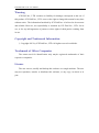
PMMS (Power Monitor & Management Solution) is a power management system
developed by ICP DAS. PMMS mainly consists of two parts: PMC-5141 (Power
Meter Concentrator) and ICP DAS Compact Power Meters. PMC-5141 connects to
ICP DAS compact power meter PM-213x and PM-311x via RS-485 to read the
power data of the devices; and then save the power data and send the data to
back-end FTP Server or SCADA software for further data integration or analysis.
PMC-5141 also provides power demand management and alarm notification
functions. With ICP DAS I/O modules (XW-107), according to the power demand
level it allows to turn on/off the devices to manage the power consumption of the
devices. In addition, PMC-5141 offers built-in Web Server, it allows users to connect
to PMC-5141 via browser to view power data or set up parameters for the controllers
or view the real-time or historical power data of the devices. By using Flash HMI
Tools function, users could easily design a specific power monitor page by a few
clicks on browsers. In addition, PMC-5141 offers Modbus TCP Slave function; it
allows SCADA software or HMI devices to connect to PMC-5141 to get the
front-end power meter data via Modbus TCP protocol.
During the whole process of system development, no programming is required; it
takes a few clicks on web page to complete settings and to store the power data of the
devices in the database for further analysis.
System Architecture:
http://www.icpdas.com
1
ICP DAS PMC-5141 User Manual
PMC-5141(Power Meter Concentrator) Features:
Built-in Web Server allows to set up the parameters of the front-end power
meters and view power data via browsers
Immediately display power data in real-time trend or historical trend
Offers power data report generator function
Offers alarm notification and power demand management function
Read power data of the front-end power meters and save the data in CSV file
format
Regularly send back power data to back-end FTP Server software for data
aggregation and analysis
Offers Modbus TCP Slave function that allows seamless integration with
SCADA software
Offers Flash HMI Tools for easy HMI interface design
Integrate ICP DAS I/O modules (XW-107)
Offers access management function
This document is intended to provide guidelines for PMC-5141.
http://www.icpdas.com
2
ICP DAS PMC-5141 User Manual
2
Before Installation
Before installing PMC-5141, please finish the hardware installation of the
PM-2133 / PM-2134 / PM-311x, and make sure all wiring connections are
accurate (please refer to PM-2133/PM-2134/PM-311x user manual).
PMC-5141 allows to connect with up to 16 power meters. The Modbus
address range of the power meter is from 1~64, please make sure the Modbus
address you set does not exceed 64.
Modify PMC-5141‘s network settings to fit current network environment
settings, and the default network settings of PMC-5141 is as follow:
IP:192.168.255.1
Subnet mask:255.255.0.0
Gateway address:192.168.0.1
DNS Server address:n/a
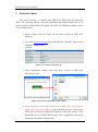
Steps:
(1) Modify the network settings of the PC or Notebook to be the same network
segment as PMC-5141. For example:
IP:192.168.255.2
Subnet mask:255.255.0.0
Gateway address:192.168.0.1
(2) Connect PMC-5141 LAN1 with PC by network cable. (PMC-5141 is capable
of auto-crossover)
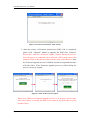
(3) Start the browse and input http://192.168.255.1 in the address bar.
(4) Input default administrator password “Admin” to login into the page.
(5) After login in PMC-5141 web page, go to System SettingBasic
SettingNetwork Setting, modify the network setting to fit current network
environment.
(6) Save the settings and connect PMC-5141 to the network.
http://www.icpdas.com
3
ICP DAS PMC-5141 User Manual
3
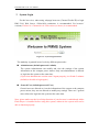
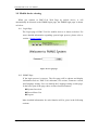
System Login
For the best view, when using webpage browsers (Chrome/Firefox/IE) to login
PMC-5141 Web Server, 1280x1024 resolutions is recommended. For browser’
versions, Firefox3.6 / Chrome14.0.8 / IE8 version (or above) is recommended.
Figure 3-1: System Login Interface
The authority is granted in two levels by different passwords:
Administrator (default password: Admin)
The system Administrator can modify and view the settings of the system
information or the compact power meters. Only one administrator is allowed
to login into the system at the same time.
(If previous administrator session wasn’t logout properly, it will take 5 minutes
(default) to be able to login again.)
General User (default password: User)
General users are allowed to view the information of the system or the compact
power meters, they are not allowed to modify any settings. There are 5 general
users allowed to login into the system at the same time.
Note: please make sure the Java Script function of your browser is enabled and Adobe
Flash Player is installed before using this system, otherwise the system will not be
able to function properly.
http://www.icpdas.com
4
ICP DAS PMC-5141 User Manual
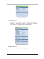
4
System HOME Page
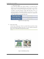
Figure 4-1: Default HOME Page
Figure 4-2: Flash HMI HOME Page
After login into the page, according to different access authority level, you will
be directed to different pages:
Login as Administrator:The default home page (figure 4-1) will be loaded,
it will display current information of the power meters that are connected to
the system; the power information will be updated automatically every 20
seconds. On this page, users could view brief summary of power data and
contract capacity in real time. In addition, carbohydrate emission
information will be displayed according to the electricity consumption of
the power meter.
Login as General User:The default home page will be displayed according
to previously set by the administrator. When a Flash HMI home page
project is set as the home page (please refer to Flash HMI Tools Quick
Start), the system will load the preset HMI home page project as the home
page(Figure 4-2). If no Flash HI home page is assigned, the system will
load default home page (Figure 4-1).
Please note: if this is your first time login into the system, please search the
power meter in advance (please refer to power meter setting section), the power
data of the power meters can’t be displayed without performing searching in
advance.
http://www.icpdas.com
5
ICP DAS PMC-5141 User Manual
The 6 function tabs on web page upper region are as below:
Home
System
Power Meter
Alarm
Event Log
Logout
The following section will give more detailed information for each function tab.
http://www.icpdas.com
6
ICP DAS PMC-5141 User Manual
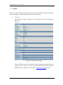
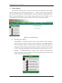
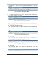
5
System
There are 6 pages under the System page: Overview, Basic Setting, Advanced Setting,
Security Setting, I/O Module Setting, and Home Page Setting.
5.1
Overview
On the Overview page, it displays overview information for each setting on
PMC-5141.
Figure 5-1: System Overview Page
User could check out the information for each setting and perform firmware
upgrade on this page. For more detailed information about firmware
upgrade function, please refer to chapter 9 Firmware Upgrade section.
http://www.icpdas.com
7
ICP DAS PMC-5141 User Manual
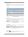
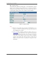
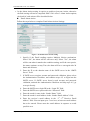
5.2
Basic Setting
On Basic Setting page, the user could modify the Nickname, Language,
Date/Time of the system, Network Setting and COM Port Setting of the
PMC-5141.
Figure 5-2: Basic Setting Page
Nickname
The user could assign a nickname to the PMC-5141, the nickname could be
input and displayed in multiple languages. After you make a change to the
nickname, please click “Save” button to save the change.
Figure 5-3: Nickname Setting
Language
The Language setting section allows user to setup the default language
display when the user login into the system.
Figure 5-4: Language Setting
Date/Time
Date: Select … button to bring up the calendar window (Figure 5-5), click
the date on the calendar to set up the date setting.
http://www.icpdas.com
8
ICP DAS PMC-5141 User Manual
Time: Select the hour/minute/second from the dropdown list. After you
finish the setting, click on “Save” button to save the changes.
Figure 5-5: Time Setting
Network Setting
Each time when get into this page, it will automatically read and display
current network setting of the PMC-5141. After finishing modification of
the network setting, click on “Save” button to save the changes.
Figure 5-6: Networking Setting
Note:
1. The terminal for outer network connection on PMC-5141 is LAN1;
therefore input the parameters of LAN1 network settings in this section.
2. If fail to setup the network, the network setting will be set as previous
value. After successful modifying the network setting, it will
automatically logout and transfer to new address. If it doesn’t transfer
to new address automatically, please input the new address in the
address bar and reconnect again.
http://www.icpdas.com
9
ICP DAS PMC-5141 User Manual
COM Port Setting
After getting into COM Port Setting page, it will automatically read and
display current COM Port Setting on PMC-5141. To modify the COM Port
Setting, please input Baudrate, Stop bit and Timeout (greater than 600ms is
recommended), and then click on “Save” button to save the changes.
Figure 5-7: COM Port Setting
Note:
(1) PM-213x series product does not support 115200 Baudrate, if you
intend to use PM-213x and PM-311x at the same time, please do
not set Baudrate to be 115200.
(2) After you finish modifying COM Port settings, please go to
“Power Metter” page and perform “Scan” again to renew the latest
power meter information and make sure the settings of COM Port
is the same as the settings of power meters (such as Baudrate
settings). If the settings don’t match each other, it might result in
failing to scan power meters or getting the wrong power meter
information.
http://www.icpdas.com
10
ICP DAS PMC-5141 User Manual
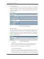
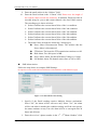
5.3
Advanced Setting
The “Advanced Settings” section includes: Data Logging, Event Logging,
Remote FTP Setting, Contract Capacity Setting, Demand Interval Setting
and Carbon Footprint Setting. The detailed information for each setting is
described as follow:
Figure 5-8: Advanced Setting Page
Data Logging
In “Data Logging” section, you can set up the schedule for PMC-5141 to
record power values of power meters. To enable Data Logging”, please
click on the check box in front to enable the function. To disable the
function, please uncheck and click on “Save” button. The “Data Logging”
interface is shown as below:
Figure 5-9: Data Logging
Log Rate
In this section you can set up the interval to record each data. The Log
data is an average value of a set of data acquired during the log rate
interval. You can set the Log Rate as 5/10/15 minutes.
Log File Retention Time
In this section you can set up the retention time of the log file. The files
exceed the retention time will be automatically removed. If an error is
occurred during the process of sending back the files, the retention time
http://www.icpdas.com
11
ICP DAS PMC-5141 User Manual
will be automatically extended 10 more days. After the sending process
is back to normal, the retention time will be automatically adjusted to
original setting. The “Log File Retention Time” can be set as 10/30/50
days.
File Name Format
Set up the file name format for the data log file. The file name format
can be set as YYYY-MM-DD or DD-MM-YYYY formats。
(Y: Year,M: Month,D: Date)
End of Line Character
Set up End of Line Character. The character can be set according to the
system is using; it can be set as: CRLF(Windows), LF(Unix or Linux) or
CR(Mac) formats.
Event Logging
The Event Logging function allows to record the information about
significant system events. To enable “Event Logging”, please click on the
check box in front and save the settings to enable the function. To disable
this function, uncheck and save the settings. When the Event Logging
function is disabled, it will still keep on recording the system events,
however, it will not perform any operation to upload or delete the files. The
settings of Event Logging are described as below:
Figure 5-10: Event Logging
Log File Retention Time
Set up the retention time of the event log file. If an error is occurred
during the process of sending back the files, the retention time will be
automatically extended 1 more month. After the sending process is back
to normal, the retention time will be automatically adjusted to original
setting.
Time to Upload
Set up the days to upload the event log file, the minimum time interval to
upload the file is 1 day and the maximum interval is 99 days.
http://www.icpdas.com
12
ICP DAS PMC-5141 User Manual
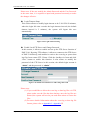
Remote FTP Setting
In the Remote FTP Setting section, it allows to set up the backend server
that is going to receive the data log and event log files. To enable this
function please click the checkbox in front of the “Remote FTP Setting” and
input the IP address, port and password of the remote FTP; save the settings
and it is ready for use. If this function is disabled, or there is a mistake of
the settings, the data log and event log files will not be able to transferred.
Figure 5-11: Remote FTP Setting
Contract Capacity Setting
The contract capacity with electric utility company can be set in this section.
Enable the Contract Capacity Setting, and then the comparison chart of
Contract Capacity and the Predicted Demand will be displayed in the Home
page.
Figure 5-12: Contract Capacity Setting
Demand Interval Setting
Input the Calculation Interval of the demand, the default interval is 15
minutes. The Calculation Interval of the demand can be set as 15 minutes/
30 minutes/ 60 minutes.
Figure 5-13: Demand Interval Setting
Carbon Footprint Setting
Set up the factor of Carbon Footprint. Please follow the global statistics data
published by International Energy Agency (IEA ) to set up the carbon
footprint factors.
Figure 5-14:Carbon Footprint Setting
http://www.icpdas.com
13
ICP DAS PMC-5141 User Manual
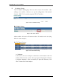
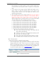
5.4
Security Setting
In the Security Setting section, it allows to:
Modify the password for administrator or general user
Change the settings for Login Timeout
Enable or disable Local FTP Server
Modify the password of Local FTP Server
Figure 5-15: Security Setting
Admin Password
The Admin Password is limited to 20 characters, and the default
Administrator Password is: “Admin”.
Note: Avoid using the system characters: “#” and “?” as the password.
Figure 5-16: Password Setting for Administrator
User Password
The User Password is limited to 20 characters, and the default User
Password is: “User”.
Note: Avoid using the system characters: “#” and “?” as the password.
Figure 5-17: Password Setting for User
http://www.icpdas.com
14
ICP DAS PMC-5141 User Manual
Please note: If the user modify the Admin Password and the User Password
at the same time, it is required to input both password accurately to make
the changes effective.
Login Timeout Setup
This section allows to modify login timeout to be 5/10/15/20/30 minutes,
when the login idle time exceeds the login timeout interval (the default
timeout interval is 5 minutes), the system will logout this user
automatically.
Figure 5-18: Login Timeout Setting
Enable Local FTP Server and Change Password
In this section, it allows to enable and set up the FTP Server function of
PMC-5141. By using FTP software, it allows to connect to the FTP Server
of PMC-5141directly, and enables to retrieve the event log or power data
log files from remote FTP Clients. Click the checkbox in front and click
“Save” button to enable this function. It also allows to modify the
password of the FTP Server in this section; the default login account is
“admin” and the password is “admin”.
Figure 5-19: Enable Local FTP Server and Change Password
Please note:
(1) If you would like to delete the event log or data log files via FTP,
please make sure the files has been backup, once the log files are
deleted, the system will not let you undo that action or restore the
files.
(2) For more detailed information about the event log or data log file
format, please refer to Appendix I ~ Appendix III.
http://www.icpdas.com
15
ICP DAS PMC-5141 User Manual
5.5
I/O Module Setting
The I/O Module Setting page allows to add or remove I/O modules. After
adding a new module, it allows to set up the configuration of the module
channels. (PMC-5141 currently supports XW-107 module.)
Figure 5-20: I/O Module Setting
Module Setting
Figure 5-21: Add a module
Add a module: click on “Add” button to add an I/O module to the list (using
XW-107 as an example).
DI Channel Setting
Figure 5-22: DI Channel Setting
Nickname
In this section, the user could give a nickname to a DI channel on the I/O
modules. The nickname section allows to input and display the nickname
in multiple languages. After you modify or input the nickname, click
“Save” button to save the changes.
http://www.icpdas.com
16
ICP DAS PMC-5141 User Manual
DO Channel Setting
Figure 5-23: DO Channel Setting
Nickname
In this section, the user could give a nickname to a DO channel on the
I/O modules. The nickname section allows to input and display the
nicknames in multiple languages. After you modify or input the
nickname, click “Save” button to save the changes.
Figure 5-24: Nickname Setting
Power On Value
In this section it allows to set the initial value for the DO channels in the
“Power On Value” field. The system will output this value when being
powered on. Click “Save” button to save the changes.
Figure 5-25: Power On Value Setting
http://www.icpdas.com
17
ICP DAS PMC-5141 User Manual
Enable Pulse Output
If you check the Enable pulse output checkbox, it will allow this DO
channel to perform pulse output and form a periodic pulse cycle. In Pulse
Output mode, the selected DO channel will generate a square wave
according to specified parameters (Pulse High and Pulse Low). It is
required to input the Pulse High and Pulse Low. The unit is 1 second.
Pulse High indicates the “ON” time duration and Pulse Low indicates the
“OFF” time duration in a periodic Pulse cycle.
Figure 5-26: Pulse Output Setting
5.6
Home Page Setting
In Home Page Setting page, it allows to perform Home page edition, design
and the management of Home page project. For more detailed information,
please refer to Flash HMI Tools Quick Start manual.
Figure 5-27: HOME Page Setting
http://www.icpdas.com
18
ICP DAS PMC-5141 User Manual
6
Power Meter
On the Power Meter page, a list for all power meters connected to the system
will be displayed on the left region (Figure 6-1). Click on one Power meter, there
will be three tabs shows on the right region: Overview, Parameter Setting and View
Data. For the initialization of the system, please click on “Scan” (Figure 6-2) to
perform the first scan of the system in order to build a list of the power meters.
Figure 6-1: Power Meter Page
6.1
Scan the Power Meters
After adding or removing a power meter, please perform “Scan” again to
renew the power meter list. If the “Scan” operation is executed accurately,
the user would be able to select the power meter for power data query or
settings. If it fails to scan the power meters or there is no power meter exists,
a “N/A” message will appear and will not be able to perform any review or
settings. If adding/removing a power meter without performing the
“Scan” operation, the user will not be able to get into the power meter node
and an error message will appear.
Figure 6-2: Scan the Power Meters
http://www.icpdas.com
19
ICP DAS PMC-5141 User Manual
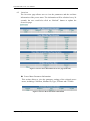
6.2
Overview
The Overview page allows user to view the parameters and the real-time
information of the power meter. The information will be refreshed every 20
seconds, the user could also click on “Refresh” button to update the
Overview page.
Figure 6-3: Power meter information Overview page (PM-3112)
Power Meter Parameter Information
This section allows to view the parameter settings of the selected power
meter, including: COM Port, Modbus ID, Type, PT Ratio and CT Ratio.
Figure 6-4: Power Meter Parameter Information
http://www.icpdas.com
20
ICP DAS PMC-5141 User Manual
Power Meter Real Time Information
Figure 6-5: Power Meter Real Time Information (PM-2133)
Figure 6-6: Power Meter Real Time Information (PM-2134)
Figure 6-7: Power Meter Real Time Information (PM-3112)
http://www.icpdas.com
21
ICP DAS PMC-5141 User Manual
In this section, it allows to view the real time information of the selected
power meter. For PM-2133, it will display the real time information of
Phase A, Phase B and Phase C (Figure 6-5). For PM-2134, it will display
the real time information of Channel 1, Channel 2, Channel 3 and Channel 4
(Figure 6-6). And for PM-3112, it will display the real time information of
Channel 1, Channel 2 (Figure 6-7).
Reset Power Meter Accumulated Information
The【Reset】button will appear when login as an administrator; it allows to
reset all accumulated information fields to their default values (zero); this
function is not available if login as a general user.
Power Meter DO Status (apply to PM-311x series only)
Figure 6-8: Power Meter DO Status
In this section, you can view the DO status of the specified power meter. If
you login as Administrator, you can directly control the output value of the
DO channels as well. If you login as a general user, you can view the DO
status only without being able to perform any modification.
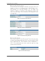
6.3
Parameter Setting
On the “Parameter Setting” page, it allows to modify the nickname and the
transformation ratio value of the parameter and its channels, as shown
below:
Figure 6-9: Parameter Setting Page (PM-3112)
http://www.icpdas.com
22
ICP DAS PMC-5141 User Manual
Power Meter Parameter Setting
In this section, the user could give a nickname to the power meter or its
channels, as shown in the following figures: PM-2133(Figure 6-10)、
PM-2134(Figure 6-11) and PM-3112(Figure 6-12). The length of the
nickname is limited to 30 characters, after finishing the settings, click
“Save” to save the changes. The new nicknames will be displayed on screen
or in logger data.
Figure 6-10: Nickname Setting (PM-2133)
Figure 6-11: Nickname Setting (PM-2134)
Figure 6-12: Nickname Setting (PM-3112)
Power Meter Property
In this section, it allows to set the PT ratio and CT ratio of the power meter
as needed. After finishing setting, click “Save” to save the changes. The PT
ratio is ranged from 0.01 ~ 655.35 and the CT ratio is ranged from 1 ~
65535. If the transformation ratio value exceeds the range, the saving
operation will not be allowed.
Figure 6-13: Power Meter Property
http://www.icpdas.com
23
ICP DAS PMC-5141 User Manual
Power Meter DO setting ( PM-311x series)
In this section you can give a nickname and initial power on default DO
values to the specified power meter. After finishing the settings, click
“Save” to save the nickname and power on default values. The nickname
could be input and displayed in multiple languages. After the power on
values being set, the system will output the pre-set initial status when being
powered on.
Figure 6-14:Power Meter DO Setting
6.4
View Data
On the “View Data” page, it provides a brief overview information of
electricity usage information, including: daily report, monthly report, real
time chart, historical table and historical chart, as shown below:
Figure 6-15: View Data
Statistics Report
This function provides daily and monthly report of the power data. To open
a report, please select the Report Type (Figure 6-16), and then select the
Report Date (Figure 6-17), click on “Open Report”. If the file does not exist
in the input date or exceeds the date of the range, a message of “File not
found” will appear.
http://www.icpdas.com
24
ICP DAS PMC-5141 User Manual
For PM-2133、PM-2134 and PM-3112 are equipped with different number
of channels, the report format will be different
PM-2133 report please refer to Figure 6-18
PM-2134 report please refer to Figure 6-19
PM-3112 report please refer to Figure 6-20
Figure 6-16: Report Type
Figure 6-17: Report Date
Figure 6-18: PM-2133 Report
http://www.icpdas.com
25
ICP DAS PMC-5141 User Manual
Figure 6-19: PM-2134 Report
Figure 6-20: PM-3112 Report
http://www.icpdas.com
26
ICP DAS PMC-5141 User Manual
Real Time Data
In this section it allows to query various electricity data. Select the Type
(Figure 6-16) and then click on “View”. The data chart will be displayed; as
shown on Figure 6-22(PM-213x) and Figure 6-23(PM-3112). It allows to
view real time chart one type each time, if a second type is viewed; the
previous chart will be closed automatically and will display the real time
chart of the second type only. The user could select a specific type to view
the real time chart. The refresh rate of the chart is 5 seconds. Click on the
“Stop” button on the left, it will stop refreshing the chart and will display
the chart data of the previous 25 minutes. The user could drag and move on
the chart to adjust the viewing range. Press “Start” to continue to refresh the
chart. To view the value on the marker point, move the mouse cursor close
to the marker point, the value will be displayed.
Figure 6-21: Types of the Real Time Chart
Figure 6-22: Real Time Chart (PM-213x)
http://www.icpdas.com
27
ICP DAS PMC-5141 User Manual
Figure 6-23: Real Time Chart (PM-3112)
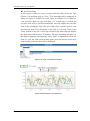
Historical Data
Select the Date and Type that is going to query the data and then click on
the “Query” button, the data of the specified date and type will be displayed.
If the file does not exist in the input date or exceeds the date of the file
storage range, a message of “File not found” will appear. To view the
historical chart, please click on “Historical Chart”. (Note: it has to
successfully query the file to view the historical chart)
Figure 6-24: Historical Data
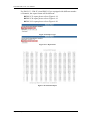
Figure 6-25: Historical Data Table (PM-213x)
http://www.icpdas.com
28
ICP DAS PMC-5141 User Manual
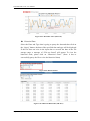
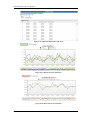
Figure 6-26: Historical Data Table (PM-3112)
Figure 6-27: Historical Chart (PM-213x)
Figure 6-28: Historical Chart (PM-3112)
http://www.icpdas.com
29
ICP DAS PMC-5141 User Manual
It allows to view historical data chart of specific type. The user could select
the range on the below region or drag and move on the chart to adjust the
viewing range. To reset the chart to original view, click on the “Reset”
button on the left upper region. Move the mouse cursor close to the marker
point, the value will be displayed.
http://www.icpdas.com
30
ICP DAS PMC-5141 User Manual
7 Alarm
It allows to set up to 6 IF-THEN-ELSE Alarm Rules. When the Alarm Rule
condition is satisfied, it will send out the pre-set Alarm message or perform the
pre-set Action. There are 5 types of Alarm triggered condition: Power Meter
Disconnection Alarm, FTP Alarm, Disk Alarm, Power Meter Alarm and I/O Module
Alarm. The Alarm setup page is shown as below:
Figure 7-1: Alarm Setting Page
Please follow the steps below to set up the Alarm settings:
i. In the “Alarm Amount” field, specify the total number of alarm rule you are
going to use from the dropdown list.
Figure 7-2: Setup total number of alarms
ii. In the “Alarm Index” field, specify the alarm index number to be set up from the
dropdown list.
iii. In the “Alarm Condition Setting” section, select the alarm condition mode, the
alarm condition mode includes the following options: Power Meter
Disconnection Alarm, FTP Alarm, Disk Alarm, Power Meter Alarm and I/O
Module Alarm. After finishing the setting, click on “Add” button to add the new
condition to the Alarm Condition List (Figure 7-3). It is required to add at least
http://www.icpdas.com
31
ICP DAS PMC-5141 User Manual
one condition or it will fail to save the condition, maximum 6 sets of conditions
is allowed.
Figure 7-3: Add Power Meter Alarm Condition
iv. To delete the condition, click on the “Delete” button next to the Alarm condition
in the “Alarm Condition List” section.
Figure 7-4: Delete Power Meter Alarm Condition
PMC-5141 offers 5 Alarm Condition options; the detail of each condition will
be described below:
Power Meter Disconnection Alarm
After successfully add the Power Meter Disconnection Alarm condition, when
Power Meter is disconnected and fail to read data up to the specified time period
(10 minutes/20 minutes/30 minutes/1 hour/ 6 hours), the alarm condition will be
True.
Figure 7-5: Power Meter Disconnection Alarm
FTP Alarm
After successfully adding a FTP Alarm, when FTP fails to transmit up to 12
hours/ 24 hours/48 hours, the alarm condition will be True.
Figure 7-6: FTP Alarm
Disk Alarm
After successfully adding a Disk Alarm, when the disk space is less than
50MB/100MB/500MB, the alarm condition will be True.
Figure 7-7: Disk Alarm
http://www.icpdas.com
32
ICP DAS PMC-5141 User Manual
Power Meter Alarm
The condition of Power Meter Alarm can be set as Predicted Demand, Voltage
or Current. Set up the expression statement for the power meter alarm. Select an
operator from “=”,”>=” or “<=”, and an evaluation value has to be specified; if
the power meter alarm match the evaluation criteria, the result of this alarm
condition will be “True”
Figure 7-8: Power Meter Alarm
【About Deadband Setting】
In order to avoid the signal oscillation of the Predicted Demand/Voltage/
Current that may causes the instability of the status changes and result in the
alarm being triggered too easily, you can set up a Deadband value to reduce the
oscillation effect.
Deadband Examples:
Assume the Current Condition is set as [ Current >=10A, Deadband :
2A], when current exceeds 10A, the alarm will be triggered and the
alarm won’t be dismissed until the current drop below 8A.
Condition:Current >= 10 A
10A
Deadband = 2 A
8A
False
True
False
Assume the Current Condition is set as [ Current <=10A, Deadband :
2A], when current is lower than 10A, the alarm will be triggered and
the alarm won’t be dismissed until the current reaches 12A.
http://www.icpdas.com
33
ICP DAS PMC-5141 User Manual
Condition:Current <= 10 A
12A
Deadband = 2 A
10A
False
False
True
Assume the Current Condition is set as [Current =10A, Deadband :
2A], when current falls between 8A to 12A, the alarm will be
triggered.
Condition:Current = 10 A
Deadband = 2 A
12A
10A
8A
False
True
False
True
False
I/O Module Alarm
After successfully adding an I/O Module Alarm, when the status of the channel
value matches the condition setting, the alarm condition will be True. If there is
no pre-set I/O module, the DI status can’t be set as a condition, and a message
“Fails to set up the Alarm Condition due to no I/O module exists” will appears.
To set up the I/O module, please refer to I/O Module Setting Section.
Please Note: Currently PMC-5141 support XW-107 I/O module only.
Figure 7-9: I/O Module DI Alarm
http://www.icpdas.com
34
ICP DAS PMC-5141 User Manual
v. In the Alarm Action setting, it requires to enable at least one Action, otherwise
the Rule setting will not be completed. PMC-5141 offers 3 Alarm Action options;
the detail of each action will be described below:
Email Alarm Action
Follow the steps below to complete Email Alarm Action Settings:
Figure 7-10: Email Alarm Action Setting
1. Specify if the Email sending requires Multiple Notices mechanism.
Select “No”, the alarm will be sent once only. Select “Yes”, the alarm
will be sent when it matches the condition setting, and if the error persist,
the status continues to stay True, the alarm will be re-sent again after 24
hours and 48 hours.
2. Enter the IP or the domain name of the SMTP server in the “SMTP
Server” field.
3. If SMTP server requires account and password validation, please select
the Authentication Checkbox, and continue steps 4~5 to login into the
SMTP server. If SMTP server doesn’t need account and password
4.
5.
6.
7.
8.
validation, uncheck the Authentication Checkbox and skip steps 4~5, go
to step 6 directly.
Enter the SMTP server login ID in the “Login ID” field.
Enter the SMTP server password in the “Password” field.
Enter the sender’s name in the “Sender Name” field.
Enter the sender’s email address in the “Sender Email Address” field.
Enter the receiver’s email address in the “1st ~5th Receiver Email
address” field. You can input up to 5 receivers; at least one email address
has to be entered. Please enter the email address in sequence to avoid
possible error.
http://www.icpdas.com
35
ICP DAS PMC-5141 User Manual
9. Enter the email subject in the “Subject” field.
10. Enter the Email content in the “Content” field. Please note: the length of
the content cannot exceed 160 characters. In addition, Email provides an
encoded string for you to add current channel value into Email content.
The encoding tag is shown as below:
$value1 indicates the current Alarm Value of the 1st condition.
$value2 indicates the current Alarm Value of the 2nd condition.
$value3 indicates the current Alarm Value of the 3rd condition.
$value4 indicates the current Alarm Value of the 4th condition.
$value5 indicates the current Alarm Value of the 5th condition.
$value6 indicates the current Alarm Value of the 6th condition.
The Alarm Value includes the following 5 Alarm types:
Power Meter Disconnection Alarm: The minutes that the
Power Meter is disconnected
FTP Alarm: The hours the FTP transmission continues to fail
Disk Alarm: Free disk space in MB
Power Meter Alarm: Predicted Demand, Voltage or Current
I/O Module Alarm: DI channel status (show as ON or OFF)
SMS Alarm Action
Follow the steps below to complete SMS Settings:
(It requires to work with ICP DAS GTM-201-USB modem to send SMS messages)
Figure 7-11: SMS Alarm Action Setting
1. Specify if the Email sending requires Multiple Notices mechanism.
Select “No”, the alarm will be sent once only. Select “Yes”, the alarm
will be sent when it matches the condition setting, and if the error persist,
the status continues to stay True, the alarm will be re-sent again after 24
hours and 48 hours.
2. Enter the receiver’s phone number in the “1st ~5th Phone Number” field.
http://www.icpdas.com
36
ICP DAS PMC-5141 User Manual
You can input up to 5 phone numbers, at least one phone number has to
be entered. Please enter the phone number in sequence to avoid possible
error.
3. If the content of the message includes English and numbers only, it
doesn’t require to enable the Unicode option. If the content of the
message includes characters other than English and numbers, please
enable the Unicode option.
4. Enter the SMS content in the “Content” field. Please note: the length of
the content cannot exceed 160 characters. If the Unicode mode is
adopted, the length of the content cannot exceed 70 characters. In
addition, SMS provides an encoded string for you to add current channel
value into SMS content. The encoding tag is shown as below:
$value1 indicates the current Alarm Value of the 1st condition.
$value2 indicates the current Alarm Value of the 2nd condition.
$value3 indicates the current Alarm Value of the 3rd condition.
$value4 indicates the current Alarm Value of the 4th condition.
$value5 indicates the current Alarm Value of the 5th condition.
$value6 indicates the current Alarm Value of the 6th condition.
The Alarm Value includes the following 5 Alarm types:
Power Meter Disconnection Alarm: The minutes that the
Power Meter is disconnected
FTP Alarm: The hours the FTP transmission continues to fail
Disk Alarm: Free disk space in MB
Power Meter Alarm: Predicted Demand, Voltage or Current
I/O Module Alarm: DI channel status (show as ON or OFF)
DO Alarm Action
Follow the steps below to enable DO Action settings:
1. Select the output status of the specified DO channel to be OFF, ON or Pulse
Output, and then click “Add”. If there is no pre-set I/O module or connected
PM-311x, the DO status can’t be set as a Alarm Action, and a message “Fails
to set up the DO Alarm Action due to no I/O module exists” will appears. To
set up the I/O module, please refer to I/O Module Setting Section.
Figure 7-12: Add a DO Alarm Action
http://www.icpdas.com
37
ICP DAS PMC-5141 User Manual
2. To delete the action, click on the “Delete” button in the “DO Action List” to
delete the DO Action (Figure 7-13).
Figure 7-13: Delete a DO Alarm Action
http://www.icpdas.com
38
ICP DAS PMC-5141 User Manual
8
Event Log
PMC-5141 provides page to view the Event logger information. You can visit the
page for the system messages or operation information for your reference. The
information PMC-5141 will record in the log file are as follows:
(1) The Login/Logout events for Administrator.
(2) The events to modify the PMC-5141 system settings.
(3) The event that PMC-5141 is failed to get the power meter data.
(4) The event to modify the CT/PT values of the power meters by PMC-5141.
(5) The event that PMC-5141 is failed to send the alarm messages by Email or
SMS.
(6) The event that PMC-5141 is failed to send back the power data files to FTP
server.
(7) The event about the status of the firmware download process..
(8) The event of successful or failed update attempts of the PMC-5141 firmware
upgrade.
Figure 8-1: Event Log page
http://www.icpdas.com
39
ICP DAS PMC-5141 User Manual
9
Firmware Update
You can use browser to connect with PMC-5141 WEB page to update the
PMC-5141 Firmware directly. After the completion of Firmware update process, it
doesn’t require to reboot PMC-5141 again. The PMC-5141 Firmware update process
is described as below:
1. Please contact with ICP DAS for the latest version of PMC-5141
firmware.
2. Go to the System Overview Page, and click the “Upgrade” button in the
Firmware Version field.
Figure 9-1: Firmware Upgrade page
3. Click “Download” button; select the latest version of PMC-5141
Firmware you get.
Figure 9-2: Firmware Download to PMC-5141(1)
4. When the process of Firmware download to PMC-5141 is in progress,
please don’t close the window. If the download process is successful,
PMC-5141 will start to update the Firmware to the new version. If the
download process is failed, the message will be logged and system will
display the Download window again.
http://www.icpdas.com
40
ICP DAS PMC-5141 User Manual
Figure 9-3: Firmware Download to PMC-5141(2)
5. After the process of Firmware download to PMC-5141 is completed,
please click “Upgrade” button to upgrade the PMC-5141 firmware.
Please don’t close the “Firmware Update” window during the process.
After the process is completed, please click the “OK” button, remove the
temporary files of the Browser, and clear the cache of the Browser. Now
the Firmware upgrade process is finished, and the new updated firmware
will take effect. If the Firmware upgrade process is failed during the
process, please try it again.
Figure 9-4: PMC-5141 Firmware Update
Please note: When the Firmware upgrade process is in progress, please don’t
close any window or modify the PMC-5141 setting at the same time to avoid
possible errors.
http://www.icpdas.com
41
ICP DAS PMC-5141 User Manual
10 Mobile device viewing
When you connect to PMC-5141 Web Page by mobile device, it will
automatically be directed to the PMMS login page, the PMMS login page is shown
as below:
10.1 Login Page
The Login page of PMC-5141 for mobile devices is shown as below. For
more detailed information regarding system login process, please refer to
section “System Login”.
Figure 10-1: Login page
10.2 HOME Page
If the login process is success. The first page will be shown and display
information such as: PMC-5141 nickname, OS version, Firmware version,
and Language setting. User can modify the Language setting on this page.
In the lower part of the page, there are three function buttons:
System Overview
Power Meter List
Logout
More detailed information for each function will be given in the following
sections.
http://www.icpdas.com
42
ICP DAS PMC-5141 User Manual
Figure 10-2: System page
10.3 System Overview
In the System Overview page, you can get the detailed system information
of PMC-5141 controller shown as below. To leave this page, click on the
“Back” button in the lower part to return to the System page.
Figure 10-3: System Overview page
10.4 Power Meter List
When you enter the Power Meter List page, a list of the power meters that
are currently connected with the PMC-5141 will show:
http://www.icpdas.com
43
ICP DAS PMC-5141 User Manual
Figure 10-4: Power Meter List page
Click the power meter on the list, and then the Power Meter Overview page
for that meter will be shown. There are four buttons in the page: “Power
Meter Information”, “Realtime chart”, “Back” and “Home”. “Power Meter
Information” and “Realtime chart” buttons are for power meter value
display.
Figure 10-5: Power Meter Overview page
Click on the button to view the power value of the specified power meter.
Detailed description is as below:
Power Meter Information
After getting into the Power Meter Information page, the parameters of the
specified power meter will be displayed in the upper part of this page. The
http://www.icpdas.com
44
ICP DAS PMC-5141 User Manual
lower part is for the power value display section. It offers two options:
“Channel” or ”Type” mode for power value display. If the “Channel”
mode is selected, the interface will be shown like Figure 10-6. You can
select any channel on the channel list, and then the real time power value
of that specified channel for the power meter will be shown as Figure 10-7.
If you select “Type” mode, the interface will be shown like Figure 10-8.
All data is the power value display section will be updated automatically
every 20 seconds.
Figure 10-6: Power Meter Information page
Figure 10-7: Channel mode
http://www.icpdas.com
Figure 10-8: Type mode
45
ICP DAS PMC-5141 User Manual
Realtime chart
User can select Realtime Chart to display the realtime power value by
specified Chart component. Get into the Realtime Chart page, you will see
a list of various power value type options shown as Figure 10-9. It only
allows to show one Realtime Chart for a specified power value type at the
same time, shown as Figure 10-10. If you already open a Realtime Chart
for a power value type, and then you continue to open the second Realtime
Chart for other power value type, the first Realtime Chart will be closed
automatically. The data update rate in Realtime Chart is about 5 seconds.
You can click the ”Stop” button in the upper-left part of the Chart to
suspend the data updating. To resume the update process, click “Start”
button to continue the data update of the Realtime Chart.
Figure 10-9: Realtime Chart (1)
Figure 10-10: Realtime Chart (2)
http://www.icpdas.com
46
ICP DAS PMC-5141 User Manual
Appendix I:The file structure of the data file directory
The power data logger files, power report files and event logger files that are
generated by PMC-5141 will all be saved in the Micro-SD card. It allows to connect
with PMC-5141’s built-in FTP server to retrieve these data files at PC side via FTP
utility. The default FTP login directory is the root directory of the Micro-SD card.
Power data logger files are saved in the “Log” directory. Based on the power
meter ID, each power meter has its own directory for the data logger files saving.
The following is an example of the file structure in the data logger file directory.
Power meter information file
Log \ 01A3851F140000D3[2133]7 \_info.txt
History power meter data file
Log \ 01A3851F140000D3[2133]7 \ 2011-9-19.csv Power meter data file for 2011/9/19
Daily Report
Log \ 01A3851F140000D3[2133]7 \ 2011-9-19Rpt.csv Daily power report for 2011/9/19
Monthly Report
Log \ 01A3851F140000D3[2133]7 \ 2011-9Rpt.csv Monthly power report for 2011/9
01A3851F140000D3[2133]7 is the unique identification number for the power
meter. [2133] indicates the type of power meter (”2133” is for PM-2133, “2134”
is for PM-2134, “3112” is for PM-3112), 7 is the Modbus address of the power
meter. A date tag ”2011-9-19”(the date the file being created) is appended ahead
of the file name . The file “_info.txt” is used to record the nicknames of the
power meters that are connected to the PMC-5141 and their mapping data with
PMC-5141.
Event logger files are saved in the “EventLog” directory. The following is an
example of the file structure in the event logger file directory.
EventLog \ Event_20110805143506
20110805143506 indicates that the first record time of the file starts from
2011/08/05 14:35:06.
http://www.icpdas.com
47
ICP DAS PMC-5141 User Manual
Appendix II:The format of the Power Logger Data file
The power data logger files generated by PMC-5141 are saved in CSV file
format. Each line represents one record; each field in the line is separated by a comma.
The data sequences from left to right in the line of the power data are as follows:
Date, Time, Power meter ID, Voltage(Ch1 or Phase A), Current(Ch1 or Phase A),
kW(Ch1 or Phase A), kvar(Ch1 or Phase A), kVA(Ch1 or Phase A), PF(Ch1 or Phase
A), kWh(Ch1 or Phase A), kvarh(Ch1 or Phase A), kVAh(Ch1 or Phase A), Daily tot.
Electricity(kWh;Ch1 or Phase A), Current demand(15/30/60mins;Ch1 or Phase A),
Voltage(Ch2 or Phase B), Current(Ch2 or Phase B), kW(Ch2 or Phase B), kvar(Ch2
or Phase B), kVA(Ch2 or Phase B), PF(Ch2 or Phase B), kWh(Ch2 or Phase B),
kvarh(Ch2 or Phase B), kVAh(Ch2 or Phase B), Daily tot. Electricity(kWh;Ch2 or
Phase B), Current demand(15/30/60mins;Ch2 or Phase B), Voltage(Ch3 or Phase C),
Current(Ch3 or Phase C), kW(Ch3 or Phase C), kvar(Ch3 or Phase C), kVA(Ch3 or
Phase C), PF(Ch3 or Phase C), kWh(Ch3 or Phase C), kvarh(Ch3 or Phase C),
kVAh(Ch3 or Phase C), Daily tot. Electricity(kWh;Ch3 or Phase C), Current
demand(15/30/60mins;Ch3 or Phase C), Voltage(Ch4 or Average), Current(Ch4 or
Average), kW(Ch4 or Average), kvar(Ch4 or Total), kVA(Ch4 or Total), PF(Ch4 or
Average), kWh(Ch4 or Total), kvarh(Ch4 or Total), kVAh(Ch4 or Total), Daily tot.
Electricity(kWh;Ch4 or Total), Current demand(15/30/60mins;Ch4 or Total),
The description above illustrates: Ch0/Ch1/Ch2/Ch3 is for 4/2 Loops (Channels) 1
Phase power meter (PM-2134/PM-311x), Average/Total is for 3 Phase power meter
(PM-2133).
http://www.icpdas.com
48
ICP DAS PMC-5141 User Manual
`
Appendix III:The format of the Power Report file
The power reports generated by PMC-5141 are saved in CSV file format. Each
line represents one record; each field in the line is separated by a comma. The data
sequences from left to right in the line of the power report are as follows.
PM-2133 Daily Report
Index of hour, Date, Power meter ID, Timing of hourly max kW, hourly max kW,
Hourly total Electricity, Average hourly PF, Average hourly current(Phase A), Average
hourly current(Phase B), Average hourly current(Phase C), Average hourly
voltage(Phase A), Average hourly voltage(Phase B), Average hourly voltage(Phase C),
Total hourly kVA, Total hourly kvar.
PM-2133 Monthly Report
Index of Date, Date, Power meter ID, Timing of daily max kW, Daily max kW, Daily
total Electricity, Average daily PF, Average daily current(Phase A), Average daily
current(Phase B), Average daily current(Phase C), Average daily voltage(Phase A),
Average daily voltage(Phase B), Average daily voltage(Phase C), Total daily kVA,
Total daily kvar.
PM-2134 Daily Report
Index of hour, Date, Power meter ID, Timing of hourly max kW(Ch1), hourly max
kW(Ch1), Hourly total Electricity(Ch1), Average hourly PF(Ch1), Average hourly
current(Ch1), Average hourly voltage(Ch1), Average hourly kVA(Ch1), Average
hourly kvar(Ch1), Timing of hourly max kW(Ch2), hourly max kW(Ch2), Hourly
total Electricity(Ch2), Average hourly PF(Ch2), Average hourly current(Ch2),
Average hourly voltage(Ch2), Average hourly kVA(Ch2), Average hourly kvar(Ch2),
Timing of hourly max kW(Ch3), hourly max kW(Ch3), Hourly total Electricity(Ch3),
Average hourly PF(Ch3), Average hourly current(Ch3), Average hourly voltage(Ch3),
Average hourly kVA(Ch3), Average hourly kvar(Ch3), Timing of hourly max
kW(Ch4), hourly max kW(Ch4), Hourly total Electricity(Ch4), Average hourly
PF(Ch4), Average hourly current(Ch4), Average hourly voltage(Ch4), Average hourly
kVA(Ch4), Average hourly kvar(Ch4).
http://www.icpdas.com
49
ICP DAS PMC-5141 User Manual
PM-2134 Monthly Report
Index of date, Date, Power meter ID, Timing of daily max kW(Ch1), daily max
kW(Ch1), daily total Electricity(Ch1), Average daily PF(Ch1), Average daily
current(Ch1), Average daily voltage(Ch1), Average daily kVA(Ch1), Average daily
kvar(Ch1). Timing of daily max kW(Ch2), daily max kW(Ch2), daily total
Electricity(Ch2), Average daily PF(Ch2), Average daily current(Ch2), Average daily
voltage(Ch2), Average daily kVA(Ch2), Average daily kvar(Ch2), Timing of daily
max kW(Ch3), daily max kW(Ch3), daily total Electricity(Ch3), Average daily
PF(Ch3), Average daily current(Ch3), Average daily voltage(Ch3), Average daily
kVA(Ch3), Average daily kvar(Ch3), Timing of daily max kW(Ch4), daily max
kW(Ch4), daily total Electricity(Ch4), Average daily PF(Ch4), Average daily
current(Ch4), Average daily voltage(Ch4), Average daily kVA(Ch4), Average daily
kvar(Ch4).
PM-3112 Daily Report
Index of hour, Date, Power meter ID, Timing of hourly max kW(Ch1), hourly max
kW(Ch1), Hourly total Electricity(Ch1), Average hourly PF(Ch1), Average hourly
current(Ch1), Average hourly voltage(Ch1), Average hourly kVA(Ch1), Average
hourly kvar(Ch1), Timing of hourly max kW(Ch2), hourly max kW(Ch2), Hourly
total Electricity(Ch2), Average hourly PF(Ch2), Average hourly current(Ch2),
Average hourly voltage(Ch2), Average hourly kVA(Ch2), Average hourly kvar(Ch2)
PM-3112 Monthly Report
Index of date, Date, Power meter ID, Timing of daily max kW(Ch1), daily max
kW(Ch1), daily total Electricity(Ch1), Average daily PF(Ch1), Average daily
current(Ch1), Average daily voltage(Ch1), Average daily kVA(Ch1), Average daily
kvar(Ch1). Timing of daily max kW(Ch2), daily max kW(Ch2), daily total
Electricity(Ch2), Average daily PF(Ch2), Average daily current(Ch2), Average daily
voltage(Ch2), Average daily kVA(Ch2), Average daily kvar(Ch2)
http://www.icpdas.com
50
ICP DAS PMC-5141 User Manual
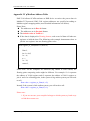
Appendix IV:Modbus Address Table
PMC-5141 allows SCADA software or HMI device to retrieve the power data via
Modbus TCP protocol. PMC-5141 register addresses are specified according to
Modbus register mapping tables (more detailed information will follow).
Please Note:
The addresses are in Base 0 format
The addresses are in Decimal format
The default value of NetID is 1.
If the data is displayed in Floating format, each record of data will take two
registers to hold the data. The following code example demonstrates how to
join the two registers into one floating point value.
float register_to_float(short r1, short r2)
{
float f;
int *a = &f;
*a = r1;
a++;
*a = r2;
return f;
}
Please note: for the compilers are different (big endian or little endian) the
floating point composing order might be different. For example: if r1 represent
the address of 30100 register and r2 represent the address of 30101 register, to
join r1 and r2 to a floating point, in the system is big endian system you will need
to call:
float value = register_to_float(r1, r2);
Instead, if the system is little endian system, you will need to call:
float value = register_to_float(r2, r1);
Please note:
1. If you are not sure your compiler belongs to which system, try both ways
to find the accurate one.
http://www.icpdas.com
51
ICP DAS PMC-5141 User Manual
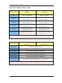
PMC-5141 Modbus Address Table
0xxxx
1xxxx
(Coil Output)
(Discrete Input)
0-99
XW-107 DO value
XW-107 DI value
100-199
Power Meter DO value
(RS-485 address=1)
Power Meter DI value
(RS-485 address=1)
200-299
Power Meter DO value
(RS-485 address=2)
Power Meter DI value
(RS-485 address=2)
300-399
Power Meter DO value
(RS-485 address=3)
Power Meter DI value
(RS-485 address=3)
400-499
Power Meter DO value
(RS-485 address=4)
Power Meter DI value
(RS-485 address=4)
100+(N-1)*100~
99+N*100
Power Meter DO value
(RS-485 address=N, N<=64)
Power Meter DI value
(RS-485 address=N, N<=64)
Modbus Address
The RS-485 address setting for PM-213x/PM-311x power meter is between 1~64, but
the PMC-5141 only can connect with up to 16 ICP DAS power meters at one time.
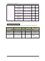
Modbus Address
3xxxx
4xxxx
(Input Register)
(Holding Register)
0000~0099
PMC-5141System Data
0100~0299
Power Meter Data (RS-485 address=1)
0300~0499
Power Meter Data (RS-485 address=2)
0500~0699
Power Meter Data (RS-485 address=3)
0700~0899
Power Meter Data (RS-485 address=4)
0900~1099
Power Meter Data (RS-485 address=5)
100+(N-1)*200~
99+N*200
Power Meter Data (RS-485 address=N, N<=64)
The RS-485 address setting for PM-213x/PM-311x power meter is between 1~64, but
the PMC-5141 only can connect with up to 16 ICP DAS power meters at one time.
http://www.icpdas.com
52
ICP DAS PMC-5141 User Manual
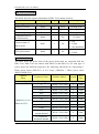
PMC-5141 System Data
This block stores the system information of PMC-5141, shown as below:
Parameter Name
Modbus Address Length
Data Type
Range
Input Register, Unit : Register(16 Bits)
Firmware Version
30000
2
Float
Floating Point
Free Disk Space
30002
2
Float
Floating Point
Contract Capacity
30004
2
Float
Floating Point
30006
1
Int
15/30/60
Calculation Interval
for Demand(kW)
Connect status of
Power meter
30007
1
Int
1:OK
0:Failed
-1:Not Initialized
FTP Upload status
30008
1
Int
1:OK
0:Failed
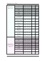
Power Meter Data
The block stores the power data of the power meters that are connected with the
PMC-5141. PMC-5141 can connect with PM-213x and PM-311x. For each type of
power meter has different properties, the following sub-blocks are representing 3
Phase power meter (PM-2133) or 4/2 Loops (Channels) 1 Phase power meter
(PM-2134/PM-3112).
Channel/
Phase
Parameter Name
Modbus Address
Input Register, Unit :Register(16 Bits)
Channel1(2134,3112)
/Phase A(2133)
http://www.icpdas.com
Length
Data
Type
N: RS-485 Address
V
30100 + (N-1)*200
2
Float
I
30102 + (N-1)*200
2
Float
kW
30104 + (N-1)*200
2
Float
kvar
30106 + (N-1)*200
2
Float
kVA
30108 + (N-1)*200
2
Float
PF
30110 + (N-1)*200
2
Float
kWh
30112 + (N-1)*200
2
Float
kvarh
30114 + (N-1)*200
2
Float
kVAh
30116 + (N-1)*200
2
Float
15/30/60 mins
current demand
30118 + (N-1)*200
2
Float
15/30/60 mins
Predicted demand
30120 + (N-1)*200
2
Float
53
ICP DAS PMC-5141 User Manual
Max. demand
(Hourly)
30122 + (N-1)*200
2
Float
Max. demand
(Daily)
30124 + (N-1)*200
2
Float
Max. demand
(Monthly)
30126 + (N-1)*200
2
Float
Daily Tot.
Electricity
30128 + (N-1)*200
2
Float
30130 + (N-1)*200
2
Float
Yearly Tot.
Electricity
30132 + (N-1)*200
2
Float
V
30134 + (N-1)*200
2
Float
I
30136 + (N-1)*200
2
Float
kW
30138 + (N-1)*200
2
Float
kvar
30140 + (N-1)*200
2
Float
kVA
30142 + (N-1)*200
2
Float
PF
30144 + (N-1)*200
2
Float
kWh
30146 + (N-1)*200
2
Float
kvarh
30148 + (N-1)*200
2
Float
kVAh
30150 + (N-1)*200
2
Float
15/30/60 mins
current demand
30152 + (N-1)*200
2
Float
15/30/60 mins
Predicted demand
30154 + (N-1)*200
2
Float
Max. demand
(Hourly)
30156 + (N-1)*200
2
Float
Max. demand
(Daily)
30158 + (N-1)*200
2
Float
Max. demand
(Monthly)
30160 + (N-1)*200
2
Float
Daily Tot.
Electricity
30162 + (N-1)*200
2
Float
Monthly Tot.
Electricity
30164 + (N-1)*200
2
Float
30166 + (N-1)*200
2
Float
30168 + (N-1)*200
2
Float
Monthly Tot.
Electricity
Channel2(2134,3112)
/Phase B(2133)
Yearly Tot.
Electricity
V
http://www.icpdas.com
54
ICP DAS PMC-5141 User Manual
Channel3(2134)
/Phase C(2133)
I
30170 + (N-1)*200
2
Float
kW
30172 + (N-1)*200
2
Float
kvar
30174 + (N-1)*200
2
Float
kVA
30176 + (N-1)*200
2
Float
PF
30178 + (N-1)*200
2
Float
kWh
30180 + (N-1)*200
2
Float
kvarh
30182 + (N-1)*200
2
Float
kVAh
30184 + (N-1)*200
2
Float
30186 + (N-1)*200
2
Float
15/30/60 mins
Predicted demand
30188 + (N-1)*200
2
Float
Max. demand
(Hourly)
30190 + (N-1)*200
2
Float
Max. demand
(Daily)
30192 + (N-1)*200
2
Float
Max. demand
(Monthly)
30194 + (N-1)*200
2
Float
Daily Tot.
Electricity
30196 + (N-1)*200
2
Float
Monthly Tot.
Electricity
30198 + (N-1)*200
2
Float
Yearly Tot.
Electricity
30200 + (N-1)*200
2
Float
V
30202 + (N-1)*200
2
Float
I
30204 + (N-1)*200
2
Float
kW
30206 + (N-1)*200
2
Float
kvar
30208 + (N-1)*200
2
Float
kVA
30210 + (N-1)*200
2
Float
PF
30212 + (N-1)*200
2
Float
kWh
30214 + (N-1)*200
2
Float
kvarh
30216 + (N-1)*200
2
Float
kVAh
30218 + (N-1)*200
2
Float
15/30/60 mins
current demand
30220 + (N-1)*200
2
Float
30222 + (N-1)*200
2
Float
15/30/60 mins
current demand
Channel4(2134)
/Total or Average
value(2133)
15/30/60 mins
Predicted demand
http://www.icpdas.com
55
ICP DAS PMC-5141 User Manual
Max. demand
(Hourly)
30224 + (N-1)*200
2
Float
Max. demand
(Daily)
30226 + (N-1)*200
2
Float
Max. demand
(Monthly)
30228 + (N-1)*200
2
Float
Daily Tot.
Electricity
30230 + (N-1)*200
2
Float
30232 + (N-1)*200
2
Float
30234 + (N-1)*200
2
Float
Monthly Tot.
Electricity
Yearly Tot.
Electricity
Other Information of Power Meter
This block stores other information of power meters which connect with PMC-5141.
Parameter Name
Modbus Address
Length
Data Type
Range
Input Register, Unit : Register(16 Bits) N: RS-485 Address
PT Value
30290 + (N-1)*200
2
Float
0.01~655.35
CT Value
30292 + (N-1)*200
1
Unsigned Int
1~65535
Power Meter Type 30293 + (N-1)*200
1
Int
2133/2134/3112
Int
1:OK
0:Failed
-1:Not Initialized
Error Code
http://www.icpdas.com
30294 + (N-1)*200
1
56


![Hockey Canada Registry User Manual [Complete]](http://vs1.manualzilla.com/store/data/006861334_1-f3aefff99f86c1666505c30ddd463ccc-150x150.png)