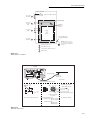
1
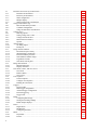
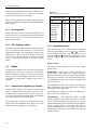
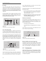
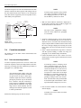
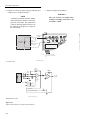
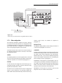
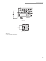
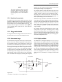
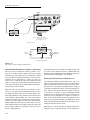
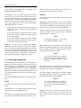
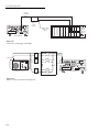
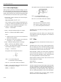
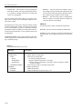
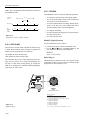
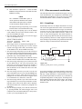
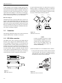
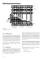
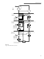
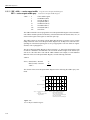
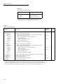
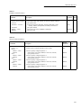
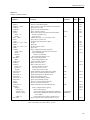
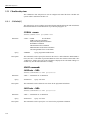
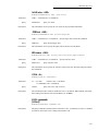
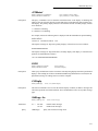
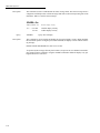
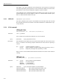
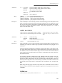
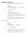
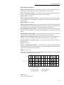
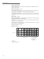
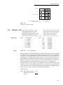
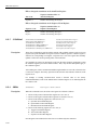
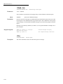
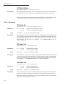
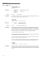
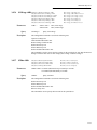
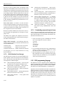
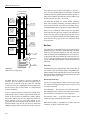
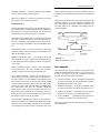
Front Panel Operation
(SOURCE V2) is then applied and, after the next delay (DELAY 2), a second resistance measurement is made. The
Model 6517A then automatically calculates the voltage coefficient and stores it in the buffer. This test is selected and con-
figured from the CONFigure SEQUENCE menu (DEVCHAR; RESISTOR). See paragraph 2.14.2 for details.
6517A
WARNING:NO INTERNAL OPERATOR SERVICABLE PARTS,SERVICE BY QUALIFIED PERSONNEL ONLY.
HI
7078-TRX Cable
LO
INPUT
HI
V SOURCE
PREAMP OUT COMMON
!
250V PEAK
250V PEAK
LINE RATING
LINE FU
SLOWBL
90-134VAC
180-250VAC
50, 60, 400HZ
55VA MAX
1/2A, 25
IEEE-488
(CHANGE IEEE ADDRESS
WITH FRONT PANEL MENU)
Shield
Cable
IN
OUT
TRIGGER
LINK
Center
Conductor
Insulator
CAUTION:FOR CONTINUED PROTECTION AGAINST FIRE HAZARD,REPLACE FUSE WITH SAME TYPE AND RATING.
Note: Ammeter LO internally
connected to V-Source
LO (See Paragraph 2.9.1).
A) Connections
6517A
V-Source
+ HI
Cable
Resistance
- LO
HI
A
6517A
Ammeter
LO
B) Equivalent Circuit
Figure 2-50
Connections; cable insulation resistance test
2-63