1
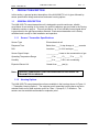
HLM-2000-TX Gas Transmitter User Manual Technical Support Continental North America Toll Free 1-(800) 387-9487 Ph: +1 (905) 829-2418 Fx: +1 (905) 829-4701 A Product of Arjay Engineering Ltd. Oakville, Ontario, Canada www.ArjayEng.com www.EnmetGasDetection.com Model: HLM-2000-TX HLM-2000-TX UM11.doc Rev: 1.1 TABLE OF CONTENTS Section Title Page WARRANTY .................................................................................................................................2 LIABILITY .....................................................................................................................................2 MODIFICATIONS AND SUBSTITUTIONS ..................................................................................2 PRODUCT RETURN ...................................................................................................................2 PRODUCT INFORMATION .........................................................................................................3 1 PRODUCT DESCRIPTION.............................................................................................4 1.1 2 3 4 5 GENERAL DESCRIPTION ................................................................................4 1.1.1 Sensor Specifications ..........................................................................4 1.1.2 Housing Options ..................................................................................4 INSTALLATION...............................................................................................................6 2.1 LOCATION AND MOUNTING ...........................................................................6 2.2 CABLE SELECTION AND WIRING ...................................................................7 2.2.1 Transmitter to Monitor Wiring ..............................................................8 2.2.2 Interfacing to computer, datalogger, or non-Arjay monitor..................9 OPERATION AND CALIBRATION .................................................................................11 3.1 OPERATION ......................................................................................................11 3.2 CALIBRATION ...................................................................................................11 3.2.1 Equipment required .............................................................................12 3.2.2 Transmitter calibration/verification set-up procedure ..........................12 3.2.3 Adjustments .........................................................................................12 PREVENTATIVE MAINTENANCE .................................................................................14 4.1 GENERAL ..........................................................................................................14 4.2 VERIFICATION OF OPERATION......................................................................14 4.3 SENSOR REPLACEMENT ................................................................................14 ADDENDUM TO HLM-2000-TX (FOR OXYGEN ONLY)...............................................16 Figure 1.1 – “Transmitter Housing Options” ................................................................................5 Figure 2.1 - "Mounting the Sensor/Transmitter Unit" ...................................................................6 Figure 2.2 - "Cable Selection Graph" ...........................................................................................7 Figure 2.3 - " Transmitter to Monitor Wiring Layout"....................................................................9 Figure 2.4 - "Interfacing to a Computer, Datalogger, or Non-Arjay Monitor" ...............................10 Figure 3.1- "Calibration/Verification set-up Procedure" ...............................................................13 Figure 4.1- "Sensor Replacement and Wiring Procedure" ..........................................................15 Figure 5.1- "Transmitter with oxygen sensor wiring layout" .........................................................16 1 Model: HLM-2000-TX HLM-2000-TX UM11.doc Rev: 1.1 WARRANTY The HLM-2000-TX transmitters are warranted against defects in material and workmanship for a period of two years from date of delivery (for sensor, see 1.1.1 Sensor / Transmitter Specifications). During the warranty period, Arjay Engineering will repair or replace components that prove to be defective in the opinion of Arjay. We are not liable for auxiliary interfaced equipment, or consequential damage. This warranty shall not apply to any product, which has been modified in any way, which has been repaired by any other party other than a qualified technician or authorized Arjay representative, or when such failure is due to misuse or conditions of use. LIABILITY All Arjay products must be installed and maintained according to instructions. Only qualified technicians should install and maintain the equipment. Arjay shall have no liability arising from auxiliary interfaced equipment, for consequential damage, or the installation and operation of this equipment. Arjay shall have no liability for labour or freight costs, or any other costs or charges in excess of the amount of the invoice for the products. THIS WARRANTY IS IN LIEU OF ALL OTHER WARRANTIES, EXPRESSED OR IMPLIED, AND SPECIFICALLY THE WARRANTIES OF MERCHANTABILITY AND FITNESS FOR A PARTICULAR PURPOSE. THERE ARE NO WARRANTIES THAT EXTEND BEYOND THE DESCRIPTION ON THE FACE THEREOF. MODIFICATIONS AND SUBSTITUTIONS Due to an ongoing development program, Arjay reserves the right to substitute components and change specifications at any time without incurring any obligations. PRODUCT RETURN All products returned for warranty service will be by prepaid freight and they will only be accepted with an R.M.A number issued by Arjay. All products returned to the client will be freight collect. WARNING USING ELECTRICALLY OPERATED EQUIPMENT NEAR GASOLINE, OR GASOLINE VAPOURS MAY RESULT IN FIRE OR EXPLOSION, CAUSING PERSONAL INJURY AND PROPERTY DAMAGE. CHECK TO ASSURE THE WORKING AREA IS FREE FROM SUCH HAZARDS, AND USE PROPER PRECAUTIONS. 2 Model: HLM-2000-TX HLM-2000-TX UM11.doc Rev: 1.1 PRODUCT INFORMATION Sensor/Transmitter Sensor/Transmitter Unit Order Number __________________ Transmitter Part Number __________________ Transmitter Serial Number __________________ Sensor Part Number __________________ Sensor Serial Number __________________ Power Supply Requirement 12 to 30 VDC @ 20 mA Sensor Warranty __________________ Factory Calibration Gas Type __________________ Zero Gas, at 4 mA Signal __________________ Gas Concentration at 20 mA Signal __________________ NOTE: ALL ARJAY MONITORING SYSTEMS MUST BE INSTALLED AND MAINTAINED ACCORDING TO INSTRUCTIONS, TO ENSURE PROPER OPERATION. ONLY QUALIFIED TECHNICIANS SHOULD INSTALL AND MAINTAIN THE EQUIPMENT. 3 Model: HLM-2000-TX 1 HLM-2000-TX UM11.doc Rev: 1.1 PRODUCT DESCRIPTION In this section, a general product description of the HLM-2000-TX unit is given followed by sensor specification listings and various enclosure housing options 1.1 GENERAL DESCRIPTION The HLM-2000-TX sensor/transmitter unit is designed to provide continuous, reliable surveillance of surrounding air for traces of a specific hazardous gas (es) listed in the Factory Calibration section on page vi. This unit provides a 4 to 20 mA variable current signal which is proportional to the gas concentration detected. Each sensor/transmitter unit is factory calibrated and is ready for field installation and operation. 1.1.1 Sensor / Transmitter Specifications Sensor Type Electrochemical cell Response Time Better than ____% step change in ____ seconds Drift Less than ____% of full scale per ____ Sensor Signal Output ____________ Linear to the concentration of gas Operating Temperature Range _____C to _____C (_____F to _____F) Humidity _____% to _____% RH, non-condensing Expected Sensor Life Greater than ____ year(s) Note: 1.1.2 TURN OFF POWER SUPPLY BEFORE REMOVING OR REPLACING THE TRANSMITTER OR SENSOR. Housing Options The HLM-2000-TX sensor/transmitter units are available in the housings shown in Figure 1.1 – “Transmitter Housing Options”. The explosion proof transmitter housing has a corrosion resistant finish and is rated explosion proof for Class 1, Groups B, C, D locations. The sensors are also available as standard or explosion proof. 4 Model: HLM-2000-TX HLM-2000-TX UM11.doc Rev: 1.1 PVC HOUSING: Rectangular PVC with cover plate held by four screws. Not for use in combustible areas and not weather proof. - PVC HOUSING: Width: Height: Length: Hub Size: 2.9” 2.25” 6” ¾” NPT EXPLOSION PROOF HOUSING: Round housings with screw-on covers. Weatherproof and explosion proof. (see rating listed in section 0) B C D HOUSING Width: Height: Length: Hub Size: 4.9” 4.7” 4.8” ¾” NPT Figure 1.1 – “Transmitter Housing Options” 5 + Model: HLM-2000-TX 2 HLM-2000-TX UM11.doc Rev: 1.1 INSTALLATION This section discusses topics relating to the proper installation of the HLM-2000-TX unit. 2.1 LOCATION AND MOUNTING Mount the sensor/transmitter unit on a solid, non-vibrating surface or structure in an area where the local concentration of gas is unaffected by the presence of ventilation systems and away from sources of interference gases. NOTE: MOUNTING ARRANGEMENT OF THE HOUSING DEPENDS ON LOCATION AND MOUNTING SURFACE. MOUNTING HARDWARE IS NOT SUPPLIED. Figure 2.1 - "Mounting the Sensor/Transmitter Unit" 6 HLM-2000-TX UM11.doc Model: HLM-2000-TX 2.2 Rev: 1.1 CABLE SELECTION AND WIRING Connection should be made using 2-conductor, shielded cable. For best signal transmission and maximum noise rejection, run the cable through steel conduit (cable must be grounded at the monitor or power supply). Supply voltage can be measured at the transmitter (-,+) connections at the supply source. For basic cable selection between the source and transmitter, using a 250 ohm load resistance, use Table 0-1 - "Cable Selection Guide". Table 0-1 - "Cable Selection Guide" WIRE GAUGE AWG 22 20 18 16 MAXIMUM DISTANCE IN FEET AND (metres) @12 VDC 1000 (305) 1500 (457) 2500 (762) 3800 (1158) @ 24 VDC 15000 (4572) 23000 (7010) 38000 (11582) 57000 (17373) For applications not covered by the above chart, an example is shown below for selecting the right cable, using the graph in Figure 2.2 - "Cable Selection Graph" and the following formulas. NOTE: Linear Loop Resistance including load resistance (ohms) SOME NON-ARJAY EQUIPMENT MAY HAVE THE LOAD RESISTANCE BUILT IN. 1200 1100 1000 900 800 700 600 500 400 300 200 100 0 MR Safe Region LR 6 8 10 12 14 16 18 20 22 24 26 28 30 Supply Voltage (volts) Figure 2.2 - "Cable Selection Graph" 7 Model: HLM-2000-TX HLM-2000-TX UM11.doc Rev: 1.1 Example: Refer to Figure 2.2 - "Cable Selection Graph" Known Data: Obtained from measurements, ratings or specifications. Power Supply ........................................................... 17 VDC Load Resistance ....................................................... 180 ohms Wire Gauge .............................................................. 20 AWG Cable Length / 1 Ohm resistance ............................. 43.6 ft (13.3 m) typical Calculations on the Graph: Using the power supply voltage as a reference. Maximum Resistance ............................................... MR Load Resistance ....................................................... LR Formula 1: To determine remaining safe loop resistance. Maximum Resistance 518 Ohms Load Resistance - 180 Ohms Remaining Resistance = 338 Ohms Formula 2: To determine maximum safe cable length allowed. Remaining Resistance 338 Ohms Cable Length (for 1 Ohm) x 43.6 feet Maximum Safe Cable Length = 14 736 feet NOTE: IF MAXIMUM SAFE CABLE LENGTH IS INSUFFICIENT, INCREASE THE POWER SUPPLY VOLTAGE AND/OR REDUCE THE LOAD RESISTANCE. 2.2.1 Transmitter to Monitor Wiring The transmitter output (-,+) terminals connect to the (SIG,+) terminals on a channel terminal block of the monitor (one transmitter per channel), as shown in Figure 2.3 - " Transmitter to Monitor Wiring Layout". Each transmitter MUST BE CONNECTED TO ITS CORRESPONDING CHANNEL to retain factory calibration of the trip points. 8 Model: HLM-2000-TX HLM-2000-TX UM11.doc Rev: 1.1 Figure 2.3 - " Transmitter to Monitor Wiring Layout" 2.2.2 Interfacing to computer, datalogger, or non-Arjay monitor All Arjay sensor/transmitters can be connected to computers or dataloggers through analog-todigital converters, or to non-Arjay monitors. The transmitter output (-,+) terminals connect to a filtered 12 to 30 VDC power supply, through field wiring. (see Figure 2.4 - "Interfacing to a Computer, Datalogger, or Non-Arjay Monitor") The signal output from the transmitter is a 4 to 20 milliamp DC current. This signal can be measured or recorded anywhere in the supply loop if required. Alternatively, if a voltage measurement is needed a resistor can be connected (see Figure 2.4 - "Interfacing to a Computer, Datalogger, or Non-Arjay Monitor"), between the transmitter’s negative (-) output terminal and the negative or common (-) of the power supply. 9 Model: HLM-2000-TX HLM-2000-TX UM11.doc Rev: 1.1 Figure 2.4 - "Interfacing to a Computer, Datalogger, or Non-Arjay Monitor" 10 Model: HLM-2000-TX 3 HLM-2000-TX UM11.doc Rev: 1.1 OPERATION AND CALIBRATION This section covers instructions for the proper operation and calibration of the HLM-2000-TX units. The operation principles are described in further detail, followed by different types of periodic adjustments that might be required throughout the lifetime of the equipment. 3.1 OPERATION The HLM-2000-TX sensor/transmitter unit is factory calibrated for the gas listed in Product Information (pg. vi) at the beginning of this manual. The unit should not need recalibration when first installed and powered-up, but a test for correct operation is recommended after a stabilization period of 10 minutes. In general, after the stabilization period, the transmitter should be sending (in zero gas) a signal of approximately 4 mA to the monitor or controller. However, there are a few situations where a slightly higher or lower than normal signal may be noticed. In many facilities there are residual background gases (including the gas being detected) in the air at all times. These can cause for minor signal variations include extremes in temperature. In the case of large signal variations (in a clean air environment), check for an installation problem or the possibility of an interference gas being present. Although the electrochemical sensors are very selective, there are some interference gases which can cause a response from the sensor. These gases are listed on the detailed Specification sheet pertaining to the sensor in use. 3.2 CALIBRATION The transmitter is equipped with a remote calibration feature allowing one-man calibration at the transmitter location. The transmitter output is measured using a plug-in type “Remote Calibration Lead” (p/n 2900-01) designed to be adaptable to most multi-meters. Zero and Span adjustments are made at the transmitter. Recalibration is necessary when replacing the sensor. Verification of calibration should be done at least once every 6 months for safety reasons and for highly demanding applications, monthly verification is recommended. Factory on-site calibration services, customer training, and/or calibration kits can be provided. Specify the sensor/transmitter type and gas when requesting any of the above. CAUTION: ONLY QUALIFIED PERSONNEL SHOULD PERFORM THE ACTUAL CALIBRATION. USERS ARE ADVISED TO CONSULT ARJAY ENGINEERING AS TO THE RECOMMENDED CALIBRATION GAS CONCENTRATION FOR THE APPLICATION, OR OTHER QUESTIONS For some exotic gases, calibration standards needed for field calibration are not readily available. Arjay Engineering offers the following options: 1. pre-calibrated sensor/transmitters to replace expired units 2. factory installation and calibration of new sensors in returned transmitters 3. replacement sensors supplied with a pre-calibrated electrical output For all above options, please contact the factory for details. 11 Model: HLM-2000-TX 3.2.1 HLM-2000-TX UM11.doc Equipment required 1. Digital Multi-meter 2. “Remote Calibration Lead” provided with the transmitter 3. “Trimmer Adjustment Tool” or miniature screwdriver 4. Calibration gas(es) 3.2.2 Rev: 1.1 Transmitter calibration/verification set-up procedure NOTE: WHEN APPLYING GAS, A FLOW RATE OF 0.5 TO 1 LITRE PER MINUTE IS RECOMMENDED. The calibration procedure may cause the monitoring equipment to give a false alarm, therefore appropriate precautions should be taken. Instructions on introducing the gas sample are included with the calibration kit or available separately (depending on type of gas or application). Refer to Figure 3.1- "Calibration/Verification set-up Procedure" for the following procedure. 1. Remove cover from transmitter housing. 2. Plug in standard test leads fully into jacks on multi-meter. 3. Switch-ON multi-meter and select DC volts range to read greater than 1.00 VDC. 4. Apply a Zero gas sample, or with the sensor in clean air, adjust the Zero trimmer for a stabilized reading of 0.00 VDC measured at the test points. 5. Unplug test leads and connect “Remote Calibration Lead” to multi-meter. The BLACK lead to negative or common (-) and the RED lead to positive (+) 6. Insert plug end of “Remote Calibration Lead” fully into CAL jack on the transmitter. 7. Select DC milliamp range on the multi-meter to read greater than 20 mA full scale. 8. If reading is not 4.00 mA,, adjust trimmer accordingly. 9. Apply a Span gas sample. The span gas sample need not be the full scale concentration but could be a fraction of this. Since the transmitter output range is 4 to 20 mA, a full scale concentration should register 20 mA after a few moments exposure. A half scale concentration, accordingly, should provide 12 mA and so on. 10. Alternately, the integral digital display readout can be used to make the adjustments in steps 4 and 9 above. 3.2.3 Adjustments For full recalibration adjustments, follow the Set-Up Procedure steps 1 to 9 inclusive. There are two adjustments to be made for periodic recalibration, Zero and Span. Zero: When there is no gas present, the transmitter signal output should be 4.00 mA. This is obtained by adjusting the Zero trimmer on the transmitter. Alternately, set the integral display to read “zero” using the zero trimmer with no gas present. 12 Model: HLM-2000-TX HLM-2000-TX UM11.doc Rev: 1.1 Span: When the sensor is exposed to the calibration gas sample, adjust the span trimmer on the transmitter to set the output current proportional to the gas concentration applied, or the appropriate reading on the display. Figure 3.1- "Calibration/Verification set-up Procedure" 13 Model: HLM-2000-TX 4 HLM-2000-TX UM11.doc Rev: 1.1 PREVENTATIVE MAINTENANCE This section covers topics related to the maintenance of the HLM-2000-TX units. A general description of maintenance to be carried out is followed by a verification of operation and then details about the sensor replacement. 4.1 GENERAL The sensor/transmitter unit should be brushed or wiped clean once a year or more, of any dust or dirt that settles on it, depending on the accumulation. The unit SHOULD NOT be submerged or placed under conditions where water or other liquids would be able to enter the transmitter. 4.2 VERIFICATION OF OPERATION To verify the operation of the sensor/transmitter unit, make sure that it is still responding to gas. This test should be performed every 2 months, but for more demanding applications, verification should be performed on a weekly basis. 4.3 SENSOR REPLACEMENT CAUTION: TURN OFF POWER SUPPLY BEFORE ATTEMPTING THE FOLLOWING Signal from the sensor will be greatly reduced when its replacement is required. The sensor should be replaced when it no longer responds to the presence of gas or has an unstable zero signal. When the sensor needs replacing, re-order the Part Number listed in Product Information (pg.vi). When sensors are shipped, some sensor leads may be shorted together. This is done to provide rapid stabilization of the sensor signal after installation. To wire the sensor for correct operation, first separate (cut apart) the shorted leads, if any, then connect the RED lead to the “R” terminal, then BLACK to “S” and the YELLOW to “C” of the sensor terminal block on the transmitter. See Figure 4.1- "Sensor Replacement and Wiring Procedure" for sensor replacement and wiring procedure. NOTE: ALLOW 10 MINUTES FOR THE NEW SENSOR TO STABLILIZE BEFORE RECALIBRATION, THEN FOLLOW THE INSTRUCTIONS IN CALIBRATION (SECTION 3.2) OF THIS MANUAL. 14 Model: HLM-2000-TX HLM-2000-TX UM11.doc Figure 4.1- "Sensor Replacement and Wiring Procedure" 15 Rev: 1.1 Model: HLM-2000-TX 5 HLM-2000-TX UM11.doc Rev: 1.1 ADDENDUM TO HLM-2000-TX (FOR OXYGEN ONLY) This HLM-2000-TX ( 2-wire sensor / transmitter with external electro-chemical sensors ) has been modified and the following information replaces the terminal block & sensor wiring of Figures 2-3, 2-4, 3-1 & 4-1. The sensor / transmitter shows that the three wires changed to two wires for OXYGEN SENSOR ONLY. Terminal block & sensor wiring configuration are as shown below: Figure 5.1- "Transmitter with oxygen sensor wiring layout" 16 MAINTENANCE AND CALIBRATION Your ARJAY / ENMET gas detector is the state of the art in gas detection, but like any other part of your ventilation system, it requires periodic maintenance and calibration. There are various sensor technologies that may be used in your Arjay gas monitor; including solid state MOS, Electrochemical, Infrared and Pellister Pair (Hot wire). These have a normal operating life of 3 to 5 years under ambient conditions. You should consider a preventive maintenance schedule whereby you test your system on a periodic basis to ensure its proper calibration and operation. For solid state (MOS) sensors, we recommend calibration every 3 to 4 months for a typical garage application. For Electrochemical sensors, we recommend calibration every 6 months for a typical garage application. Pellister Pair we recommend every 3 to 4 months and Infrared we recommend every 6 months. For applications that are more sensitive, or where internal policies exist, a higher frequency of calibration may be required. This is a simple procedure which will indicate any problems with your system. A test and calibration kit may be purchased from ARJAY ENGINEERING for this purpose. Parts are also readily available from our facility. MAINTENANCE CONTRACT Alternatively you may wish to consider a Maintenance Contract with ARJAY ENGINEERING whereby one of our service technicians comes to your site and checks out the unit for proper calibration and operation on a regularly scheduled basis. This is done on a flat per annum fee. All parts are extra. Typical target gases are included, however, exotic or specialty gases may have a surcharge. If you wish us to quote a Maintenance Contract fill in the section below and return to our office. COMPANY: ADDRESS: CONTACT PERSON: PHONE: FAX: EMAIL: MODEL AND SERIAL NO. OF GAS DETECTOR: Fax to address below or e-mail to [email protected] ARJAY ENGINEERING LTD 2851 Brighton Rd Oakville, Ontario, Canada L6H 6C9 Telephone: +1 (905)-829-2418 Telefax: +1 (905)-829-4701 N. America Toll: (800)-387-9487 Internet: www.arjayEng.com E-Mail: [email protected] ARJAY ENGINEERING LTD. GUARANTEE We hereby guarantee this instrument to be free from defects in workmanship and materials, and if found defective in workmanship or materials, upon being returned to our factory, prepaid, within one year from date of purchase, it will be repaired or replaced at factory without charge. However, if upon being returned and after inspection, there is evidence that the instrument has been subjected to tampering, careless handling, improper or faulty application or installation, the above guarantee shall not be applicable, and we shall have the right in any such case to make a charge to cover the cost of repairs, servicing and transportation expense. The undersigned assumes and shall have no liability for consequential damages resulting from the use or misuse of the instrument. The foregoing guarantee is in lieu of all other guarantees or warranties, expressed or implied, and all other obligations or liabilities, contractual or otherwise, either to the original purchaser of said instrument, or to any other person whomever. BY: ARJAY ENGINEERING LTD. For service, call ARJAY Engineering Ltd. directly: Canada (905) 829-2418 North American Toll Free: 1-800-387-9487 Fax: (905) 829-4701 Internet: www.arjayeng.com E-mail: [email protected] ARJAY ENGINEERING LTD 2851 Brighton Rd Oakville, Ontario, Canada L6H 6C9 Telephone: +1 (905)-829-2418 Telefax: +1 (905)-829-4701 N. America Toll: (800)-387-9487 Internet: www.arjayEng.com E-Mail: [email protected]