1
UNIVERSITY OF NAIROBI
SCHOOL OF COMPUTING AND INFORMATICS
MASTER OF SCINCE IN COMPUTER SCIENCE
MULTI-AGENT BASED REALTIME ELECTRIC TRANSFORMERS
MONITORING SYSTEM
BY
BORE DAVID KIBET KORIR
P58/77067/2009
October 2014
SUPERVISOR
MR. ERIC AYIENGA
Submitted in partial fulfillment of the requirements of
Master of Science in Computer Science
Page |i
Multi-agent based Realtime electric transformers Monitoring System
DECLARATION
I, Bore David Kibet Korir hereby declare that this project is my original work submitted
to Nairobi University in partial fulfillment of requirements of Master of Science in
Computer Science and has not been presented for a degree in any other university
SIGN…………………………………….
Name: BORE DAVID KIBET KORIR
DATE………………………………………
Registration No: P58/77067/2009
This project has been submitted in partial fulfillment of requirements of Master of Science
in Computer Science of the University of Nairobi with my approval as University
supervisor.
SIGN ………………………………….. DATE…………………………………………
Name: MR. ERIC AYIENGA
School of Computing and Informatics, University of Nairobi
P a g e | ii
Multi-agent based Realtime electric transformers Monitoring System
DEDICATION
To
My family, my supervisor, my lecturers, University of Nairobi as whole and colleagues, I
wish to appreciate your valuable support and contribution you accorded me throughout the
whole process this project initiation till completion.
Thank you and May God the almighty bless you all.
P a g e | iii
Multi-agent based Realtime electric transformers Monitoring System
ACKNOWLEDGEMENT
I wish to thank God for having given me strength and guidance in this project.
Special thanks to my supervisor and University of Nairobi staff especially those at school
of computing and informatics for their great support and good relation throughout the time
I was a student of this university.
Contribution from friends and colleagues towards this project is highly appreciated
The Kenya Power and Lighting Company played a key role in this project by allowing me
access to information and data that was valuable and useful in this project from start to
completion.
Lastly I wish to acknowledge my parents, Late John Bore and Late Christine Bore for
bringing me up to this far both educationally and morally, all my siblings especially Mary
Kirui for her immense support during my school time, my dear wife Emmy, my children
Brian, Ian and Allan. Thank you all.
P a g e | iv
Multi-agent based Realtime electric transformers Monitoring System
TABLE OF CONTENTS
DECLARATION.................................................................................................................. ii DEDICATION..................................................................................................................... iii GLOSSARY OF TERMS................................................................................................. viii LIST OF TABLES .............................................................................................................. ix LIST OF FIGURES ............................................................................................................. x ABSTRACT........................................................................................................................ xii CHAPTER ONE: INTRODUCTION ................................................................................ 1 1.1 Background ............................................................................................................... 1 1.2 Real-time monitoring of transformers....................................................................... 3 1.3 The Problem Statement ............................................................................................. 4 1.4 Research Question..................................................................................................... 5 1.5 System development Objectives ............................................................................... 5 1.6 Research objectives................................................................................................... 6 1.7 The Significance and Justification of the Study........................................................ 6 1.8 The Scope and Limitations of the Study ................................................................... 7 1.9 Own Contribution...................................................................................................... 8 CHAPTER TWO: THE LITERATURE REVIEW ......................................................... 9 2.1 Overview ................................................................................................................... 9 2.2 General GSM Architecture ..................................................................................... 11 2.3 GSM alarm system.................................................................................................. 12 2.4 GSM alarm receiver ................................................................................................ 13 2.5 Detectors ................................................................................................................. 14 2.6 Agents. .................................................................................................................... 15 2.7 Agent Architectures ................................................................................................ 15 2.8 Modeling of agent-based systems ........................................................................... 17 2.9 Application of Multi-agents Systems...................................................................... 17 2.10 Control Centre......................................................................................................... 17 2.11 SMS and Email security.......................................................................................... 18 Page |v
Multi-agent based Realtime electric transformers Monitoring System
2.12 Electric transformers ............................................................................................... 18 2.13 Overall System Architecture ................................................................................... 19 3. Previous works ........................................................................................................ 19 4. Conceptual Model ................................................................................................... 21 CHAPTER THREE: THE METHODOLOGY .............................................................. 23 3.1 System design methodology ................................................................................... 23 3.2 System Design scope............................................................................................... 23 3.3 Frameworks for designing and Specification of MAS........................................... 23 3.3.1 Requirement Model ........................................................................................... 25 3.3.2 Agent Society Model......................................................................................... 28 3.3.3 Agent Implementation Model............................................................................ 30 3.3.4 Code Model ....................................................................................................... 30 3.3.5 Deployment Model............................................................................................ 30 3.4 Selected Programming Language ........................................................................... 31 3.5 Database .................................................................................................................. 31 3.6 GSM Modem........................................................................................................... 32 CHAPTER FOUR: SYSTEM ANALYSIS AND DESIGN........................................... 33 Feasibility study............................................................................................................... 33 Planning ........................................................................................................................... 35 Analysis ........................................................................................................................... 35 Design .............................................................................................................................. 35 System Design Flowchart ................................................................................................ 36 CHAPTER FIVE: ANALYSIS OF RESULTS ............................................................. 37 CHAPTER SIX: SYSTEM TESTING AND EVALUATION ....................................... 42 Sensor Alert Processing................................................................................................... 43 Vandalism drill test.......................................................................................................... 44 Simulation method........................................................................................................... 45 CONCLUSION .................................................................................................................. 49 REFERENCES................................................................................................................... 50 APPENDICES .................................................................................................................... 53 P a g e | vi
Multi-agent based Realtime electric transformers Monitoring System
Appendix I: Code............................................................................................................ 53 Appendix II: Database .................................................................................................... 57 Appendix III: Installation manual................................................................................... 58 Appendix IV: User Manual ............................................................................................ 61 Appendix V: Sample Questionnaire ............................................................................... 64 Appendix VI: Sample responses to the questionnaire ..................................................... 67 Sample 1....................................................................................................................... 67 Sample 2....................................................................................................................... 69 Sample 3....................................................................................................................... 71 Sample 4....................................................................................................................... 73 P a g e | vii
Multi-agent based Realtime electric transformers Monitoring System
GLOSSARY OF TERMS
AI
Artificial intelligence is a branch of computer science that deals with studies and
development machines that are intelligent and their associated software.
BSC
Base Station Controller controls one or more base transceiver stations.
BSS
Base Station Subsystem controls radio networks.
BTS
Base Transceiver Station interface between Mobile Station and the network, by
providing radio coverage functions from their antennae
Detector / Sensor A gadget used for converting a physical object into a signal that can be
transmitted via computer networks.
GPS
The Global Positioning System (GPS) is a space-based satellite navigation system
that provides location and time information in all weather, anywhere on or near the
Earth
GSM Global System for Mobile is a standard set developed to describe protocols for
mobile phones
ICT
Information Communication and Technology
IT
Information Technology
IPPs
Independent Power Producer is an entity, which is not a public utility, but which
owns facilities to generate electric power for sale.
KPLC Kenya Power and Lighting Company is utility company in Kenya that transmits
and distributes electricity
MAS Multi-Agent system, multiple agents interacting within the same environment.
MSC Mobile Switching Centre controls the network switching subsystem elements
PASSI Process for Agent Societies Specification and Implementation
PIR
Passive Infrared, "Pyroelectric", or "IR motion" sensors.
SIM
Subscriber Identity Module, a type of data storage for mobile devices
SIPHONING It is the sucking or removal of liquids using tubes
SMS Short Message Service (SMS) is a text messaging service component of
VANDALISM The destruction of property viewed as of good value to the society
P a g e | viii
Multi-agent based Realtime electric transformers Monitoring System
LIST OF TABLES
Table 1: Number of vandalized transformers in September, 2012 ........................................ 6
Table 2: Number of vandalized transformers from 2004 – 2010........................................... 7
Table 5: Impact of vandalism .............................................................................................. 41
Table 4: Sample of alarm data received............................................................................... 47
Table 5: Sample of contact persons ..................................................................................... 47
P a g e | ix
Multi-agent based Realtime electric transformers Monitoring System
LIST OF FIGURES
Figure 1: Shows structure of power sector in Kenya............................................................ 1
Figure 2: Vandalized transformers....................................................................................... 10
Figure 3: General GSM Structure ........................................................................................ 12
Figure 4: GSM alarm system ............................................................................................... 13
Figure 5: Proposed system structure for transformer outage detection. .............................. 20
Figure 6: Multi-agent realtime monitoring system conceptual model................................. 21
Figure 7: Passi methodology diagram.................................................................................. 25
Figure 8: PASSI System requirement model ....................................................................... 25
Figure 9: Agents Domain description .................................................................................. 26
Figure 10: Agent identification diagram.............................................................................. 27
Figure 12: Task specification model.................................................................................... 28
Figure 13: Domain descriptions........................................................................................... 29
Figure 11: Sequence diagram............................................................................................... 29
Figure 14: Deployment model ............................................................................................. 30
Figure 15: Prototyping-based methodology of system. ....................................................... 34
Figure 16: Modified Prototyping-based methodology of system Analysis. ........................ 34
Figure 17: System design flowchart .................................................................................... 36
Figure 18: Awareness about vandalism. .............................................................................. 37
Figure 19: Vandalized equipment graph.............................................................................. 38
Figure 20: Source of vandalism information chart. ............................................................. 39
Figure 21: Effects of vandalism........................................................................................... 40
Figure 22: Simulation of alerts from a motion detector....................................................... 46
Figure 23: Example of a reported vandalism through email................................................ 46
Figure 24: Sample Reports................................................................................................... 48
Figure 25: MySQL administrator......................................................................................... 58
Figure 26: Backed-up database........................................................................................... 59
Figure 27: Locate the database files..................................................................................... 59
Figure 28: Software setup. ................................................................................................... 59
Figure 29: Launching application. ....................................................................................... 60
Figure 30: System login. ...................................................................................................... 61
Figure 31: System navigation. ............................................................................................. 62
Figure 32: System menus..................................................................................................... 62
Page |x
Multi-agent based Realtime electric transformers Monitoring System
Figure 33: Received alerts. .................................................................................................. 63
Figure 34: Registered transformers...................................................................................... 63
Figure 35: Interruption Indices ............................................................................................ 63
P a g e | xi
Multi-agent based Realtime electric transformers Monitoring System
ABSTRACT
Vandalism of electrical equipment in Kenya has become a menace and a costly
affair to the society in terms of safety and low economic activities. Particularly, transformer
vandalism is on the rise year in year out and happens almost everywhere within the
country. This project focused on a computer based mechanism of detecting and reporting
transformer vandalism that was about to take place. The project aimed at sending out
information or alerted security agents before actual vandalism took place. The project took
advantage of motion detectors that were fitted in some of the transformers by Kenya Power
and lighting company. These detectors sent different SMS alerts, depending on what was
sensed/ detected. The SMS (alerts) were transmitted and received at a central point for
further and quick analysis by computer algorithms developed in this project. Different
programs in form of agents were used to receive and analyze different types of incoming
alerts. There were different sample groups of people that were configured to receive these
alerts. These sample groups represented The Kenya police, KPLC engineers and people
living around the transformer. Vandalism eradication methods were not provided for in this
project. The project gave computer based intelligent algorithms that made analysis,
decision and reported vandalism to different persons. This was done without any human
intervention in terms of analysis and decision making but through different computer
programs in form of agents. This project also provided a means of capturing and storing
different information and data of each transformer that was fitted with a motion detector for
future consumption. Real-time monitoring of transformers project used Multi-agent based
system methodology called PASSI because this methodology was simple to use, has got
very clear steps and allows reusability of code. Testing and Evaluation of the project was
carried out using a simulation method by use of predefined SMS as though they were being
sent by a motion detector.
P a g e | xii
Multi-agent based Realtime electric transformers Monitoring System
CHAPTER ONE: INTRODUCTION
1.1 Background
The Kenya Power and Lighting Company Limited is a utility company that transmits, distributes
and retails electricity throughout Kenya. It is endowed with many assets such as transformers,
electric lines, huge fleet of motor vehicles and huge numbers of properties such as land
buildings. These assets are located and distributed almost everywhere in Kenya.
( History and Milestones, 2012)
The company was started way back in 1908 by wealthy merchants such as Esmailjee Jeevanjee
in Mombasa and engineer Mr. Clement Hertzel in the then district and town of Nairobi. Power
sector went through many transformations before The Kenya Power and Lighting Company was
formed in 1983. This was not the end of the transformation but still the company went through
many more splits and gave rise to other companies such as The Kenya Electricity Generating
Company (KenGen), The Rural Electricity Authority (REA) and Kenya Electricity Transmission
Company (KETRACO) ( History and Milestones, 2012).
POWER SECTOR STRUCTURE
Ministry of Energy
POLICY DIRECTION
Energy
Regulatory
Commission
R
Enforce License
requirements
IPPs
KenGen
KETRACO
UETCL
TANESCO
KPLC
Rural Elect.
Projects
REA
L
A
T
Retail Tariff Approval
Retail
Customers
G
U
PPA and Bulk Tariff Approval
Imports &
Exports
E
Customer Complaints
I
O
N
Figure 1: Shows structure of power sector in Kenya. Power sector structure of utility companies
in Kenya is shown in the figure above. Ministry of Energy provides overall policy direction and
meeting power sub-sectoral goals. The Energy Regulatory Commission enforces the Energy Acts
and approves retail tariffs and Power Purchase Agreements. KenGen and IPPs generate
Page |1
Multi-agent based Realtime electric transformers Monitoring System
electricity and sells in bulk to KPLC. Kenya Transmission Company (KETRACO) develops and
owns power transmission lines. It transmits high voltage power from electricity generating
companies to Kenya power substations for stepping down to low voltage levels for commercial
and domestic consumption.
Rural Electrification Authority (REA) develops Rural Electrification Schemes by connecting
power grid to remote areas and public institutions. Power demand in the country is higher than
what is produced. Therefore KPLC engages power importers and exporters in neighbouring
countries for more power to supplement what is produced locally in order to meet its market
demand for electric power.
Retail customers served by KPLC are the end users of electricity. It consists of both commercial
and domestic consumers. To transmit, distribute and supply electricity is not a cheap business. It
involves putting in huge investments in terms of cash and skilled manpower. Getting a customer
connected to electricity is a process that ranges from receiving requests from the customers and
these requests must be verified if it’s viable economically, in terms of connection costs and what
Kenya power expects to reap financially from the customer. If feasible then a quotation of the
costs that will be incurred is sent to the customer to pay. Once the customer makes payments
another process starts of obtaining wayleaves, designing and constructing the power lines and
eventually connecting the customer to the electricity grid.
All the above mentioned processes involves lots of costs in terms of materials required which are
pegged on the distance the power line will cover in terms of construction.
After making a connection, The Kenya power and Lighting Company ensures that the customer
is constantly supplied with electricity without any interruption through regular maintenance and
upgrade of its electricity network.
Interruption of electricity supply is a normal experience but depends on many factors. Some
factors are legal and Kenya power is allowed to interrupt electricity supply of any of its
customers. When routine maintenance of electricity equipment is being carried out, the company
is allowed to make some interruption but the company must make it known to the customer in
advance by stating the period within which the interruption is expected to start and end.
Interruption is also allowed due to non-payment of electricity bills. If a customer does not meet
his or her part of bargain by absconding to pay bills then the company is allowed to interrupt the
supply but after giving enough grace period to enable the customer to remit the payments.
Page |2
Multi-agent based Realtime electric transformers Monitoring System
Some interruptions were due to unforeseen events such as failure or malfunctioning of
equipment, trees falling on power-line, heavy rainfalls that affect electricity structures, theft and
vandalism. The company commits itself in reducing the number of interruption of electricity
supply to customer (Corporate Strategic Plan, 2012).
Theft and vandalism are criminal acts that had really rocked the company and had pushed
company’s costs of operation higher. Scrupulous individuals tempered with electricity equipment
in order to obtain materials such as copper wire, aluminum and transformer oil which they later
sell to make quick money in the black-market. These materials fetch good prices and there is a
huge demand for them, both locally and in the neighbouring countries. Copper wire and
aluminum metals are not mined locally in the country and so the country relies mostly on
importing from other countries. Those who are unable to import have resorted to theft and
vandalism of Kenya power’s electric equipment. This is a very serious offence in this country
and those found on the act face law.
1.2 Real-time monitoring of transformers.
Vandalized equipment is a huge loss not only to the company and the customer but also to the
business community in general. When equipment is vandalized then some of the problems
experienced are:
Kenya power will not be able to make sales to the affected customers,
Businesses will stop operations hence creating unemployment or use other source of
energy like generators that might be costly compared to electricity,
No or low business means no collection of taxes by the government hence reduced
revenue collection in the country,
Kenya power will meet the cost of replacing the vandalized equipment. Some equipment
are sourced and shipped from outside the country.
Hence there is need to have constant vigilance and monitoring of this equipment to ensure their
safety is taken for granted. There is need for eradication or stopping this menace through
continual monitoring and checking of power equipment. The company owns thousands of
transformers that are distributed across different regions within the country. It is quite impossible
and hard to monitor each and every transformer physically. Use of technology can assist in such
an environment where the equipment is situated in different regions.
Page |3
Multi-agent based Realtime electric transformers Monitoring System
ICT technology can be deployed in such areas to boost security and safety of the transformers.
Vandalism and siphoning of transformer oil happens anywhere anytime and this spontaneous
action makes it a big challenge to the company. Putting up a strong and secure system is very
important in an attempt to gap the vice.
Accessing some of the transformers is almost impossible given that some are in remote places
and it is hard to access them quite easily. Some places are not accessible due to poor security in
areas where they are constructed or poor communication in terms of roads.
IT technologies currently available in the market can help monitor the transformers. GSM
network and GSM technology is available almost at every place where electricity supply is found
in Kenya. GSM network can be used access to a transformer and get information of its status and
condition.
Detectors and sensor gadgets can be used in this situation to monitor the status and condition of a
transformer at real-time. Most of the detectors have been fitted with SIM cards and this makes
the use of GSM network very convenient.
ICT technology combined with other existing security technology can help to delay, confound,
and take down aggressors in very high security environments and secrets on system
implementation ensure a stable, reliable, and high-functioning system of ensuring a tight security
(Sardis et al, 2006).
Combined GSM and GPS/Galileo technologies, in Wireless Sensor Networks (WSNs) can result
into system architecture, capable of tracking and monitoring of products in the real time (Thomas
et al, 2007).
1.3 The Problem Statement
The company lost transformers on daily basis to vandalism and this was quite alarming. The cost
of restoring back the electricity or replacing the vandalized equipment was very high. The
company took an initiative of installing intruder or motion detectors on transformers. The
installed motion detectors come with a SIM card that made it quite easy to access a GSM
network. A few transformers were fitted with detectors just for piloting before rolling out
installation to all other transformers within the country.
There was still room for more
technology deployment in this project in order to tighten the security of the transformers. Some
of the challenges that were being faced by the company were as follows:Page |4
Multi-agent based Realtime electric transformers Monitoring System
The motion detectors sent any signal detected to the recipient’s mobile phones and this
was quite irritating to the recipients;
Data received were not properly analyzed for good information and decision making;
The system works in isolation and not integrated with other existing systems;
The motion detectors installed had limited capacity of who can do inquiries and many
other staff cannot get access to the status and condition of a transformer;
The cost of sending signals in terms of SMS was enormous;
There was lack of a flexible system to take advantage of available data;
The recipient must know the SIM card number installed on the transformer yet in the
company transformers already had unique numbers that each transformer was identified
with.
Ensuring and monitoring the safety of electric transformers was becoming more complex for
Kenya power and Lighting Company. The need for quick information concerning the
transformer was quite difficult to obtain. Heavy traffic jams in the cities was hindering the access
of these equipment. Employing human capital to help monitor these transformers was quite
costly and unaffordable to the company.
Deployment of a multi-agent system in such an environment can be of great help to the
company. Several agents will be designed and implemented to aid in acquiring information on
the status of the transformers.
1.4 Research Question
Only one question was answered by this project. The question was:a. Can Agent based technology be used in real time security monitoring of electric
transformers?
1.5 System development Objectives
The main objectives this project focused on are:1. Formulate an algorithm for filtering signals to be sent out to those who are authorized at
any time whenever there is any form of vandalism.
2. Design a Multi Agent based transformer monitoring system.
3. Develop Multi Agent based transformer monitoring system.
4. Test and evaluate Multi Agent based transformer monitoring system.
5. Evaluate Multi Agent based transformer monitoring system.
Page |5
Multi-agent based Realtime electric transformers Monitoring System
1.6 Research objectives
Research in this project was aimed at developing a robust IT system that could help societies in
alleviating problems affecting their normal daily activities. This project development was
inspired by luck of robust IT systems in Kenya that could prevent societal problems such as
vandalism.
1.7 The Significance and Justification of the Study
Vandalism was a great problem affecting the operations of KPLC and it really affected
customers and businesses in the country. During the month of September the year 2012, the
following were statistics of transformers that were vandalized across the country. It actually
indicated how vandalism was a great problem that needed a more urgent solution to tackle.
Table 1: Number of vandalized transformers in September 2012
(Kenya Power Monthly reports, 2012)
Region
No. of Transformers vandalized
Nakuru and environs 3
Coast
2
Nyeri and environs
3
Nairobi
47
Total
57
The data Table 1 above was extracted from Kenya Power’s monthly reports available in the
department of Operations and Maintenance.(Kenya Power Monthly reports, 2012). Based on the
above statistics, in Table 2, the number of transformers vandalized in a year was expected to be
very high. Many people who have no technical background in electrical equipment have been
electrocuted when attempting vandalize a transformer or siphon transformer oil. Despite doing
an illegal act, their safety and those around them should be protected at all cost.
The table below shows statistics of vandalized transformer of over six years.
Page |6
Multi-agent based Realtime electric transformers Monitoring System
Table 2: Number of vandalized transformers from 2004 – 2010.
(Kenya Power Monthly reports, 2012)
Year
Coast
2004
9
2005
Nyeri and Thika
Nairobi
Kisumu region
Total
62
427
26
524
3
83
412
66
564
2006
125
159
519
93
896
2007
169
165
1,472
310
2,116
2008
17
160
734
116
1,027
2009
18
167
1,584
219
1,988
2010
72
210
1,174
310
1,766
Total
413
1,006
6,322
1,140
8,881
regions
The above data was extracted from Kenya power’s monthly reports available in the department
of Operations and Maintenance (Kenya Power Monthly reports, 2012). The above number of
transformers showed how the company has lost heavily in terms of property and loss business
since it could not collect revenue from the affected customers.
1.8 The Scope and Limitations of the Study
It was not possible to achieve or implement all capabilities of securing an electric transformer in
this project. Installation of cameras along with motion detectors was possible though this project
did not cover the use of cameras.
The project did not cover use of GIS system in details but at least mentioned applicability of GIS
in a few sections. The installed motion detectors were packaged with a GPS application and this
project mainly focused on alerts and notification.
The project did not cover any action taken in case a person was found vandalizing a transformer.
It only concentrated on alerts and notification to the authorities of what was going on within or
around the transformer.
Page |7
Multi-agent based Realtime electric transformers Monitoring System
1.9 Own Contribution
Motion detectors capability of sending SMS through a GSM network was a big boost for this
project. Converting the received SMS into meaningful data and information that was later on
used in stopping electric transformer vandalism was a great achievement in this project.
Computer analysis and decision making brought in a new mode of thinking and working as
compared to what was more manual and prone to human errors. Expanding the scope of what
existing system could do, computer based decision on vandalism, integration with other available
systems, introduction of email mode of alerts were some of the extra values introduced into the
system through this project.
This thesis is organized as follows:Chapter one: Introduction
Chapter two: The literature review
Chapter three: The methodology
Chapter four: System analysis and design
Chapter five: System testing and evaluation
Page |8
Multi-agent based Realtime electric transformers Monitoring System
CHAPTER TWO: THE LITERATURE REVIEW
2.1 Overview
Electrical equipment is vandalized almost on daily basis. A number of reported cases are
received on daily basis from company customers and other stakeholders. Almost on weekly basis
there are reported cases of vandalism. Also media captures some of these cases and in most
situations, its where electrocution has occurred.
Transformer oil, copper and aluminium are the main targets of the vandals. It is reported that
transformer oil is used in different areas and some of the areas they are suspected to be of use
are:
mixed with diesel and sold as fuel
used as fuel for industrial furnaces and as cooling for welding sets
mixed with vegetable oil and sold as cooking oil
used as a cosmetic and treatment for wounds.
On the other hand, copper and aluminium have been in the past been used on a
minimum scale by the informal sector for welding sets but are now mainly exported
as scrap.
Some of the anti-vandalism employed by Kenya power are:- (Muriithi, 2013)
Welding Transformer units base on Channels.
Change from 3 phase to single phase units.
Installing units above High voltage lines.
Installing alarms system on transformer units.
Vandal sensitive design philosophy.
Change from oil filled to dry type units.
Relocation of transformers to safer grounds such as home compounds or institutions.
Increased installation heights.
Doping of transformer oils.
Alternate metals for earthing and transformers.
Eliminate Low voltage reticulation
Use of ABC conductors
Underground cabling in the vulnerable areas
Page |9
Multi-agent based Realtime electric transformers Monitoring System
The company is also trying to seek government intervention. Some of the legal issues the
company is proposing to the government are:
Ban on Copper exports
Seek a regional approach to the problem so that stolen equipment do not find their
way to the neighbouring countries
Arrest , Prosecution, heavily fine those involved in vandalism
The concept of Community Policing and Lobby Groups
Provision of the Mulika Mwizi Hotline that will be used by customers whenever they
come across vandalism
Establishment of a Utility Police Unit
Considerations for Transformer Risk Management through insurance
Figure 2: Vandalized transformers in a period of six years. This was obtained from a report of a
conference for utility firms that took place in South Africa (Muriithi, 2013).
Despite implementation of ICT technologies and many other methods to stop this vice, the
company is still experiencing lots of transformer vandalism.
P a g e | 10
Multi-agent based Realtime electric transformers Monitoring System
Computer systems have been deployed to solve problems experienced on daily basis such as
transformer vandalism. To solve complex problems and analyze complex systems is not an easy
task in our daily operations. ICT systems have made it easy to tackle problems that affect us or
we encounter everyday with ease.
This project focused on use of multi-agent system of technology in monitoring of transformers.
2.2 General GSM Architecture
As with any network, the components of a GSM network can be divided into radio access and
core networks as shown in figure 3 below.
Radio access.
The radio access part of the network consists of a set of base transceiver stations (BTS) that
provides the radio communication with the mobile handset. A group of BTS will be controlled
by a base station controller (BSC), with this combination of BSC and BTS elements known as
the base station subsystem (BSS).
Core network.
The radio access network connects to the core network at an element known as the mobile
switching center (MSC). This acts like a local telephone exchange to all the mobiles currently
registered in the MSC area. A Gateway MSC (GMSC) can also be defined, and describes an
MSC that provides access between the core GSM network and another interconnected network,
such as the public switched telephone network.
The MSC will communicate with a number of databases, known as location registers. These
location registers hold relevant information regarding the subscriber’s identity, the subscriber’s
current cell location, and the services subscribed to. They allow the MSC to connect and direct
services and traffic (voice or data) appropriately. The location registers are known as the home
location registers and the visitor location register. (Wakefield et al, 2007)
P a g e | 11
Multi-agent based Realtime electric transformers Monitoring System
Figure 3: General GSM Structure showing how components of a GSM network are subdivided
and interlinked. (Wakefield et al, 2007)
2.3 GSM alarm system
The GSM alarm system adopts GSM network and Digital Signal Processing technology, and is
widely used in security field. This system is connected to the electric transformer. With SMS
data transmission and voice platform of GSM network, it realizes wireless alarm control, remote
managements and solves the limitation of wired data transmission in telephone and wired
network. (GSM Power Alarm System, 2012)
P a g e | 12
Multi-agent based Realtime electric transformers Monitoring System
Figure 4: GSM alarm system a GSM host system installed in a transformer with its internal
circuitry shown. (GSM Power Alarm System, 2012). Some of the features and functions of a
GSM host system are:
Monitor 3 phase loss voltage and single phase failure of the electric distribution network;
Can connect line-cut, movement, vibration sensors etc., It will alarm when power
transformer is damaged or moved;
Send SMS to 6 preset mobile phone numbers automatically while alarming;
Auto-dial 2 preset phone numbers and monitor the alarm site while alarming;
Can program the alarm host and inquiry its status by SMS demand;
Can report the communication status of alarm host in fixed time every day;
Can set fixed-time arm or disarm. (GSM Power Alarm System, 2012).
It is completely sealed with aluminum outer shell: waterproof, anti-corrosion, fireproof, strike
preventing which are suitable for outdoor installation. It also resists electromagnetic interference,
lighting and thunder. The system has power-off protection function. When the external power
supply is damaged or the power is off, the system can continue to work with a backup battery.
When the system checks out that there is something wrong with the external power or the
external power is off for more than 2 seconds, it will alarm immediately.
2.4 GSM alarm receiver
GSM SMS and prerecord voice module mainly complete the functions about GSM SMS and
transforming telephone display into standard RS232 communication agreement.
Main Function
Support GSM900MHz/1800MHz
A standard RS232 serial port, baud rate 9600bps
P a g e | 13
Multi-agent based Realtime electric transformers Monitoring System
Support standard SMS data-format, including functions of receiving and sending
message.
Can achieve telephone-show and converse control.
Provide power adapter and directive of receiving & sending data.
Voltage: AC220V (input), DC7.2-9Vl (output) (GSM Power Alarm System, 2012).
2.5 Detectors
The GSM alarm system has detectors and sensors that can sense motion, vibration, power lose
and line cuts. The detectors convert images of a physical object into a signal.
Some of the transformers have been fitted with motion detectors. The electronic motion detector
contains motion sensors that convert any movements into an electronic signal that can be
transmitted. This is done through measurement of optical differences in a view.
There are different types of motion detectors found today. The following can be noted:
Tomographic detectors – used in sensing changes in radio waves;
Microwave sensor measures reflections and outputs microwave pulses;
Passive infrared sensors senses body heat;
Ultrasonic sensors sense pulses of ultrasound waves.
To achieve a good sensor, most of the technologies have been combined into one detector.
Multiple technologies in one detector makes the sensor more trustworthy, adds more
functionality as compared to only one simple technology is used.
The motion detectors fitted into transformers have PIR sensors sensor technology. PIR sensors
allow you to sense motion, almost always used to detect whether a human has moved in or out of
the sensors range. PIR is small and in most cases used in homes and business premises.
(Ladyada,2012).
These detectors are fitted with ports that are used for installing SIM cards. The installed SIM
cards will be used to communicate and access electric transformer information via a GSM
network. The communication can be through sending and receiving SMS and Voice data.
P a g e | 14
Multi-agent based Realtime electric transformers Monitoring System
2.6 Agents.
An agent can be a physical or virtual entity that can act, perceive its environment (in a partial
way) and communicate with others, is autonomous and has skills to achieve its goals and
tendencies.
There must be a favourable environment in which several agents socialize and interact with each
other. A number of agents will be in a position to handle and solve complex problems
collectively as compared to few or single agent.
Systems made up of single agents in solving certain problems are referred to as monolithic
systems. Monolithic systems are made up of very simple architectures or no architecture at all.
Examples of monolithic systems are word processing applications, spreadsheets PowerPoint and
may more. These applications cannot solve complex problems such as real-time monitoring of
the safety of transformers.
2.7 Agent Architectures
Software agents are just independently executing programs and are often implemented as
multiple threads. They behave similarly like UNIX processes which are capable of acting
autonomously in the presence of expected and unexpected events. In MAS, agents exhibit
different abilities and capabilities from each other. Depending on the design objectives, each
agent is expected to possess certain expertise in order accomplish its tasks. Agents are described
as ‘intelligent’, meaning software agents should also possess the ability of acting autonomously,
that is, without direct human input at run-time, and flexibly, that is, being able to balance their
reactive behaviour, in response to changes in their environment, with their proactive or goaldirected behaviour; in the context of systems of multiple autonomously acting software agents,
they additionally require the ability to communicate with other agents, that is, to be social
(Hayzelden, 2001).
Complex environment that we live and operate on quite often has necessitated rise and
development of multi-agent system. Agent based systems are important in decentralized decision
making, data analysis,control of operations, safety and security. (Macal,2006).
Monolithic systems also exhibit some advantages depending on the environment they are used
in. Some of the advantages are good performance since they don’t use lots of data and less
demand for computer resources. The other advantage is simplicity since it uses less code and
P a g e | 15
Multi-agent based Realtime electric transformers Monitoring System
fewer issues to deal with. One must not have advanced or special skills to operate and use
monolithic systems.
Disadvantages of monolithic system such as the quantity of data that can be used is very
minimal, does not support data sharing and access have made monolithic systems not fit for
deployment in a complex environment with complex problems to solve.
Systems are becoming more demanding and complex in nature due to complex problems that
require urgent solutions as quickly as possible to avoid delay, losses, disorders and lack of
control.
The opposite of a monolithic system is a multi-agent system.
A multi-agent system (MAS) is a system composed of multiple interacting intelligent agents
within an environment. Multi-agent systems can be used to solve problems that are difficult or
impossible for a monolithic system to solve.
The following are the characteristics of a multi-agent system (MAS) are:
contains an environment,
objects and agents (the agents being the only ones to act),
relations between all the entities,
a set of operations that can be performed by the entities. (Multi-Agent System, 2012).
Multiagent systems are a new paradigm for understanding and building distributed systems,
where it is assumed that the computational components are autonomous: able to control their
own behaviour in the furtherance of their own goals. (Multi-Agent System, 2012).
Each agent is considered to be intelligent since it can be reactive, pro-active and social in nature.
Agents can show intelligence through the use of functions, methods, complex algorithms and
procedures. The real world problems are becoming too complex to handle. The problems are so
dynamic and in most cases unpredictable. Hence agents must operate in a dynamic environment.
The agents should be reactive to changes in the environment. Pro-activeness of an agent means it
can make a decision depending on the changes in the environment. It acts solely without
instruction from other sources like input or keying in of data.
The environment that we live in is becoming so dynamic and complex hence multi-agents system
should be able to operate in such an environment.
P a g e | 16
Multi-agent based Realtime electric transformers Monitoring System
2.8 Modeling of agent-based systems
A natural representation is used to model agents. The behaviour of a human being is modeled in
a computer system or software. Socio-cognitive engineering is a framework for the systematic
design of socio-technical systems (people and their interaction with technology), based on the
study and analysis of how people think, learn, perceive, work, and interact (Fordyse, 1992).
When modeling of agent-based systems, it is good to take into consideration how agents will
adapt change, relate with other agents, the organization of agents.
2.9 Application of Multi-agents Systems
Multiagents or Agents systems are usually applied in areas where autonomous action is required.
In areas where software development is regarded as hard, multiagent systems thrives in such
domains. Main application areas are in distributed systems where agents are seen or used as
natural metaphors. Examples are factories, air control, and power management systems. Multi
agent systems are used in networks such as internet, mobile or PDA computing. They are also
used in human-computer interfaces for example where applications “watch” and “react” to what
you type.
Areas or different disciplines where Multi-agent design and application draws on ideas from are
game theory, economics, operations research, logic, philosophy and linguistics.
(Yoav et al., 2009)
Most researchers in AI to date have dealt with developing theories, techniques, and systems to
study and understand the behavior and reasoning properties of a single cognitive entity. AI has
matured, and it endeavors to attack more complex, realistic, and large-scale problems.
(Sardis et al, 2006).
2.10 Control Centre
The center was manned by experienced staff that monitors signals coming from GSM alarm
system. Once they notice signals coming from a particular detector are more frequent than not,
the manning officer could conclude that there was an attempt to vandalize the transformer and
could take the following actions:
Call security team to go and check,
Send SMS to the transformer to confirm the status,
Call contact persons served by the transformers.
P a g e | 17
Multi-agent based Realtime electric transformers Monitoring System
The contact person in the field was advised to take care as he or she approached the transformer
since most those who carried out vandalism are dangerous and armed. The person was required
to alert the police or raise an alarm if indeed there were some individuals attempting to vandalize
the transformer.
2.11 SMS and Email security
Mobile devices are uniquely susceptible to security risks in that they are always on and
accessible, and provide several means of communication and connectivity through text and
multimedia messaging, voice, and wireless connectivity through Bluetooth and WiFi
Malware is short for malicious software and refers to a collection of malevolent software tools
designed to attack the pillars of information security: confidentiality, integrity, availability and
authentication. ( Barbara, 2012).
The SMS and Email received was stored in a central server with tight security, both physically
and well-controlled access into the room where the server was. The company guarded it its
servers and server rooms accessing was only allowed for authorized personnel allowed. Backups
were done one scheduled basis.
2.12 Electric transformers
Electrical transformers are used to convert voltage from one level to another. It can be referred to
as power converter that converts electrical energy from one form to the other. The conversion is
done through induction process by conductor found in the transformer. The transformer has got
two windings, primary and secondary windings.
The conductors are coiled within the
transformer. The transformers are used to ground or raise electrical energy depending on the
requirements. There are two types of transformers, power transformers which are used in
transmission network of very high voltages for step-up or step-down of voltage and distribution
transformers that reduces voltage to a utilization level serving the customer. The coil is made up
of insulated copper wires.
The transformer contains oil, referred to as transformer oil or insulting oil. The oil helps in
cooling the temperatures and it also acts as an insulting element between live parts of the
transformers.
P a g e | 18
Multi-agent based Realtime electric transformers Monitoring System
2.13 Overall System Architecture
Detectors installed in the transformers send SMS to a central database in the company’s control
room. Staff analyzed these SMS one by one to identify if the was an attempt to carry out
vandalism. The controllers immediately alert the authorities such as the company engineer or
technician who was on duty in a situation where by there was some sort of suspicion about
vandalism. The security team must also be informed immediately without any delay. The
security team comprised of the company hired security officers and the Kenya police. The
security teams were also recipients of these alerts from the sensors.
The company Engineer or technician, company’s security and the Kenya police needed to visit
the transformer where the alert came from as quickly as possible. This was because the
aggressors were always fast in vandalizing or siphoning of the transformer oil.
Authorized personnel were able to query the status of a transformer through the use of SMS and
Email. A GIS application was used by the controllers to know the GPS location of a transformer
sending alerts. In case where there was vandalism taking place, the GIS application was used to
direct the security team to the location where the transformer was. In most cases, the company’s
engineers or technicians knew the location of these transformers but in case where there were
some doubts, they could be directed by the staff in the control through the GIS application.
3. Previous works
Electric transformer has become a major centre of study for many scholars. A number of
calamities can affect transformer which includes human works like construction, overloading,
faulty transformer, weather effects. These have made a number of professionals and students to
take a study on this equipment. Most studies have been done on outages caused by transformer
failures.
A distribution transformer outage detection system based on radio mobile
communication system is was a proposed project for a Taiwan Power Company. An alarm was
connected into a transformer. The outage alarm sends back a message to outage information
processing system (OIPS) as long as the outage occurred at transformer. Transformer Outage
Detector (TOD) will also send back a restored signal showing that the transformer is back to
service (Hau-Ren, 2012).
P a g e | 19
Multi-agent based Realtime electric transformers Monitoring System
Figure 5: Proposed system structure for transformer outage detection. A transformer detector
actively sends an outage incident via mobile communication. (Hau-Ren, 2012). The signals
received makes work easier for engineers as they can quickly locate where there is a fault
without relying on customer calls for information.
Real-time monitoring of transformers project works on the same principle but it is more geared
towards movement and interference of a transformer other outage alone.
P a g e | 20
Multi-agent based Realtime electric transformers Monitoring System
4. Conceptual Model
The previous works done in Taiwan Power Company as was earlier discussed, had more
similarity, in terms of operation and running power sector, to those of The Kenya Power and
Lighting Company.
The case of Taiwan was used mainly for reporting power outages on the transformer. But in
Kenya a worst case scenario of vandalism existed and similar technology could help arrest this
situation other than just reporting outages only. This really inspired this project in reporting
vandalism before they actually take place.
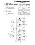
Figure 6: Multi-agent realtime monitoring system conceptual model. The continuous line is used
to indicate a communication between components through either email or SMS. The dotted line
was used to indicate a physical visit made to the location where the transformer is located.
P a g e | 21
Multi-agent based Realtime electric transformers Monitoring System
The above concept was not wholly dependent on the console operator as is the case in the current
situation. The solution of using multi-agents does much more that the operator ought to have
done manually or physically. System agents play a big role in making decisions on when to send
SMS and to whom. Unauthorized intruders will not be in a position of penetrating the system
without any given rights to view or get the transformer information.
In the current situation very few people are allowed to query the status of a transformer. It is
cumbersome and a long process to give someone access or permission to query the status of a
transformer. This solution makes it quite easy and simple to drop and give access rights to any
person. There is a lot of flexibility in terms of system operation. The system makes it easy to get
reliable information and data through the works of system agents. The data can be used for
decision making and benchmarking quality of service being offered.
P a g e | 22
Multi-agent based Realtime electric transformers Monitoring System
CHAPTER THREE: THE METHODOLOGY
3.1 System design methodology
Research methodology is a way to systematically solve the research problem. It may be
understood as a science of studying how research is done scientifically. (Kothari, 2004).
This section gives a description of research design, selected programming language and database
that will be used in the project for real-time monitoring of electric transformers.
3.2 System Design scope
This project covers a few transformers in Nairobi region and its environs such as Kiambu,
Ong’ata Rongai and Kitengela. This is the pilot area where Kenya power and Lighting Company
has installed GSM alarm system for monitoring transformer vandalism before it rolls out the
project to other regions within the country. Nairobi has the highest concentration of transformers
as compared with other areas measured in square kilometres. It also has the highest concentration
of skilled labour or manpower that is believed to be behind transformer vandalism. Transformer
vandalism is done by a skilled person who understands how it electrical structures and network
operates.
3.3 Frameworks for designing and Specification of MAS
Several frameworks exists that can be used to design and implement multi-agents systems. Some
of the frameworks are:i. MAS-CommonKADSmethodology(Spain) MAS-CommonKADSis based on Object
Oriented based methodologies. MAS-CommonKADS has the following development
phases:
Conceptualization phase, agents and their properties are identified;
Analysis phase, models are developed and analyzed;
Design phase, the models are put into operations;
Development and testing phase;
ii.
The Prometheus methodology (Australia) The Prometheus methodology consists of
three phases :-
System Specification phase.
The system is specified using goals and use case
scenarios and in terms of actions, percepts, and external data; and functionalities;
P a g e | 23
Multi-agent based Realtime electric transformers Monitoring System
Architectural design phase is where agent types are identified and it system’s
structure
Detailed design phase is where the details of each agent are defined in terms of
capabilities, data, events, and plans.
iii.
The Gaia Methodology (UK). Gaia methodology uses the analogy of human-based
organizations.
iv.
The MESSAGE Methodology ( Spain, Belgium) MESSAGE analysis and design
process is based on the Rational Unified Process (RUP). The methodology supports
the analysis and design of multi-agent systems that are flexible and can adapt to
specific kind of changes in a heterogeneous and dynamic environment.
v.
PASSI.
The formal specification of compositional architectures for multi-agent
systems is based on a task-based approach to multi-agent systems' design. As a result
of task analysis, hierarchical task models are specified at different levels of
abstraction as is the interaction between tasks. A close relation exists between the
different levels of task decomposition and the specification of the interaction between
tasks: the interaction is specified for each level within the task decomposition. Each
task is assigned to one or more agents. Agents themselves perform one or more (sub)
tasks, either sequentially or in parallel. The knowledge that agents have of themselves
and of other agents and the world is explicitly specified.
( Formal Specification of Multi-Agent Systems, 2012 ).
The PASSI methodology was been selected for this project. PASSI is a step-by-step requirementto-code method for developing multi-agent software that integrates design models and
philosophies from both object-oriented software engineering and MAS.
The reasons for choosing PASSI framework are as follows:
It is very simple to use;
Has got very clear steps;
PASSI allows reusability of code;
The PASSI model is made of five phases that includes.
System requirements model;
Agent Society model;
Agent implementation model;
P a g e | 24
Multi-agent based Realtime electric transformers Monitoring System
Code model and
Deployment model
The diagram below shows an overview of the five phases of PASSI model.
(Agents Identification, 2012).
Figure 7: Passi methodology diagram showing different steps in developing a multi-agent based
system.
3.3.1 Requirement Model
This model specifies systems requirements based on the agents and the purpose of the project.
This phase is subdivided into four steps namely:-
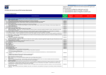
Figure 8: PASSI System requirement model, showing four steps of initial requirements phases.
i. Domain description step.
Doman description of the requirement model is a functional description of the system. It is
composed of hierarchical series whereby use case diagrams are implemented to represent the
P a g e | 25
Multi-agent based Realtime electric transformers Monitoring System
agents of the solution. The step uses use-case diagrams to make functional description of the
real-time multi-agent system for monitoring transformers. At this stage the functionality of the
system is described using sequence diagrams.
Figure 9: Agents Domain description using use case diagrams.
ii. Agent’s identification step.
This involves designing of responsibilities for each agent. The required behaviour of each agent
is described in detail. Social relationship of the agents is every important, how can agents
achieve their objectives. Among the agents that are implemented in this project are:
AlertreceiverAgent ,
smsAgent
EmailAgent
dialagent
CleanerAgent
RiskIdentifierAgent
VandalismReporter
P a g e | 26
Multi-agent based Realtime electric transformers Monitoring System
This is the separation of responsibilities of each agent. In Multi-agent monitoring system the
following are agents that were identified in the system.
Figure 10: Agent identification diagram showing different agents used in the project.
iii. Role identification.
This deals with the behaviour of an agent and how it communicates with other agents. It
describes the lifecycle of each agent in details. It uses sequence to describe the functionality of
agents
P a g e | 27
Multi-agent based Realtime electric transformers Monitoring System
iv. Task specification.
The behaviour of an agent is decomposed into tasks that each agent is supposed to perform in a
multi-agent system. The ability if an agent is represented using use case diagrams.
Figure 11: Task specification model showing tasks of different agents.
3.3.2 Agent Society Model
This is a model of the social interactions and dependencies among the agents involved in the
solution. This model involves two phases: - description of agent definition and domain ontology
description. Agent definition uses use case diagrams. Domain ontology described using class
diagrams. The class diagrams are described based on the concepts and actions.
Ontology Description
This is the use of class diagrams to describe the knowledge ascribed to individual agents and the
pragmatics of their interactions.
P a g e | 28
Multi-agent based Realtime electric transformers Monitoring System
<<Act>>
Detect intruder
<<Act>>
AlertReceiver
<<predicate>>
IsItrightformat
<<Act>>send(sms : text)
<<Act>>format(sms: text)
Matchtext(regularexpression)
<<concept>>
storeinDatabase
SMSid: int
Message: string
Eventtime: datetime
Txno: int
<<Act>>
Readnewsms
<<predicate>>
IsitVandalism
<<Act>>getauthorizedt(id: int)
<<Act>>send(sms: text)
Algorithm
<<Act>>
Recievesms
Interpretsms
<<Act>>call(phonecall)
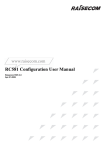
Figure 12: Domain descriptions of different agents used in the system. Sequence Diagram
This stage identifies the functionality of the multi-agent system of realtime monitoring
transformers. It shows behaviour of various agents used in the system. The following sequence
diagram shows the most important agents in the system. It shows intercommunication between
different agents.
Sensor
AlertReceiver
Database
Allow
reading
Send alerts
Alert Reader
Client
Relay alerts
Format alerts
Receive
queries
Make inquiries
Figure 13: Sequence diagram, showing the behaviour of egents in the system.
P a g e | 29
Multi-agent based Realtime electric transformers Monitoring System
3.3.3 Agent Implementation Model
The model describes the solution in terms of classes and actors, that is, methods. It is has got two
steps that is agent structure definition that uses class diagrams to describe the solution of agent
classes and agent behaviour that uses activity diagrams or state charts to describe behaviour of
each individual agent.
Code Completion Phase. The programming work continues for already defined classes.
Deployment Configuration Phase.Indicates where the agents will be located. They could be in
different servers or in different locations.
3.3.4 Code Model
The code model involves description of pattern reuse and coding. Use case diagrams in UML can
show code re-use or those parts that can be repeated.
3.3.5 Deployment Model
This stage allocates each agent to available processing units.
Figure 14: Deployment model, agents can be implemented on distributed networks. Cellular
network must be within reach
P a g e | 30
Multi-agent based Realtime electric transformers Monitoring System
3.4 Selected Programming Language
There are several types of programming languages available for use. Any can be used to do this
project but C-sharp (C#) programming language has been chosen because of many reasons. Csharp is an object-oriented language and is selected due to good functionalities. C-sharp has the
capability of using classes, component-oriented language, declarative and strong typing
programming language. It is a Microsoft product and found in .NET of Microsoft.
Other available programming languages are PowerBuilder Microsoft basic, C++, Oracle, JAVA
and many more are can also be used to do the project.
C-sharp (C#) programming language has been chosen for this project. Some of the reasons why
C# was chosen are because
C-sharp is an object-oriented language
Good functionalities
C-sharp has the capability of using classes,
component-oriented language, declarative
Strong typing programming language.
C# was used to implement AT commands. AT is an abbreviation for “Attention”. AT commands
are used to perform communication tasks through modems.
AT commands, with a GSM MODEM or mobile phone, can be used to access following
information and services:
Information and configuration pertaining to mobile device or MODEM and SIM card.
SMS services.
MMS services.
Fax services.
Data and Voice link over mobile network.
3.5 Database
MySQL database was used in this project. MySQL is an open source and thus good for
development and testing of applications. Reasons for picking this database were:
Open Source database. MySQL is an open source database and therefore can be used
freely without restrictions of licenses.
P a g e | 31
Multi-agent based Realtime electric transformers Monitoring System
Easy to learn and operate.
Can be used in a number of platforms such as Windows, Solaris, Linux
High security issues due to encryption of passwords stored in the database
Connecting to MySQL is easy and can be done through standard ODBC, TCP/IP.
3.6 GSM Modem
GSM modem is a wireless modem that is integrated accepts SIM cards. Thus it is easy to
communicate through a mobile network or operator. The GSM has the USB connectivity In this
project, GSM modem was used as a means of receiving alerts from motion detectors. GSM
modem provided a convenient way of receiving and sending SMS. The sensor alerts were
received through the GSM modem for development purposes and testing of the proposed system.
P a g e | 32
Multi-agent based Realtime electric transformers Monitoring System
CHAPTER FOUR: SYSTEM ANALYSIS AND DESIGN
Systems analysis of for Realtime monitoring of electric transformers was carried out by studying
existing systems and business processes.
Feasibilitystudy
This was carried out in order to determine whether the project of Realtime monitoring of electric
transformers was feasible or not. Goals and implications of the project were studied in details.
Feasibility study was carried out for the following main reasons
1. Technical reasons: This was to find out whether there was adequate technologically
knowhow to carry out the project. There was enough skilled manpower who understood
the company’s operations. The technical staff would provide guidance on operation of
motion detectors. IT staff were to provide technical assistance in terms of system that
were being used then.
2. Feasibility study helped to understand IT systems that were being used and if they would
be compatible with Realtime monitoring of electric transformers system. It was found out
that it was quite compatible and could interoperate seamlessly. Problems and weaknesses
of the existing systems were identified.
3. Financial implications were also noted but were to be handled as need arises since it was
manageable costs for the company.
4. Time factor was taken into consideration and this was to avoid taking too long for the
project to be put in use.
5. This project was intended to alert other stakeholders who are not members or staff of
Kenya Power such police and residents living or being served by the transformer. Mobile
numbers for this group were to be obtained but the company accepted to safeguard
privacy of the owners of SIM card numbers.
P a g e | 33
Multi-agent based Realtime electric transformers Monitoring System
This project went through normal Software Development Life Cycle that included the following
steps
Planning,
Analysis,
Design,
Implementation.
These steps are illustrated here below (Dennis, et al., 2006)
Planning
Analysis
Design
System
Prototype
Implementation
Implementation
System
Figure 15: Prototyping-based methodology of system.
Prototyping-based methodology was chosen for this project though not all phases were adopted
as shown in the modified figure of Prototyping-based methodology below.
Planning
Analysis
Design
System
Prototype
Implementation
Figure 16: Modified Prototyping-based methodology of system Analysis.
This shows that process of systems analysis that was done. The red color shows that
Note: Realtime monitoring of electric transformers project was not implemented as this was not
part of the objectives. That is why the above diagram has a little been modified. The arrow from
“system prototype” points to “design” instead of implementation. This shows that the
implementation part was not carried out.
P a g e | 34
Multi-agent based Realtime electric transformers Monitoring System
Why prototyping-based methodology.
Advantages
The system was available the users at the initial stage and could interact with easily.
New requirements from users were easily accommodated.
Ease of documentation was possible the users’ requirements were availed as the system was
being built.
Disadvantages
This methodology could easily lead to poor design if users’ requirements are not
harmonized and agreed upon within.
Planning
The stage was so fundamental for the system development process
Basics issues of the projects were handle
Project staff, their roles and activities, were appointed
Costs other financial issues taken care of
Work plan was instituted.
Analysis
This was very necessary in building logical system of Realtime monitoring of electric
transformers system.
a. Analysis strategy, strategy was developed to guide the team during the project
development process.
b. Requirements phase, the requirements of the Realtime monitoring of the electric
transformer system were gathered based on PASSI methodology (Refer to Chapter there).
PASSI methodology provided a well-documented steps of coming up with the user
requirements of a system. We used questionnaires to get deeper understand of the
teething problems of vandalism.
Design
Once the user requirements were obtained and were satisfactory to all team members, system
design begun. This is the phase when the system was actualized using the requirements that
were gathered at the requirements phase. The requirements were converted into a real system.
P a g e | 35
Multi-agent based Realtime electric transformers Monitoring System
Coding stage: computer programming was done using C# for the new system.
SystemDesignFlowchart
Start
Sensor Sends Alerts
No
Correct
format?
Main
DB
Save
Alert
Yes
Filter alerts
Alert No
contains OFF/FAIL/
TREMBLE?
Yes
Save to
Temp.
Temp
DB
Compare
Time/Alerts
No
Delete Alert temp
Yes
Greater than 5 Minutes
No
3 Alerts found?
Report Vandalism
Vandalized
Reports
End
Figure 17: System design flowchart for realtime monitoring of electric transformers system.
P a g e | 36
Multi-agent based Realtime electric transformers Monitoring System
CHAPTER FIVE: ANALYSIS OF RESULTS
During the time of working on this project, a questionare was created and sent via email
addresses to a number of people. The response was good and those who got the questionare also
send it to other people who positively responded to the questionare.
A total of fourty three (43) persons were sent the questionaire. When the period of data
collection elapsed, a total of thirty nine (39) people had responded.
100% of the respondents indicated the they have either heard or experienced vandalism of some
nature.
The questionare attempted to get actual facts from those who have been affected by vandalism.
Following were the analysis of each question
i.
Question 1 tested if the participants were aware that vandalism existed.
All the respondents answered yes to this question. This actually showed that vandalism
thrives in our country.
Figure 18: Awareness about vandalism. The pie chart shows 100% of the respondent knew that
vandalism exists.
ii.
Question 2 was to find out which of elelctric equipments was commonly vandalised
Transmission towers = 3 respondents
P a g e | 37
Multi-agent based Realtime electric transformers Monitoring System
electric cables
= 4 respondents
transformer
= 32 respondents
In terms of percentage
Transmission towers -- 3 / 39 = 07.69%
Electric Cables
-- 4 / 39 = 10.26%
Transformer
-- 32 / 39 = 82.05%
Figure 19: Vandalized equipment graph. The graph in Figure 16 shows that transformer had the
highest number of respondents of those who believed or have past experience vandalised electric
equipment. Hence this project focuses more on transformer vandlism as compared to other
electric equipments.
iii.
Question 3 was to know how the respondents learnt about a vandalised equipment.
The questionnaire gave five choices of which one was required to choose any or all of the
options given.
These were how the answers were distributed for the above question.
From a whistle-blower
= 1 respondents
From police
= 1 respondents
P a g e | 38
Multi-agent based Realtime electric transformers Monitoring System
Blackout (no electricity) = 16 respondents
KPLC staff
= 20 respondents
Everybody can see them = 1 respondents
In percentage the followning were results
From a whistle-blower -- 1 / 39 = 2.56%
From police
-- 1 / 39 = 2.56%
Blackout (no electricity) -- 16 / 39 = 41.02%
KPLC staff
-- 20 / 39 = 51.28%
Everybody can see them -- 1 / 39 = 2.56%
Figure 20: Source of vandalism information chart. Most of the repondents chose that they learnt
through Kenya power staff that an equipment has been vandalised in their area. In the event that
there is no power supply in many homes, most residents report their incidences to the nearest
Kenya Power officer through calling. Kenya power investigates the cause of power failure of
which the they record and inform their customers of what has happened. A few people leaving
next to the transformer knew that the equipment has been vandalized and mostly through visiting
or checking the transformer physically.
P a g e | 39
Multi-agent based Realtime electric transformers Monitoring System
iv.
Question 4 was to test impact of vandalism to a society
These were how the answers were distributed for the above question.
Extreme loss
= 23 respondents
Insignificant loss = 3 respondents
Not effect
= 13 respondents
The results above indecated that most of the respondents experience some loss caused by
vandalism of transformers.
Figure 21: Effects of vandalism. Showing that most of the respondents indicated vandalism
caused extreme loss to the lives and businesses.
P a g e | 40
Multi-agent based Realtime electric transformers Monitoring System
v.
Question 5 was intended for indept understanding of how society has been affected by
vandalism, how they cope with this vice as they go along with their normal and daily works.
This part provided and justified the need for technlogy to leverage the society from the
effects of vandalism. The question conatained different components that shade more light on
effects of vandalism. Analysis of this question can be summarized in a table as shown below.
Table 3: Impact of vandalism
Question
Strongly
Strongly
Agreed
disagreed
Economy can grow without availability of electric power.
1%
99%
Vandalism is not a good thing to our society.
100%
0%
Vandalism is not common in our country
1%
99%
Whenever vandalism occurs, Kenya power replaces the equipment 25%
75%
immediately without delay.
Communities affected by vandalism support Kenya Power in
60%
40%
100%
0%
meeting costs of replacing vandalized equipment.
There should be a form of alerting customers, Kenya power or
police if there is an attempt to vandalize electric equipment.
The results of the table above shows how vandalism as affected
P a g e | 41
Multi-agent based Realtime electric transformers Monitoring System
CHAPTER SIX: SYSTEM TESTING AND EVALUATION
This project focused on protection and prevention of transformer vandalism by sending SMS,
email messages, and dialing mobile numbers of those who have been authorized to receive such
information. The project highlighted algorithms of alerting security personnel, company
engineers and persons living around or being served by the transformer. The person who
received a vandalism alert was expected to raise an alarm. Maximum care was emphasized since
those involved in vandalism were mostly dangerous individuals who are always armed. Such an
alarm would scare away the vandalizers and save transformer.
This project tested on a few transformers that were fitted with motion detectors and capable of
sending SMS alerts through in-built SIM cards.
Whenever there was some motion (detector assumed that this was an intruder), vibration or
power failure detected, an SMS alert was send to a central receiver (control centre) by the sensor
installed on the transformer. Software algorithms through Multi-agent technology in this project
analyzed the alerts, made a conclusion on whether there was vandalism or not. The system
agents then alerted appropriate persons on what is happening around the transformer through
SMS, mail and even dialing the mobile phone numbers. Not every alert received meant there was
vandalism. Real-time monitoring of transformers project used three types of alerts, when
combined and received within a very short interval of time, computer algorithms concluded that
there was a form of vandalism. A time interval of five minutes was used in this project. The three
alerts are vibration alert, power failure and sensor switched off alert. If the three alerts were
received within five minutes from the same detector, then the system concluded that there was
some attempt of vandalism and those concerned would be informed by the computer based
system without involving any individuals.
The project of Real-Time monitoring of transformers was tested and evaluated by a group of
Kenya Power staff.
System Security and Control
The system was accessed by providing username and password. The ensured that there was no
unauthorized access to the system’s data. Not more than instances of an agent are allowed to be
active at the same time. This was to avoid conflicts or duplication of work in terms of sending,
receiving and analyzing of alerts from the sensor.
P a g e | 42
Multi-agent based Realtime electric transformers Monitoring System
Sensor Alert Processing
There were four types of messages were received from the sensor:1. PIR messages – type of sent when there is any motion around the transformer.
2. Device off was a message that is sent when the sensor is switched off. The sensor
had a backup battery. In case it was switched off, it could still send the alerts for
some time.
3. Vibration alert was sent whenever there is a shakeup within the transformer
4. Power failure alert was sent
when there was
power disconnection to the
transformer.
Any message or alert received through the agents in this project were checked and only alerts
coming with certain formats were allowed for processing. This project used a regular expression
to process the incoming alerts. All the sensors were configured to be sending alerts that had
specific format. If there is any change of alert format at the sensor level, the regular expression in
system must also be changed accordingly.
When a detector send an alert and the alert came in the correct format, that system agents first
checks if the transformer details had been captured and if not it registered it as a new transfomer
by capturing details such as the SIM number of the sensor installed on that particular
transformer, Transformer number and the location of the transformer automatically into the
system database. The system assigned the new transformer a unique identififaction in the system.
Normal opertional works such as line maintenance and breakdowns could also affect this system
since power must be switched off first. Realtime monitoring system was integrated with
Incidence management system. System checked if there was any maintenance or powerbreakdown in the Incidence management. In case of any, alerts from affected transformers were
not analyzsed. When an incidence was resolved, the Realtime montoring system was also
updated so that the system could start analysing alerts from the affected transfomer. us.
Realtime monitoring of transformers contains strong algorthims for generating for providing
reports that can be used to improve on services of the company.
A good example SAIDI (System Average interruption Duration index) which is the average
number of minutes a customer is without power in a year. Whenever there is vandalism, the
P a g e | 43
Multi-agent based Realtime electric transformers Monitoring System
vandalized equipment is not replaced immediately. Given the total number of customers the
company has, the system can calculate the average number of minutes a customer can go without
power.
SAIDI
=
Total number of customer- minutes
Total number of customers
Realtime monitoring of transformers system offers algorithms that calculates such efficiency
parameters.
SMS of the same message is send to the mobile numbers that are linked to the transformer.
Vandalismdrilltest.
A vandalism drill was carried out when the system was being evaluated. This was an assumption
that there was someone about to temper with the transformer. The engineers monitored the
behaviour of the system. For a test purpose, a person was sent to move around the transformer.
The sensor sent alerts showing that there was some motion around the transformer. When part of
the transformer structures was shaken a bit, touched or moved in a way, the sensor would sent an
alert of “TREMBLE”.
Steps
Setup and installation of Real-Time monitoring system in a laptop
Safaricom modem was connected to a laptop. The modem was used as sms-receiver from
motion alert sensors installed in some of the transformers.
SIM card number in the Safaricom modem was configured to receive alerts from some of
the sensors.
Observation and evaluation of the system took place.
P a g e | 44
Multi-agent based Realtime electric transformers Monitoring System
Simulation method
Modeled messages representing tremble, vibration and power off alerts were loaded into mobile
phones of those who were doing the testing and evaluation of the system.
A simulation of a sensor was carried out by sending the predefined SMS to the SIM card number
in the GSM modem connected to the laptop. SMS was sent many times as per the need at that
time until a desired behaviour of the system was achieved.
The type of messages that when received together constituted vandalism were:
The sensor device is off
There is tremble or vibration around the transformer
There is power-cut or power failure that is serving the transformer.
Any time an alert containing a substring of “OFF”, “FAIL” and “TREMBLE” is received, it is
saved in a separate database table for further monitoring.
Timing is a great factor here. These messages can be received different times but that still does
not mean there is vandalism. In this project a maximum of five minutes was used as a parameter
whereby the three alerts must all occur or found to be existing in the database. Any alert that has
stayed for more than five minutes is removed from the temporary database table. A difference of
time is calculated between the system(server) time and the time the event occurred at the
transformer.
Timing event was of great essence in this case. Five minutes was used as a time that the three
different types of SMS was expected
As soon as the first message was received, timing starts immediately and the message is held in a
temporary database table waiting for the other two to be received. If none was received within
five minutes, automatic system algorithms moved these messages into other database table for
recording purpose.When the second message was, received, its timing does not start from zero
but would pick the timing of the first message and likewise to the third type of message.
Receiving the three messages within five minutes meant there was an attempt of vandalism.
Freeing of the temporary database table ensured that delay in reading data from this table as
eliminated. The fewer the records, the faster they would be read. The oldest time a message
would stay in a temporary table was five minutes.
P a g e | 45
Multi-agent based Realtime electric transformers Monitoring System
Illustration
Let message 1 be M1, message 2 M2 and Message 3 M3.
If M1 is received at time T1, M2 at T2 and M3 at T3.
System reports vandalism if T1, T2 and T3 should be received within time 0 > (5-T1) ≤ 5
Time
M1(5-T1)
M2(5-T1)
M3(5-T1)
0
Figure 22: Simulation of alerts from a motion detector. It illustrated how three different
messages were received within a period of five minutes.
Once the Realtime monitoring of system got the three combinations of alerts coming from the
same transformer it was concluded that this was an attempt of vandalism. Reporting of such
cases started immediately. Reporting was done through SMS and email. The system reported
such cases to the client three times in a period of every five munites.
The table below shows sample of data received from different detectors installed in the
transformer.
Figure 23: Example of a reported vandalism through email. The system was a able to report a
simulated vandalism through an email.
P a g e | 46
Multi-agent based Realtime electric transformers Monitoring System
Table 4: Sample of alarm data received
ID
Alarm type
Location
EVENT TIME
015923
PIR
Makuweni District Hqs
30/10/2012,06:54:49
01660B
Vibration
Hilton Hotel
01/11/2012,16:24:23
04381
Power cut
Day star University
01/11/2012,23:30:17
13190
Device switch
Telkom_Machakos
02/11/2012,23:33:18
The table shows people to be contacted in case there was vandalism.
Table 5: Sample of contact persons
ID
Phone No.
Name
SMS
Dial
Email
015923
0722827340
David Korir
1
1
1
01660B
0728955588
Sam
0
1
0
1
0
1
Omondi
01660B
0724384527
Rose
Mwangi
Note: 1 means the person is authorized to receive the type of alert and vice versa.
Performance indicators
Below are some of the performance measurement methods or indicators used internationally.
The project automatically provided solutions for measuring these standards.
SAIFI is the average number of outages experienced by a customer in a year
CAIDI is the average duration (minutes) of an outage. It is the same as average repair
time (or service restoration time)
SAIDI is the average cumulative time (minutes) in a year that a customer is without
power
SAIFI
=
Total number of customer-interruptions
Total number of customers
P a g e | 47
Multi-agent based Realtime electric transformers Monitoring System
CAIDI
=
Total number of customer-minutes
Total no. of customer-interruptions
SAIDI
=
Total number of customer- minutes
Total number of customers
Figure 24: Sample Reports. The figure shows a sample of report that computer generated
calculation for “Average Interruption Duration Index” of a vandalized transformer within a given
period of time
P a g e | 48
Multi-agent based Realtime electric transformers Monitoring System
CONCLUSION
This report discussed the design, development, testing and evaluation of the multi-agent system
for use in real-time electric transformers monitoring system. The project proved to be quite
resourceful and reliable in relaying information about what was going on around the transformer
by using well-formulated computer algorithms.
Algorithms provided a strong capability of making decisions without any human intervention.
By receiving alerts from a particular detector, system agents were able to monitor the incoming
alerts for a certain period of time and in this case three minutes was used as the allowed time a
detector was expected to send different alerts. This was a flexible period of time and it could be
changed depending on the need.
The design was based on PASSI methodology which ensured the system interoperability was
strictly followed and its design done through internationally acceptable standards of software
development and design.
Development of the multi-agent system of real-time monitoring of electric transformers was
done through the use of C# (Csharp), which is Microsoft object-oriented programming language.
C# provided a strong platform for formulating algorithms that operated with external objects
such as modems.
It was not feasible to test the system by use of actual vandalism since its occurrence could not be
predicted. Hence the system was tested and evaluated through simulated process by sending
predefined text messages similar to those of a detector installed on an electric transformer.
Evaluation through simulation provided a good means of proving the systems resilience through
many tests until a desired behaviour was achieved.
Through simulation the system was able to report vandalism within a shortest time possible and
all the intended recipients received the alerts as was expected.
P a g e | 49
Multi-agent based Realtime electric transformers Monitoring System
REFERENCES
[1] Agents Identification, http://www.pa.icar.cnr.it/passi/Passi/AgentIdentification.html,
[accessed on November 2012]
[2] Barbara L. Ciaramitaro.(2012).Mobile Technology Consumption: Opportunities and
Challenges, IGI Global
[3] Chee Siang Ang and Panayiotis Zaphiris.(2009). Human Computer Interaction: Concepts,
Methodologies, Tools and Applications, Volume 3.
[4] Corporate Strategic Plan, http://www.kplc.co.ke, [accessed November 2012]
[5] Dennis, A., Wixom, B., & Roth, R. (2006). Systems Analysis and Design (3rd ed.). Hoboken, NJ:
John Wiley & Sons.
[6] Fordyse, K., Dunki-Jacobs, R., Gerard, B., Sell, R. and Sullivan, G.,(1992), “Logistics
Management System: an Advanced Decision Support System for the Fourth Decision Tier
Dispatch or Shortinterval Scheduling”, Production Operations Management, 1(1), pp70-86.
Gliedman, J. (1998) “Mission Control”, ZDNet Magazine,
[7] Formal Specification of Multi-Agent Systems: a Real- world Case
http://www.aaai.org/Papers/ICMAS/1995/ICMAS95-004.pdf,
[accessed on November 2012]
[8] GSM Power Alarm System http://www.gsmalarmsystems.com , [accessed on November
2012]
P a g e | 50
Multi-agent based Realtime electric transformers Monitoring System
[9] Hau-Ren Lu and Leether Yao, Design and Implement of Distribution Transformer
http://www.researchgate.net/publication/4292416_Design_and_Implement_of_Distribution_Tran
sformer_Outage_Detection_System [accessed on July 2012].
[10] Hayzelden Alex L. G. and Rachel A. Bourne.(2001).
Agent Technology for Communication Infrastructures.
[11] History and Milestones , www.kplc.co.ke, [accessed on November 2012]
[12] Katia P. Sycara. Multiagent Systems
http://www.aaai.org/ojs/index.php/aimagazine/article/viewArticle/1370,
[accessed on November 2012]
[13] Kothari C. R.(2004). Research Methodolgy methods and techniques, Second Edition,New
Age International (P) Ltd
[14] Kenya Power Monthly reports for different departments (Centralized servers) [accessed on
November 2012]
[15] Ladyada. PIR motion sensorsPyroelectric ("Passive") InfraRed sensors
http://www.ladyada.net/learn/sensors/pir.html, [accessed on November 2012]
[16] Macal Charles M. and Michael J.(2006). Introduction to Agent-based Modeling and
Simulation.Argonne National Laboratory
[17] Multi-Agent System: An Introduction to Distributed Artificial Intelligence
http://jasss.soc.surrey.ac.uk/4/2/reviews/rouchier.html, [accessed on November 2012]
[18] Muriithi Benson, Combating Vandalism in utilities
http://www.esi-africa.com/i/p/Benson-Muriithi_Closing.pdf [accessed November 2013]
P a g e | 51
Multi-agent based Realtime electric transformers Monitoring System
[19] Sardis Emmanuel, Anastasios Doulamis and Nikolaos Matsatsinis.(2006). Sensor Networks
and Multi-Agents in Industrial Workflows.
[20] Thomas L. Norman.(2007) Integrated Security Systems Design: Concepts, Specifications,
and Implementation, Butterworth-Heinemann.
[21] Wakefield Tony, Dave McNally, David Bowler and Alan Mayne.(2007) Introduction to
Mobile Communications: Technology, Services.
[22] Wooldridge Michael.(2009). An Introduction to MultiAgent Systems, Second Edition,John
Wiley & Sons
[23] Yoav Shoham and Kevin Leyton-Brown.(2009)Multiagent Systems Algorithmic, GameTheoretic, and Logical Foundations,Cambridge University press.
P a g e | 52
Multi-agent based Realtime electric transformers Monitoring System
APPENDICES
AppendixI:Code
AT commands
"AT" used to get the attention of the modem
"AT+CMGL=\"ALL\"" used for reading all the messages in a modem.
"AT+CMGD=" used for deleting a message from the modem once it has been read
"AT+CMGF=1" used to set message format
"AT+CPMS=\"SM\"" used to select message storage.
"AT+CMGS=\"" + cellNo used to send sms to a mobile number
Regular expression used in the system is.
(@"\+CMGL:
(\d+),""(.+)"",""(.+)"",,\""(.+)""\r\nHOST_ID(.+)\r\n(.+)\r\nLOCATION(.+)\r\nEVENT
TIME:
\r\n(.+)\r\n")
Any solved incidence is updated with status 6 as shown in the code below.
DbCommandIncidence.CommandText = "select * from tbl_incidences where installation_no = '"
+ sms[2] + "' and status <> 6";
Alerts that has the either of words, ‘OFF’, ‘FAIL’ or ‘TREMBLE’ if all combined constitute a
vandalism.
if (sms[3].Contains("OFF"))
{
DbCommand.CommandText = "INSERT INTO TBL_RISKYALERTS(ID,
MESSAGE,FULL_MESSAGE,EVENTTIME,DATETIME) VALUES(" +
id + ",'OFF','" + sms[3] + "','" + sms[5] + "'," + datetime + ")";
try
{
DbCommand.ExecuteNonQuery();
}
catch (OdbcException ex)
{
P a g e | 53
Multi-agent based Realtime electric transformers Monitoring System
}
}
if (sms[3].Contains("FAIL"))
{
DbCommand.CommandText = "INSERT INTO TBL_RISKYALERTS(ID,
MESSAGE,FULL_MESSAGE,EVENTTIME,DATETIME) VALUES(" +
id + ",'FAIL','" + sms[3] + "','" + sms[5] + "'," + datetime + ")";
try
{
DbCommand.ExecuteNonQuery();
}
catch (OdbcException ex)
{
}
}
if (sms[3].Contains("TREMBLE"))
{
DbCommand.CommandText = "INSERT INTO TBL_RISKYALERTS(ID,
MESSAGE,FULL_MESSAGE,EVENTTIME,DATETIME) VALUES(" +
id + ",'TREMBLE','" + sms[3] + "','" + sms[5] + "'," + datetime + ")";
try
{
The system checks if the three above alerts exist in the system at the same time.
DbCommand.CommandText = "select id,count(*) from tbl_riskyalerts group by id
having "+
"count(*) >= 3";
Whenevr a new sensor installed, the details of the sensor are automatically capture once the first
SMS is received by Realtime Monitoring of transformers system.
DbCommand.CommandText = "select * from tbl_txdetails where txno = '" + tx + "'";
OdbcDataReader DbReader = DbCommand.ExecuteReader();
DataTable dataTable = new DataTable();
dataTable.Load(DbReader);
rowcount = rowcount = dataTable.Rows.Count;
if (rowcount == 0)
{
DbCommand.CommandText = "INSERT INTO TBL_TXDETAILS(TXNO,
SIMNO,LOCATION) VALUES('" + tx + "','" + sms[1] + "','" + sms[4] + "')";
try
{
P a g e | 54
Multi-agent based Realtime electric transformers Monitoring System
DbCommand.ExecuteNonQuery();
}
catch (OdbcException)
{
}
Sample code for calculating SAIDI as one of the performance indicators of a utility firm.
DbCommand.ExecuteNonQuery();
}
catch (OdbcException ex) { } }
string strStartDate = startdate.Text;
string strEndDate = enddate.Text;
strStartDate = strStartDate.Substring(6, 4)+
strStartDate.Substring(3, 2)+
strStartDate.Substring(0, 2);
strEndDate = strEndDate.Substring(6, 4) +
strEndDate.Substring(3, 2) +
strEndDate.Substring(0, 2);
DbConnection.Open();
OdbcCommand DbCommand = DbConnection.CreateCommand();
OdbcDataAdapter adapter = new OdbcDataAdapter();
DbCommand.Connection = DbConnection;
DataTable datableInicidences = new DataTable();
DbCommand.CommandText = "select * from tbl_incidences" +
" where concat(SUBSTRING(occured_time, 1, 4),SUBSTRING(occured_time, 6,
2),SUBSTRING(occured_time, 9, 2))" +
" >='" + strStartDate + "'"+" and " +
"concat(SUBSTRING(resolved_time,
1,
4),SUBSTRING(resolved_time,
6,
2),SUBSTRING(resolved_time, 9, 2))" +
" <='" + strEndDate+"'";
try
{
OdbcDataReader DbReader = DbCommand.ExecuteReader();
datableInicidences.Load(DbReader);
rowcountIncidences = rowcountIncidences = datableInicidences.Rows.Count;
}
catch (OdbcException ex)
{
MessageBox.Show(ex.Message);
}
P a g e | 55
Multi-agent based Realtime electric transformers Monitoring System
if (rowcountIncidences > 1 )
{
total_duration = 0;
for (i = 0; i < rowcountIncidences; i++)
{
txt_starttime = datableInicidences.Rows[i].ItemArray[2].ToString().Substring(0, 4) +
datableInicidences.Rows[i].ItemArray[2].ToString().Substring(5, 2) +
datableInicidences.Rows[i].ItemArray[2].ToString().Substring(8, 2) +
datableInicidences.Rows[i].ItemArray[2].ToString().Substring(11, 2) +
datableInicidences.Rows[i].ItemArray[2].ToString().Substring(14, 2);
txt_endtime = datableInicidences.Rows[i].ItemArray[3].ToString().Substring(0, 4) +
datableInicidences.Rows[i].ItemArray[3].ToString().Substring(5, 2) +
datableInicidences.Rows[i].ItemArray[3].ToString().Substring(8, 2) +
datableInicidences.Rows[i].ItemArray[3].ToString().Substring(11, 2) +
datableInicidences.Rows[i].ItemArray[3].ToString().Substring(14, 2);
starttime = Convert.ToDecimal(txt_starttime);
endtime = Convert.ToDecimal(txt_endtime);
total_duration = (endtime - starttime) + total_duration;
totalcustomers
Convert.ToInt32(datableInicidences.Rows[i].ItemArray[4].ToString());
}
}
listViewReports.View = View.Details;
listViewReports.GridLines = true;
listViewReports.FullRowSelect = true;
listViewReports.View = System.Windows.Forms.View.Details;
if (totalcustomers > 0)
{
saifi_index
=
Convert.ToDouble(totalcustomers);
Convert.ToDouble(total_duration)
A sample of email that was send by the system is shown in the figure below
P a g e | 56
Multi-agent based Realtime electric transformers Monitoring System
=
/
AppendixII:Database
Database
MySQL is a relational database. This database was used in this project. The following are the
reasons why the database was chosen for this project:
Open Source database. MySQL is an open source database and therefore can be used
freely without restrictions of licenses.
Easy to learn and operate.
Can be used in a number of platforms such as Windows, Solaris, Linux
High security issues due to encryption of passwords stored in the database
Connecting to MySQL is easy and can be done through standard ODBC, TCP/IP.
P a g e | 57
Multi-agent based Realtime electric transformers Monitoring System
AppendixIII:Installationmanual
Source of installations files of MySQL database files and agent application software can be a
Hard disk, flash-disk, external hard-disk, compact disks or shared from another computer
through TCP/IP network.
Installations processed involved to steps.
a) Database setup.
Only one central Database was installed in a computer and this served as a central server for
different agents.
Database was installed through existing files that have already been stored in a storage device.
This process created database tables and views that were used in this project.
Open MySQL administrator module
Figure 25: MySQL administrator system for setting up database files
Choose restore and click “Open Backfile”
P a g e | 58
Multi-agent based Realtime electric transformers Monitoring System
Figure 26: Backed-up database files to create system database.
Locate the file that contains database files.
Figure 27: Locate the database files. Open the database file once found creation starts
immediately
b) Software installation.
In Real-time monitoring of electric transformers system, each agent comes with its own
installation files. Installation process is the same for all agents. This manual used shows how to
install “alertreceiver” in a computer.
Locate where files are stored and click setup.
Figure 28: Software setup. Clicking on setup starts installation process.
Installation does not take long its operational immediately.
P a g e | 59
Multi-agent based Realtime electric transformers Monitoring System
Figure 29: Launching application. Once the installation is complete, the system is immediately
launched. It does require manual interface
P a g e | 60
Multi-agent based Realtime electric transformers Monitoring System
AppendixIV:UserManual
Multi-agent Real-time monitoring of electric transformers system are independent programs that
does not require much of a user’s input as compared with other systems.
However, total exclusion of users cannot be avoided and a few users must gain access to the
system for administrative purposes.
System login
For one to access any data from the system, there must be some authentication first through
logging in. This is to bar or stop any unauthorized persons from accessing or tempering with the
system’s data or its operations. System users are created depending on available profiles and
roles. These profiles and roles categorize users depending on what a user is expected to do in the
system. Unauthorized access is not allowed in the system or part of the system.
Figure 30: System login. Shows how a user can log into the Real-time monitoring of
transformers system. A user must provide a user name and password in order to access the
system. Without which the system will not grant any permission to access the system.
System administrators can have superior access to the system and can manage and control all
users in the system.
P a g e | 61
Multi-agent based Realtime electric transformers Monitoring System
Figure 31: System navigation. The figure shows how a user can be removed from the system.
To get information from the system, queries can be executed. Several queries can be obtained
depending on the profile of a particular user.
Figure 32: System menus. The figure illustrates how a system controlled query can be executed
by a user.
P a g e | 62
Multi-agent based Realtime electric transformers Monitoring System
Figure 33: Received alerts. These data is automatically received from the motion detector.
Figure 34: Registered transformers. Any new transformer is registered automatically by the
system.
Interruption indices
There are several reports that can be mined from the systems
Figure 35: Interruption Indices illustrates how different International standard reports can be
accessed
P a g e | 63
Multi-agent based Realtime electric transformers Monitoring System
AppendixV:SampleQuestionnaire
This questionnaire was intended to collect information for a system development project that
would enable Police, Kenya Power and its customers receive alerts whenever there is an attempt
of transformer vandalism. This aided in understanding urgent need for computer software for
Real-time monitoring of transformers. Information contained in this questionnaire was treated
confidentially and was only shared with the interviewee at the end of the project period.
Questionnaire
Master of Science in Computer Science Questioner
This questionnaire was intended to collect information for a system development project that
would enable Police, Kenya Power and its customers receive alerts whenever there is an attempt
of transformer vandalism. This aided in understanding urgent need for computer software for
Real-time monitoring of transformers. Information contained in this questionnaire was treated
confidentially and was only shared with the interviewee at the end of the project period.
1) Have you heard or experienced vandalism of any electricity equipment? (Choose Yes or No)
Yes
( )
No ( )
2) Which one of the following equipment is more vulnerable to vandalism? (Tick only one)
Transmission Towers
( )
Electricity cables
( )
Transformer
( )
3) How did you get to know the above information about vandalism? (Can tick more than one)
From a whistle-blower
( )
From police
( )
Blackout (no electricity) ( )
P a g e | 64
Multi-agent based Realtime electric transformers Monitoring System
KPLC staff
( )
Everybody can see them ( )
4) How did the vandalized equipment affect you or your business? (Tick only one)
Extreme loss
( )
Insignificant loss( )
Not effect
( )
5) In the table below, kindly rate each statement; whereby 5 represents you strongly agree with
statement and 1 you strongly disagree with the statement.
Effects of vandalism
5
4
3
2
1
Economy can grow without availability of electric power.
Vandalism is not a good thing to our society.
Vandalism is not common in our country
Whenever vandalism occurs, Kenya power replaces the equipment
immediately without delay.
Communities affected by vandalism support Kenya Power in meeting
costs of replacing vandalized equipment.
There should be a form of alerting customers, Kenya power or police if
there is an attempt to vandalize electric equipment.
Comments…………………………………………………………………………………………
………………………………………………………………………………………………………
………………………………………………………………………………………………………
P a g e | 65
Multi-agent based Realtime electric transformers Monitoring System
………………………………………………………………………………………………………
………………………………………………………………………………
Your name (Optional)……………………………………………Mobile……………………
Email…………………………………Occupaton…………………………………………...
THANK YOU FOR YOUR COOPERATION
P a g e | 66
Multi-agent based Realtime electric transformers Monitoring System
AppendixVI:Sampleresponsestothequestionnaire
Sample1
Master of Science in Computer Science Questionnaire
This questionnaire was intended to collect information for a system development project that
would enable Police, Kenya Power and its customers receive alerts whenever there is an attempt
of transformer vandalism. This aided in understanding urgent need for computer software for
Real-time monitoring of transformers. Information contained in this questionnaire was treated
confidentially and was only shared with the interviewee at the end of the project period.
Questionnaire
1) Have you heard or experienced vandalism of any electricity equipment? (Choose Yes or No)
Yes
(√)
No ( )
2) Which one of the following equipment is more vulnerable to vandalism? (Tick only one)
Transmission Towers
()
Electricity cables
()
Transformer
(√)
3) How did you get to know the above information about vandalism? (Can tick more than one)
From a whistle-blower ( )
From police
()
Blackout (no electricity) (√)
KPLC staff
()
Everybody can see them ( )
4) How did the vandalized equipment affect you or your business? (Tick only one)
Extreme loss ( )
P a g e | 67
Multi-agent based Realtime electric transformers Monitoring System
Insignificant loss( )
Not effect
(√)
5) In the table below, kindly rate each statement; whereby 5 represents you strongly agree with
statement and 1 you strongly disagreewith the statement.
Effects of vandalism
5
4
3
2
Economy can grow without availability of electric power.
Vandalism is not a good thing to our society.
√
√
Vandalism is not common in our country
Whenever vandalism occurs, Kenya power replaces the equipment
1
√
√
immediately without delay.
Communities affected by vandalism support Kenya Power in meeting
√
costs of replacing vandalized equipment.
There should be a form of alerting customers, Kenya power or police if
√
there is an attempt to vandalize electric equipment.
6) Comments………………………………………………………………………………………
…………………………………………………………………………………………………
…………………………………………………………………………………………………
……………………………………………………………………………………….
Your name
(Optional)..Peter……………………………Mobile…0700657821…………………
Email…[email protected]………………………………Occupaton…Engineer………
THANK YOU FOR YOUR COOPERATION
P a g e | 68
Sample2
Master of Science in Computer Science Questionnaire
This questionnaire was intended to collect information for a system development project that
would enable Police, Kenya Power and its customers receive alerts whenever there is an attempt
of transformer vandalism. This aided in understanding urgent need for computer software for
Real-time monitoring of transformers. Information contained in this questionnaire was treated
confidentially and was only shared with the interviewee at the end of the project period.
Questionnaire
7) Have you heard or experienced vandalism of any electricity equipment? (Choose Yes or No)
Yes
(Y )
No
( )
8) Which one of the following equipment is more vulnerable to vandalism? (Tick only one)
Transmission Towers
( )
Electricity cables
( )
Transformer
(Y )
9) How did you get to know the above information about vandalism? (Can tick more than one)
From a whistle-blower
( )
From police
( )
Blackout (no electricity) ( Y )
KPLC staff
( Y)
Everybody can see them ( )
10) How did the vandalized equipment affect you or your business? (Tick only one)
Extreme loss
( )
Insignificant loss( )
Not effect
P a g e | 69
(Y )
11) In the table below, kindly rate each statement; whereby 5 represents you strongly agree with
statement and 1 you strongly disagree with the statement.
Effects of vandalism
5
4
3
2
Economy can grow without availability of electric power.
Vandalism is not a good thing to our society.
1
1
5
Vandalism is not common in our country
1
Whenever vandalism occurs, Kenya power replaces the equipment
2
immediately without delay.
Communities affected by vandalism support Kenya Power in meeting
1
costs of replacing vandalized equipment.
There should be a form of alerting customers, Kenya power or police if
5
there is an attempt to vandalize electric equipment.
12) Comments……………………………………………………………………………………
Vandalism is a very bad vice and Kenya power and the government should try as much as
possible to tame it
13) Your name
(Optional)……………………………………………Mobile…0722299164…………………
Email…[email protected]……………Occupaton…Systems analyst…………...
THANK YOU FOR YOUR COOPERATION
P a g e | 70
Sample3
Master of Science in Computer Science Questionnaire
This questionnaire was intended to collect information for a system development project that
would enable Police, Kenya Power and its customers receive alerts whenever there is an attempt
of transformer vandalism. This aided in understanding urgent need for computer software for
Real-time monitoring of transformers. Information contained in this questionnaire was treated
confidentially and was only shared with the interviewee at the end of the project period.
Questionnaire
14) Have you heard or experienced vandalism of any electricity equipment? (Choose Yes or No)
Yes
(* )
No ( )
15) Which one of the following equipment is more vulnerable to vandalism? (Tick only one)
Transmission Towers
( )
Electricity cables
( )
Transformer
(* )
16) How did you get to know the above information about vandalism? (Can tick more than one)
From a whistle-blower
( )
From police
( )
Blackout (no electricity) ( * )
KPLC staff
( )
Everybody can see them ( )
17) How did the vandalized equipment affect you or your business? (Tick only one)
Extreme loss
( )
Insignificant loss( * )
Not effect
P a g e | 71
( )
18) In the table below, kindly rate each statement; whereby 5 represents you strongly agree with
statement and 1 you strongly disagree with the statement.
Effects of vandalism
5
4
3
2
Economy can grow without availability of electric power.
1
1
Vandalism is not a good thing to our society.
4
Vandalism is not common in our country
2
Whenever vandalism occurs, Kenya power replaces the equipment
2
immediately without delay.
Communities affected by vandalism support Kenya Power in meeting
1
costs of replacing vandalized equipment.
There should be a form of alerting customers, Kenya power or police if
5
there is an attempt to vandalize electric equipment.
19) Comments………for transformers the fears among public are that vandalism is purported to
be done by kplc staffs since they are the ones with technical knowhow of how to siphon
transformer oil. BUT on electrical cables, its members of public who steal as the copper
metal I hear is bought better by scrap metal dealers that other metals…………………….
Your name
(Optional)………Thuo……………………………………Mobile……770230605…………
Email……[email protected]……………Occupaton………banker……………………
THANK YOU FOR YOUR COOPERATION
P a g e | 72
Sample4
Master of Science in Computer Science Questionnaire
This questionnaire was intended to collect information for a system development project that
would enable Police, Kenya Power and its customers receive alerts whenever there is an attempt
of transformer vandalism. This aided in understanding urgent need for computer software for
Real-time monitoring of transformers. Information contained in this questionnaire was treated
confidentially and was only shared with the interviewee at the end of the project period.
Questionnaire
20) Have you heard or experienced vandalism of any electricity equipment? (Choose Yes or No)
Yes
(√ )
No ( )
21) Which one of the following equipment is more vulnerable to vandalism? (Tick only one)
Transmission Towers
( )
Electricity cables
(√ )
Transformer
( )
22) How did you get to know the above information about vandalism? (Can tick more than one)
From a whistle-blower
( )
From police
( )
Blackout (no electricity) (√ )
KPLC staff
( )
Everybody can see them ( )
23) How did the vandalized equipment affect you or your business? (Tick only one)
Extreme loss
(√ )
Insignificant loss( )
Not effect
P a g e | 73
( )
24) In the table below, kindly rate each statement; whereby 5 represents you strongly agree with
statement and 1 you strongly disagree with the statement.
Effects of vandalism
5
4
3
2
Economy can grow without availability of electric power.
Vandalism is not a good thing to our society.
1
√
√
Vandalism is not common in our country
√
Whenever vandalism occurs, Kenya power replaces the equipment
√
immediately without delay.
Communities affected by vandalism support Kenya Power in meeting
√
costs of replacing vandalized equipment.
There should be a form of alerting customers, Kenya power or police if
√
there is an attempt to vandalize electric equipment.
25) Comments………………………………………………………………………………………
…………………………………………………………………………………………………
…………………………………………………………………………………………………
…………………………………………………………………………………………………
Your name
(Optional)……………………………………………Mobile…+254722345884……………
…… Email…[email protected]………occupation……..Systems Analyst
THANK YOU FOR YOUR COOPERATION
P a g e | 74