1
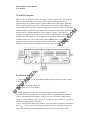
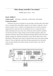
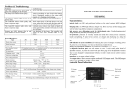
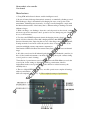
Photosynthetic solar controller
User manual
Main features:
1, Using SCM and dedicated software, enables intelligent control;
2, By rate of battery discharge characteristic accurately, as amended by discharge control.
Final discharge voltage is determined by discharging rate curve control points of the
amendments, eliminating mere inaccuracy of voltage controlled amplifier, comply with
the inherent characteristics of the battery, that is, different ending of discharge rate with
different voltages.
3, With over charge, over discharge, electronic overload protection, short circuit, a unique
anti-reverse protection automatic control; protection does not damage any part of the
above, no fire insurance;
4, Uses the series PWM Charger main circuit, the charging circuit voltage loss charging
circuit of diodes reduced by almost half, charging efficiency than PWM High 3%-6% ,
Increased electricity time; improving the recovery of the charge, the normal straight full,
floating automatic control mode causes the system to have a longer service life; at the
same time with high accuracy temperature compensation;
5And intuitive LED Led indicates the current battery State, so that the users understand
usage;
6, All of the controls used in all industrial-grade chip (only for I Industrial controller), in
the cold, hot, humid environment to run freely. While using the crystal oscillator timing
control, precision control of timing;
7Cancellation of potentiometer control set-point, and use the Flash Memory records the
control point, for the settings to digital, eliminated by potentiometer vibration
displacement, make control points appear such as drift error reduced accuracy, the
reliability factor;
8, The use of digital LED Display and set, one-click operation can complete all settings,
with easy and intuitive,
9All seal completely water-proof ( -S ) Has completely waterproof performance.
Photosynthetic solar controller
User manual
System Description:
This controller is designed for DC power supply system of solar energy, solar-powered
direct current street lamp system design, and use special intelligent controller for
computer chips. One-click tact switch, complete all the actions and settings. With short
circuit, overload, unique anti-reverse connection protection, full, automatic shutdown,
restored full protection measures, detailed charge indicates, battery status, load and fault
indication. This controller through computer chip on battery of end voltage, and discharge
current, and environment temperature, involved battery capacity of parameter for
sampling, through dedicated control model calculation, implementation meet battery
characteristics of discharge rate, and temperature compensation amendment of efficient,
and high accurate rate control, and used has efficient PWM battery of charging mode,
guarantee battery work in best of State, greatly extended battery of using life. With
multiple operating mode, the output mode selected to meet user needs.
Installation and use:
1, Controllers, fixed to a solid, high current models require to ensure the vents to ensure
heat dissipation.
Overall dimensions: 140 × 90.5 (mm)
Mounting hole size: 133.5 × 70(mm)
2, And the preparation of the wire: wire stranded copper conductor insulation is
recommended. First determine the wire length, in the case of guarantee the installation
location, minimizing the line length to reduce power loss. According to Max 4A/mm2
selection of current density copper wire cross-sectional area, the controller on one side of
the line head stripped 5mm of insulation.
3, First connected controller battery terminals, and on the other end attached to the battery,
note +
— Do not reverse. If connected correctly, the led (2) should be on, press the
keys to check. Otherwise, check whether you want. In case of reverse will not fire
Photosynthetic solar controller
User manual
insurance and damage to the controller any parts. Fuses only as a final circuit controller
itself damaged short circuit protection.
4, Conductors, connections, solar cell, first connect to the controller glazing the terminals
of the battery, and then connect the other end to light on the battery, note +
— Do not
reverse, if there is sunshine, charging light should be on. Otherwise, check whether you
want.
5, Load connections, load on the load line access controller the output, note +
— Do
not reverse to avoid burn out appliances.
6, Then light conductors should be at the bottom terminal of the battery and load one
radian prevent rain along the wire into the controller.
Instructions for use:
Charging and overpressure indicates: Dang system connection normal, and has Sun
irradiation to light battery plate Shi, charging led (1) for green often lit, said system
charging circuit normal; Dang charging led (1) appears green fast Flash Shi, description
system had voltage, processing see fault processing content; charging process using has
PWM way, if occurred had placed action, charging first to reached upgrade charging
voltage, and keep 10 Minutes, then fell to direct charge voltage, keeping 10 minutes to
activate the battery, avoiding vulcanization mold, and finally fell to floating charge
voltage and keep floating charge voltage. If it has not happened, there will be no lifting
the charging method in case the battery water loss. The best automatic control process
will enable battery charging effect and security or to extend its service life.
Photosynthetic solar controller
User manual
Battery State indicates: battery voltage in normal range Shi, State led (2) for green Shine
Chang; full Hou State led for green slow flash; Dang battery voltage reduced to owes
pressure Shi State led became orange yellow; Dang battery voltage continues to reduced
to had placed voltage Shi, State led (2) becomes red, at this time controller will
automatically close output, reminded user timely supplementary power. When battery
voltage recovery to normal working range automatically output open action status led (2
of) turns green;
Load indicating: When the load when opened, the load indicator (3) Shine Chang. If the
load current exceeds the controller 1.25 times the rated current of 60 seconds, or the load
current exceeds the controller 1.5 times the rated current of 5 seconds, the indicator (3) to
red slow flashing, overload, the controller turns off the output. When the load or the load
short-circuit fault occurs, the controller will immediately close the output, the indicator (3)
Flash. When the above behavior occurs, users should carefully check the load connected,
disconnect the faulty after loading, press the button once,30 seconds after the return to
normal work, or wait until the next day to work properly.
Modes settings:
Set method: Press the switch button 5 seconds, mode (MODE) displays a number LED
blinking, release the button, each press convert one number at a time, until the LED on
the displayed number to the user from the table that correspond to the pattern used by
digital stop key, wait until the LED digital does not flash setting is complete. Press the
button once,LED digital lit, and observe that the value set.
Pure optical control mode (0): When you no sun, light intensity drops to start point, the
controller delay 10 minutes after you confirm the start signal, open load, load start
working; when the Sun is, light intensity rose to the launch point, controller delayed 10
minutes confirm close the output signal back to close out, load stops working.
Light + delay (1-9,0.-5. ) Security: startup procedure ibid. When the load is working to set
time off load and time setting shown in the following table.
General controller (6. ): This method only on light control, output delay time control
function, as well as the related features, keep all other functions, as a general universal
controller with ( that is, output on or off by pressing the control load ).
Debug way (7 time.) : Used for system debugging, and pure light patterns are the same,
only cancelled the judgement light signals control the output of 10min delay, keep all
other features. Light signal that is connected to the load, there are optical signal switching
load, convenient installation and debugging check correctness of system installation.
Output model description: When you stop LED displays, the setting mode automatically
deposited MCU internal e ROM, power will not be lost, work pattern descriptions are
shown in the following table:
Photosynthetic solar controller
User manual
( Note: when selecting a LED digital decimal mode, the numeric decimal long, have no
effect on the overall performance of the controller, will only be used for case sensitive )
Advanced
Work mode
LED Display
Work mode
LED Display
Work mode
Optically
6
Optically
2
Optically
BIOS features
Setup
tables:
LED Display
0
controlled turn
controlled
on + light off
opening
hour
controlled
+6
opening
delay
hour
close
1
Optically
7
controlled
opening
hour
+1
close
2
controlled
opening
+7
8
controlled
opening
+2
delay
+13
hours delayed
delay
close
close
Optically
hour
Optically
3
opening
hour
delay
close
Optically
controlled
delay
+12
Light
open
controlled
Optically
+14
hours
open +8 hour
delay to turn
delay close
off
4
close
3
Optically
9
controlled
opening
hour
+3
delay
Optically
5
Optically
controlled
controlled
open +9 hour
open +15 hour
delay close
delay close
close
4
Optically
0.
controlled
opening
Optically
6.
controlled
+4
Universal
control modes
open +10 hour
hours delayed
delayed close
close
5
Optically
1.
Light
open
controlled
+11 hour delay
open +5 hours
to turn off
delayed close
7.
Debug mode
Photosynthetic solar controller
User manual
Common symptoms and treatment:
At the time of the following situations,
please follow the following checks:
No lights and displays show
When direct sunlight light solar panel, the
Green
Color charge indicator (1) No lights;
Charging indicator (1) Flash;
Load indicators (3) Light, but no output;
Load indicators (3) Flash and no output;
Load LEDs (3) Slow Flash, and no output
Led (2) To red, and no output;
Solution
Check that the battery is properly
connected, connection reliability
Check both ends of the battery power
wiring is correct,
Reliability of contact;
Overpressure system voltage. Battery
open circuit, check battery
Connection reliability; or charging circuit
damage;
Please check using equipment is
connected correctly, reliable;
Output short circuit, check the output line,
after removing all the load, press the
switch on, 30 Seconds after the controller
and normal output;
Load power more than the rated power,
decrease the electrical equipment,
A push of a button, 30 Seconds back after
output
Battery discharge, automatic recovery
after fully charged;
Photosynthetic solar controller
User manual
Technical specifications:
Model
GH5A
GH10A
GH15A
GH20A
Total charge
5A
10A
15A
20A
current
Total load current 5A
10A
15A
20A
System voltage
12V ; 24V/12V AUTO
Overload and short circuit protection
1.25Times of rated current 60 Second, 1.5
Times of rated current 5 Second overload
protection, 3 Times the rated current of
short circuit protection
No-load loss
5mA
Charging circuit voltage drop
Not more than 0.26V
Discharge circuit pressure drop
Not more than 0.15V
Overpressure protection
17V
×2/24V
Working temperature
Industrial grade; -35 To +55 (The
suffix I
Upgrade charge voltage
14.6V
×2/24V ; (Hold time: 10min )
(Discharge appears only when calling)
Direct filling charge voltage
14.4V
×2/24V ; (Hold time: 10min
Floating charge
13.6V
×2/24V ; (Maintenance time:
until the reduced charge return voltage)
Charge return voltage
13.2V;×2/24V
Temperature compensation
-5mv/ /2V (Lift, direct charging, floating
charge, charge return voltage
compensation)
Voltage voltage
12.0V;×2/24V
Over discharge voltage
11.1V- The initial over discharge voltage
discharge rate compensation amendment
(no load voltage); ×2/24V
Over discharge return voltage
12.6V
×2/24V
Control mode
Charging for PWM Pulse width adjust