1
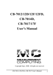
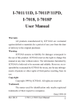
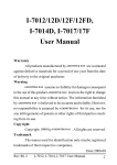
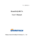
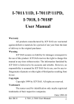
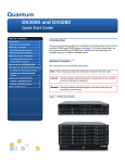
V1.0 2007.7.11
RemoDAQ-8018B Module
User’s Manual
Beijing DSLC Technology Co.,Ltd
Copyright Notice
This document is copyrighted, 2005, by Beijing DSLC
Technology Co.,Ltd.
All rights are reserved. Beijing DSLC Technology Co.,
Ltd reserves the right to make improvements to the products
described in this manual at any time without notice.
No part of this manual may be reproduced, copied,
translated or transmitted in any form or by any means without
the prior written permission of Beijing DSLC Technology
Co.,Ltd. Information provided in this manual is intended to
be
accurate
and
reliable.
However,
Beijing
DSLC
Technology Co.,Ltd assumes no responsibility for its use, or
for any infringements upon the rights of third parties, which
may result from its use.
Acknowledgments
RemoDAQ is a trademark of Beijing DSLC Technology
Co.,Ltd.
Edition 1.0
Oct. 2006
Additional Information and Assistance
1.
Visit the DSLC websites at www.DSLC.com.cn where
you can find the latest information about the product.
2.
Contact your distributor, sales representative, or DSLC's
customer service center for technical support if you need
additional assistance. Please have the following information
ready before you call:
Product name and serial number
Description of your peripheral attachments
Description of your software (operating system,
version,application software, etc.)
A complete description of the problem
The exact wording of any error messages
Table of Contents
1 INTRODUCTION .......................................................... 6
1.1 PIN ASSIGNMENT & SPECIFICATIONS.............. 8
1.2 FEATURES ....................................................... 9
1.3 BLOCK DIAGRAM ......................................... 10
1.4 WIRING ILLUMINATION................................. 10
1.5 DEFAULT SETTING ........................................ 10
1.6 JUMPER SETTING .......................................... 11
1.7 CALIBRATION ............................................... 11
1.8 INSTALL LIST ................................................ 12
2 COMMAND SET ......................................................... 15
2.1
%AANNTTCCFF .................................. 17
2.2
#AA........................................................ 18
2.3
#AAN ..................................................... 19
2.4
$AA0CI .................................................. 21
2.5
$AA1CI .................................................. 21
2.6
$AA2...................................................... 22
2.7 $AA3............................................................ 23
2.8
$AA9SNNNN ........................................ 24
2.9
2.10
2.11
2.12
2.13
2.14
2.15
2.16
$AA5VV ................................................ 25
$AA6...................................................... 26
$AAF...................................................... 27
$AA7CIRRR ........................................... 28
$AA8CI .................................................. 29
$AAXNNNN ............................................ 30
$AAY ..................................................... 31
$AAB ..................................................... 32
3 APPLICATION NOTES ............................................... 33
3.1 PIN INIT* OPERATION ................................... 33
3.2 MODULE STATUS .......................................... 33
3.3 DOUBLE WATCHDOG OPERATION ................. 34
1 Introduction
The RemoDAQ-8000 Series is data collection and control
module based on RS-485 net. They provide analog input,
analog output, digital input/output, timer/counter, collection
AC, wireless communication, and other functions. These
modules can be long-range controlled by command.
RemoDAQ-8018B is RemoDAQ-8018 with Modbus
protocol, its features are given as following:
3000VDC Isolated
Software calibration
24-bits sigma-delta ADC to provide excellent accuracy.
CJC inside, can connect thermocouple directly.
TVS over Voltage protect
PTC over Current protect
1.1 Pin Assignment & Specifications
1.2 Features
Input Channels:8 differential analog
Input type:thermocouple
Thermocouple type:J, K, T, E, R, S, B
Conversion rate:10samples/sec
Bandwidth:15.7Hz
Accuracy:±0.1%
Zero drift:0.5µV/°C
Span drift:25ppm/°C
CMR(50/60Hz):150dB
NMR(50/60Hz):100dB
Input impedance:20M Ohms
Over-voltage protection:±35V
Isolation voltage:3000VDC
Power input:+10V~+30VDC
Power consumption:1.2W/24VDC
Operating Temperature:-20 ~ 70° C
Humidity:5 ~ 90%, non-condensing
1.3 Block Diagram
1.4 Wiring Illumination
RemoDAQ-8018B: Thermocouple Wire Connection
1.5 Default Setting
Address:01
Analog output type:type 0F, K type thermocouple
Baudrate:9600 bps
Checksum disable,
60Hz filter rejection, engineer unit format
1.6 Jumper Setting
The jumper setting of RemoDAQ-8018+ are as follows:
Channel input mode (JP0~JP7):
20mA input setting
Voltage input setting
Default
INIT* mode setting (JP9~10):
6-diff and 2 single- ended
8-diff mode
In 8-diff mode use SW1 set Init* state:
INIT mode
1.7 Calibration
Don’t implement calibration before you understand the
exact meaning of calibration!
Calibration for RemoDAQ-8018B
Type
00
01
02
03
04
05
06
Min
0mV
0mV
0mV
0mV
0V
0V
0mA
Max
+15mV
+1V
+2.5V
+20mA
+50mV +100mV+500mV
Calibration step for RemoDAQ-8018B
1.
The calibration type is 0F
2.
Connect the calibration resistance to channel 0
3.
Before calibration, in order to get better precision, please
apply power to the module and let it warm up for about
30 minutes.
Calibrate Order Example:
1.
Setting type to 0F
2.
Give zero calibration resistance
3.
Perform zero calibration command
4.
Give span calibration resistance
5.
Perform span calibration command
6.
Repeat step 2 to step 5 three times.
The calibration orders of other types are similar, but the
setting type in first step is different.
1.8 Install List
Baudrate Setting (CC)
Code
03
04
05
06
07
08
09
0A
Baudrate 1200 2400 4800 9600 19200 38400 57600 115200
Analog Input Type Setting (TT)
0E
0F
10
11
12
Type
code
T.C.
J
K
T
E
R
type
Min
-200
-250
-250
-250
0
temp.
13
14
15
16
17
18
S
B
N
C
L
M
0
0
-250
0
-200
-200
Max
1100
1400
400
900
1750
temp.
The temperature unit is centigrade.
Data format setting(FF)
1750
1800
7
6
5
4
3
2
*1
*2
0
0
0
0
1300
2320
1
800
0
*3
*1:0=60Hz Restrain
1=50Hz Restrain
*2:Checksum:0=Disabled; 1=Enable
*3:00 = Engineer Unit Format
01 = Percent Format
10 = 2’s Complement HEX Format
Analog Input Type And Data Format Table
Code
02
03
04
05
Input span
-100~+100mV
-500~+500mV
-1~+1V
-2.5~+2.5V
Data format
+F.S.
Zero
-F.S
Project Unit
+100.000
+000.000
-100.000
-100.000
%(FSR)
+100.000
+000.000
2’s Complement HEX
7FFF
0000
8000
Project Unit
+500.000
+000.000
-500.000
%(FSR)
+100.000
+000.000
-100.000
2’s Complement HEX
7FFF
0000
8000
Project Unit
+1.000
+000.000
-1.000
-100.000
%(FSR)
+100.000
+000.000
2’s Complement HEX
7FFF
0000
8000
Project Unit
+2.5000
+0.0000
-2.5000
%(FSR)
+100.000
+000.000
-100.000
2’s Complement HEX
7FFF
0000
8000
100
08
09
0D
0E
0F
10
11
12
13
-10V~+10V
-5V~+5V
-20mA~+20mA
J type
-200~1100
K type
-250~1400
T type
-250~400
E type
-250~900
R type
Project Unit
+10.000
+000.000
-10.000
%(FSR)
+100.000
+000.00
-100.00
2’s Complement HEX
7FFF
0000
8000
Project Unit
+5.000
+0.0000
-5.000
-100.00
%(FSR)
+100.000
+000.00
2’s Complement HEX
7FFF
0000
8000
Project Unit
+20000
+0.0000
-20000
-100.00
%(FSR)
+100.000
+000.00
2’s Complement HEX
7FFF
0000
8000
Project Unit
+1100.00
+00.000
-200.00
-018.18
%(FSR)
+100.000
+000.00
2’s Complement HEX
7FFF
0000
E8B9
Project Unit
+1400.00
+00.000
-0250.0
-017.86
%(FSR)
+100.000
+000.00
2’s Complement HEX
7FFF
0000
E924
Project Unit
+400.00
+000.00
-0250.0
%(FSR)
+100.000
+000.00
-062.50
2’s Complement HEX
7FFF
0000
AFFF
Project Unit
+900.00
+000.00
-0250.0
%(FSR)
+100.000
+000.00
-027.78
2’s Complement HEX
7FFF
0000
DC71
Project Unit
+1750.0
+0000.0
+0000.0
+0000.0
%(FSR)
+100.00
+0000.0
2’s Complement HEX
7FFF
0000
0000
S type
Project Unit
+1750.0
+0000.0
+0000.0
0~1750
%(FSR)
+100.00
+0000.0
+0000.0
0~1750
14
2’s Complement HEX
7FFF
0000
0000
Project Unit
+1800.0
+0000.0
+0000.0
%(FSR)
+100.00
+0000.0
+0000.0
2’s Complement HEX
7FFF
0000
0000
B type
0~1800
2 Command Set
Command Format:
(Leading)(Address)(Command)(CHK)(cr)
Response Format:
(Leading)(Address)(Data)(CHK)(cr)
[CHK] two character checksum
[cr] is the terminating character, carriage return(0x0D)
Calculate Checksum:
1. Calculate ASCII sum of all characters of command (or
response) string except the character return(cr).
2. Mask the sum of string with 0ffh.
Example:
Command string:$012(cr)
Sum of string=‘$’+‘0’+‘1’+‘2’=24h+30h+31h+32h=B7h
The checksum is B7h,and [CHK] = “B7”
Command string with checksum:$012B7(cr)
Response string:!01070600(cr)
Sum of string:‘!’+‘0’+‘1’+‘0’+‘7’+‘0’+‘6’+‘0’+‘0’
=1h+30h+31h+30h+37h+30h+36h+30h+30h=1AFh
The checksum is AFh,and [CHK] = “AF”
Response string with checksum:!01070600AF(cr)
General Command Sets
Command Syntax Response Syntax
%AANNTTCCFF
!AA
Command Description
Notes
Sets the address,input range,
2.1
baudrate,dataformat,checksum status
#AA
>(Data)
Return the input value from the
module in the currently configured
data format
2.2
#AAN
>(Data)
Return the input value from the
module channels N in the currently
configured data format
2.3
Implement Span Calibrates
correct for gain errors
to
2.4
Implement Zero Calibrates
correct for gain errors
to
$AA0Ci
$AA1Ci
!AA
!AA
$AA2
!AATTCCFF
$AA3
>(Data)
$AA9SNNNN
$AA5VV
!AA
!AA
Return the configuration parameters
for the module
2.5
2.6
Read CJC temperature
2.7
Setting the offset value of CJC
2.8
Enable or disable the individual channels
2.9
!AAVV
$AA6
$AAF
!AA(Data)
Get the enable/disable status of all
channels
2.10
Return the firmware version code
2.11
$AA7CiRrr
!AA
Configure the input type and
range of the specified channel
2.12
$AA8Ci
!AACIRRR
Get the input type and range of
the specified channel
2.13
$AAXnnnn
!AA
Set communication WDT cycle
time from 0000~9999
2.14
$AAY
!AAXNNNN
Read the cycle time setting of
communication WDT
2.15
$AAB
!AAN
Diagnose channel test range
2.16
2.1 %AANNTTCCFF
Name:Configuration
Description:Sets address, type code, baudrate, data format
Syntax:%AANNTTCCFF(cr)
%
delimiter character.
AA address of setting module (00-FF)
NN New address (00-FF)
TT
New type
CC New baudrate
FF New data format
When changing baudrate or checksum, we should terminate INIT* to land.
Response:!AA(cr) if the command was valid.
?AA(cr) if an invalid operation was entered.
Syntax error or communication error may get no response.
! command is valid.
? command is invalid.
Not terminate INIT* to land will return invalid command.
AA address of setting module (00-FF)
Example:
Command:%0102050600(cr) Response:!02(cr)
Change address from 01 to 02, the response indicates
that the command was received.
Relative command: Section 2.6, $AA2
Relative theme: Sec.1.8 setting list; Sec.3.1 pin INIT*
operation
2.2 #AA
Name:Analog Data In
Description:Command will return the input value from
module in the currently configured data format.
Syntax #AA[CHK](cr)
# delimiter character.
AA address of reading module(00~FF)
Response:>(data)[CHK](cr)
Syntax error or communication error may get no response.
> valid command delimiter character.
data
AI input value, when use #AA command
(R-8018/18BL/18ID/18RC/18B+), the data is the
combination for each channel respectively.
Example:
Command:#01 Response:>+02.635
Read analog input value at address 01, return with +02.635
Command:#02 Response:>+4C53
Read analog input value at address 02, return with HEX
data successful.
Command:#04 Response:>+05.123+04.153+07.234
-02.356+10.000-05.133+2.345+08.234
Read analog input value at address 04 (RemoDAQ-8018
/18BL/ 18ID/18RC), return values of 8 channels.
Relative command: Sec.2.1, %AANNTTCCFF;
Sec.2.6, $AA2
Relative theme: Sec.1.8, setting list
2.3 #AAN
Name:Analog Data From channel N
Description:The command will return the input value from
one of the 8 channels of a specified (AA) module in
the currently configured data format.
Syntax:#AAN[CHK](cr)
#
delimiter character.
AA address of reading module(00~FF)
N
channel (0~7)
Response:valid command: >(data)[CHK](cr)
invalid command: ?AA[CHK](cr)
Syntax error or communication error may get no response.
>
?
data
valid command delimiter character.
invalid command delimiter character.
AI input value.
Example:
Command:#32 Response:>+02.513
Read channel 2 of the module at address 03, return +02.513
Command:#29 Response:?02
Read channel 9 of the module at address 02, return error
channel number.
Relative command: Sec.2.1, %AANNTTCCFF;
Sec.2.6, $AA2
Relative theme: Sec.1.8, setting list
2.4 $AA0Ci
Name:Span Calibration
Description:The command calibrates a specified channel to
correct for gain errors.
Syntax:$AA0Ci[CHK](cr)
$ delimiter character.
AA address of the module that is to be calibrated(00~FF)
0 span calibration command.
Ci the specified input channel you want to calibrate.
Response:!AA(cr) if the command was valid.
?AA(cr) if an invalid operation was entered.
Syntax error or communication error may get no response.
! command is valid.
? command is invalid.
AA address of the module (00~FF)
Example:
Command:$010C5
Response:!01
Span calibration of channel 5 of the module at address 01,
and return success.
Relative theme: Sec.1.7, calibration.
2.5 $AA1Ci
Name:Zero Calibration
Description:Calibrates module to correct for gain errors
Syntax:$AA1[CHK](cr)
$ delimiter character.
AA address of the module that is to be calibrated(00~FF)
1 zero calibration command.
Ci the specified input channel you want to calibrate.
Response:!AA(cr) if the command was valid.
?AA(cr) if an invalid operation was entered.
Syntax error or communication error may get no response.
! command is valid.
? command is invalid.
AA address of the module (00~FF)
Example:
Command:$011C5
Response:!01
Zero calibration of channel 5 of the module at address 01,
and return success.
Relative theme: Sec.1.7, calibration.
2.6 $AA2
Name:Configuration Status
Description:The command requests the return of the configuration
data from the analog input module at address AA.
Syntax:$AA2[CHK](cr)
$ delimiter character.
AA address of reading module(00~FF)
2 the Configuration Status command.
Response:!AATTCCFF[CHK](cr) if the command is valid.
?AA[CHK](cr)if an invalid operation was entered.
Syntax error or communication error may get no response.
! command is valid.
? command is invalid.
AA address of module(00~FF)
TT represents the type code.
CC represents the baud rate code.
FF data format
Example:
Command:$012 Response:!01050600
Read address 01 configuration, and return success.
Command:$022 Response:!02030602
Read address 02 configuration, and return success.
Relative command: Sec.2.1, %AANNTTCCFF;
Relative theme: Sec.1.8, setting list; Sec.3.1, pin INIT*
operation
2.7 $AA3
Name:CJC Status
Description:Instructs the addressed analog input module to read its
CJC sensors and return the acquired data.
Syntax:$AA3[CHK](cr)
$ delimiter character.
AA address of reading module(00~FF)
3 the CJC Status command.
Response:>data[CHK](cr) if the command is valid.
?AA[CHK](cr) if an invalid command was
issued.
Syntax error or communication error may get to response
! command is valid.
? command is invalid.
AA address of response module(00~FF)
(data) CJC temperature (Celsius).
Example:
Command:$033 Response:>+0025.4
Read the CJC temperature at address 03, and return 25.4℃.
Relative command: Sec.2.8, %AA9SNNNN;
Relative theme: Sec.1.7, calibration
2.8 $AA9SNNNN
Name:CJC Offset Calibration command
Description:Calibrates the module to adjust for offset errors
of its CJC sensors.
Syntax:$AA9SNNNN[CHK](cr)
$ delimiter character.
AA address of reading module(00~FF)
9 the CJC offset calibration command.
S sign,+ or –
NNNN CJC offset value (0000~FFFF), Each count equals
approximately 0.009℃
Response:>!AA (cr) if the command is valid.
?AA(cr)if an invalid operation was entered.
Syntax error or communication error may get to response
> command is valid.
? command is invalid.
AA address of response module(00~FF)
Example:
Command:$0390042 Response:!03
The command increases the CJC offset value of the module
at address 03 with 66 counts (42 hex) which equals about 0.6
℃
2.9 $AA5VV
Name:Enable/Disable Channels for Multiplexing
Description:Enables/disables multiplexing simultaneously
for separate channels of a specified input module
Syntax:$AA5VV[CHK](cr)
$ is a delimiter character.
AA address of reading module (00~FF)
5 is the enable/disable channels command.
VV channel enable/disable, 00 is all disabled and FF is all enable
Response:!AA(cr) if the command was valid.
?AA(cr) if an invalid operation was entered.
Syntax error or communication error may get no response.
! command is valid.
? command is invalid.
AA address of the module (00~FF)
Example:
Command:$0155A Receive:!01
Set address 01 to enable channel 1,3,4,6 and disable
channel 0,2,5,7,return success.
Command:$016 Receive:!015A
Read status of channels at address 01, return channel 1,3,
4,6 enable and channel 0,2,5,7 disable.
Relative command: Sec.2.8, $AA6
2.10 $AA6
Name:Read Channel Status
Description:Asks a specified input module to return the
status of all channels
Syntax:$AA6[CHK](cr)
$ is a delimiter character.
AA address of reading module(00~FF)
6 is the read channel status command.
Response:!AAVV[CHK](cr) if the command was valid.
?AA[CHK](cr) if an invalid operation was
entered.
Syntax error or communication error may get no response.
! command is valid.
? command is invalid.
AA address of the module (00~FF)
VV channel enable/disable, 00 is all disabled and FF is all enable
Example:
Command:$015A5 Receive:!01
Set address 01 to enable channel 1,3,4,6 and disable
channel 0,2,5,7,return success.
Command:$016 Receive:!01A5
Read status of channels at address 01, return channel 1,3,
4,6 enable and channel 0,2,5,7 disable.
Relative command: Sec.2.9, $AA5VV
2.11 $AAF
Name:Read Module Version
Description:The command requests the module at address
AA to return the version code of module
Syntax:$AAF[CHK] (cr)
$ delimiter character.
AA address of reading module(00~FF)
F identifies the version command.
Response:!AA(data)[CHK](cr) if the command is valid.
?AA[CHK] (cr) if an invalid command was
issued.
Syntax error or communication error may get no response.
! command is valid.
? command is invalid.
AA address of response module(00~FF)
Data is the version code of the module.
Example:
Command:$01F Receive:!0120050412
Read address 01 firmware version,return version 20050412
Command:$02F Receive:!0120040101
Read address 02 firmware version,return version 20040101
2.12 $AA7CiRrr
Name:Channel Range Configuration command
Syntax:$AA7CiRrr[CHK](cr)
$ delimiter character.
AA address of setting module(00~FF)
7 channel range configuration command.
Ci the specified input channel you want to configure.
Rrr represents the type and range you want to set
Response:!AA(cr) if the command was valid.
?AA(cr) if an invalid operation was entered.
Syntax error or communication error may get no response.
! command is valid.
? command is invalid.
AA address of the module (00~FF)
Example:
Command:$017C5R05
Response:!01
The command configures the range of channel 5 in the
module at address 01 as ±2.5V, and return success.
2.13 $AA8Ci
Name:Read Channel Range Configuration command
Syntax:$AA8Ci[CHK](cr)
$ delimiter character.
AA address of reading module(00~FF)
8 read channel range configuration command.
Ci the specified input channel you want to read
Response:!AACiRrr[CHK](cr) if the command was valid.
?AA[CHK](cr) if an invalid operation was
entered.
Syntax error or communication error may get no response.
! command is valid.
? command is invalid.
AA address of the module (00~FF)
Ci the specified input channel you want to read.
Rrr represents the type and range you want to set
Example:
Command:$018C5
Response:!01C5R05
The command read the range of channel 5 in the module
at address 01.The response ‘R05’ means ±2.5V.
2.14 $AAXnnnn
Name:Watchdog Timer Setting command
Description:This command set the communication watchdog
timer (WDT) cycle time
Syntax:$AAXnnnn[CHK](cr)
$ delimiter character.
AA address of setting module(00~FF)
X the watchdog timer setting command
nnnn watchdog timer value 0000~9999
Response:!AA [CHK](cr) if the command was valid.
?AA[CHK](cr) if an invalid operation was
entered.
Syntax error or communication error may get no response.
! command is valid.
? command is invalid.
AA address of the module (00~FF)
Example:
Command:$01X1234
Response:!01
The command set the WDT cycle as 1234 in the input
module at address 01, and return success.
2.15 $AAY
Name:Read Watchdog Timer Setting command
Description:This command read the setting of communication
watchdog timer (WDT) cycle time
Syntax:$AAY[CHK](cr)
$ delimiter character.
AA address of reading module(00~FF)
Y the read watchdog timer setting command
Response:!AAnnnn [CHK](cr) if the command was valid.
?AA[CHK](cr) if an invalid operation was
entered.
Syntax error or communication error may get no response.
! command is valid.
? command is invalid.
AA address of the module (00~FF)
nnnn watchdog timer value 0000~9999
Example:
Command:$01Y
Response:!011234
Read the WDT in the module at address 01, and return 1234.
2.16 $AAB
Name:Channel Diagnose Command
Description:Diagnose channel status in over range, under
range, and wire opening.
Syntax:$AAB[CHK](cr)
$ delimiter character.
AA address of setting module(00~FF)
B the channel diagnose command
Response:!AAN (cr) if the command was valid.
?AA(cr) if an invalid operation was entered.
Syntax error or communication error may get to response
! command is valid.
? command is invalid.
AA address of the module (00~FF)
N Bit value .0 means normal status and bit value and 1
means channel over range, under range, or open
wiring.
Example:
Command:$01B
Response:!011
Diagnose channel status at address 01, and return success.
3 Application Notes
3.1 pin INIT* operation
Every RemoDAQ-8000 module has an EEPROM inside,
use to save the configuration information of the module, such
as: address, baudrate, message type and other parameters.
Sometimes, user may forget to configure the module. So,
RemoDAQ-8000 series have a special mode: “INIT mode”,
which can help user to solve this problem. Under “INIT
mode”, the module is forced to set as Address=00,
baudrate=9600, no checksum.
If you want to enable INIT mode, only need to do as
follows:
1.
Power off module.
2.
Connect the INIT pin to GND.
3.
Power on the module.
4.
Set command $002(cr) at 9600bps, then it will read
module configuration information from EEPROM.
3.2 Module Status
Power on the module again will make the current output
value change to power-on value, and the module output value
can set by receive the command of PC.
When main watchdog overtime and overflow, the current
output value will change to safe value. Here, the module
status is set as overtime and overflowing, all output command
will be omitted. The LED of module begin twinkling. The
user must restore module status by command, so the module
will return right operation mode.
3.3 Double Watchdog Operation
Double watchdog= module watchdog+ main watchdog
The module watchdog is the hardware restoration circuitry
of module. When work at atrocious or serious interfere
environment, this hardware circuitry will make the module
restore on time when the module suffer interfere. This make
the module can’t crash forever and advanced the reliability.
The main watchdog is the watchdog implement by
software in the module. It mainly uses to prevent the net
communication happen problems or the PC crash. When the
main watchdog overflows, the module will output the “safe
valve”. This can make sure the control object can’t occur
accident.
The double watchdog function of RemoDAQ-8000 series
modules will insure the system more reliability and safety.