1
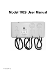
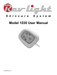
S k i n c a r e
S y s t e m
Model 1029 User Manual
77-I001029 Rev. F
Model 1029 User Manual
TABLE OF CONTENTS
SETUP...............................................................................................................................2
FUNCTION.........................................................................................................................2
TREATMENT.....................................................................................................................3
INDICATIONS FOR USE ..................................................................................................3
CONTRAINDICATIONS.....................................................................................................3
CLEANING.........................................................................................................................4
MAINTENANCE.................................................................................................................4
CLASSIFICATION & SYMBOLS.......................................................................................4
DISINFECTION / STERILIZATION....................................................................................4
SAFETY PRECAUTIONS..................................................................................................4
SPECIFICATIONS.............................................................................................................5
CONTACT INFORMATION...............................................................................................6
APPENDIX A: GUIDANCE AND MANUFACTURER'S DECLARATION - EMC.............7
Page 1
Model 1029 User Manual
SETUP
FUNCTION
Turn the unit on by pressing the black switch on back. The
session timer will display 00. Note: If P or PP appears in the
display it indicates that a pulsator is missing or not connected
correctly. Turn unit off and check pulsator connections.
Page 2
Model 1029 User Manual
TREATMENT
Make sure you read and understand all the information contained in this manual before
operating unit.
1 For: ACNE USE BLUE PULSATOR, PAIN TREATMENTS USE RED or AMBER PULSATORS
and for SKIN TREATMENTS USE RED PULSATORS.
2 Snap on the disposable cover.
3 Set timer: Acne = 20 minutes or Pain / Skin = 10 minutes
4 For ACNE or PAIN TREATMENTS, select Phase II. For SKIN TREATMENT select PHASE I or
II for the first and second treatment and PHASE III for all subsequent treatments.
5 Press the large pulsator button to activate. Start by touching the large pulsator to the skin (
At
no time should the pulsator be brought into contact with the skin surface of the wound area. See
precautions concerning skin contact.) Move pulsator (25% overlap) when beep sounds (every
10 seconds). Problematic acne areas should be treated longer (up to 90 seconds). Continue
treating the area.
For SKIN TREATMENTS, select PAUSE after the area has been treated with the large pulsator.
Remove - dispose of pulsator cover and place large pulsator in holder. Remove the small
pulsator from the cradle and snap on the disposable cover. (Note: squeeze small pulsator cover
before snapping it on the small pulsator for a tighter fit.) Press the small pulsator button to
activate. The beep will sound every 18 seconds to remind you to move from one area to another
covering the crow's feet, under the eyes, on the nose, along side the nose, and by the mouth
Problematic areas should be treated with up to 90 seconds (5 beeps) of LED light therapy over
each area for maximum effect. Besides using a circular motion, vary the movement with zigzag
and straight patterns on the wrinkles and fine lines. If you need more time, press PAUSE and
add minutes to the session timer.
6 When session timer shows “00”, the pulsator turns off, treatment is complete.
7 Remove - dispose of pulsator cover and place pulsator in holder.
INDICATIONS FOR USE
The Model 1029 utilizes Light Emitting Diodes to provide light to the body. Generally indicated to:
- treat dermatological conditions and specifically indicated to treat moderate inflammatory acne
vulgaris (Blue Pulsators);
- provide topical heating to promote increased blood flow, relaxation of muscle and relief of
pain (Amber/Red pulsators)
CONTRAINDICATIONS
Do not use on anyone that is pregnant, has epilepsy or is using any medication that is known
to cause light sensitivity, e.g., tetracycline or Retin-A.
Page 3
Model 1029 User Manual
CLEANING
Cabinet
As required perform the following:
Disconnect the power cord from electrical outlet before cleaning unit / accessories.
Do not use petroleum-based solvents / cleaners. Do not use liquid directly on the unit /
accessories.
Clean cabinet / accessories with mild soap and water applied with a damp cloth - wipe dry.
MAINTENANCE
If the device is observed to not be operating properly, then discontinue use immediately and
contact your distributor for service.
No periodic service / maintenance requirements.
Control unit / pulsators are calibrated. Repairs must be performed by the manufacturer and verified to original
standards. Contact your distributor concerning repair to prevent voiding
the warranty.
When disposing of this device or any accessories, make certain to abide by your local waste
disposal regulations.
CLASSIFICATION & SYMBOLS
IEC
CLASS II EQUIPMENT. This device is Class II Equipment. Protection from electric shock is
60417-5172 achieved by DOUBLE INSULATION
TYPE B APPLIED PART. This device utilizes Type B Applied Parts. Equipment Equipment
IEC
providing a particular degree of protection against electric shock, particularly regarding: 1)
60417-5333
allowable leakage current.
ISO
Caution / Read Instructions for use
7000-0434A
ISO
7010-M002
Follow instructions for use
DISINFECTION / STERILIZATION
No disinfection / sterilization requirements. Read safety precautions concerning skin contact.
SAFETY PRECAUTIONS
Use only GlobTek power supply model GMT21089-1815-T3, REF G1200LCP-Y-MED. Replacement, contact
distributor - request replacement REF 62-0000150.
Page 4
Model 1029 User Manual
To fully isolate the Model 1029 from the supply mains, unplug the AC cord from the power supply.
Only attach accessories specifically provided for use, with the Model 1029. Attaching any accessory or
device not intended to be used with the Model 1029 will compromise safety and may damage the equipment.
The pulsators are intended for direct contact with healthy skin only. Do not place the pulsators directly in
contact with injured or damaged skin surfaces. The light may be applied to injured areas but the pulsators
must be held away from the skin surface.
Do not apply the pulsator directly to the skin when the ambient temperature is above 32 C (90 F).
This device has been tested for EMC compliance with IEC60601-1-2(2007), EN61000-3-2(1995) and
EN61000-3-3(2006). Medical Electrical Equipment needs special precautions regarding EMC. Portable and
mobile RF communications equipment can affect medical electrical equipment. The use of accessories,
transducers, and cables other than those specified by the manufacturer, may result in increased emissions or
decreased immunity of the equipment or system. The equipment or system should not be used adjacent to
or stacked with other equipment and that if adjacent or stacked use is necessary, the equipment or system
should be observed to verify normal operation in the configuration in which is will be used. Should
interference be noted:
- reorient or relocate the equipment.
- increase separation between the equipment.
- connect equipment into a different circuit.
EQUIPMENT NOT SUITABLE for use in the presence of a FLAMMABLE ANESTHETIC MIXTURE WITH AIR
or WITH OXYGEN or NITROUS OXIDE.
Do not shine pulsators directly into the eyes, apply treatment on the upper eye lids or directly over thyroid
gland (center of neck).
Administer only after physician consultation if patient 1) is pregnant, 2) has epilepsy, and 3) taking any
medication that would cause a sensitivity to light such as tetracycline or acutane, 4) any skin conditions that
would be negatively affected by light stimulation.
Indoor use only.
Do not operate near water.
Do not connect pulsators while active - must be in pause mode or turned off.
SPECIFICATIONS
SYSTEM
Movement Guide
Audible Beep: Large/Double Pulsator every 10 seconds; Small Pulsator every 18
seconds
Session Timer
Countdown, 1-99 minutes
Photopulsation Level
PHASE I, II, III each have a weighted group of photomodulation frequencies. Light
power is reduced ≈10% per phase from Phase III.
Frequencies* (Hertz - duration is seconds)
PHASE I - 73Hz-1s, 292Hz-1s, and 584Hz-1s.
PHASE II - 73Hz-2s, and 584Hz-1s.
PHASE III - 73Hz-4s, and 584Hz-1s.
* Frequencies sequentially selected
Page 5
Model 1029 User Manual
Power Supply
Input: 100-240VAC , 50-60Hz @ 1.0A, IEC C14 receptacle. Output:15VDC power
input at 1.2A
GlobTek only, REF 62-00000150
Warranty
Contact distributor for warranty term and coverage.
Expected Service Life
5 years
Environmental
Operating ambient temperature range of +10°C (50°F) to +40°C (104°F)
Operating humidity maximum 95% RH (no condensation)
Operating atmospheric pressure 22.7 inHg to 31.3 inHg (70 kPa to 106kPa)
Operating altitude ≤ 2000m, Pollution degree 2 (office environment)
Shipping / Storage
Dimensions: 61cm (24") x 36cm (14") x 20cm (8")
Weight: 5kg (11 lbs.)
Temperature: -20°C ( -4°F) to 50°C (122°F)
Humidity max.: 95% RH (no condensation)
Pulsators
Treatment area:
Small Pulsator - 1 cm2
Large Pulsator - 9 cm2
Double Pulsator - 19 cm2
Cable
61cm (24") coiled, 1:5 extension ratio
Thermal
Large / double pulsators will elevate skin temperature to
40°C - 45°C (104°F - 113°F).
Small Red
1 LED, 625nm @ 40mW
Phase III - 10mW/cm2
Large (Double) Red
1 (2) LED, 625nm @ 160mW + optics
12 (24) infrared LED, 940nm @ 20 mW
Phase III - 80mW/cm2
Large (Double) Amber
1 (2) LED, 590nm @ 80mW + optics
12 (24) infrared LED, 940nm @ 20 mW
Phase III - 25mW/cm2
Large (Double) 420 Blue
1 (2) LED, 455nm @ 100mW + optics
12 (24) LED, 420nm @ 18 mW
Phase III - 45mW/cm2
CONTACT INFORMATION
RevLight Skincare System
210 Berg Street
Algonquin, IL 60102
Toll Free: (844) 506-6525
www.rev-light.com
Page 6
Model 1029 User Manual
APPENDIX A: GUIDANCE AND MANUFACTURER'S DECLARATION - EMC
Note- Essential Performance: for the purpose of EMC compliance, no device functions are considered essential to the
safety of the user or patient.
Table 1
Guidance and manufacturer’s declaration – electromagnetic emissions
The Model 1029 is intended for use in the electromagnetic environment specified below. The customer or the user of the Model 1029 should assure
that it is used in such an environment
Emissions test
Compliance
RF emissions
CISPR 11
Group 1
RF emissions
CISPR 11
Class B
Harmonic emissions
IEC 61000-3-2
Class A
Voltage fluctuations/
flicker emissions
IEC 61000-3-3
Complies
Electromagnetic environment – guidance
The Model 1029 uses RF energy only for its internal function. Therefore, its RF
emissions are very low and are not likely to cause any interference in nearby
electronic equipment
The Model 1028 is suitable for use in all establishments, including domestic
establishments and those directly connected to the public low-voltage power
supply network that supplies buildings used for domestic purposes.
Table 2
Guidance and manufacturer’s declaration – electromagnetic immunity
The Model 1029 is intended for use in the electromagnetic environment specified below. The customer or the user of the Model 1029 should assure
that it is used in such an environment
IMMUNITY test
Electrostatic
discharge (ESD)
IEC 61000-4-2
IEC 60601 test level
Compliance level
± 6 kV contact
± 6 kV contact per guidance
± 8 kV air
± 8 kV air
Electromagnetic environment – guidance
Floors should be wood, concrete or ceramic tile. If
floors are covered with synthetic material, the relative
humidity should be at least 30 %.
Contact discharge can cause the Model 1029 to turn off
or to become unresponsive and may require manually
restart by cycling power switch. Operation interruption
does not present a hazard in regards to functional
safety and essential performance. Model 1029 tested
device had metal pulsator enclosures and connectors
which were subsequently changed to plastic removing
ESD contact discharge points.
Electrical fast
transient/burst
IEC 61000-4-4
Surge
IEC 61000-4-5
± 2 kV for power supply lines
± 2 kV for power supply lines
per guidance
Mains power quality should be that of a typical
commercial or hospital environment.
± 1 kV for input/output lines
Some electrical fast transient/burst conditions can
cause the Model 1029 to turn off or to become
unresponsive and may require manually restart by
cycling power switch. Operation interruption does not
present a hazard in regards to functional safety and
essential performance. It may be necessary to position
the Model 1029
further from sources electrical fast transients by
connecting it to a different electrical outlet or providing
power line conditioning.
± 1 kV for input/output lines
± 1 kV line(s) to line(s)
± 1 kV line(s) to line(s)
± 2 kV line(s) to earth
± 2 kV line(s) to earth
Page 7
Mains power quality should be that of a typical
commercial or hospital environment.
Model 1029 User Manual
Voltage dips, short
interruptions and voltage
variations on power
supply input lines
IEC 61000-4-11
<5 % UT (>95 % dip in UT) for
0,5 cycle
<5 % UT (>95 % dip in UT) for
0,5 cycle
40 % UT (60 % dip in UT) for 5
cycles
40 % UT (60 % dip in UT) for 5
cycles
70 % UT (30 % dip in UT) for
25 cycles
Power frequency (50/60
Hz) magnetic field
IEC 61000-4-8
Mains power quality should be that of a typical
commercial or hospital environment. If the user of the
Model 1029 requires continued operation during power
mains interruptions, it is recommended that the Model
70 % UT (30 % dip in UT) for 25
1029 be powered from an uninterruptible power supply
cycles
or a battery.
<5 % UT (>95 % dip in UT) for
5s
<5 % UT (>95 % dip in UT) for 5
s
3 A/m
3 A/m
Power frequency magnetic fields should be at levels
characteristic of a typical location in a typical
commercial or hospital environment.
NOTE UT is the a.c. mains voltage prior to application of the test level.
Table 4
Guidance and manufacturer’s declaration – electromagnetic immunity
The Model 1029 is intended for use in the electromagnetic environment specified below. The customer or the user of the Model 1029 should assure
that it is used in such an environment.
IMMUNITY test
IEC 60601 test level
Compliance level
Electromagnetic environment – guidance
Portable and mobile RF communications equipment
should be used no closer to any part of the Model 1029,
including cables, than the recommended separation
distance calculated from the equation applicable to the
frequency of the transmitter.
Recommended separation distance
Conducted RF
IEC 61000-4-6
3 Vrms
150 kHz to 80 MHz
3 Vrms
Radiated RF
IEC 61000-4-3
3 V/m
80 MHz to 2,5 GHz
3 V/m
d = 1,2 √P
d = 1,2 √P
80 MHz to 800 MHz
d = 2,3 √P
800 MHz to 2,5 GHz
where P is the maximum output power rating of the
transmitter in watts (W) according to the transmitter
manufacturer and d is the recommended separation
distance in meters (m).
Field strengths from fixed RF transmitters, as
determined by an electromagnetic site survey,a should
be less than the compliance level in each frequency
range.b
Interference may occur in the vicinity of
equipment marked with the following
symbol:
NOTE 1 At 80 MHz and 800 MHz, the higher frequency range applies.
NOTE 2 These guidelines may not apply in all situations. Electromagnetic propagation is affected by absorption and reflection from structures, objects
and people.
a Field strengths from fixed transmitters, such as base stations for radio (cellular/cordless) telephones and land mobile radios, amateur radio, AM and
FM radio broadcast and TV broadcast cannot be predicted theoretically with accuracy. To assess the electromagnetic environment due to fixed RF
transmitters, an electromagnetic site survey should be considered. If the measured field strength in the location in which the Model 1020 is used
exceeds the applicable RF compliance level above, the Model 1029 should be observed to verify normal operation. If abnormal performance is
observed, additional measures may be necessary, such as re-orienting or relocating the Model 1029.
b Over the frequency range 150 kHz to 80 MHz, field strengths should be less than 3 V/m.
Page 8
Model 1029 User Manual
Table 6
Recommended separation distances between portable and mobile RF communications equipment and the Model 1029
The Model 1029 is intended for use in an electromagnetic environment in which radiated RF disturbances are controlled. The customer or the user of
the Model 1029 can help prevent electromagnetic interference by maintaining a minimum distance between portable and mobile RF communications
equipment (transmitters) and the Model 1029 as recommended below, according to the maximum output power of the communications equipment.
Rated maximum output power
of transmitter
W
Separation distance according to frequency of transmitter
m
150 kHz to 80 MHz
d = 1,2 √P
80 MHz to 800 MHz
d = 1,2 √P
800 MHz to 2,5 GHz
d = 2,3 √P
0,01
0,12
0,12
0,23
0,1
0,38
0,38
0,73
1
1,2
1,2
2,3
10
3,8
3,8
7,3
100
12
12
23
For transmitters rated at a maximum output power not listed above, the recommended separation distance d in meters (m) can be estimated using the
equation applicable to the frequency of the transmitter, where P is the maximum output power rating of the transmitter in watts (W) according to the
transmitter manufacturer.
NOTE 1 At 80 MHz and 800 MHz, the separation distance for the higher frequency range applies.
NOTE 2 These guidelines may not apply in all situations. Electromagnetic propagation is affected by absorption and reflection from structures, objects
and people.
Page 9