1
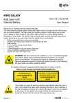
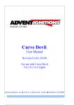
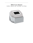
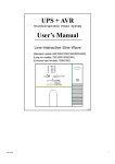
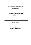
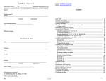
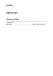
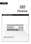
MOONSTAR4 User’s instruction manual This manual contains important information about the safe installation and use of this product Please read this instruction manual carefully before installing or operating Please keep these instructions in a safe place for future reference Introduction Thanks for choosing our laser device, believing this brand new product will bring you unlimited marvel and happiness. Before operating this device, please read this manual thoroughly, and retain it for future reference. CAUTION Please read this manual fully before installing or operating this product as it contains important safety information relating to its installation and operation. This Class 3B laser product emits hazardous levels of optical radiation and will cause injury to the eyes if viewed directly. This product is not suitable for projection directly at audiences or other personnel. This product must not be used for any form of audience scanning application and is for professional use only. Important information This product is a Class 3B laser and should only be installed and used by personal who are trained in the management of laser radiation and are able to operate in accordance within the guidance given by the Health and Safety Executive (HSE) in HS(G)95: “The Radiation Safety of Lasers used for Display purposes”. This product contains no user-serviceable parts. Under no circumstances should any attempt be made by the user to dismantle or modify it in any way. Installation instructions This product must be securely mounted with adequate fixings to hold the weight. If mounted at height, use a safety wire attached to the eyebolt and a secondary fixing point. Position the aperture so that its emission is always directed away from people and objects that are able to reflect the emission towards people. In this regard the separation distances of 3 metres vertically and 2.5 metres horizontally, cited in HS(G)95 and shown below must be observed. Vertical bird’s eye view Vertical cross sectional view Unpacking Please check the contents to ensure that the product has been received in good condition. Laser x 1 unit IEC Power Lead x 1pc I.R. remote control x1 pc Safety Keys x2pcs If you find any accessory is missing or the product has arrived with any problems, please contact your retailer at once. This product contains no user-serviceable parts so make no attempt to try to fix or modify this item yourself as this will invalidate the warranty. We recommend you keep the original package and proof of purchase for any possible replacement or returned demand. Setting up 1. Unpack the laser ensuring all packaging and tape is removed. 2. Always test the laser before fixing in a permanent location. 3. Connect the IEC mains plug and switch the rear power switch on. 4. Insert the safety key and turn to a quarter turn clockwise. At this point ensure that no one is exposed to laser radiation. 5. Select which mode you want to operate the laser in. 6. Leave the laser to run for 10 minutes before installing in its location. Installation When mounting at height, attach a safety wire to the eyebolt with an independent fixing. Use the integral mounting bracket with a suitable clamp for stand or truss being fixed to. When mounting directly to ceiling surfaces, be sure to use adequate fixings for the supporting material. Connecting to mains, earth wire (ground) must be connected. Use the supplied IEC lead to connect to the main power supply as follows: Wire Brown Blue Yellow/Cyan Connection Live Neutral Earth International symbol L N For your safety, please kindly pay attention to all of the warnings below: Always plug in the power plug last and disconnect from the mains when the device is not in use or before cleaning. Do not install and operate the device in rain or extreme heat, moisture or dusty environments. This device is for indoor use only and in a dry environment. Do not switch on immediately. Wait until the unit reaches room temperature. Do not shake the device and avoid brute force when installing or operating. Do not use the device during thunderstorms and please disconnect the power. Do not use solvents or aggressive detergent to clean the device. Use a soft and clean cloth. Do not modify the device or the connected power cord without authorisation. Do not stare into the aperture. This product emits hazardous levels of optical radiation and will cause serious injury to the eyes if viewed at close range. This product should be securely mounted so that its output emission is always directed away from people and at objects that are able to reflect emission towards people. In this regard, the separation distances cited in HS(G)95 should be observed. The symbol determines the minimum distance from lighted objects. The minimum distance between light-output and the illuminated surface must be more than 0.5m. Replacing the fuse First disconnect from the mains power supply then remove the fuse holder above the IEC Socket to reveal the fuse. Replace with the correct fuse rating as stated on the product or in the user manual. Then lock the fuse holder cover back into place. General maintenance Be sure to power off the fixture before conducting maintenance. To maintain optimum performance and minimize wear, fixtures should be cleaned frequently. Usage and environment are contributing factors in determining frequency. As a general rule, fixtures should be cleaned at least twice a month. Dust build-up reduces light output & performance as well as overheating. This can lead to reduced life and increased mechanical wear. Unplug fixture from power. Use a vacuum or air compressor and a soft brush to remove dust collected on external vents and internal components. Clean all glass when fixture is cold with a mild solution to the cloth or tissue, and drag dirt and grime to the outside of the lens. Gently polish optical surfaces until they are free of haze and lint. The cleaning of internal and external optical lenses and/or mirrors must be carried out periodically to optimize light output. Cleaning frequently depends on the environment in which the fixture operates: damp, smoky or particularly dirty surroundings can require cleaning fluid. Always dry the parts carefully. Clean the external optics at least every 20 days. Front panel 1. Laser aperture 2. LED aperture 3. Power LED 4. I.R. remote receiver 5. Music LED Rear Panel 6. DMX input 7. DMX output 8. Remote power connector 9. Safety eyebolt 10. Safety lock 11.Contorl panel 12.Internal microphone 13.Sensitivity 14.Cool fan 15.IEC mains inlet 16.Mains fuse holder 17.Power switch Control panel Press MODE to navigate through the options The control panel and display allow the user to adjust settings as follows… Press ENTER to select an option and adjust value using UP and DOWN buttons Press ENTER again to confirm setting Control panel options Display Aut Mode Automatic mode AutS Automatic slow mode RDNM Auto Shuffle play Soud Sound activated mode RGBS LED FDES d001 DMX start address SLAU Slave mode Press ENT for setting(press MODE to exit) R0——R9 Red LED: brightness:weak-strong G0——G9 Green LED: brightness:weak-strong B0——B9 Blue LED: brightness:weak-strong SR0—SR9 LED strobe: slow -fast SP0—SP9 LED gradual change:slow -fast Press ENT for setting(press MODE to exit) REM0 REMX REM1 REM2 Automatic mode Sound activated mode Manual mode Stand-alone modes THE laser can operate in stand-alone mode one of 3 ways: Auto or Sound-activated Automatic fast Show / / Stand Alone mode (Auto) 1 Press the function button (MODE) to enter Mode options 2 Press the function button until the LED panel shows Auto 3 Press the Enter button to confirm the setting The laser will now be working in Automatic fast / Stand Alone mode Automatic slow Show / Stand Alone mode (Auto) 1 Press the function button (MODE) to enter Mode options 2 Press the function button until the LED panel shows Auto 3 Press the Enter button to confirm the setting The laser will now be working in Automatic slow / Stand Alone mode Sound Activated / Sound-to-Light / Stand Alone mode (Sound) 1 Press the function button (MODE) to enter Mode options 2 Press the function button until the LED panel shows Sound 3 Press the Enter button to confirm the setting The laser will now be working in Sound Activated Color mode / manual setting mode (color) 1 Press the function button (MODE) to enter Mode options 2 Press the function button until the LED panel shows color 3 In color mode press ENT into manual setting submenu, setting parameter manually to set the display effect. Pressing ENT into next setting till all finished then go back to home menu. DMX mode 1 Press the function button (mode) to enter Mode options 2 Press the function button until the LED panel shows d001 3 Press the Enter button to confirm the setting or change the address using the Up and Down buttons 4 Press the ENT button to confirm the setting The laser will now be working in DMX mod DMX mode / DMX address setting 1 Ensure the unit is in DMX mode (see above) 2 Press the Up or Down buttons to adjust the DMX address 3 Press the Enter button to confirm the setting If multiple connected units are to be controlled in exactly the same way, set all units to the same starting address (e.g. 001). If individual control of multiple connected units is required, each unit must have its own starting address. This address must be at least 10 channels apart e.g. set the first unit to 001 and the second unit to 011, the third unit to 021 and so on. The DMX controller will now control all the connected units separately. Master/Slave mode 1 Press the function button (MODE) to enter Mode options 2 Press the function button until the LED panel shows SLA 3 Press the Enter button to confirm the setting The laser will now be working in Slave mode To create a Master/Slave chain of units, one laser has to be designated as the Master unit whilst the remaining units have to be set as Slave units. To set the Master unit, choose one laser and set it to your desired mode (Auto mode, Sound-to-Light mode, etc). Next connect all other units via DMX cables. To achieve this, join the DMX output of one unit to the next unit’s DMX input until all lasers are connected. Set all the Slave units to Slave mode (see above). The Slave lasers will now duplicate the actions of the Master unit. Microphone sensitivity In sound-activated mode, the sensitivity of the internal microphone can be adjusted via the control panel. To set the sensitivity level, do the following… Remote control mode The laser can be operated using the supplied handheld infra-red remote control. To use this remote control, firstly, remove the plastic tab at the bottom of the remote to activate the internal battery. If necessary, this can be replaced with a standard CR2025 button cell. A B C D/F E G H I J/K The A is red laser strobing, use the 0-8 digit buttons to choose strobing speed,0 is close,9 is lighting; The B is LED strobing; use the 0-8 digit buttons to choose strobing speed,0 is close;9 is lighting ; The C is the speed of the motor; use the 0-9 digit buttons to choose speed, Color buttons Press buttons to cycle through laser’s/LED’s available color; Pause button Press button to pause the laser effect; Auto mode Press button to activate Auto mode, First press is AUTO fast,second press is AUTO slow Music mode Press button to activate Sound-to-Light mode On/Off button Press button to activate turn theSound-to-Light laser on and mode off Fruitless Keys; DMX MODE The laser is equipped with 3-pin XLR connectors for DMX input and oThese connectors are wired in parallel. Only use a shielded twisted-pair cable designed for 3-pin XLR-plugs and connectors in order to connect the controller with the fixture or one fixture with another. Caution: At the last fixture, the DMX-cable has to end with a terminator. Solder a 120 Ohm resistor between PIN 2 (-) and PIN 3 (+) into a 3-pin XLR-plug and plug it in the DMX-output of the last fixture. DMX parameters CHANNEL CH 1 CONTROL MODE CH2 COLOR SELECTION CH3 STROBING CH4 ROTATION1 CH 5 LASER VIBRATE CH6 LASER TWINKLING CH 7 RED LED CH 8 GREEN LED CH9 BLUE LED CH10 LED DIM CH11 LED STROBE CH12 LED ROTATE DMX 000-049 050-99 100-149 150-199 200-255 000-004 005-028 029-056 057-084 085-112 113-140 141-168 169-197 198-224 225-255 000-004 005-249 250-255 000-004 005-127 128-133 134-255 000-004 CONTROL DMX MODE Automatic slow Automatic fast Sound mode Shuffle play Black out Red on Green on Red on & Green on Green strobing Red strobing Red on & Green strobing Red strobing & Green on Red & Green strobing Red & Green(alternate strobing) No function Strobing (show-fast) Strobing to sound No rotation Clockwise rotation(slow-fast) Stop Counterclockwise rotation (slow-fast) No Function 005-255 Vibrate 000-255 Twinkling:slow-fast 000-127 128-169 170-209 210-255 000-127 128-169 170-209 210-255 000-127 128-169 170-209 210-255 RED LED lighting LED brightness 0%-100% LED brightness 100%-0% LED brightness 100%-0%-100% GREEN LED lighting LED brightness 0%-100% LED brightness 100%-0% LED brightness 100%-0%-100% BLUE LED lighting LED brightness 0%-100% LED brightness 100%-0% LED brightness 100%-0%-100% 000-255 LED DIMMER 000-004 005-249 No strobe Strobe:slow-fast 250-255 Strobing to sound 000-004 No rotation 005-127 Clockwise rotation(slow-fast) 128-133 Stop 134-255 Counterclockwise rotation (slow-fast) :slow-fast Specifications Model MOONSTAR4 Power supply 100-240Vac, Power consumption 20W Fuse rating T1A 250V(20mm glass) Red laser power 100mw 650nm Green laser power 50mw 532nm Laser class 3R Blue LED power 455nm 3W Amber LED power 600nm 3W White led POWER 6500K 3W Operating temperature range 10-40 DMX connection 3-pin XLR DMX channels 1-10 Remote control battery CR2025 button cell Dimensions 225×185×80mm Net Weight 2 kgs 50/60Hz(IEC) ℃ Important: This product conformed to Laser & LED Safety standard BSEN60825-1 2007 incorporating corrigendum 2008 Disposal: The “Crossed Wheelie Bin” symbol on the product means that the product is and should not be disposed with other household or commercial waste at the end of its classed as Electrical or Electronic equipment useful life.