1
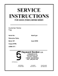
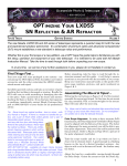
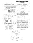
OK basic user manual with OK safety and operation instructions, general maintenance
and troubleshooting concerns, and a partial list of replacement parts. The manual
could be improved greatly through the use of pictures showing operational steps and
illustrating precautions, and greater detail in the operational steps and
troubleshooting (which are likely so general due to the lack of operating
experience.)
Soil Mixer and Dispenser
User’s Manual
Ohio University
Russ College of Engineering
Mechanical Engineering Senior Design Team: Keeping M.E. Fertile
Authors: Matthew Haszto, Patrick Bonifas, Zakary Sherfy, Michael Brennan, Nicholas
Randolph
Assembly and Subassemblies
F2
F1
F3 x 3
F7 x 2
R1
F4 x 3
B1 x 2
F6 x 3
F5 x 2
W1 x 2
W2 x 2
F1 - Steel Angle (2x2x69 inches)
F6 - Steel Angle (2x2x21 inches)
F2 - Steel Angle (2x2x10 inches)
F7 - Steel Angle (2x2x21 inches)
F3 - Steel Angle (2x2x33 inches)
W1 - 8 inch pneumatic tires
F4 - Steel Angle (2x2x16 inches)
W2 - 8 inch pneumatic tires with casters
F5 - Steel Angle (2x2x22 inches)
R1 - Rear axel
H1
A1
P1
VB1
M1
P2
H1 – Hopper
A1 – Auger Shaft with 8 paddles
P1 – Auger Shaft Pulley
P2 – Auger Shaft Pulley (1/2 of P1)
VB1 – Linked V-Belt
G1 – Gearbox, 40 to 1 ratio
AC1 – AC motor (located behind gearbox)
M1 – Motor mount
G1,
AC1
Safety and Precautions
During Operation
-
-
Do not reach inside the machine while it is running for any reason. Ensure that the
machine comes to a full stop before placing body parts or other equipment in the
machine.
Do not wear loose clothing or let loose hair dangle near the machine while
performing work. Loose objects can easily become caught.
Ensure hopper is clear of all foreign objects or debris prior to operation.
Ensure that all items are removed from the grate prior to opening or shutting the
grate. Failure to do so could cause equipment to be caught in machine.
Use only specified soil, using other mixtures such as gravel could form dangerous
projectiles during operation.
Ensure that weight placed on grate does not exceed tolerance specified. Exceeding
the weight limit could cause grate bending and catastrophic failure.
Ensure that wheel breaks are locked during operation. Failure to do so could cause
machine to move in operation.
Ensure that cord is outside the work area to avoid tripping hazard.
It is advisable to wear safety glasses while operating the machine to prevent dust
and debris from entering eyes.
Do not lean or otherwise place large amounts of pressure against the side of the
machine. Bending/Tipping over will cause catastrophic failure
If grinding, rattling or shaking of machine occurs outside normal parameters,
SHUT MACHINE DOWN IMMEDIATELY.
Storage
-
Always store machine on level surface and lock wheels. Failure to do so could
cause machine to move unexpectedly.
Ensure that sharp corners are placed outside walk path to keep them from hurting
people or damaging equipment that may bump into it.
Do not place anywhere machine can be hit or knocked over by the movement of
other equipment.
Properly wind and store cord to avoid tripping hazard.
Do not store equipment on top of grate.
Keep small equipment capable of falling into machine clear of area. Small parts in
machine can damage it.
Movement
-
Make sure that you have clear line of site prior to moving machine. Machine is
heavy and can cause harm to individuals hit with it.
Do not let children or weak persons to move machine. Machine could potentially
harm user if not properly controlled.
Do not move over grade with at least two people to control machine. Machine
could potentially roll out of control.
Only push or pull using the specified handles, Pushing at improper places can
cause machine to tip over.
Ensure machine is unplugged prior to movement and cord is properly wound in
order to remove tripping hazard.
Operation Instructions
Before operation a set of checks should be performed to ensure a safe start-up. A list of
the checks is shown below.
a) Make sure there is nothing but soil in the hopper. Rocks, sticks, or other foreign objects
could cause a jam and damage the auger or lift system.
b) Position the casters to reduce the chance of tripping (i.e. so they are not pointing straight
out) and lock both wheels. This prevents the machine from shifting during operation.
c) Make sure the grate is properly positioned in the lip. Improper seating will cause the
safety switch to cut power to the motor.
After performing the pre-operation checks the machine is then ready for use. The
following is a list of steps to take for start-up and operation.
1.) Plug the cord into the nearest available outlet. Extension cords can be used but it is
recommended to use heavy duty extension cords to deal with the current drawn by the
motor.
2.) Fill the hopper with the desired amount of soil and water. When finished replace the top
grate.
3.) Press START button.
4.) Soil should begin to come out of the lift system and the user can now fill containers.
Maintenance
Component
Required Service/Inspection
Maintenance
Schedule
V-belt
check tension of belt, signs of
wear
monthly
Lift Belt
inspect tension, alignment, check
for signs of wear
bi-weekly
Bolts
Check bolts for tightness
monthly
Rust/Corrosio
n
empty machine/ inspect machine
for signs of corrosion
montly
Tires
check wear and tire pressure
monthly
Bearings
inspect, clean + regrease
bearings, inspect set screws
quarterly
Motor/Power
Transmission
See motor manual
motor housing
remove motor housing to vacuum
motor, power transmission
system
buckets
check bolts for tightness/buckets
for signs of wear
See Motor
Manual
Possible Required
Maintenance
Refer to
section
XX
tighten/replace vbelt/adjust
transmission
pulleys
tighten/align lift
belt
tighten bolts
remove rust/ apply
rust preventative
material
inflate to correct
psi/ replace tires
tighten set screws/
replace bearings
change motor
brushes, etc
monthly
quarterly
tighten
bolts/replace
bucket
*Caution: turn off and unplug device before performing any maintenance tasks such as
cleaning
Troubleshooting
CAUTION: When troubleshooting, turn off the power and unplug the power cord.
Problems
Solutions
Check if power cord is plugged in
Motor Not Running
Check if the power cord leads are
connected to motor
Check if the hopper cover is on the
kill switch
It could be off the
pulleys
Check the power transmission belt.
It could be broken
Check the tension of
the belt
Auger is Not Moving,
When Motor is Running
Check if the motor shaft is inserted
into the gearbox correctly
Hopper may be overfilled. After
checking the power transmission belt
and gearbox, remove some soil from
the hopper.
Check the tension of
the belt
Check the lift system belt
Soil Not Dispensing
When Auger is Moving
It could be damaged
or broken
Check if buckets are broken
Hopper may be overfilled. Overfilled
hopper may be causing the lift system
to be running at a slower speed than
required. Remove some soil from the
hopper.
Hopper Cover Kill
Switch Not Working
It could be off the
pulleys
Check if the wire leads are connected
properly
Check if the hopper cover is on the
kill switch
Replacement Parts Chart and Details
Replacement Parts Chart and Details
PART NAME:
Motor Gearbox
Motor Base Mount
Elecrtic Motor
Belt for Motor Pulley
DESCRIPTION:
QTY.
GEARBOX,40.50:1,56C INPUT,1.25"OUTPUT SHAFT DIA.
1
1750 RPM INPUT=43.21 OUTPUT RPM
BASE MOUNT/FEET FOR ABOVE UNIT
REMOVE C-FLANGE ON GEARBOX AND MOUNT NEW
BASE
LEESON MOTOR,1.5HP,1750 RPM,56C FRAME, MAN.O/L
1
1
1/60/115-208-230 VAC,TEFC, FOOTLESS
B POWERTWIST BELTING, 2M (6.6FT.) SLEEVE
1
2 GROOVE PULLEY, 6.95" O.D. TAPER LOCK
1
TAPER LOCK BUSHING,1-1/4", For Gearbox
1
2 GROOVE PULLEY, 3.75" O.D. TAPER LOCK
1
TAPER LOCK BUSHING, 3/4", For Auger
1
3" x 2" CC-HD Poly Blue Elevator Buckets (Standard Drilling)
TBD
¼” x 1-1/2” Zinc Plated Fanged Elevator Bolts
TBD
Washers for Elevator Buckets
Zinc Plated Flat Washer
TBD
Nuts for Elevator Buckets
Zinc Plated Nylock Nuts
TBD
Start/Stop Switch
A-B 100-C09D10 MCS-C CNTCTR IEC 9A 110V 50HZ/
1
Power Box for On/Off Switch
A-B 800S-2SA STATION ASSMBLD P/B 600VAC MAX 5
1
Pillow Block Bearings for
Auger Shaft
Stamped Steel Base Mounted Ball Bearing, Double Sealed,
2
3/4" Diameter Shaft and 1" Center Height
8" Pneumatic Wheel Only, Zinc Plated, with Black Inflatable
Tire
8" Pneumatic Swivel Caster with TB Brake, Zinc Plated,
2
Pulley for Gearbox
Pulley for Auger Shaft
Buckets for Elevator Lift
System
Bolts for Elevator Buckets
Stationary Pneumatic Wheels
Swivel Caster Pneumatic
Wheels
2
with Black Inflatable Tire
Kill Switch for Hopper Grate
1
Belt for Elevator Lift System
1