1
US008228039B2
(12) United States Patent
(10) Patent No.:
Takeno et al.
US 8,228,039 B2
(45) Date of Patent:
(54)
BATTERY
TESTING METHOD
TESTING DEVICE AND BATTERY
(75)
Inventors: Kazuhlko Takeno,Yokohama (JP);
_
Jul. 24, 2012
JP
2003-9406
1/2003
JP
2003-282150
10/2003
JP
2007_292654
11/2007
Takayukl Kanal, Yokohama (JP);
Haruo Uemura, Kita-ku (JP)
OTHER PUBLICATIONS
Matsushima et al., Residual Capacity Estimation of Stationary
Lithium-ion Secondary Cells in Telecommunications Systems Using
(73) Assignee: NTT DoCoMo, Inc., Tokyo (JP)
a Brief Discharge, 28th Annual International Telecommunications
(*)
Notice:
Subject to any disclaimer, the term of this
patent is extended or adjusted under 35
Energy Conference, pp. 1-7, Sep. 2006*
R. Dueber, Tests Prove the Safety of Silver-Zinc Battery Technology
U.S.C. l54(b) by 439 days.
over Lithium-Ion, pp. 1-9, dated Jul. 2007.*
(Continued)
(21) App1.No.: 12/335,944
Primary Examiner * Melissa Koval
(22) Filed:
Dec. 16, 2008
(65)
Assistant Examiner * Daniel Miller
(74) Attorney,
Prior Publication Data
US 2009/0160403 A1
(30)
Jun. 25, 2009
or
Firm * Oblon,
Spivak,
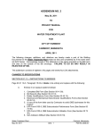
(57)
ABSTRACT
The present invention applies load to a portable telephone by
charging and discharging a secondary battery conforming to
Foreign Application Priority Data
Dec. 19,2007
Agent,
McClelland, Maier & Neustadt, L.L.P.
(JP) ............................... .. 2007-327661
the actual Way of use of the portable telephone, so that the
performance of the secondary battery in a portable telephone
(51)
Int. Cl.
H02] 7/00
References Cited
connected for charging can be accurately tested. A battery
testing device of the present invention has: a charge control
circuit for controlling input poWer Which is input to a lithium
ion battery via an AC adapter; and a radio circuit for control
ling output poWer Which is output from the lithium ion battery
and discharging the lithium ion battery, Wherein When the
lithium ion battery reaches a fully charged state, the radio
circuit starts discharging While the charge control circuit
U.S. PATENT DOCUMENTS
and When the lithium ion battery reaches a predetermined
(2006.01)
(52)
US. Cl. ..................................................... .. 320/136
(58)
Field of Classi?cation Search ................ .. 320/ 124,
320/l27il36; 324/427
See application ?le for complete search history.
(56)
stops charge of the lithium ion battery using the AC adapter,
2007/0145949
Al*
6/2007
Matsushima etal.
....... ..
320/132
lithium ion battery using the AC adapter While the radio
circuit stops discharge of the lithium ion battery.
FOREIGN PATENT DOCUMENTS
CN
200972879 Y
ll/2007
JP
8-136600
5/1996
6 Claims, 12 Drawing Sheets
21
+ L
W
charged
state, the charge
control circuit starts charge
of the
_
_
_
_
_
_
22
C
2s
in
Von
V2a
24
V2b l,
/ _Q,
v3
Vg {
CONSTANT
(ax/‘59E
VOLTAGE I
7
vb +
CONTROL V
6
VOLTAGE DETECTION 1 2a
VOLTAGE DETECT|ON1 vzb
3
%\ 4
_
2
5
US 8,228,039 B2
Page 2
OTHER PUBLICATIONS
Kim et al., Analysis of Heat Dissipation in Li-Ion Cells & Modules
for Modeling of Thermal Runaway, The 3rd International Sympo
sium on Large Lithium Ion Battery Technology and Application, pp.
1-29, May 2007.*
KoZuka et al., Development of on-line battery testing technology,
19th International Telecommunications Energy Conference, pp. 397
402, Oct. 1997.*
Tsujikawa et al., Development of VRLA battery capacity estimation
system, 29th International Telecommunications Energy Conference,
pp. 788-793, Oct. 2007.*
BT2000 Custom-Designed Multi-Channel Battery Testing System,
available at http://web.archive.org/web/20070508072210/http://
arbin.com/Download/products/bt2000.pdf on Oct. 24, 2007.*
Arbin-010 MITS Pro 4.0-BT2000 User Manual, available at http://
T. Guena, et al., “How Depth of Discharge Affects the Cycle Life of
Lithium-Metal-Polymer Batteries”, Annual International Telecom
munications Energy Conference, 28”’,IEEE, XP31020314, Sep. 1,
2006, pp. 1-8.
Masahiro Ichimura, et al., “Synergistic Effect of Charge/Discharge
Cycle and Storage in Degradation of Lithium-ion Batteries for
Mobile Phones”, Telecommunications Conference, XP31063288,
Sep. 1, 2005, pp. 245-250.
Isidor Buchmann, “Choosing a Battery that will Last. Cycle Life of
Various Battery Systems”, Battery Conference on Applications and
Advances IEEE, XP10352795, Jan. 12, 1999, pp. 365-368.
KaZuhiko Takeno, et al., “Quick testing of batteries in lithium-ion
battery packs with impedance-measuring technology”, Journal of
web.archive.org/web/20070508082125/http://arbin.com/Download/
Power Sources, vol. 128, XP4493641, Mar. 29, 2004, pp. 67-75.
Of?ce Action issued Jan. 27, 2011, in China Patent Application No.
support/MITSPro4.0-BT2000.pdf on Oct. 24, 2007.*
200810185663.X (with English translation).
Guena et al., How Depth of Discharge Affects the Cycle Life of
Lithium-Metal-Polymer Batteries, 28th Annual International Tele
communications Energy Conference, 2006, INTELEC ’06, pp. 1-8,
No. 2007-327661 (with English-language translation).
Sep. 2006.*
Extended European Search Report issued Nov. 4, 2010, in Patent
Application No. 081719114.
T.L. Chern, et al., “The Research of Smart Li-ion Battery Manage
Of?ce Action issued Jun. 29, 201 1, in Korean Patent Application No.
Chinese Of?ceAction issuedFeb. 13, 2012, in Patent Application No.
ment System”, Second IEEE Conference on Industrial Electronics
Korean Of?ce Action mailed Apr. 20, 2012 in Japanese Patent Appli
and Applications, XP31137752, May 1, 2007, pp. 2273-2277.
KaZuhiko Takeno, et al., “In?uence of cycle capacity deterioration
cation No. 10-2008-0127801 (with English translation).
and storage capacity deterioration on Li-ion batteries used in mobile
cation No. 10-2008-0127801 (with corrected English translation).
phones”, Journal of Power Sources, vol. 142, No. 1-2, XP4812984,
Mar. 24, 2005, pp. 298-305.
* cited by examiner
Japanese Of?ce Action issued Oct. 25, 2011, in Patent Application
10-2008-0127801 (with English-language translation).
200810185663.X (with English-language translation).
Korean Of?ce Action mailed Mar. 31, 2012 in Japanese Patent Appli
US. Patent
Jul. 24, 2012
Sheet 2 0f 12
US 8,228,039 B2
Fig.2
BATTERY VOLTAGE (v)
A
CHARGE
i DISCHARGE i
CHARGE
4.2V
CHARGE
AMOUNT
(100%)
CHARGE
4.0V ________________ __€_E _________ H ‘‘‘‘‘ --: ________________ "Irhhv t rt
AMOUNT
(95%)
I
a
a
,
I
Sa
10 MINUTES}? 6 MINUTES T10 MINUTES “5
OPERAVTION TIME
US. Patent
Jul. 24, 2012
Sheet 3 0f 12
US 8,228,039 B2
9
W
m
m.
m
u
mm
\
mm5%a5?2a
\mm iéwlz?
mwHzQornEm ?
mat
"O_0<m“zO_
n
m,
m2:.5v:ma /E0 Jmm5E0w1CN1m6/E vom“
32m
M2%.M3235
US. Patent
Jul. 24, 2012
Sheet 4 0f 12
US 8,228,039 B2
w
O
,
_
_
-.Ne8“5.->.
m
@050
kmwoa/‘zIEi8wo_5a
mm:. _
\J!\__
t39.w,->
m
_Q
A
n_
20.U%
n
H
Pa
m
n
Q>
,1
Q “mo0
2
o.2
o
‘at
mm
mm
US. Patent
5M8260
Qat
Jul. 24, 2012
imoa/‘I102%
@050
Sheet 6 0f 12
US 8,228,039 B2
US. Patent
Jul. 24, 2012
Sheet 7 0f 12
US 8,228,039 B2
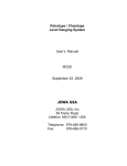
Fig. 7
100--~ ---------------------------------------------------
-
DETERI
AMOUNQRATION
DETERIORATION
AMOUNT
DETERIORATION
AMOUNT
BODEATRIGFEYON
(TCOYAEFSPN%FCILERT)GY
5O
0
_
_
A
_
_
_
_
_
:
_
_
_
_
_
_
_
_
_
_
_
_
_
_
_
_
_
_
_
_
V
_
_
_
_
_
_
_
_
_
_
_
_
_
_
_
_
_
_
_
_
_
_
_
_
_
TEST AT 50°C
_
E
1
_.
:
6
120
MINUTES
MINUTES
(5%)
(100%)
r
OPERATION FREQUENCY
(DEPTH OF DISCHARGE DOD (%))
>
US. Patent
Jul. 24, 2012
Sheet 8 0f 12
US 8,228,039 B2
Fig.8
CHARGE
i DISCHARGE 5
4.2V
Vb
4.0V
---------------
---------------
---------------- "gm-Wan
w
v
EOPETQATION TIME
100%
Qb
95%
OPEVRATION TIME
US. Patent
Jul. 24, 2012
Sheet 9 0f 12
US 8,228,039 B2
Fig.9
%)
v
100 ------------
------------
------------
____________
TODBETARGIFEOYN COYAFPENFSLIRTEY
2O
3O
4'0
BATTERY TEMPERATURE (°c)
50
US. Patent
Jul. 24, 2012
Sheet 10 0f 12
US 8,228,039 B2
Fig. 10
(OTSEMPRFAIUNG DATEJM°UPVSRICN)5IT(E0MNPO°RSACUTE)L
200
-------------------------------------------------------------- -
150
--------------- --Q
\
~
THREE HOURS
100
------------------------------------------------------------- -—
01 O
\ START OF HEATING UP TO 150°C
WHEN BATTERY CAPACITY REACHES
PREDETERMINED CAPACITY
O
0
1
2
TESTING TIME (HOURS)
3
'
US. Patent
Jul. 24, 2012
Sheet 11 or 12
US 8,228,039 B2
Fig. 11
*a
>_ 5,
[I
100
UNUSED
BATTERY
-----------------------------
|_ A
Egg
m
< L_|JJ —
5°,
i
E
-----------------------
II
l1
i
i
75%
DETERIORATION
i
u. 0 uJ
I
O >' m
:
‘
i
.
O3
i
5
C2) B l-
i
i
55%
Q-
9 >' E
50%
50
; DETERIORATION
--------------------------------- -+ ---------------------- Hi“
0! l-IJ E
i
:
E g ,_
LL] (1)
a
i
E
EH '-
‘
25%
[I LU
I
0 LL 3:1
2
:
DETERIORATION
HJJ < 2
E
m
(D O
E E?
2
I
LLl < v
:
:
Q 3(ZERO
YEARS
s
E
ONE
YEAR
TWO
YEARS
TESTING TIME
US. Patent
Jul. 24, 2012
Sheet 12 01 12
US 8,228,039 B2
Fig. 12
21
6P52m3%wQE2o<zr5Em> 6i5wmza/0E_no;im8kv
s
m
n
m
0
-
E
_
“
n
t
"TE
/;
E
n
O
"\
1.
n
T
u
A
mMK
qoqRm
,1u“ EEA___A
E
n.
n
u
R
M
-3RD;H
uc
_
__
EEEA__
E__.H
HMT
HMG;
n“1WPBt
l RM
n“? Ymw__
Nml
(H_HGCN
"n“BDTS(-"1_ ETE
“m
)n“sTw oCEW
TE;
n"“0OUAR
TAM
RsnW“ mmmn
“u.nPB)
UR".
n"“UU12RY“.n"hRPPE);
TAEN__Ti_
BE
S
C
__
n
_
“m
SWA
__
n
L
_
O
\mm)
0
YA
___H
a
mum
%1
m
2
US 8,228,039 B2
1
2
BATTERY TESTING DEVICE AND BATTERY
TESTING METHOD
mance is exhibited in this conventional battery performance
test, and the performance of the secondary battery cannot be
evaluated accurately.
BACKGROUND OF THE INVENTION
SUMMARY OF THE INVENTION
1. Field of the Invention
The present invention relates to a battery testing device and
With the foregoing in vieW, it is an object of the present
invention to provide a battery testing device and battery test
a battery testing method for testing a chargeable secondary
battery by applying a load, by performing charging using a
charging means to charge the secondary battery and discharg
ing of this secondary battery.
ing method for testing the performance of the secondary
battery in a portable telephone being connected for charging,
by applying a load of performing charge and discharge of the
2. Related Background Art
As a multimedia function (eg transmission/reception of
mail and vieWing TV) of portable telephones, there is a format
to use a portable telephone While simultaneously being
portable telephone.
recharged by connecting a charger (that is, and AC adapter) as
means for charging the secondary battery, the device com
shoWn in FIG. 1 in order to enable lengthy use of the portable
telephone. FIG. 1 is a block diagram depicting a state When an
prising: input control means for controlling the input poWer
Which the charging means inputs to the secondary battery;
AC adapter 91 is connected to a portable telephone 90. The
secondary battery conforming to the actual Way of use of the
To achieve the above object, a battery test device according
to the present invention is a battery testing device Which can
charge a chargeable secondary battery by using charging
20
supply 99. A portable telephone 90 encloses a lithium ion
battery 92 as a secondary battery pack, a charge control circuit
93, and a radio circuit 94 as a load device to discharge the
battery, in many cases.
reaches a fully charged state, the output control means starts
25
Which occurs depending on the state of use of the electronic
30
decreases (that is capacity deterioration of the battery) or the
thermal stability of the materials inside the battery (that is
active materials) drops, the thermo-runaWay easily occurs
When the temperature inside the battery becomes high.
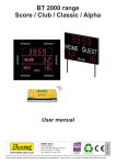
For example, in a case of using a portable telephone 90
While being charged by being connected to an AC adapter, as
mentioned above, charge and discharge are repeated in a
highly charged state Where the voltage is in about a 4.0 V to
35
40
45
50
and charge is restarted When [the battery voltage] reaches the
recharge start voltage Vstart (eg about 4.0 V in FIG. 2), and
this cycle is repeated.
55
of 95% of battery capacity in the fully charged state, capacity
quickly. Hence performance of the secondary battery can be
accurately evaluated in a shorter time.
60
It is preferable that [the battery testing device] further has
65
temperature adjustment means for adjusting the temperature
of the secondary battery, Wherein the input control means
controls the input poWer Which is input to the secondary
battery at a temperature adjusted by the temperature adjust
ment means, using the charging means, and the output control
in Japanese Patent Application Laid-Open No. H8-l36600,
for example.
not considered, therefore a better result than actual perfor
are repeated in the fully charged state and highly charged state
deterioration of the secondary battery progresses more
performance test is performed by using a test device disclosed
HoWever in this conventional battery performance test, the
actual case of using a portable telephone While being charged
by being connected to anAC adapter, as mentioned above, is
evaluated.
It is preferable that the output control means discharges the
secondary battery until reaching a state of 95% of battery
a complete charge (that is a 100% charge) are regarded as one
cycle, and a test to evaluate the performance of the secondary
battery is performed by repeating this cycle. This battery
forming to the actual Way of use of the portable telephone,
such as using the portable telephone While being connected to
such charging means as an AC adapter for charging, thereby
capacity in fully charged state When the secondary battery
reaches the fully charged state. Since charge and discharge
Conventionally a test to evaluate the performance of the
secondary battery, such as the degree of the above mentioned
capacity deterioration of a secondary battery, a complete dis
charge (that is a 100% discharge) of the secondary battery and
stops discharging the secondary battery. Thereby the dis
charge of the secondary battery starts When the secondary
battery reaches the fully charged state, and the charge of the
secondary battery starts When the secondary battery reaches
the predetermined charged state, and this cycle is repeated.
Therefore load is applied to a portable telephone by perform
ing the charge and discharge of the secondary battery con
the performance of the secondary battery in the portable
telephone being connected for charging can be correctly
tioned radio circuit 94 is discharged from the above men
tioned radio circuit is discharged from the lithium ion battery
92 to the radio circuit 94. As a result, battery voltage drops,
secondary battery using the charging means, and When the
secondary battery reaches a predetermined charged state, the
input control means starts charging the secondary battery
using the charging means While the output control means
and the capacity deterioration of the lithium ion battery 92 as
the secondary battery progresses. FIG. 2 is a graph shoWing
an example of the change of battery voltage When charge and
discharge are repeated in the lithium ion battery 92 being
connected for charging. In the case of using [the equipment]
While being connected for charging like this, When charging
completes, the poWer required for activating the above men
ing the secondary battery using the charging means While the
output control means stops discharging the secondary battery.
In the battery testing device according to the present inven
tion, When the secondary battery reaches the fully charged
state, the output control means starts discharging the second
ary battery While the input control means stops charging the
4.2 V range, as shoWn in FIG. 2, so the charge amount
required for a 100% chargeable amount gradually decreases,
discharging the secondary battery While the input control
means stops charging the secondary battery using the charg
ing means, and When the secondary battery reaches a prede
termined charged state, the input control means starts charg
A tendency of a lithium ion battery 92 enclosed in many
electronic equipment, including portable telephones 90,
equipment (eg charging frequency, number of times of use,
ambient temperature during uses) is that the battery capacity
and output control means for controlling the output poWer
Which is output from the secondary battery, and discharging
the secondary battery, Wherein When the secondary battery
AC adapter 91 is also connected to a commercial poWer
means discharges the secondary battery by controlling the
output poWer Which is output from the secondary battery at a
US 8,228,039 B2
3
4
temperature adjusted by the temperature adjustment means.
secondary battery is started in the output control step While
Thereby input poWer control and output poWer control are
stopping the charge of the secondary battery using the charg
performed for the secondary battery at a temperature adjusted
ing means in the input control step, and When the secondary
battery reaches a predetermined charged state, the charge of
the secondary battery using the charging means is started in
the input control step While stopping the discharge of the
by the temperature adjustment means. Hence the in?uence of
temperature on performance of the secondary battery can be
5
more accurately evaluated.
It is preferable that the temperature adjustment means
makes an adjustment to hold the temperature of the secondary
battery at 50° C., the input control means controls the input
poWer, Which is input in use of the charging means, to the
secondary battery in the output control step.
In the battery testing method according to the present
invention, When the secondary battery reaches the fully
charged state, the discharge of the secondary battery is started
in the output control step While stopping the charge of the
secondary battery using the charging means in the input con
secondary battery at 500 C. adjusted by the temperature
adjustment means, and the output control means discharges
the secondary battery by controlling the output poWer Which
is output from the secondary battery at 500 C. adjusted by the
temperature adjustment means. Thereby input poWer control
trol step, and When the secondary battery reaches a predeter
mined fully charged state, the charge of the secondary battery
20
using the charging means is started in the input control step
While the discharge of the secondary battery is stopped in the
output control step. Whereby the discharge of the secondary
battery starts When the secondary battery reaches the fully
charged state, and the charge of the secondary battery starts
When the secondary battery reaches the predetermined
charged state, and this cycle is repeated. Therefore load is
applied to a portable telephone by performing the charge and
discharge of the secondary battery conforming to the actual
25
Way of use of the portable telephone, such as using the por
and output poWer control are performed for the secondary
battery at 500 C. adjusted by the temperature adjustment
means. Hence the in?uence of 500 C., a relatively high tem
perature, on the performance of the secondary battery can be
more accurately evaluated.
It is preferable that the temperature adjustment means
makes an adjustment to hold the temperature of the secondary
battery at 150° C. for three hours When the battery capacity of
the secondary battery reaches a predetermined capacity by a
repeat of the discharge of the secondary battery by the output
control means and the charge of the secondary battery using
the charging means by the input control means. Thereby the
temperature of the secondary battery is held at 1500 C. for
three hours When the battery capacity reaches a predeter
mined capacity by a repeat of the discharge and charge of the
table telephone While being connected to such charging
means as an AC adapter for charging, thereby the perfor
30
secondary battery. Hence the state of the secondary battery
under such an environment can be evaluated.
It is preferable that the temperature adjustment means
makes an adjustment to hold the temperature of the secondary
battery at 1500 C. for three hours When the battery capacity of
the secondary battery reaches 75%, 50% or 25% of the battery
capacity of an unused secondary battery of the same type as
35
of the secondary battery under such an environment can be
evaluated.
It is indispensable that the temperature adjustment means
BRIEF DESCRIPTION OF THE DRAWINGS
40
FIG. 1 is a diagram depicting a state When an AC adapter is
connected to a portable telephone;
FIG. 2 is a graph shoWing an example of the change of
45
battery voltage When charge and recharge are repeated in a
lithium ion battery being connected for charging;
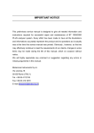
FIG. 3 is a diagram depicting a con?guration of a battery
testing device;
determines Whether the temperature of the secondary battery
FIG. 4 is a graph describing the change of each index in a
rises to 160° C. or more While holding the temperature of the
battery performance test;
secondary battery at 1500 C. for three hours, and displays the
result of this determination on a external device. Thereby for
performing the charge and recharge of the secondary battery
conforming to the actual Way of use of a portable telephone,
can be provided.
the secondary battery, by a repeat of the discharge and charge
of the secondary battery. Thereby the temperature of the
secondary battery is held at 1500 C. for three hours When the
battery capacity reaches 75%, 50% or 25% of the battery
capacity of the unused secondary battery by a repeat of the
discharge and charge of the secondary battery. Hence the state
mance of the secondary battery in the portable telephone
being connected for charging can be correctly evaluated.
According to the present invention, a battery testing device
and battery testing method Which alloWs accurately evaluat
ing the performance of a secondary battery in a portable
telephone being connected for charging, by applying a load of
50
FIG. 5 is a circuit diagram depicting a concrete circuit
the secondary battery Which rises to 1600 C. or higher tem
con?guration to implement a con?guration of a battery test
perature state because of the sudden start of a thermo-run
ing device;
aWay due to the start of thermal decomposition of the battery
materials at around 1500 C., it canbe decided Whether thermal
decomposition started, and the determination result can be
FIG. 6 is a graph depicting the changes of each index
according to a concrete circuit con?guration to implement the
55
displayed, Whereby Whether the secondary battery has risen
to 1600 C. or more can be evaluated.
performed;
To achieve the above object, a battery testing method
according to the present invention is a battery testing method
Which can charge a chargeable secondary battery by using
charging means for charging the secondary battery, the
method having: an input control step of controlling the input
poWer Which the charging means inputs to the secondary
battery, and an output control step of controlling the output
poWer Which is output from the secondary battery and dis
charging the secondary battery, Wherein When the secondary
battery reaches a fully charged state, the discharge of the
con?guration of a battery testing device;
FIG. 7 is a graph depicting the degree of the drop of battery
capacity When the cycle test to repeat charge and discharge is
60
FIG. 8 is a graph depicting the relationship betWeen the
battery voltage Vb and the charge ratio Qb of a lithium ion
battery;
65
FIG. 9 is a graph depicting the change of degree of the drop
of battery capacity based on the temperature change When the
cycle test to repeat charge and discharge is performed;
FIG. 10 is a graph depicting the temperature change of the
lithium ion battery based on the change of test time When the
cycle test to repeat charge and discharge is performed;
US 8,228,039 B2
6
5
FIG. 11 is a graph depicting the change of battery capacity
control circuit 3 sends a discharge start signal Sdis to the radio
circuit 4, and the radio circuit 4 Which received this signal
starts discharging the DC poWer P3 of the lithium ion battery
of the lithium ion battery based on the change of test time
When the cycle test to repeat charge and discharge is per
formed; and
FIG. 12 is a graph depicting the temperature change of the
2 (output control step).
lithium ion battery based on the change of test time When the
predetermined voltage (above mentioned recharge start volt
cycle test to repeat charge and discharge is performed.
age Vstart) state, the charge control circuit 3 sends a charge
stop signal Sdissstop to the radio circuit 4, and the radio
circuit 4 Which received this signal stops the discharge of the
lithium ion battery 2, While the charge control circuit 3 starts
charging the lithium ion battery 2 using the AC adapter 1.
Then the voltage Vb of the lithium ion battery 2 reaches a
DESCRIPTION OF THE PREFERRED
EMBODIMENTS
Here a predetermined voltage (recharge start voltage Vstart)
Preferred embodiments of the present invention Will noW
be described With reference to the accompanying draWings.
In the description of the draWings, the same composing ele
state is a state Where the need to start charging the lithium ion
battery 2 is generated.
In this Way, one discharge of the lithium ion battery 2 by the
radio circuit 4 and one charge of the lithium ion battery 2
using the AC adapter 1 by the charge control circuit 3 are
regarded as one cycle, and this cycle is repeated.
NoW the change of each index, such as poWers P1 to P3,
ments are denoted With the same symbols, for Which redun
dant description is omitted.
First a con?guration of a battery testing device 100 accord
ing to the present embodiment Will be described With refer
ence to FIG. 3. FIG. 3 is a diagram depicting the con?guration
of the battery testing device 100. The battery testing device
20
100 is a device for enabling the accurate testing of the per
formance of a lithium ion battery 2 (secondary battery) being
connected for charging by performing the charge using an AC
adapter 1 (charging module) for charging the lithium ion
battery 2 and the discharge of the lithium ion battery 2 to
apply load. The AC adapter 1 is connected to the portable
be described With reference to FIG. 4. FIG. 4 is a graph
depicting the change of each index (operation Waveform),
25
telephone 10 on the one hand, and is connected to a commer
cial poWer supply 9 on the other hand. The battery testing
device 100 has a charge control circuit 3 (input control mod
ule), a radio circuit 4 (output control module) and a tempera
battery voltage Vb (V) of the lithium ion battery 2 and charge
ratio (that is, the charged state) Qb (%), shoWn in FIG. 3, Will
Where the abscissa indicates the operation time, and the ordi
nate indicates the magnitude of each index. The battery volt
age Vstart in FIG. 4 is a voltage With Which the recharge of the
lithium ion battery 2 is started, the battery voltage Vstop is a
maximum voltage When the lithium ion battery 2 reaches the
fully charged state, and poWer Pstop is the charge stop poWer
30
to be a timing of the termination of charging the lithium ion
ture adjustment device 5 (temperature adjustment module).
The lithium ion battery 2 is a chargeable secondary battery.
battery 2.
First the lithium ion battery 2 is discharged immediately
Instead of the lithium ion battery 2, a lithium polymer battery
may be used as a chargeable secondary battery.
The charge control circuit 3 is a circuit to control the DC
poWer P2 (input poWer) Which is input to the lithium ion
battery 2 from the commercial poWer supply 9 via the AC
after the lithium ion battery 2 reaches the fully charged state
(timing Ta) to be a charge state Which is 95% of the battery
35
ing Ta to Tb), 5% of the battery capacity has been discharged
(Qb:95%) from the fully charged state (Qb:l00%). Dis
adapter 1. The control system for DC poWer P2 by the charge
control circuit 3 Will be described in detail later. The charge
control circuit 3 inputs DC poWer P2 out of the DC poWer P1,
Which is output from the AC adapter 1, to the lithium ion
charging the fully charged state by 5% is de?ned as DOD 5%
40
The radio circuit 4 is a circuit that functions as a load
45
(tWo-step charging by constant current CC+constant voltage
CV) is about 4.2 V, the charge termination poWer Pstop at the
end of the constant voltage CV period is about 0.21 W (:4.2
tuation (that is, a circuit having resistance load) may be used.
50
forming temperature adjustment (including the cooling func
temperature) of the lithium ion battery 2 at a predetermined
arbitrary temperature. The temperature adjustment device 5
lithium ion battery 2. The temperature display device 7 is a
device for displaying the temperature of the lithium ion bat
tery 2, measured by the thermister 6.
NoW poWer control methods by the charge control circuit 3
and the radio circuit 4 Will be described respectively With
reference to FIG. 3. While DC poWer P2 is being input from
the charge control circuit 3 to the lithium ion battery 2
55
charged state, the charge control circuit 3 stops charging the
lithium ion battery 2 using the AC adapter 1, While the charge
the recharge control circuit 3 controls the DC poWer P2,
Which is input to the lithium ion battery 2 via the AC adapter
1, and starts charging the lithium ion battery 2. Since the
voltage of the lithium ion battery 2 increases from about 4.0V
to 4.2 V in the constant current CC period, the DC poWer P2
value, Which is input to the lithium ion battery 2, also
60
increases.
When the voltage of the lithium ion battery 2 is increased to
about 4.2 V, [the constant current CC period] shifts to the
constant voltage CV period, and the charge control to input
inserted in the battery testing device 100 for charging (input
control step), When the lithium ion battery 2 reaches a fully
V><50 mA, Where 50 mA is a termination current of a general
battery in the constant voltage CV period).
When the voltage of the lithium ionbattery 2 drops to about
4.0 V, Which is the recharge start voltage Vstart (timing Tb),
tion and heating function) to hold the temperature (operation
has a thermister 6 and a temperature display device 7. The
thermister 6 is a device for measuring the temperature of the
voltage When the battery reaches fully charged state) accord
ing to the charging method for the lithium ion battery 2
circuit 4 Will be described in details later. Instead of the radio
circuit 4, a circuit to implement the adjustment of load ?uc
The temperature adjustment device 5 is a device for per
(DOD: Depth Of Discharge).
Concerning the charging/ discharging conditions of the
lithium ion battery 2, the recharge start voltage Vstart is about
4.0 V (corresponds to 95% battery capacity), the maximum
voltage Vstop in the constant current CC period (maximum
battery 2.
device, Which controls the output poWer P3 being output from
the lithium ion battery 2, and discharges the lithium ion bat
tery 2. The control system for the output poWer P3 by the radio
capacity in the fully charged state (that is, the charge capacity)
(timing Tb). In other Words, after this discharge period (tim
65
DC poWer P2 to the lithium ion battery 2 is performed While
constantly maintaining the voltage to about 4 .2 V. At this time,
the DC poWer P2 decreases at a predetermined gradient, and
the charge control stops When the DC poWer P2 reaches the
US 8,228,039 B2
7
8
charge termination power Pstop (:0.21 W) (timing Tc). Here
(V) and the charge ratio (that is the charged state) Qb (%) of
the charge control circuit 3 sends the discharge start signal
Sdis to the radio circuit 4 (that is, turns ON dis), and the radio
circuit 4 Which received this signal starts discharge of the
poWer P3 of the lithium ion battery 2. In this discharge period
(timings Tc to Td), the battery Vb of the lithium ion battery 2
decreases from about 4.2V, and When the voltageVb becomes
about 4.0 V, Which is the recharge start voltage Vstart (timing
Td), the recharge control circuit 3 sends the discharge stop
signal Sdisstop to the radio circuit 4 (that is, turns OFF Sdis),
and the radio circuit 4 Which received this signal stops the
discharge of the lithium ion battery 2, While the charge control
circuit 3 starts the charge of the lithium ion battery 2 using the
AC adapter 1.
In this Way, one discharge of the lithium ion battery 2 by the
radio circuit 4 and one charge of the lithium ion battery 2 by
the charge control circuit 3 using the AC adapter 1 are
regarded as one cycle, and this cycle is repeated.
the lithium ion battery 2, Where the abscissa indicates the
operation time, and the ordinate indicates the battery voltage
Vb and the charge ratio Qb. As FIG. 8 shoWs, When a voltage
Vb (eg about 4.0 V) corresponding to the 95% Oh charge
ratio (that is, a 5% DOD) is determined, this voltage Vb
becomes the recharge start voltage Vstart.
NoW the change of degree of the drop of battery capacity
(that is, the capacity deterioration of the battery) due to the
temperature change, When the cycle test to repeat charge and
discharge of the lithium ion battery 2, Will be described With
reference to FIG. 9. FIG. 9 is a graph depicting the change of
degree of drop of battery capacity due to temperature change,
When the cyclic test to repeat charge and recharge is per
formed for one year, Where the abscissa indicates the tem
perature of the lithium ion battery 2, and the ordinate indi
cates the deterioration degree (%). Here 5% DOD is a test
condition, and testing is performed holding the temperature to
NoW a concrete circuit con?guration to implement the
con?guration of the battery testing device 100, shoWn in FIG.
about 20° C., to about 30° C., to about 40° C. and to about 50°
20
C. respectively. As FIG. 9 shoWs, When the temperature is
3, Will be described With reference to FIG. 5. FIG. 5 is a circuit
increased to about 20° C., to about 30° C. and to about 40° C.
diagram for depicting the concrete circuit con?guration to
implement the con?guration of the battery testing device 1 00.
In order to implement the con?guration of the battery testing
progresses little, but in the case of about 50° C., the capacity
deterioration of the battery suddenly progresses. Hence the
device 100, the sWitches 21 and 24, FET 22 (Field-Effect
Transistor) and the current detection resistor 23 are disposed.
NoW the change of each index, such as the currents I1 to I3
(A), the voltages V1, V211 and V2!) (V), the battery voltage Vb
(V) of the lithium ion battery 2, and the charge ratio (that is,
the charged state) Qb (%) shoWn in FIG. 5 Will be described
respectively, the capacity deterioration of the battery
25
capacity deterioration of the battery can rapidly progress by
testing the lithium ion battery 2 With holding the temperature
to about 50° C.
NoW the temperature change of the lithium ion battery 2
due to the change of test time When the cycle test to repeat
30
charge and discharge of the lithium ion battery 2 is performed
With reference to FIG. 6. FIG. 6 is a graph for describing the
Will be described With reference to FIG. 10. FIG. 10 is a graph
change of each index (operation Waveform), Where the
depicting the temperature change of the lithium ion battery 2
abscissa indicates the operation time, and the ordinate indi
cates the magnitude of each index. Here the battery voltage
charge and discharge is performed, Where the abscissa indi
Vstart in FIG. 6 is a voltage at Which the recharge of the
due to the change of test time When the cycle test to repeat
35
cate the test time, and the ordinate indicates the setting tem
40
perature by the temperature adjustment device 5. In this case,
When the battery capacity of the lithium ion battery 2 dete
riorates to a predetermined ratio (eg 75%) of the battery
capacity of the lithium ion battery 2 that is not in use (100%),
the temperature adjustment device 5 increases the tempera
lithium ion battery 2 is started, and the battery voltage Vstop
is the maximum voltage at Which the lithium ion battery 2
reaches the fully charged state.
NoW the degree of drop of the battery capacity (that is, the
capacity deterioration of the battery) When a cycle test to
repeat the charge and discharge of the lithium ion battery 2
ture of the lithium ion battery 2 from about 50° C., Which is a
normal test temperature, to about 150° C., and then holds
[temperature at about 150° C.] for three hours. Here the case
Will be described With reference to FIG. 7. FIG. 7 is a graph
depicting the degree of the drop of battery capacity When a
cycle test, to repeat charge and discharge, is performed for a
year, Where the abscissa indicates the depth of discharge
(DOD), and the ordinate indicates the deterioration degree
(%). Here the temperature of the lithium ion battery 2 is held
to about 50° C. using the temperature adjustment device 5,
45
described With reference to FIG. 11. FIG. 11 is a graph depict
and this temperature is regarded as a test temperature.
FIG. 7 shoWs the degree of drop of the battery capacity in
the cycle test When the depth of discharge (DOD) is constant.
For the depth of discharge, values in several steps, from 5% to
100%, are provided, and testing is performed using each of
these values. As FIG. 7 shoWs, the degree of capacity dete
rioration (that is, the deterioration amount) of the lithium ion
battery 2 increases as the depth of discharge (that is, the
discharge amount) decreases (that is, as the value becomes
50
due to the change of test time When the cycle test to repeat
cates the test time, and the ordinate indicates the setting
temperature by the temperature adjustment device 5. Here 5%
55
closer to 5%). Therefore a lithium ion battery 2, When the
is not used (neW product and same type), the temperature
adjustment device 5 makes an adjustment so that the tempera
ture of the lithium ion battery 2 is held at about 150° C. for
three hours.
As FIG. 11 shoWs, if about half a year has elapsed from the
value, With Which the capacity deterioration degree becomes
the Worst.
state) Qb (%) Will be described With reference to FIG. 8. FIG.
8 is a graph depicting a relationship of the battery voltage Vb
DOD is the test condition, and the test is performed With
holding the temperature at about 50° C. After the battery
capacity of the lithium ion battery 2 reaches 75%, 50% or
25% of the battery capacity of the lithium ion battery Which is
the same type and same model of this lithium ion battery 2 and
60
state), can be de?ned as a lithium ion battery 2 having a Worst
NoW the relationship of the battery voltage Vb (V) of the
lithium ion battery 2 and the charge ratio (that is, the charged
ing a change of battery capacity of the lithium ion battery 2
charge and discharge is performed, Where the abscissa indi
cycle test is performed With the depth of discharge as 5% (that
is, discharge up to 95% of the battery capacity fully charged
When the temperature of the lithium ion battery 2 spontane
ously changes Will be described later.
NoW the change of battery capacity of the lithium ion
battery 2 due to the change of test time When the cycle test to
repeat charge and discharge of the lithium ion battery 2 Will be
65
unused battery state (100% battery capacity), then the battery
capacity deteriorates to 75% of the battery capacity in the
fully charged state, then if about one year has elapsed from the
US 8,228,039 B2
10
unused battery state, the battery capacity deteriorates to 50%
of the battery capacity in the fully charged state, and if about
tWo years have elapsed from the unused battery state, the
battery capacity deteriorates to 25% of the battery capacity in
the fully charged state. This means that the degree of capacity
deterioration of the battery can be adjusted by adjusting the
While the radio circuit 4 starts discharging the lithium ion
battery 2, and When the lithium ion battery 2 reaches a pre
determined charged state, the radio circuit 4 stops discharging
the lithium battery 2, While the charge control circuit 3 starts
charging the lithium ion battery 2 using the AC adapter 1.
Thereby When the lithium ion battery 2 reaches the fully
charged state, a discharge of the lithium ion battery 2 starts,
and When the lithium ion battery 2 reaches a predetermined
charged state, charge of the lithium ion battery 2 starts, and
this cycle is repeated. Therefore the performance of the
lithium ion battery 2 in a portable telephone 10 being con
nected for charging can be more accurately evaluated by
applying a load of charging and discharging the lithium ion
battery 2 conforming to the actual Way of use, such as using
test time.
NoW the temperature change of the lithium ion battery 2
due to the change of test time When the cycle test to repeat
charge and discharge of the lithium ion battery 2 Will be
described With reference to FIG. 12. FIG. 12 is a graph depict
ing a temperature change of the lithium ion battery 2 due to
the change of test time When the cycle test to repeat charge
and discharge is performed, Where the abscissa indicates the
test time, and the ordinate indicates the setting temperature by
the temperature adjustment device 5 and the battery voltage.
Here When the battery capacity of the lithium ion battery 2
the portable phone 10 While being charged via the AC adapter
1, for example. Thereby a test to evaluate performance using
deteriorate to 75%, 50% or 25% of the charged state of the
the lithium ion battery 2 in this state becomes possible. Also
input poWer control and output poWer control for the lithium
ion battery 2 at a temperature adjusted by the temperature
adjustment device 5 are performed. Hence the in?uence of
temperature on the performance of the lithium ion battery 2
battery capacity in an unused state (100%), the temperature
adjustment device 5 increases the temperature of the lithium
ion battery 2 from about 50° C., Which is the normal test
temperature, to about 150° C., and then holds [the tempera
20
can be accurately evaluated. Thereby a test to evaluate per
formance using the lithium ion battery 2 in this state can be
ture at about 150° C.] for three hours.
While holding the temperature of the lithium ion battery 2
at about 150° C. for three hours, the temperature adjustment
device 5 judges Whether the temperature of the lithium ion
25
In the actual operation of the portable telephone 10, the
charge period and discharge period overlap, but in the present
embodiment, the charge period and discharge period are
battery 2 increases to about 160° C. or more using the ther
mister 6. The temperature adjustment device 5 distinguishes
separated and modeled to be equivalent, as mentioned above.
a lithium ion battery 2 of Which temperature is increased to
about 160° C. or more as an NG battery Which is not appro
30
priate to be used for a portable telephone 10, and displays this
information on the temperature display device 7, and distin
guishes a lithium ion battery 2 of Which temperature does not
increase to about 160° C. or more (that is, increases to a
temperature less than about 160° C.) as an OK battery Which
What is claimed is:
1. A battery testing device that charges a chargeable sec
ondary battery by using a charging module, comprising:
Thereby a non-defective battery (OK battery) of Which
an input control module that controls an input poWer that
temperature does not increases to about 160° C. or more even
40
the charging module inputs to the secondary battery;
an output control module that controls an output poWer that
is output from the secondary battery and discharges the
secondary battery;
a temperature adjustment device con?gured to heat and
45
cool the secondary battery, the temperature adjustment
device con?gured to increase the temperature of the
secondary battery from a ?rst temperature of about 50°
ity in an unused state, heating is started When the battery
capacity becomes a predetermined value.
Concerning the thermal stability of the lithium ion battery
2, a current lithium ion battery sometimes becomes about a
160° C. orhigher temperature state When heated to about 150°
In other Words, in the lithium ion battery 2, the charge mode
and discharge mode are separated, and [the lithium ion bat
tery 2] is operated only in one of these modes at a time, so the
operation pattern is speci?ed such that the charge mode and
discharge mode are separated.
35
is appropriate to be used for a portable telephone 10, and
displays this information on the temperature display device 7.
if [the battery] heats up to about 150° C. can be selected from
the lithium ion batteries 2 of Which capacity deteriorated to
75%, 50% or 25% of the battery capacity in an unused state.
In the case of a lithium ion battery 2 having a battery capacity
in an unused state (100%), heating to about 150° C. is per
formed immediately, and in the case of a lithium ion battery 2
of Which battery capacity is 75% or less of the battery capac
performed.
C. to a second temperature of about 150° C. for a period
50
of about 3 hours When a battery capacity of the second
ary battery falls beloW a threshold,
Wherein the temperature adjustment device judges Whether
C., since the thermal decomposition of the battery materials
starts and thermo-runaWay suddenly begins. Therefore it is a
the temperature of the secondary battery rises to 160° C.
critical safety con?rmation for a lithium ion battery 2 to check
perature of the secondary battery at the second tempera
that this thermal decomposition and thermo-runaWay is not
generated even if [the battery] heats up to about 150° C. (that
is, a temperature threshold, at Which thermal decomposition
and thermo-runaWay occurs, does not drop). A case of the
lithium ion battery 2 becoming about 150° C. is a case of
internal failure, such as a short, occurring to the lithium ion
battery 2 or a case of the lithium ion battery 2 externally being
heated (dropping into hot tempura oil or being left in a car on
or more While performing adjustment to hold the tem
55
device,
Wherein the input control module and the output control
module are con?gured to cyclically perform a plurality
60
of charge/discharge cycles, and
each charge/ discharge cycle includes:
When the secondary battery reaches a fully charged state,
the output control module starts discharging the sec
ondary battery While the input control module stops
a hot summer day).
As described above, according to the battery testing device
100 of the present invention, if the lithium ion battery 2
reaches a fully charged state, the charge control circuit 3 stops
charging the lithium ion battery 2 using the AC adapter 1,
ture, and displays a result of the judgment on an external
charging the secondary battery using the charging
65
module, and
When the secondary battery reaches a predetermined
charged state, the input control module starts charging
US 8,228,039 B2
11
12
the secondary battery, by the cyclically performed plurality of
charge/discharge cycles of the secondary battery.
the secondary battery using the charging module
While the output control module stops discharging the
secondary battery.
2. The battery testing device according to claim 1, Wherein
the output control module discharges the secondary battery
6. A battery testing method that charges a chargeable sec
ondary battery by using a charging module, comprising:
5
until reaching a state of 95% of the battery capacity in the
controlling an output poWer that is output from the second
fully charged state When the secondary battery reaches the
fully charged state.
3. The battery testing device according to claim 1, Wherein
the input control module controls the input poWer that is input
to the secondary battery at the temperature adjusted by the
ary battery and discharges the secondary battery; and
increasing a temperature of the secondary battery from a
?rst temperature of about 50° C. to a second temperature
of about 150° C. for a period of about 3 hours When a
battery capacity of the secondary battery falls beloW a
temperature adjustment device, using the charging module,
threshold,
and
judging Whether the temperature of the secondary battery
the output control module discharges the secondary battery
by controlling the output poWer that is output from the
secondary battery at the temperature adjusted by the
temperature adjustment device.
4. The battery testing device according to claim 3, Wherein:
the input control module controls the input poWer, Which is
input in use of the charging module, to the secondary
battery held at the ?rst temperature as adjusted by the
temperature adjustment device, and
the output control module discharges the secondary battery
by controlling the output poWer that is output from the
rises to 160° C. or more While performing adjustment to
hold the temperature of the secondary battery at the
second temperature, and displaying a result of the judg
ment on an external device,
20
When the secondary battery reaches a fully charged state,
discharging the secondary battery is started in the
25
controlling an output poWer, and the controlling an
input poWer is stopped, and
When the secondary battery reaches a predetermined
adjusted by the temperature adjustment device.
capacity of an unused secondary battery of the same type as
Wherein the controlling an input poWer and controlling an
output poWer are cyclically performed in a plurality of
charge/discharge cycles, and
each charge/ discharge cycle includes:
secondary battery held at the ?rst temperature as
5. The battery testing device according to claim 4, Wherein
the temperature adjustment device makes the adjustment to
hold the temperature of the secondary battery at the second
temperature for three hours When the battery capacity of the
secondary battery reaches 75%, 50% or 25% of a battery
controlling an input poWer that the charging module inputs
to the secondary battery; and
charged state, charging the secondary battery using
30
the charging module is started in the controlling an
input poWer, and the controlling an output poWer is
stopped.