1
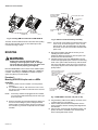
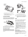
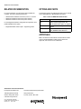
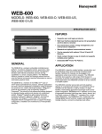
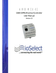
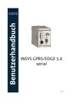
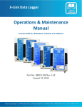
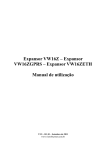
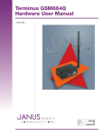
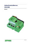
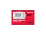
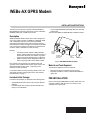
WEBs-AX GPRS Modem
INSTALLATION INSTRUCTIONS
This document covers the mounting of the NPB-GPRS-H/
NPB-GPRS-W-H wireless modem option card in a WEB-201,
WEB-600, WEB-700, or WEB-870 controller.
• A right-angle GSM/GPRS quad-band SMA coax-mounted
stub antenna.
This document WEBs-AX GPRS Modem Installation Sheets.
Description
WEBs-AX GPRS cellular modem option card is designed to
mount in an option card slot of a WEB-201, WEB-600, WEB700, or WEB-870 controller. This modem uses GPRS
(General Packet Radio Service) data technology and has 2
LED indicators for status and signal. An antenna with an SMA
coax connector is included in the package. An optional coax
extension cable is available for remote mounting.
NOTES:
—
—
The GPRS modem requires a SIM (subscriber
identity module) card from an approved vendor. At
the time this document was created, only a SIM
card provisioned by Wyless Group is supported.
WEBs controllers require NiagaraAX build 3.4 or
later to support operation of the GPRS modem.
Stat
u
Sign s
al
Ant
enn
a
LEDS (2)
STATUS
SIGNAL
ANTENNA
CONNECTOR
SMA COAX
SUPPLIED
STUB
ANTENNA
M29144
Fig. 1. NPB-GPRS-H Modem Option.
Not covered in this document is the software setup and
operation of the installed GPRS modem option. Refer to the
NiagaraAX GPRS modem option - engineering notes
document for this information.
Material and Tools Required
For all other related mounting and wiring details, refer to the
appropriate mounting and wiring document. See “Related
Documentation” on page 4.
• SIM card from approved wireless service provider.
• #2 phillips screwdriver: used to install the NPB-GPRS-H
option card.
Included in this Package
PRE-INSTALLATION
Included in this package you should find the following items:
• An NPB-GPRS-H modem option card, with pre-attached
endplate.
• If an NPB-GPRS-W-H, a Wyless provisioned SIM card,
ready for “Pre-installation”.
The following supplies and tools are required:
Prior to mounting the NPB-GPRS-H modem option card in the
controller, install the SIM card into the connector on the
underside of the option card.
62-0301-01
WEBS-AX GPRS MODEM
SCREWS (4)
BATTERY ASSEMBLY
(INCLUDES CABLE
AND BRACKET)
UNPLUG BATTERY HERE
OPTION SLOT
2 AREA
SIM CARD
ANGLED
CORNER OUT
SIM CARD
SEATED FULLY
IN CONNECTOR
BLANKING END
PLATE
OPTION SLOT
1 AREA
M29145
Fig. 2. Inserting SIM into underside of NPB-GPRS-H.
201 OR 600
CONTROLLER
M27412
Fig. 3. Remove screws and battery assembly.
To install, orient the SIM with its foil connectors down (writing
side up) and its angled corner out, and slide fully into the
connector. See Fig. 2 above.
MOUNTING
NOTE: The tie wrap on the battery pack should have its lock
“knot” on top, as shown in Figure 3. If not, cut and
remove the tie, then re-install another tie wrap with
its lock tab on top. (Tie lock at bottom interferes with
option card).
4.
WARNING
5.
Power to the controller must be OFF when
installing or removing option cards, or damage
will occur! Be very careful to plug any option card
into its connector properly (pins aligned).
Mount the NPB-GPRS-H card in either of the available option
card slots of a WEB-201, WEB-600, WEB-700, or WEB-870
controller. If mounting on a WEB-870 controller, the upper
option slot (Slot 2) is recommended.
Remove the blanking end plate for the slot you are
installing the option card into.
(Retain the blanking end plate in case the option card
must be removed at a later date.)
Carefully insert the pins of the NPB-GPRS-H into the
socket of the appropriate option card slot. The mounting
holes on the option board should line up with the standoffs on the base board. If they do not, the connector is
not properly aligned. Press until the option card is completely seated.
INSERT NPB-GPRS-H CARD
INTO OPTION CARD SLOT
CAREFULLY, WITH
PINS ALIGNED. FULLY
SEAT CARD.
201 OR 600 CONTROLLER
BATTERY CONNECTOR
Procedure 1:
Mounting NPB-GPRS-H option card on a WEBs
controller.
1.
2.
Remove power from the controller—see the previous
Warning.
For a WEB-201, 600, or 700, remove the cover. To do
this, press in the four tabs on both ends of the unit, and
lift the cover off.
PLACE NPB-GPRS-H
CUSTOM PLATE
OVER END
M29146
NOTE: If accessory modules are plugged into the controller,
you may need to slide them away from the unit to get
to the cover tabs.
3.
Remove the battery and bracket assembly by taking out
the four screws holding it in place, setting the screws
aside for later. Unplug the battery from the connector on
the controller. Fig. 3 shows an exploded view of a WEB201/600.
62-0301—01
2
Fig. 4. NPB-GPRS-H inserted, end plate on top.
6.
7.
8.
Plug the battery cable into the battery connector on the
controller (see Fig. 4 for location).
Set the battery and bracket assembly back over the
option card slots, with the mounting holes aligned with
the standoffs.
Place the four screws through the battery bracket, end
plates, and into the standoffs on the controller base
board. Hand tighten these screws.
WEBS-AX GPRS MODEM
HAND TIGHTEN THE
FOUR SCREWS
THROUGH BATTERY
BRACKET, END
PLATES, INTO
STANDOFFS.
2
(51)
15/64 (6)
5/8
(16)
Ø
1-1/4 (32)
1-1/8
(30)
5/8
(16)
M29147
MOUNTING
HOLES (2)
Ø 1/64 (4)
Fig. 5. Re-fasten screws through battery bracket.
9.
Replace the controller cover.
If accessory modules were unplugged, plug them back
into the controller as before, and secure.
ATTACHING ANTENNA
A GSM/GPRS stub antenna with right-angle SMA male coax
connector is provided for use with WEB-201, WEB-600, WEB700 controller. To attach, simply insert into the SMA coax jack
on the modem, and finger-tighten the knurled nut (Fig. 3).
1 (25)
M29149
Fig. 7. H-GPRS-CBL-EXT bracket details.
Some installations may require a different external antenna.
NOTE: Any external antenna must be compatible with the
GSM 900/1800 frequency and the 50Ω impedance of
the SMA coax connector on the NPB-GPRS-H
modem.
LEDS
Two LEDs are located on the endplate of the NPB-GPRS-H
option card. On the option card label these appear as
“STATUS” and “SIGNAL”—see Fig. 1 on page 1.
These two LEDs are briefly described as follows:
SUB ANTENNA
INSTALLED ON
NPB-GPRS MODEM
OPTION CARD
M29148
Fig. 6. SMA stub antenna on WEB-201/600.
Rotate in whatever position is needed for mounting clearance
and/or best reception. If needed, you can use the H-GPRSCBL-EXT “Antenna Extension Option”.
Antenna Extension Option
To locate the included stub antenna remotely from controller,
order and install the H-GPRS-CBL-EXT option. Included is a
6.56 ft. (2m) SMA-type coax extension cable and steel bracket
for wall or panel mounting. See Fig. 7 for bracket details and
dimensions.
• STATUS (green) — Flashes various LED patterns based
on the state of the modem. This LED is directly under
control of the modem itself (rather than the NiagaraAX
modem driver).
Upon initial power up, the Status LED pattern is typically
600ms On / 600ms Off, and may change depending on
various modem state changes.
• SIGNAL (green) — Indicates the RSSI (received signal
strength indicator), according to the number of short
(350ms On) flash patterns. Analogous to “number of bars”
on a cell phone.
For further details on the operation of both LEDs, see the
NiagaraAX GPRS modem option - Engineering Notes
document.
Modem Checkout
After mounting the NPB-GPRS-H modem option and
attaching the antenna, power the controller on. Following
reboot of the controller, the modem is configured by opening a
platform connection to the controller.
To verify modem communications, verify that status properties
in the “GPRS Modem Configuration” platform view show
returned values.
3
62-0301—01
WEBS-AX GPRS MODEM
RELATED DOCUMENTATION
OPTIONS AND PARTS
For more information on mounting and wiring a WEBs-AX
controller, refer to the following documents:
The following options and replacement parts may be ordered
for the NPB-GPRS-H or NPB-GPRS-W-H modem:
• WEB-201/600 Installation Instructions, Form no. 95-7722
• WEB-700 Installation Instructions (future release)
• WEB-870 Installation Instructions (future release)
For the NiagaraAX software configuration and operation of the
installed GPRS modem option:
• NiagaraAX GPRS modem option - Engineering Notes
Table 1. Parts for WEBs-AX GPRS modem.
Option/Part
H-GPRS-CBLEXT
H-GPRS-SIM-W
NPB-GPRS-H
Description
6.56 ft (2m) SMA-type coax extension
cable, and mounting bracket. See
“Antenna Extension Option” on page 3.
Replacement SIM card, provisioned by
Wyless.
Replacement GPRS modem option
card, without bundled SIM card.
APPROVALS
FCC: The Siemens TC63 cellular communications module
used on the NPB-GPRS-H modem option card is FCC
approved, and has an FCC ID of QIPTC63.
Automation and Control Solutions
Honeywell International Inc.
Honeywell Limited-Honeywell Limitée
1985 Douglas Drive North
35 Dynamic Drive
Golden Valley, MN 55422
Toronto, Ontario M1V 4Z9
customer.honeywell.com
® U.S. Registered Trademark
© 2009 Honeywell International Inc.
62-0301—01 M.S. 02-09