1
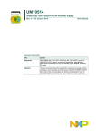
International Journal of Emerging Technology in Computer Science & Electronics (IJETCSE) ISSN: 0976-1353 Volume 13 Issue 2 –MARCH 2015. Energy Harvesting Wireless Sensor Node for detecting intervention in Unmanned places using Solar Cells Alagumeenal.N [1]Bala Sundari.S [2] Mrs.M.Meenalakshmi [3] [1], [2] B.E., Students, Electronics and Communication Engineering,Mepco Schlenk Engineering College, Sivakasi, India [3] M.E., Assistant Professor, Electronics and Communication Engineering,Mepco Schlenk Engineering College, Sivakasi, India Typically,awirelesssensornodeconsistsofcontroller, communicationdevice, powersupply, sensors and actuators.These components are integratedonasingleormultiple boards.AWSNusually consistso f suchnodesthatcommunicatethroughwireless channelsforinformationsharing andcooperative processing. WSNscanbe deployedonaglobalscaleformonitoringandhabitat study, ina battlefieldformilitary surveillance, forsearch and rescue, infactories forcondition b a s e d maintenance,health monitoring,eveninbodiesforpatientmonitoring. Abstract:Wireless Sensor Nodes (WSN)are usually thrown at places to detect some changes in physical or environmental parameters. Conventional wireless sensor nodes are powered by batteries. Since batteries are exhaustible, the lifetime of sensor node is limited. So it is good to use solar panel and rechargeable battery combination to power up the node. During day time, energy produced by solar panel will power the Arduino and charge the battery as well.During night,charged battery will be used for operation of node.This energy is used to detect intervention in unmanned places using PIR sensor.The distance at which the detected object or human is present is measured using Ultrasonic sensor.Then detected data is sent to the respective person through GSM.Thus some preventive measures can be taken. It is applicable for monitoring border areas,nuclear power plants, etc.. These nodes are energy efficient and cost efficient compared to the conventional nodes which uses batteries. Index terms: Energyharvesting, Wireless sensor node, motion detection I. Introduction Withthepopularityof intelligentelectronics inthe post-PCera, computing d e v i c e s havebecome moremobile, moredistributed,and indaily life. Itisnowpossibletoconstruct, a walletsizeembedded systemwiththeequivalentcapabilityof90’sPC.Fro m thisperspective, t h e emergenceof wirelesssensornetworks (WSNs) isessentially the latesttrend o f miniaturizationandubiquityofcomputing devices. Fig1: Block diagram of wireless sensor node In 103 a typicalscenario, users canobtaini n f o r m a t i o n ofinterest fromaWSNbymaking q ueries and gatheringresults fr o mthebase stations orsinknodes,whichactsasaninterfacebetweenusersandthe network. Inthisway,WSNscanbeconsideredasadistributeddatabas e. TheeraofWSNsishighlyexpectedinthenearfuture. International Journal of Emerging Technology in Computer Science & Electronics (IJETCSE) ISSN: 0976-1353 Volume 13 Issue 2 –MARCH 2015. II.Project Description object.Then the information about the distance of the intervened object is sent to arduino.Arduino sends the detected information to control room or respective authorities through GSM. One of the main challenges of WSN is energy source provided for the node.If batteryis used to power up node is dead,then entire node becomes useless and other node should be switched ON to do former node’s duty. Usage of renewable energy source to replace batteries would be better choice to increase lifetime of nodeand to avoid wastage of resources like microcontroller, transceiver, and sensors in node if battery is dead. III.Hardware Description and Implementation A.Solar panel based Voltage source: Fig2:Block diagram of energy harvesting node 3V Solar panel is sufficient for powering up the arduino and sensors used in wireless sensor node [1]. Energy produced from the solar panel is given as input to the buck converter.Then the input voltage (3V) is converted to constant 9V.Output from buck converter is used to power arduino and used to charge the rechargeable battery as well [2]. During day time, arduino gets power directly through buck converter.In night time, rechargeable batteries which are charged by solar panel are used to power the arduino.The operation is similar to an offline UPS. Fig3: Energy harvesting setup Here, there is a constant 3.3V supply from panel from 9.00 a.m to 6.00p.m.When the panel produces Vout>2.9V, then buck converter is capable of producing output of 27V or more. In this instance, it is tuned in such a way to produce 9v output. Output from buck booster is passed through IC7805 to produce constant 5V.Both Leds are used only for indicating from where voltage is being generated. Both Capacitors are just filters used to remove spikes. Then Diode is used as a freewheeling diode since voltage is DC and load is inductive (since relay is a coil).Battery is connected to normal close pin of relay. Buck booster will power arduino and charge battery at the same time. Until buck booster provides power, relay will be connected to normal open. During night, when there is no output from buck booster,Battery starts discharging since relay will be normally closed. Thus there will be a constant 5V Output from circuit. When there is any intervention in the area where the sensor nodes are thrown,the PIR sensor measures IR light radiating from objects in its field of view [8] .Motion is detected when an infrared source with one temperature, such as a human being, passes in front of an infrared source with another temperature, such as a wall.When the motion is detected it sends the control signal to the arduino. Then the arduino sends signal to HCSRO4 ultrasonic sensor to measure the distance of the intervening object which is detected by pir sensor.The HC-SR04 Ultrasonic sensoruses sonar to detect the distance of the 104 International Journal of Emerging Technology in Computer Science & Electronics (IJETCSE) ISSN: 0976-1353 Volume 13 Issue 2 –MARCH 2015. B.Arduino: The Arduino Uno is a microcontroller board based on the ATmega328. It has 14 digital input/output pins (of which 6 can be used as PWM outputs), six analog inputs,16 MHz ceramic resonator, a power jack,USB connection, an ICSP header, and a reset button. It has everything needed to support the microcontroller; simply connect it to a computer with a USB cable or power it with a AC-to-DC adapter or battery to get started. An easy USB interface. Very convenient power management and built-in voltage regulation. An easy-to-find and cheap microcontroller. A 16 MHz clock. This makes it fast enough for many applications. 32 KB of flash memory for storing the code. 13 digital pins and 6 analog pins. An ICSP connector for bypassing the USB port and interfacing the Arduino directly as a serial device. An on-board LED attached to digital pin 13 for fast and easy debugging of code. C.PIR sensor: The Arduino Uno can be powered via the USB connection or with an external power supply. The power source is automatically selected. The board can work on an external supply of 6 to 20 volts. If supplied with lesser voltage than 7V, the 5V pin may supply less than five volts and the board may be unstable. If using more voltage than 12V, the voltage regulator may overheat and damage the board. The recommended voltage range is 7 to 12 volts. The ATmega328 has2 KB of SRAM and 1 KB of EEPROM. A Passive Infra-Red sensor (PIR sensor) is an electronic device which measures IR light emitting from objects in its overall field of view. Motion is detected when IR source with one temperature, such as human beings, travels in front of another infrared source like wall. This energy is not visible to the naked human eye but can be observed by electronic devices designed for such a purpose. The term 'passive' here means the PIR will not emit energy of any type but accepts incoming infrared radiation only. The Arduino Uno can be programmed with the Arduino software. Select "Arduino Uno from the Tools > Board menu (according to the microcontroller on board) [7] Fig5:PIR sensor Fig4: Arduino Board Features of PIR sensor are: Some of the important features of the Arduino Uno include: An open source design. The advantage of it being open source is that it has a large communityof people using and troubleshooting it. 105 High sensitivity. Compact size (24 x 32 mm). Delay time:5secs - 18 minutes Supply voltage: DC 4.5V - 5V. Light sensor: CdS Type photocell Voltage Output: International Journal of Emerging Technology in Computer Science & Electronics (IJETCSE) ISSN: 0976-1353 Volume 13 Issue 2 –MARCH 2015. 1) High level signal :3V. 2) Low level signal :0V. TTL output. Current drain :< 50uA. Range : 3m. Infrared sensor: low noise, dual element Power up behavior: Most of the PIR modules require time in settling down. As soon as the module is powered up, it will radiate a 500ms HIGH pulse, followed by another 300-400ms HIGH pulse at about 7-15 seconds. Fig7:BISS0001 PIR module detection pulses D.Ultrasonic Sensor: The HC-SR04 ultrasonic sensor uses sonar to find distance to an object. It provides excellent noncontact range detection with high accuracy and stable readings from 2cm to 400 cm or 1” to 13 feet. It operation is not at all affected by sunlight or black material. Features of Ultrasonic sensor are: As the capacitors start charging up, a subsequent power up of the module will result in a shorter time between these two pulses. After those two pulses, the module will stabilize itself. The stabilization process will be within 60 - 120 seconds .Until module gets stabilized the module will randomly pulse HIGH and LOW [7]. Power Supply :+5V DC Dimension: 45mm x 20mm x 15mm Quiescent Current:<2mA Working Current:15mA Resolution : 0.3 cm Effectual Angle: <15° Ranging Distance: 2cm– 400 cm/1" - 13ft Measuring Angle: 30 degree Trigger Input Pulse width: 10uS Fig6:BISS0001 PIR module power up pulses Behavior after stabilized: After the module is stabilized, when no object passes by,then the Vo PINwill stay LOW at about 0.4VDC, but Arduino has no problem picking it as a logic LOW. When an object with IR radiation passes, the module starts emitting 3-5 high pulses depending on how long the object stays in range. The high pulse width will be varying between 200ms to 600ms [7]. Fig8:SR04 Ultrasonic sensor 106 International Journal of Emerging Technology in Computer Science & Electronics (IJETCSE) ISSN: 0976-1353 Volume 13 Issue 2 –MARCH 2015. Fig10:SIM300 GSM Module SIM300isaTribandGSM/GPRSenginethatworksonfrequenciesEGSM9 00MHz,DCS1800MHzandPCS1900MHz.SIM300provi desGPRS multi-slotclass10capability. With atiny configuration of40mmx33mmx2.85mm,SIM300canfitalmostallthespa ce requirementinany application,suchasSmartphone,PDA phoneand othermobile device.SIM300provideRFantenna interface with twoalternatives:antennaconnectorandantennapad. Fig9: Working of ultrasonic sensor To measure distance, Trig pin ofSR04 must receive a HIGH pulse (5V) for at least 10us, this will initiate the sensor to transmit out 8 cycle of ultrasonic burst at 40 kHzand wait for the reflected ultrasonic burst. When the sensor detected ultrasonic burst from receiver, it will set the Echo pin to high (5V) and time taken from sending signal to receiving signal at Echo is proportional to distance. Here time is equal to width of echo pulse in us [5]. The SIM300is designedwithpower savingtechnique, the currentconsumptiontoaslow as2.5mA inSLEEPmode. TheSIM300is integratedwith theTCP/IP protocol. ExtendedTCP/IPATcommands are alsodevelopedforcustomerstousetheTCP/IPprotocol whichisvery usefulfordata transfer applications [9]. Distance in cm = Time / 58 E.GSM GSM (Global System for Mobile Communications), is a standard which is developed by the European Telecommunications Standards Institute (ETSI) to describe protocols for second-generation (2G) digital cellular networks used by mobile phones. "GSM" is a trademark owned by the GSM Association. IV.Applications and Advantages 2G networks developed as a replacement for first generation (1G) analog cellular networks, and the GSM standard originally defined a digital, circuit-switched network optimized for full duplex voice telephony. This is improved over time to include data communications, first by circuit-switched transport, and then by packet data transport via GPRS (General Packet Radio Services) and EDGE (Enhanced Data rates for GSM Evolution or EGPRS)[4]. Can be used wherever the node should be working all the time. Can be deployed at border security areas, military areas, bank lockers, nuclear reactors and places where any intervention (human or animal) is strictly prohibited. Can be taken into consideration whenever both more energy at less cost is the major parameter concerned. V.Results In Solar panel based voltage source, buck booster produces 9V output when panel receives sunlight. As in Fig11, battery produces 8.6V when there is no light present. As in Fig12, constant 5V is produced at the output.Fig13 shows overall hardware setup. Arduino connected to pir, ultrasonic, GSM. 107 International Journal of Emerging Technology in Computer Science & Electronics (IJETCSE) ISSN: 0976-1353 Volume 13 Issue 2 –MARCH 2015. A wireless sensor network can be created with this type of nodes replacing GSM with Zigbee. Sensors to exclusively detect human (microwave sensors) were also present which can be used instead of PIR sensors but they are quite costly. Solar panel based voltage source can be used as source of supply for any application requiring untiring supply. VII.Conclusion Fig11:Battery producing 8.6V when there is no sunlight A self-sustainable energy harvesting system has been introduced. It produces constant 5V continuously irrespective of whether it is receiving sunlight or not. Whenever it detects motion, range is measured and sms is sent to respective authority. VIII.References [1] Wang Yun Toh, Yen Kheng Tan, Wee Song Koh and Liter Siek, “Autonomous Wearable Sensor Nodes With Flexible Energy Harvesting”, IEEE Sensors Journal, VOL. 14, No. 7, July 2014. Fig12:Constant 5V output [2] Yen Kheng Tan and Sanjib Kumar Panda,“Review of Energy Harvesting Technologies for Sustainable Wireless Sensor Network”,National University of Singapore. [3] www.arduino.playground.cc/pirsense [4] www.wikipedia.org/gsm [5] www.google.com/HC-SR04 User’s manual [6] www.wikipedia.org/applications of wsn [7] www.arduino.cc [8] www.google.com/pirsensor [9] www.google.com/sim300 user manual Fig13 shows overall hardware setup Alagumeenal.N, Pursuing her B.E in Mepco Schlenk Engineering College, Sivakasi. She is a member of Institute of Electronics and Telecommunication Engineers (IETE). She is interested in doing post-graduation and research related to embedded systems, network security, WSN. She is working hard to join ISRO. Fig14 shows the message received from gsm when a motion is detected within 300cm VI. Future Work Bala Sundari.S, Pursuing her B.E., in Mepco Schlenk 108 International Journal of Emerging Technology in Computer Science & Electronics (IJETCSE) ISSN: 0976-1353 Volume 13 Issue 2 –MARCH 2015. Engineering College, Sivakasi. She is a member of IETE.She is very interested in developing products like robots which finds demand in global market and doing research related to WSN. Meenalakshmi M was born at Tamil Nadu, India in the year 1987.She pursued her B.E., in Electronics and Communication Engineering from Mepco Schlenk Engineering College, Sivakasi in the year 2008 and M.E., Embedded System Technologies from Srisairam Engineering College, Chennai in the year 2013.She has published two international journals and presented papers in International and National conferences Her research interest includes Embedded Systems, Renewable energy sources, WSN.Mrs. Meenalakshmi is a member of professional bodies like IETE and ISTE 109