1
HIPERFACE DSL®
FAQ
Clemens Bitsch
Content
1.
Which advantages does HIPERFACE DSL® offer? ......................................................... 3
2.
Who offers drive systems with HIPERFACE DSL®? ....................................................... 3
3.
Which are the differences to HIPERFACE®? .................................................................. 4
4.
Is a special HIPERFACE DSL® cable necessary? .......................................................... 4
5.
Are there any requirements for the plug connection (on motor side)? ............................. 4
6.
How can HIPERFACE DSL® be implemented? .............................................................. 5
7.
Is there a license fee to be paid? .................................................................................... 6
8.
What does the HIPERFACE DSL® IP-Core do? ............................................................. 6
9.
Which cycle time can be realized with HIPERFACE DSL®?............................................ 6
10.
Is there a product roadmap? .......................................................................................... 7
11.
Which support does SICK offer during the implementation? ........................................... 7
12.
What is the price difference between a HIPERFACE DSL® and HIPERFACE encoder? 7
13.
Which safety integrity level/performance level can be reached? ..................................... 8
14.
How high is the first error detection time for a safety function? ....................................... 8
15.
For which basic conditions is the determined PFH-value valid? ...................................... 8
16.
Regulations for the mechanical interface regarding the expected SIL / Pl?..................... 8
17.
Which error assumptions have been assumed? ............................................................. 8
18.
Are there any restrictions with regards to the PELV? ...................................................... 9
19.
Which limits of overvoltage/under voltage have to be observed? ...................................10
20.
How high is the resolution of the position value? ...........................................................10
21.
How high is the resolution of the safe position? .............................................................10
22.
How high is the latency of the position value? ...............................................................10
Page 1
23.
How big is the timely jitter of the position value?............................................................10
24.
Must a run time compensation be done? .......................................................................11
25.
How high is the linearity (integral + differential)? ...........................................................11
26.
How can the position be read out? ................................................................................11
27.
How high is the resolution of the velocity? .....................................................................12
28.
Is a safe velocity available? ...........................................................................................12
29.
Maximum measurable velocity with reference to the encoder axis?...............................12
30.
How to read out winding temperature sensor ? .............................................................12
31.
In which versions is the IP Core available?....................................................................12
32.
How much space does the DSL IP Core need? .............................................................13
33.
Can customers modify the IP Core? ..............................................................................13
34.
Are tools for the test of the IP Cores available (Test unit, Test-SW)? ............................13
35.
Can the DSL IP Core be instantiated more than once? .................................................13
36.
Is there a VHDL-Test bench? ........................................................................................14
37.
With which frequency is the IP-Core synchronized? ......................................................14
38.
Are there special limitations for the implementation of the IP Core? .............................14
39.
Are there any manufacturer specific IP-blocks used (e.g. Microblaze or Nios)? ...........14
40.
Are there any recommendations for components for the DSL input circuit? ...................14
Page 2
1.
Which advantages does HIPERFACE DSL® offer?
HIPERFACE DSL® is the only digital Motor-Feedback-Protocol, which only needs 2 wires.
These can be integrated into the motor cable therefore no additional cable is needed.
It supports the following functionalities and features:
Highly dynamic and high resolution position control
Safe Motion
Condition Monitoring
Highly integrated compact drive concept (One Cable Solution)
You can find more information under:
http://www.sick.com/hiperfacedsl
2.
Who offers drive systems with HIPERFACE DSL®?
SICK developed and patented HIPERFACE DSL® . With HIPERFACE DSL® motor feedback
systems SICK, as a seller of intelligent sensors, offers the drive technology another
innovation. Numerous drive specialists use the one cable technology in different applications
of servo technic. An overview about the manufacturers you will find here:
http://www.sick.com/hiperfacedsl/hiperface_dsl_motors_controllers
Page 3
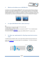
3.
Which are the differences to HIPERFACE®?
Compared to the hybrid interface HIPERFACE®, which provides process data as analogue
Sine and Cosine signals HIPERFACE DSL® exports evaluated positions. Therefore beside
the A/D conversion also the evaluation of the drive controller is not necessary. Furthermore
HIPERFACE DSL® offers more diagnostic possibilities. Different operating parameters (such
as temperature and revolution) are recorded in the encoder and visualized in a histogram.
4.
Is a special HIPERFACE DSL® cable necessary?
No.
A standard servo motor power cable (4+2+2) can be used.
4 x motor power, 2 x brake, 2 x DSL
A winding temperature sensor can also be transmitted via DSL®. For more details please
see the corresponding Whitepaper.
All important cable manufacturers already offer HIPERFACE DSL® compliant cable.
5.
Are there any requirements for the plug connection (on motor
side)?
A standard IntercontecM23 or M17 can be used. Place the DSL-wires symmetrical to the
power-wire (Pinout) and use a short length of the unshielded pin. For further information
please see Whitepaper.
Page 4
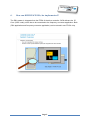
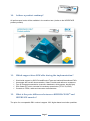
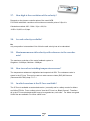
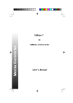
6.
How can HIPERFACE DSL® be implemented?
The DSL-master is integrated into the FPGA of the drive controller. SICK delivers the IPCore (VHDL code), which has to be connected to the frequency converter application. Both
(DSL-application and frequency converter application) can be stored in one FPGA- chip.
Page 5
7.
Is there a license fee to be paid?
The HIPERFACE DSL® master costs once approx. 800,-EUR and can be used as often as
needed. Updates are free of charge.
8.
What does the HIPERFACE DSL® IP-Core do?
He automatically synchronizes himself to the controller pulse. The IP-Core (Intellectual
Property Core) codes and decodes the communication to and from the DSL-encoder. He
stores synchronously to the controller pulse the measuring values (position and speed).
Additional information (besides others winding temperature, histogramme data) are also
available.
9.
Which cycle time can be realized with HIPERFACE DSL®?
The cycle time (SYNC) can be chosen. The protocol aligns the data packages automatically
to the selected controller pulse. The highest possible pulse for position updates is 12,1µs.
longer pulses are steplessly adjustable.
For further information please see HIPERFACE DSL manual (Document 8017596) chap.:1.
Page 6
10.
Is there a product roadmap?
All performance levels will be available in the medium term (similar to the HIPERFACE
product portfolio)
11.
12.
Which support does SICK offer during the implementation?
World wide support by SICK Drives&Control-Team and national/international PM`s
Homepage with current documentation, Video-Tutorials and reference customers
Free of charge documentation (manuals, datasheets, white papers, benefit-flyer)
DSL-Starter KIT which includes all necessary accessories (TP2=718,-EUR)
Contacts to FPGA, cable and connector manufacturers
What is the price difference between a HIPERFACE DSL® and
HIPERFACE encoder?
The price for a comparable DSL version is approx. 20% higher based on similar quantities.
Page 7
13.
Which safety integrity level/performance level can be reached?
If all specifications are observed which are listed in the HIPERFACE DSL safety manual
(Document 8017596) a safety related function chain is suitable for:
SIL2 according EN62061 and IEC 61508 and
Pl d according EN ISO 13849-1
or
SIL3 according EN62061 and IEC 61508 and
Pl e according EN ISO 13849-1
A possible classification depends on the used DSL motor feedback system.
14.
How high is the first error detection time for a safety function?
The error reaction time of a safety function is 200µs from encoder to signal to the application.
15.
For which basic conditions is the determined PFH-value valid?
By 60°C / with an error rate 1:100 on the cable
16.
Regulations for the mechanical interface regarding the expected
SIL / Pl?
The exact observation of the mounting instruction is mandatory.
It has to be secured that the mounting is only done by instructed and qualified staff.
ACHTUNG
For further information please see HIPERFACE DSL safety manual (Document 8017596)
chap.: 7.3.4 and user manual 8014404
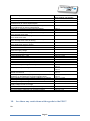
17.
Which error assumptions have been assumed?
The following table lists all assumed error assumptions. For more detailed information please
see HIPERFACE DSL safety manual (Document 8017596) chap.: 7.5.1
Page 8
Error assumption
Short-circuits between any two leads
Break in any leads
Input or output stuck at 0 or 1, separately or
simultaneously at various inputs/outputs
Interruption or high resistance status, separately
or simultaneously at various inputs/outputs
Reduction or increase in signal output amplitudes
Oscillation of one or various outputs
Loss of the mechanical coupling encoder housing/
motor housing when static
Loss of the mechanical coupling encoder shaft/
motor shaft when static
Loss of the mechanical coupling encoder housing/
motor housing when motor is running
Loss of the mechanical coupling encoder shaft/
motor shaft when motor is running
Loss of the measuring element
Failure of the sender diode in the encoder
Static output signals of one or various outputs
within the supply voltage
Alteration of the signal waveform
Communication error – repetition
Communication error – loss
Communication error – insertion
Communication error - incorrect sequence
Communication error - incorrect data
Communication error – delay
Internal position processing: overall or partial error in the function
Internal position processing: break in internal connections
Internal position processing: short-circuit between any two
internal connections
Internal position processing: input or output stuck at 0 or 1,
separately or simultaneously at various inputs/outputs
Internal position processing: parasitic oscillations on outputs
Internal position processing: altered internal analog level
Internal position processing: undiscovered hardware error
Permitted encoder
supply voltage too low or too high
Operation within unauthorized temperature ranges
Operation with incorrect user parameterization
Incorrect interface addressing in multi-axis systems
18.
Error identification/
error control, see chapter
7.5.2.1
7.5.2.1
7.5.2.1
7.5.2.1
7.5.2.1
7.5.2.1
7.5.2.7
7.5.2.6
7.5.2.7
7.5.2.6
7.5.2.1
7.5.2.1
7.5.2.2
7.5.2.2
7.5.2.2, 7.5.2.3
7.5.2.2, 7.5.2.3
7.5.2.2, 7.5.2.3
7.5.2.2, 7.5.2.3
7.5.2.2, 7.5.2.3
7.5.2.7, 7.5.2.5
7.5.2.1, 7.5.2.2, 7.5.2.3, 7.5.2.4,
7.5.2.5
7.5.2.1, 7.5.2.2, 7.5.2.3, 7.5.2.4,
7.5.2.5
7.5.2.1, 7.5.2.2, 7.5.2.3, 7.5.2.4,
7.5.2.5
7.5.2.1, 7.5.2.2, 7.5.2.3, 7.5.2.4,
7.5.2.5
7.5.2.1, 7.5.2.2
7.5.2.1, 7.5.2.2
7.5.2.2, 7.5.2.3, 7.5.2.4, 7.5.2.5
7.5.2.1
7.5.2.1
7.5.2.8
7.5.2.8, 7.5.3
Are there any restrictions with regards to the PELV?
No.
Page 9
19.
Which limits of overvoltage/under voltage have to be observed?
An error messages occurs by nominal under 6,8V and over 12,2V. There is no active switch
off.
20.
How high is the resolution of the position value?
The resolution of the position value depends on the individual product, please see product
information of the relevant MFB
EKSEKM36 up to 20bit/revolution, plus 12 bit with multiturn
EFS/EFM50 up to 23bit/revolution, plus 12 bit with multiturn
21.
How high is the resolution of the safe position?
The resolution of the safe position value (chanal2) depends on the product. Therefor please
consider the relevant product information.
Example: EKS/EKM36 = 9Bit
22.
How high is the latency of the position value?
The latency is 10,5µs with 100m cable.
23.
How big is the timely jitter of the position value?
The timely jitter is <100ns.
Page
10
24.
Must a run time compensation be done?
No.
The IP Core compensates the run time automatically.
25.
How high is the linearity (integral + differential)?
The linearity is depending on the product and can be looked up in the product information of
the corresponding motor feedback system.
Example EKS/EKM36 +/-100'' (angle second)
26.
1.
2.
How can the position be read out?
• Reset IP-Core and switch on power supply for encoder
• Enable DSL output, ""SYS_CTRL""-->01h
3.
• Wait for ""LINK"" --> Encoder is ready. Cyclic read out of register 03h,
unitl Bit 7 is set
4.
• Check "Online Status D". Value 10X3h ("X" toggels between 0,4,8,C), if
the value differs there is a starting error go back to point 1.
5.
• Read position. Register 10h...14h
Page
11
27.
How high is the resolution of the velocity?
Depends on the chosen controller pulse of the used MFB.
For EKx36 with 20bit resolution and a minimum controller pulse of 15µs it is
Calculation method: 360° / 20bit / 15µs = 22,8°/s
1LSB = 22,88°/s or 3,8rpm
28.
Is a safe velocity available?
No
only one position is transmitted. Out of this the safe velocity has to be calculated.
29.
Maximum measurable velocity with reference to the encoder
axis?
The maximum revolution of the motor feedback system is:
Singleturn 12.000rpm, Multiturn 9.000rpm.
30.
How to read out winding temperature sensor ?
The temperature resistance is digitalized and exported vie DSL. The resistance value is
stored in the IP Core. This can be read out under resource index (RID) 200 hex see
(Document 8017596) chap.:7.2.7.1
31.
In which versions is the IP Core available?
The IP Core is available as a standard version (non safe) and in a safety version for Altera
and Xilinx FPGA`s. From a safety point of view the IP Core is a „Black Channel“. Therefore
all in the IP Core calculated values have to be regarded as „none safe”. For Altera encrypted
VHDL files are available. For Xilinx a NGC-core.
Page
12
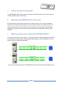
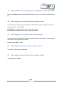
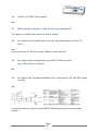
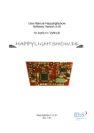
32.
How much space does the DSL IP Core need?
Example IP Core V1.06
33.
Can customers modify the IP Core?
Only interface blocks are open and can be modified.
34.
Are tools for the test of the IP Cores available (Test unit, TestSW)?
PGT-11-S (Matr. Nr. 1057324) can be used as encoder in the slave-mode.
35.
Can the DSL IP Core be instantiated more than once?
Yes
But only one IP Core per motor feedback system.
Page
13
36.
Is there a VHDL-Test bench?
No
37.
With which frequency is the IP-Core synchronized?
The frequency is 75MHz with a maximum Jitter of 100ppm.
38.
Are there special limitations for the implementation of the IP
Core?
Yes
A timing constraint of 13ns for the pulse (75MHz) must be observed.
39.
Are there any manufacturer specific IP-blocks used
(e.g. Microblaze or Nios)?
No
40.
Are there any recommendations for components for the DSL input
circuit?
Yes
Further information you can find in the HIPERFACE DSL manual (Document 8017596)
chapter 3.
Page
14