1
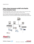
Operating Instructions
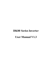
Topclean S CPC30
Automation of pH/Redox Measurements
BA 235C/07/en/11.04
51504339
Software version 1.20 or later
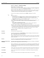
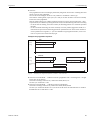
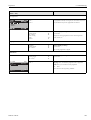
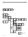
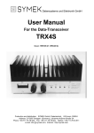
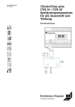
Brief overview
Topclean S
Brief overview
C07-CPC30xxx-16-12-00-de-001.eps
A
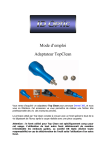
→ page 11 ff. Installation conditions: Mounting types, max. installation distances, assembly installation.
▼
B
→ page 13 ff. Dimensions and installation of the Topclean system
▼
C
→ page 17 ff. Electrical connection of necessary and optional components of the Topclean system
▼
D
→ page 33 ff. Pneumatic connection of the system
▼
E
→
→
→
→
page 42 ff.
page 48 ff.
page 56 ff.
page 112 ff.
Operation
Commissioning
Configuration
Calibration
▼
F
→ page 124 ff. Troubleshooting
→ page 134 ff. Spare parts
▼
→ page 148 ff. Technical data
2
Endress+Hauser
TopCal S CPC 300
Table of Contents
1
Safety instructions . . . . . . . . . . . . . . . . . . . 5
1.1
1.2
1.3
1.4
1.5
Designated use . . . . . . . . . . . . . . . . . . . . . . . . . . . .
Installation, commissioning, operation . . . . . . . . . .
Operational safety . . . . . . . . . . . . . . . . . . . . . . . . . .
Return . . . . . . . . . . . . . . . . . . . . . . . . . . . . . . . . . . .
Safety symbols . . . . . . . . . . . . . . . . . . . . . . . . . . . . .
2
Identification . . . . . . . . . . . . . . . . . . . . . . . . 8
2.1
2.2
2.3
Instrument designation . . . . . . . . . . . . . . . . . . . . . . 8
2.1.1 Nameplate . . . . . . . . . . . . . . . . . . . . . . . . . 8
2.1.2 Product structure . . . . . . . . . . . . . . . . . . . . 9
Scope of delivery . . . . . . . . . . . . . . . . . . . . . . . . . . 10
Certificates and approvals . . . . . . . . . . . . . . . . . . . 10
3
Installation . . . . . . . . . . . . . . . . . . . . . . . . . 11
3.1
3.2
Incoming acceptance, transport, storage . . . . . . . .
Installation conditions . . . . . . . . . . . . . . . . . . . . . .
3.2.1 Installation dimensions . . . . . . . . . . . . . . .
3.2.2 Assembly mounting . . . . . . . . . . . . . . . . . .
Installation instructions . . . . . . . . . . . . . . . . . . . . .
3.3.1 Measuring system . . . . . . . . . . . . . . . . . . .
3.3.2 Wall mounting . . . . . . . . . . . . . . . . . . . . .
3.3.3 Post mounting and panel mounting . . . . . .
Installation check . . . . . . . . . . . . . . . . . . . . . . . . .
3.3
3.4
5
5
5
6
6
11
11
12
12
13
13
13
15
16
4.3.4
4.4
4.5
4.6
4.7
CPA473 / 474 assemblies with
pneumatic limit switches . . . . . . . . . . . . . .
4.3.5 CPA473 / 474 assemblies with
inductive limit switches . . . . . . . . . . . . . . .
Connection diagram Non-Ex . . . . . . . . . . . . . . . . .
Connection compartment sticker CPG30 . . . . . . . .
Connection compartment sticker Mycom . . . . . . . .
Post connection check . . . . . . . . . . . . . . . . . . . . . .
5
Operation . . . . . . . . . . . . . . . . . . . . . . . . . . 42
5.1
5.2
Display and operating elements . . . . . . . . . . . . . . .
5.1.1 Display reading/symbols . . . . . . . . . . . . . .
5.1.2 Key assignment . . . . . . . . . . . . . . . . . . . . .
5.1.3 Operation of the service switch . . . . . . . . .
5.1.4 Measuring menus . . . . . . . . . . . . . . . . . . .
5.1.5 Data log . . . . . . . . . . . . . . . . . . . . . . . . . .
5.1.6 Operation access authorisation . . . . . . . . . .
5.1.7 Description of the menu editor types . . . . .
5.1.8 Factory settings . . . . . . . . . . . . . . . . . . . . .
Replaceable memory . . . . . . . . . . . . . . . . . . . . . . .
6
Commissioning . . . . . . . . . . . . . . . . . . . . 48
6.1
Special features for measurement with
digital sensors with Memosens technology . . . . . . . 48
Special features for measurement with
ISFET sensors . . . . . . . . . . . . . . . . . . . . . . . . . . . . 49
Installation and function check control . . . . . . . . . 49
Switching on the device . . . . . . . . . . . . . . . . . . . . 49
6.4.1 First commissioning . . . . . . . . . . . . . . . . . . 50
First start up . . . . . . . . . . . . . . . . . . . . . . . . . . . . . 51
6.5.1 Configuring Clean programme
(via automatic function) . . . . . . . . . . . . . . . 54
Description of functions . . . . . . . . . . . . . . . . . . . . . 56
6.6.1 Set up 1 – Sensor input . . . . . . . . . . . . . . . 56
6.6.2 Set up 1 – Display . . . . . . . . . . . . . . . . . . . 57
6.6.3 Set up 1 – Access codes . . . . . . . . . . . . . . 58
6.6.4 Set up 1 – Current outputs . . . . . . . . . . . . . 59
6.6.5 Set up 1 – Relays . . . . . . . . . . . . . . . . . . . . 61
6.6.6 Set up 1 – Temperature . . . . . . . . . . . . . . . 62
6.6.7 Set up 1 – Alarm . . . . . . . . . . . . . . . . . . . . 65
6.6.8 Set up 1 – Hold . . . . . . . . . . . . . . . . . . . . . 66
6.6.9 Set up 1 – Calibration . . . . . . . . . . . . . . . . 67
6.6.10 Set up 2 – Data log . . . . . . . . . . . . . . . . . . 72
6.6.11 Set up 2 – Check systems . . . . . . . . . . . . . 73
6.6.12 Set up 2 – Controller settings . . . . . . . . . . . 74
6.6.13 Set up 2 – Limit switch . . . . . . . . . . . . . . . 86
6.6.14 Set up 2 - Controller quick adjustment . . . . 87
6.6.15 Set up 2 – Topclean S . . . . . . . . . . . . . . . . 88
6.6.16 Set up 2 – Chemoclean . . . . . . . . . . . . . . . 98
6.6.17 Manual operation . . . . . . . . . . . . . . . . . . 102
6.6.18 Diagnosis . . . . . . . . . . . . . . . . . . . . . . . . . 104
6.6.19 Calibration . . . . . . . . . . . . . . . . . . . . . . . 112
6.2
4
Wiring and pneumatic connection
of Topclean S . . . . . . . . . . . . . . . . . . . . . . . 17
6.3
6.4
4.1
Connection of required electric lines . . . . . . . . . . .
4.1.1 Power supply and communication line
of Mycom and CPG30 . . . . . . . . . . . . . . . .
4.1.2 CYR10 injector . . . . . . . . . . . . . . . . . . . . .
4.1.3 Analogue pH glass electrodes and
ISFET sensors . . . . . . . . . . . . . . . . . . . . . .
4.1.4 Digital pH sensors with
Memosens technology . . . . . . . . . . . . . . . .
Connecting optional electric lines . . . . . . . . . . . . .
4.2.1 Mycom current outputs and relays . . . . . . .
4.2.2 External inputs (PCS to CPG30) and
outputs (CPG30 to PCS) . . . . . . . . . . . . . .
4.2.3 External inputs PCS to Mycom . . . . . . . . .
4.2.4 External valve for sealing water,
steam, etc. to CPG30 . . . . . . . . . . . . . . . .
4.2.5 Inductive limit position switches . . . . . . . .
Topclean S hosing . . . . . . . . . . . . . . . . . . . . . . . . .
4.3.1 Compressed air . . . . . . . . . . . . . . . . . . . . .
4.3.2 CPA471 / 472 / 475 assemblies with
pneumatic limit position switches . . . . . . .
4.3.3 CPA471 / 472 / 475 assemblies with
inductive limit position switches . . . . . . . .
17
6.5
17
19
6.6
4.2
4.3
Endress+Hauser
20
25
26
26
28
29
30
31
33
33
34
35
36
37
38
39
40
41
42
42
42
43
44
44
45
46
46
47
3
Table of Contents
TopCal S CPC 300
7
Maintenance . . . . . . . . . . . . . . . . . . . . . . 119
8.6
7.1
8.7
7.4
7.5
7.6
Sensor cleaning and inspection . . . . . . . . . . . . . .
7.1.1 External cleaning of the sensor . . . . . . . .
7.1.2 Inspecting the sensor . . . . . . . . . . . . . . .
7.1.3 Maintenance of digital sensors . . . . . . . .
Manual calibration . . . . . . . . . . . . . . . . . . . . . . .
Maintenance of cables, connections and
power supply lines . . . . . . . . . . . . . . . . . . . . . . .
Maintenance of the process assembly . . . . . . . . .
Maintenance of the control unit CPG30 . . . . . . .
Maintenance of the CYR10 injector . . . . . . . . . .
8
8.1
7.2
7.3
8.2
8.3
8.4
8.5
4
8.8
8.9
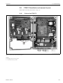
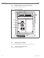
CPG30 Installation and removal of parts . . . . . . .
8.6.1 Device view CPG30 . . . . . . . . . . . . . . .
Detailed plans of CPG30 . . . . . . . . . . . . . . . . . . .
8.7.1 Terminal wiring diagram CPG30 . . . . . . .
8.7.2 Pneumatics and hydraulics
CPG30 non-Ex . . . . . . . . . . . . . . . . . . .
8.7.3 CYR10 injector . . . . . . . . . . . . . . . . . . . .
Replacing the device fuses . . . . . . . . . . . . . . . . . .
Disposal . . . . . . . . . . . . . . . . . . . . . . . . . . . . . . .
9
Accessories . . . . . . . . . . . . . . . . . . . . . . . 142
Troubleshooting . . . . . . . . . . . . . . . . . . 124
10
Technical data . . . . . . . . . . . . . . . . . . . . . 148
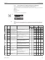
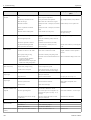
Troubleshooting instructions . . . . . . . . . . . . . . .
8.1.1 Error number list: Trouble-shooting
and configuration . . . . . . . . . . . . . . . . .
8.1.2 Process-specific errors . . . . . . . . . . . . . . .
8.1.3 Instrument-specific error . . . . . . . . . . . .
Response of outputs to errors . . . . . . . . . . . . . . .
8.2.1 Current output behaviour . . . . . . . . . . . .
8.2.2 Response of contacts to errors . . . . . . . .
8.2.3 Response of contacts to power failure . . .
8.2.4 Assembly behaviour . . . . . . . . . . . . . . . .
CPM153 spare parts . . . . . . . . . . . . . . . . . . . . . .
CPM153 Installation and removal of parts . . . . . .
8.4.1 Device view CPM153 . . . . . . . . . . . . . .
8.4.2 Codings . . . . . . . . . . . . . . . . . . . . . . . . .
CPG30 Spare parts . . . . . . . . . . . . . . . . . . . . . . .
10.1
10.2
10.3
10.4
10.5
10.6
Input . . . . . . . . . . . . . . . . . . . . . . . . . . . . . . . . .
Output . . . . . . . . . . . . . . . . . . . . . . . . . . . . . . . .
Accuracy . . . . . . . . . . . . . . . . . . . . . . . . . . . . . .
Ambient conditions . . . . . . . . . . . . . . . . . . . . . . .
Process conditions . . . . . . . . . . . . . . . . . . . . . . .
Mechanical data . . . . . . . . . . . . . . . . . . . . . . . . .
11
Appendix . . . . . . . . . . . . . . . . . . . . . . . . . 155
11.1
11.2
11.3
11.4
Operating matrix . . . . . . . . . . . . . . . . . . . . . . . .
Connection example . . . . . . . . . . . . . . . . . . . . .
Wiring example for external cleaning trigger . . .
Buffer tables . . . . . . . . . . . . . . . . . . . . . . . . . . . .
12
Index . . . . . . . . . . . . . . . . . . . . . . . . . 171
120
120
121
121
121
122
122
123
123
124
125
129
131
132
132
132
133
133
134
135
135
136
136
138
138
138
138
139
140
141
141
148
149
151
152
152
152
155
168
169
170
Endress+Hauser
Topclean S
1 Safety instructions
1
Safety instructions
1.1
Designated use
Topclean S CPC30 is a fully automatic measuring and cleaning system for pH and redox
measurements.
The system is supplied complete with power supply cables and bottle hose.
The Ex version of the Topclean S CPC30 allows operation even in explosive atmospheres.
The manufacturer is not liable for damage caused by improper or non-designated use.
1.2
Installation, commissioning, operation
Note the following points:
• If the system is used improperly or other than for its designated use, it may pose a hazard, e.g.
due to improper connection.
• Installation, electrical connection, commissioning, operation and maintenance of the measuring
system must therefore be carried out exclusively by trained specialists authorised by the system
operator.
• Technical personnel must have read and understood these operating instructions and must adhere
to them.
• Always follow the regulations in your country pertaining to the opening and repairing of electrical
instruments.
1.3
#
Operational safety
Warning!
If the device is used for any application other than those described in these Operating Instructions,
it may lead to unsafe and improper functioning of the measuring system and is therefore not permitted.
The instruments have been designed and tested according to the state of the art and left the factory
in perfect functioning order. The instruments meet all the prevailing regulations and EC directives
- see "Technical data".
However, always pay attention to the following points:
• Measuring systems used in Ex areas have a separate document (XA 236C/07/a3) which forms a
component part of these Operating Instructions. Always follow the installation regulations and the
- partly deviating - connection data in the Ex documentation as well. You can find the following
symbols on the front page of the additional Ex documentation (depending on approval and test
centre (0 Europe, 2 USA, 1 Canada).
• The measuring device complies with the general safety requirements in accordance with
EN 61010, the EMC requirements of EN 61326, and NAMUR Recommendation NE 21, 1998.
• The manufacturer reserves the right to change the technical data in line with technical progress
at any time. You can obtain information on the current version of these Operating Instructions
and possible additions from your sales centre.
Endress+Hauser
5
1 Safety instructions
Topclean S
Fail-safety
This instrument has been checked for electromagnetic compatibility in industrial use according to
applicable European directives. It is protected against electromagnetic interference by appropriate
design measures.
#
Warning!
Protection against interference as specified above is valid only for an instrument connected
according to the instructions in these Operating Instructions.
1.4
Return
If the devices have to be repaired, please return them cleaned to the sales centre responsible (copy
second last page of these Operating Instructions). For returns please use the original packaging.
Please enclose a completed copy of the "Declaration of contamination" with the packaging and
transportation documents.
No repair without completed "Declaration of contamination".
1.5
Safety symbols
To avoid damage to persons and property, always pay attention to the safety instructions in these
Operating Instructions. The following symbols are used to provide you with important information:
General safety instructions
Symbol
#
"
!
6
Meaning
Warning!
This symbol alerts you to hazards which could cause serious injuries as well as damage to
the instrument if ignored.
Caution!
This symbol alerts you to possible faults which could arise from incorrect operation. They
could cause damage to the instrument if ignored.
Note!
This symbol indicates important items of information.
Endress+Hauser
Topclean S
Electrical symbols
1 Safety instructions
Symbol
%
&
)
*
+
/
b
Meaning
DC voltage
A terminal at which DC voltage is applied or through which DC flows.
AC voltage
A terminal at which (sine-form) AC voltage is applied or through which AC flows.
Ground connection
A grounded terminal, which, from the user's point of view, is already grounded using a
grounding system.
Protective earth terminal
A terminal which must be grounded before other connections may be set up.
Equipotential connection
A connection which must be connected to the grounding system of the equipment. This
can be, for example, a potential matching line of a star-shaped grounding system, depending on national or company practice.
Protective insulation
The equipment is protected with an additional insulation.
Alarm relay
Input
Output
Endress+Hauser
7
2 Identification
Topclean S
2
Identification
2.1
Instrument designation
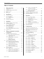
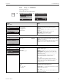
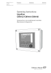
2.1.1
Nameplate
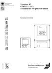
The two Topclean S system components CPM153 transmitter and CPG30 control unit have
individual nameplates.
8
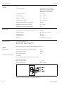
ƒig. 1:
Nameplate example for the transmitter Mycom S CPM153.
ƒig. 2:
Nameplate example for the control unit CPG30.
Endress+Hauser
Topclean S
2 Identification
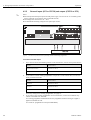
2.1.2
Product structure
Basic equipment:
Control unit CPG30, transmitter Mycom S with 6 relays and DAT module, CYR10 injector,
multihose (5 m / 16.41 ft), 1 empty bottle, bottle hose (2 m / 6.56 ft), communication/power
supply cable Mycom S – CPG30 (5 m / 16.41 ft)
Certificates
A
G
S
O
P
T
Basic equipment: non-Ex
With ATEX approval II (1) 2G EEx em ib[ia] IIC T4
With CSA approval Cl. I, Div. 2, Sensor IS Cl. I Div. 1
With FM approval CI. I, Div. 2, with NI input and output circuits, sensor IS Cl. I Div. 1
With FM approval CI. I, Div. 2, with NI input and output circuits
With TIIS approval
Control for external valves
0
1
2
Basic equipment: no additional valves controllable
Control for 1 external valve, non-Ex
Control for 1 external valve, Ex
Measurement inputs Mycom S
1
2
5
1 measuring circuit for glass electrodes, pH/redox and temperature
1 measuring circuit for glass electrodes/ISFET sensors, pH/redox and temperature
1 measuring circuit for digital pH sensors (Memosens) and temperature
Measurement output Mycom S
A
B
C
D
E
2 current outputs 0/4 ... 20 mA, passive (Ex and non-Ex)
2 current outputs 0/4 ... 20 mA, active (non-Ex)
HART with 2 current outputs 0/4 ... 20 mA, passive
HART with 2 current outputs 0/4 ... 20 mA, active
PROFIBUS-PA, without current outputs
Power supply
0
1
8
230 V AC
100 ... 115 V AC (jumper in CPG30, universal power supply unit in CPM153)
24 V AC / DC
Language versions
A
B
C
D
E
F
E/D
E/F
E/I
E / ES
E / NL
E/J
Cable connection
0
1
3
4
Cable glands M 20 x 1.5
Cable glands NPT ½"
Cable glands M 20 x 1,5, PROFIBUS-PA M12 plug
Cable glands NPT 1/2", PROFIBUS-PA M12 plug
Length of multihose
0
8
5m
10 m
Additional equipment
0
Without additional equipment
Configuration
A
CPC30-
Endress+Hauser
Factory setttings
Complete order code
9
2 Identification
Topclean S
2.2
Scope of delivery
The scope of delivery of the cleaning and calibration system Topclean S comprises:
• 1 Transmitter Mycom S CPM153
• 1 Control unit CPG30
• 1 Multihose
• 1 Bottle for cleaning fluid
• 1 Communications/power supply cable CPG30 / Mycom S CPM153,
• 1 Pressure reduction valve with manometer
• 1 Instrument identification card
• Accessories (s. chap. 9)
• 1 Operating Instructions 235C/07/en
• Ex versions:
1 Safety instructions for electrical equipment in hazardous areas, XA 236C/07/a3
• Versions with HART communication:
1 Operating instructions Field communication with HART, BA 301C/07/en
• Versions with PROFIBUS interface:
1 Operating instructions Field communication with PROFIBUS PA/DP, BA 268C/07/en
2.3
Certificates and approvals
Declaration of Conformity
The product complies with the legal demands of the harmonised European standards.
Endress+Hauser certifies the compliance with the standards by using the 4 sign.
10
Endress+Hauser
Topclean S
3 Installation
3
Installation
3.1
Incoming acceptance, transport, storage
• Make sure the packaging is undamaged!
Inform the supplier about damage to the packaging.
Keep the damaged packaging until the matter has been settled.
• Make sure the contents are undamaged!
Inform the supplier about damage to the delivery contents.
Keep the damaged products until the matter has been settled.
• Check that the scope of delivery is complete and agrees with your order and the shipping
documents.
• The packaging material used to store or to transport the product must provide shock protection
and humidity protection. The original packaging offers the best protection.
Also, keep to the approved ambient conditions (see "Technical data").
• If you have any questions, please contact your supplier or your sales centre responsible (see back
page of these Operating Instructions).
3.2
!
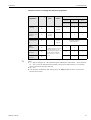
Installation conditions
Note!
Always install the transmitter and the control unit so that the cable entries point downwards.
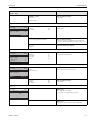
The components can be installed using the following methods:
Device
Wall mounting
Post/
pipe installation
Panel mounting
Control unit CPG30
Mounting kit contained in
scope of delivery.
See fig. 6.
not applicable
not applicable
Mycom S CPM153,
covered
Required:
2 screws dia. 6 mm
2 rawl plugs dia. 8 mm
Mounting kit contained in
scope of delivery. See fig. 9.
Mounting kit contained in
scope of delivery.
See fig. 9.
Mycom S CPM153,
outdoors
If installed outdoors, weather protection cover
CYY101 required
(see Accessories).
Weather protection cover
CYY101 and 2x round post
fixtures required
(see Accessories).
not usual
Notes on installation
• The transmitter CPM153 is normally used as a field device.
• The transmitter CPM153 can be fixed to a vertical or horizontal pipe using the supplied mounting
kit. For outdoor installation, a weather protection cover CYY101 is required. It can be fitted to
the field device using all kinds of fixtures (refer to "Accessories").
Endress+Hauser
11
3 Installation
Topclean S
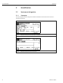
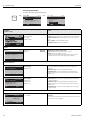
3.2.1
Installation dimensions
You can find the dimensions and lengths of the devices in the figures of the installation instructions
on page 13 ff.
The maximum horizontal and vertical installation distances are shown in the figure below.
C07-CPC30xxx-17-12-00-en-001.eps
ƒig. 3:
3.2.2
Maximum horizontal and vertical installation distances
Assembly mounting
• Glass electrode: Install the assembly at an angle of at least 15° from the horizontal (page 12 ff.).
• ISFET sensor: When using an ISFET sensor there are, in principle, no restrictions to the
installation. An installation angle between 0° and 180° is, however, recommended.
A
B
15°
15°
C07-CPA472xx-17-07-00-xx-002.eps
ƒig. 4:
A
B
12
Installation angle
Glass electrodes: installation angle at least 15° from the horizontal
ISFET sensors: recommended 0 ... 180°, upside-down installation possible
Endress+Hauser
Topclean S
3 Installation
3.3
Installation instructions
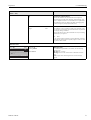
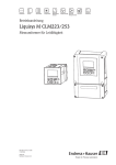
3.3.1
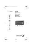
Measuring system
C07-CPC30xxx-14-03-xx-xx-001.eps
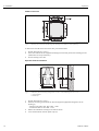
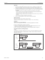
ƒig. 5:
Fully automatic measuring system (example)
A
Message and control signals: assembly position, programme status, assembly movement, programme stop
B
Hold input, six relay contacts, 2 current outputs 0/4 ... 20 mA
1
Cleanfit P assembly
8
CPR40 rinse block (optional)
2
Mycom S CPM153 transmitter
9
Additional valve
3
CPG30 control unit
10
Cleaner
4
Power supply for Mycom S CPM153
11
Electric line
5
Communication / power cable
12
Compressed air
6
Multi hose
13
Liquids, cleaning mixture
7
CYR injector
3.3.2
"
Endress+Hauser
Wall mounting
Caution!
• Check that the temperature does not exceed the maximum permitted operating temperature
range (–20° ... +60°C). Install the devices in a shady location. Avoid direct sunlight.
• Always mount the devices horizontally so that the cable entries and hose connections point
downwards.
13
3 Installation
Topclean S
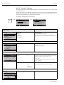
CPG30 control unit
C07-CPC300xx-06-12-00-en-001.eps
ƒig. 6:
Mounting the control unit CPG30 using wall mounting kit (contained in scope of delivery)
To mount the CPG30 control unit at the wall, proceed as follows:
1.
2.
3.
Prepare drill holes acc. to fig. 6.
Screw the elements of the supplied wall fixing kit to the back panel of the housing (screws
contained in the scope of delivery).
Fix the housing to the wall.
Mycom S CPM153 transmitter
Ø 8 / 0.31
247 / 9.72
154 / 6.06
1
2
142 / 5.59
167 / 5.57
100 / 3.94
mm / inch
C07-CPM153xx-11-00-08-en-001.eps
ƒig. 7:
1.
2.
3.
4.
14
Dimensions for wall mounting: Fixing screw: Ø 6 mm / 0.24", Wall plug: Ø 8 mm / 0.31"
1: Fixing drillholes
2: Plastic caps
Prepare drill holes acc. to fig. 7.
Push the two fixing screws from the front through the appropriate fixing bores in the
housing (1).
– Fixing screws (M6): max. Ø 6.5 mm / 0.26"
– Screw head: max. Ø 10.5 mm / 0.41"
Mount the transmitter housing on the wall as shown.
Cover the drill holes with the plastic caps (2).
Endress+Hauser
Topclean S
3 Installation
3.3.3
Post mounting and panel mounting
Transmitter Mycom S CPM153
Mount the parts of the mounting kit (see
accompanying figure) at the back of the housing
as depicted in fig. 9.
Required mounting cutout for panel mounting:
161 x 241 mm / 6.34" x 9.49".
Installation depth: approx. 134 mm / 5.28".
Maximum pipe diameter: 70 mm / 2.76".
ƒig. 8:
ƒig. 9:
"
Mounting kit Mycom S CPM153
Panel mounting (1) and post mounting horizontal (2) and vertikal (3) for Mycom S CPM153
Caution!
For outdoor use, the weather protection cover CYY101 is required (see fig. 10 and accessories).
C07-CPM153xx-11-00-01-xx-001.eps
ƒig. 10:
Endress+Hauser
Post mounting for CPM153 with weather protection cover CYY101.
15
3 Installation
Topclean S
3.4
16
Installation check
Installation
Remarks
Are the measuring point number and the labelling correct?
Visual inspection
Process environment/conditions
Remarks
Is the transmitter protected against rainfall and direct sunlight?
For outdoor use, the CYY101 weather
protection cover is required (see "Accessories").
Is the control unit protected against rainfall and direct sunlight?
Avoid direct sunlight.
Endress+Hauser
Topclean S
4 Wiring and pneumatic connection of Topclean S
4
Wiring and pneumatic connection of Topclean S
Connection of the Topclean S system is carried out in several steps:
1.
2.
3.
Connecting required electric lines
Connecting optional electric lines
Connecting hoses for liquids and compressed air
4.1
Connection of required electric lines
4.1.1
Power supply and communication line of Mycom and CPG30
C07-CPC30xxx-04-12-00-xx-009.eps
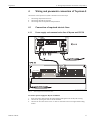
ƒig. 11:
Power supply and communication cable
To connect power supply for Mycom S CPM153
1.
2.
3.
Endress+Hauser
Insert the power cable through the right-hand Pg cable gland into the Mycom housing.
Connect the yellow-green wire to the PE terminal.
Connect the two other wires to the "L" and "N" terminals in the lower right-hand housing
section.
17
4 Wiring and pneumatic connection of Topclean S
Topclean S
To connect power supply for CPG30 control unit (non-Ex)
1.
2.
3.
!
Insert the power cable through a suitable Pg cable gland into the CPG30 housing.
Connect the yellow-green wire to the PE terminal.
Connect the two other wires to the "L+" and "N" terminals (lower terminal block, left).
Note!
In the Ex version, the CPG30 is powered via the communication/power supply cable of the
Mycom S CPM153 (see XA 236C/07/en).
To connect the communication line between Mycom and CPG30
1.
2.
3.
18
Insert the end of the communication cable with the black screen wire through a suitable Pg
cable gland of the Mycom S CPM153.
Insert the other cable end through a Pg cable gland of CPG30.
Connect the wires as follows:
Wire
Mycom terminal
CPG30 terminal
Yellow (YE)
Terminal B
Terminal B
Green (GN)
Terminal A
Terminal A
White (WH)
Terminal L-
Terminal L-
Brown (BN)
Terminal L+
Terminal L+
Black (BK)
PE rail
n.c.
Endress+Hauser
Topclean S
4 Wiring and pneumatic connection of Topclean S
4.1.2
CYR10 injector
C07-CPC30xxx-04-12-00-xx-010.eps
ƒig. 12:
1.
2.
Endress+Hauser
Connection of CYR10 injector
Insert the cables of the CYR10 through a suitable Pg cable gland.
Connect the wires as follows:
Wire
CYR10 connection
CPG30 terminal
Positive wire for motive water
Connection 1 of small connector
(in front)
Terminal 47
Negative wire for motive water
Connection 2 of small connector
(in front)
Terminals 48
Positive wire for cleaning agent
Connection 1 of long connector
(in the back)
Terminal 51
Negative wire for cleaning agent
Connection 2 of long connector
(in the back)
Terminal 52
19
4 Wiring and pneumatic connection of Topclean S
4.1.3
Topclean S
Analogue pH glass electrodes and ISFET sensors
Cable types
You require a screened special cable to connect analogue pH/redox electrodes and ISFET sensors.
You can use the following multicore and preterminated cable types:
• CPK1 for electrodes with standard plug-in head GSA and without Pt 100
• CPK9 for electrodes with TOP 68 plug-in heads (ESA / ESS) and Pt 100
• CPK12 for ISFET pH sensors and pH/redox glass electrodes with TOP 68 plug-in heads (ESB) and
Pt 100 / Pt 1000
Electrode connection with PML (symmetrical) or without PML (unsymmetrical)
You can connect the sensor with PML (symmetrically) or without PML (unsymmetrically), note the
following differences
With PML (symmetrical)
Without PML (unsymmetrical)
"Caution!
If the instrument input is without PML, pH
measuring chains connected to assemblies can
be connected without an additional potential
matching pin. If necessary, connect the brown
wire to terminal PE.
With a connection with PML, the line to the
potential matching pin (PML) must be
connected to the potential matching terminal
of the instrument. The PML must always be in
contact with the medium, i.e. immersed in the
buffer solution during calibration.
Benefits of connection with PML
Measurement is easier under difficult ambient
conditions (e.g. strongly flowing or highimpedance media or partially soiled
diaphragm).
Monitoring of the reference electrode by the
SC system (see page 73) is possible.
Disadvantages of connection without
PML
The measuring chain reference system has a
heavier load, meaning that measuring errors in
limiting operating conditions are possible (see
symmetrically high-resistance instrument
input).
Monitoring of the reference electrode by the
SC system (see page 73) is not possible.
!Note!
Do not connect the PML, otherwise there can
be shunt excitations.
!
20
Note!
The instrument is preset for measurement with PML (potential matching line). For measurement
without PML, the setting must be changed accordingly (see page 56, "Select connection type").
Endress+Hauser
Topclean S
4 Wiring and pneumatic connection of Topclean S
Connecting the sensor
"
Caution!
Danger of inaccuracy.
Always protect plugs and terminals against humidity.
1
2
3
4
C07-CPM153xx-00-06-08-xx-002.eps
ƒig. 13:
B
A
Ref PA 12 13 11 S
pH
Ref PA 12 13 11 S
YE*
WH*
GN*
pH
Koax/ WH
coax
BK
CPK9 /
CPK1
Koax/ WH
coax BK
4.
5.
Push the cable gland and the clamping ring over the cable.
Remove the inner insulation.
Loosen the outer screen from the cable and fold it back over the cable gland to establish
contact.
Insert the sensor cable through the cable gland of Mycom S CPM153 and tighten the gland.
If you are using a glass electrode, connect the wires as follows:
BN
YE*
WH*
GN*
1.
2.
3.
Outer screen connection for CPK1 to CPK12 with metal cable gland.
The screen contact is within the cable gland.
BN
PE *
BN
* PE
BN
PA/PM
frei/
d.n.c
C07-CPC300xx-04-06-00-xx-013.eps
ƒig. 14:
Endress+Hauser
Electrode connection
A = symmetrical connection
B = unsymmetrical connection
* not applicable for CPK1 for electrodes without Pt 100
21
4 Wiring and pneumatic connection of Topclean S
Wire
Mycom terminal
Black coax wire
Terminal Ref
White coax wire
Terminal pH
White (WH)
Terminal 13
Yellow (YE)
Terminal 12
Green (GN)
Terminal 11
Brown (BN)
• Connection with PML (A): terminal PA
Make sure that the potential matching pin is always in contact
with medium.
• Connection without PML (B): PE rail
Outer screen
Grounded via metal cable gland
If you are using an ISFET sensor, connect the wires as follows:
A
Ref PA 12 13 11 S
RD
Koax/ WH
coax BK
Ref PA 12 13 11 S
Koax/ WH
coax BK
RD
DRNSRC
B
DRNSRC
YE
WH
GN
CPK12
BN
YE
WH
GN
6.
Topclean S
BN
* PE
* PE
BN
BN
frei/
d.n.c
PA/PM
C07-CPC300xx-04-06-00-xx-014.eps
ƒig. 15:
22
ISFET sensor connection
A = symmetrical connection
B = unsymmetrical connection
Wire
Mycom terminal
Red (RD)
Terminal DRN
Black coax wire
Terminal Ref
White coax wire
Terminal SRC
White (WH)
Terminal 13
Yellow (YE)
Terminal 12
Green (GN)
Terminal 11
Endress+Hauser
Topclean S
4 Wiring and pneumatic connection of Topclean S
Wire
Mycom terminal
Brown (BN)
• Connection with PML (A): PA terminal
Make sure that the potential matching pin is always in contact
with medium.
• Connection without PML (B): PE rail
Outer screen
Grounded via metal cable gland
Cable extension
If a cable extension is necessary, use
• junction box VBM
and the following types of non-terminated measuring cables:
• for CPK1, CPK9:
Cable CYK71
• for CPK12:
Cable CYK12
!Note!
Remove the black plastic semi-conductor
layer (arrow) from the inner coaxial cable.
Each cable type has such a layer.
!
C07-CPC300xx-04-12-00-xx-007.eps
ƒig. 16:
Endress+Hauser
Design of coaxial line
23
4 Wiring and pneumatic connection of Topclean S
Topclean S
Changing the pH input from glass electrode to ISFET sensor
The Topclean S version glass/ISFET (CPC30-xx2xxxxxxx) is factory set for measurement with glass
electrodes.
To adapt the electrical connection for ISFET sensors, please proceed as follows:
1.
2.
3.
Open the lower housing section of the CPM153.
If a glass electrode is connected, remove the wires of the electrode cable.
Remove the "pH" terminal located at the housing cover and replace it by the included terminal
"DRN" / "SRC".
C07-CPM153xx-04-06-06-xx-004.eps
ƒig. 17:
4.
5.
6.
7.
8.
!
pH terminal at the housing cover
Open the housing cover of the CPM153.
On the right side of the housing cover, pull off both ends of the red cable to the pH input (see
fig. 18).
Pin up the jumpers included as shown in fig. 19.
Connect the sensor cable according to the wire assignment for ISFET sensors.
Change the setting "electrode type" in the First start up menu (p. 51) to "ISFET".
Note!
Please switch from ISFET sensor to glass electrode correspondingly.
C07-CPM153xx-04-06-06-xx-002.eps
ƒig. 18:
24
pH input module and pH terminal set in
housing cover with cable (red) for connection
of pH / redox glass electrodes.
C07-CPM153xx-04-06-06-xx-003.eps
ƒig. 19:
pH input module and pH terminal set in
housing cover with jumpers for connection of ISFET
sensors
Endress+Hauser
Topclean S
4 Wiring and pneumatic connection of Topclean S
4.1.4
Digital pH sensors with Memosens technology
Measuring cable
To connect digital sensors with Memosens technology to Mycom S CPM153, you require the
CYK10 Memosens data cable with 2x2 wires, twisted pair, screen and PVC sheath.
1
YE Com B
GN Com A
97
96
WH BN +
88
87
C07-CPM2x3xx-04-06-00-xx-003.eps
ƒig. 20:
1
Design of CYK10 Memosens data cable
Coupling with integrated electronics for connection to the sensor
Connecting the sensor
C07-CPM153xx-04-06-00-xx-015.eps
ƒig. 21:
CPS11D connection with CYK10
Connect the wires as follows:
Endress+Hauser
Wire
Mycom terminal
Yellow (YE)
Terminal 97
Green (GN)
Terminal 96
White (WH)
Terminal 88
Brown (BN)
Terminal 87
Screen
Grounded via metal cable gland
25
4 Wiring and pneumatic connection of Topclean S
Topclean S
4.2
Connecting optional electric lines
4.2.1
Mycom current outputs and relays
C07-CPC300xx-04-06-00-xx-015.eps
ƒig. 22:
Connection of current outputs (example: HART to output 1) and relays (example: alarm and Chemoclean
water)
To connect current outputs
If you want to output measured values to external evaluation devices or a PCS or you are using
HART communication, you can connect these devices to the current outputs 1 and 2 of Mycom S.
In addition, you can output an actuating variable via current output 2.
1.
2.
26
Connect the device to current output 1 as follows:
Wire
Mycom terminal
Positive wire
Terminal 31
Negative wire
Terminal 32
Connect the device to current output 2 as follows:
Wire
Mycom terminal
Positive wire
Terminal 33
Negative wire
Terminal 34
Endress+Hauser
Topclean S
4 Wiring and pneumatic connection of Topclean S
To connect Mycom relays
Mycom S CPM153 has one alarm contact and five additional contacts. Via these five contacts, you
can control controller, limit contactor, water and cleaning agent supply for the Chemoclean
function. To configure the additional contacts, select "Setup 1 > Relays", see page 61.
1.
2.
Connect the alarm contact to terminals "41" and "42".
Connect the additional contacts as follows:
Relay
CPG30 terminal
Relay 1
Terminals 47 and 48
Relay 2
Terminals 57 and 58
Relay 3
Terminals 51 and 52
Relay 4
Terminals 54 and 55
Relay 5
Terminals 44 and 45
The function assignment (controller, limit contactor, etc.) to each relay depends on your
configuration.
When using the NAMUR assignment, for example, functions of the alarm relay and the first
two additional relays are preset (see NAMUR assignment below). Without NAMUR
assignment, you can assign any function to all five additional relays.
!
Note!
• You can assign up to three relays to the controller.
• You can switch the contact type "Active open" / "Active closed" via software.
NAMUR assignment
If you are using the NAMUR assignment (acc. to recommendations of the association for processs
control engineering of the chemical and pharmaceutical industry), the contacts are set to the relays
as follows:
Relays
NAMUR
ALARM
Failure
RELAY 1
Maintenance required
RELAY 2
Function check
on
Terminal
Function check assignment
Function check acc. to NAMUR is active when:
• The sensor is calibrated
• The assembly is in service position.
• Mycom is configured.
• A Topclean cleaning programme is running.
• A Chemoclean programme is running.
• An error occurs which triggers the function check (assignment see error list page 125).
Endress+Hauser
27
4 Wiring and pneumatic connection of Topclean S
4.2.2
!
Topclean S
External inputs (PCS to CPG30) and outputs (CPG30 to PCS)
Note!
• External inputs and outputs require external power supply. You can use the 15 V auxiliary power
supply of Mycom to provide the power (terminals 85/86).
• The voltage must lie between 10 ... 40 V.
• The maximum switching voltage for the optocoupler is 30 V.
C07-CPC30xxx-04-12-00-xx-013.eps
ƒig. 23:
Connection of external control of assembly position and cleaning programmes
To connect external inputs
1.
2.
3.
28
If you want to control the assembly position via an external PCS, connect the inputs as follows:
Control
CPG30 terminal
Position "Measurement"
Terminals 91 and 92
Position "Service"
Terminals 93 and 94
If you want to control cleaning programmes of Topclean S via an external PCS, connect the
binary contacts of CPG30:
Contact
CPG30 terminal
Contact 0
Terminals 81 and 82
Contact 1
Terminals 83 and 84
Contact 2
Terminals 85 and 86
For binary coding of the cleaning programmes, see page 91.
If you want to stop cleaning programmes via an external PCS, connect the automatic stop
control to terminals "87" and "88".
The running programme is finished and no new programme is started as long as a signal is
applied to terminals 87/88.
The Clean Int. programme is interrupted immediately.
Endress+Hauser
Topclean S
4 Wiring and pneumatic connection of Topclean S
To connect external outputs of CPG30 to a PCS
1.
2.
If you want to feed back the assembly position to an external PCS, connect the outputs of
CPG30 as follows:
Feedback
CPG30 terminal
Feedback "Assembly in measurement
position"
Terminals 61 and 62
Feedback "Assembly in service
position"
Terminals 65 and 66
If you want to feed back the status of cleaning programmes to an external PCS, connect the
feedback "Programme running" to terminals "71" and "72".
4.2.3
External inputs PCS to Mycom
C07-CPC300xx-04-06-00-xx-017.eps
ƒig. 24:
Connection of external hold for Mycom
If you want to activate the hold function for Mycom S CPM153 via an external PCS, connect this
input to Mycom terminals 81 and 82.
Endress+Hauser
29
4 Wiring and pneumatic connection of Topclean S
4.2.4
Topclean S
External valve for sealing water, steam, etc. to CPG30
If you are using a Topclean with control for external valves (see nameplate, version
CPC30-x1/2/3/xxxxxxx), you can select the functions "sealing water", "sterilisation" in the
Topclean S cleaning or user programmes.
To assign the valve, select "Setup 2 > Topclean > Config. Topclean". See page 88 ff.
!
Note!
• The external valve is an ordering option. For retrofitting, contact your sales centre.
• The Ex version of Topclean S has a pneumatically controlled valve (see XA236C).
• When using an external valve, you must use the CPR40 rinse block for supply of pressurised
media.
What is sealing water?
In processes with fibrous or adhesive media, assemblies with ball valves are used to block the
medium, e.g. Cleanfit CPA473 or CPA474. To keep the rinse chamber free of medium, the sealing
water valve opens automatically before the assembly emerges from the process. The counterpressure in the rinsing chamber caused by the sealing water prevents the ingress of medium into the
chamber. The sealing water pressure must be greater than the pressure of the medium. Pumping of
sealing water is started one second before the assembly moves to service position.
To connect the external valve
C07-CPC30xxx-04-12-00-xx-021.eps
ƒig. 25:
Connection of external valve
Connect the external valves as follows:
"
30
Valve control
Terminal CPG30 non Ex
Positive wire
Terminal 41
Negative wire
Terminal 42
Caution!
Make sure to use the matching supply voltage for your external valve.
Endress+Hauser
Topclean S
4 Wiring and pneumatic connection of Topclean S
4.2.5
Inductive limit position switches
By default, Topclean S is supplied with pneumatic limit position switches for feedback of assembly
position. If you are using inductive limit position switches, connect them as described below.
To connect limit position switches of CPA471, 472 or 475
C07-CPC30xxx-04-12-00-xx-015.eps
ƒig. 26:
Connection of inductive limit position switches for assemblies CPA471, 472, 475
A = Feedback "Service
B = Feedback "Measure"
1.
2.
3.
Endress+Hauser
If you are using a CPA471, 472 or 475 with inductive limit position switches for assembly
position feedback, remove the wires of the pneumatic switches from terminals 11 ... 14.
Connect the upper limit position switch (A) for feedback "Service" as follows:
Wire
CPG30 terminal
Brown (BN)
Terminal 13 (+)
Blue (BU)
Terminal 14 (-)
Connect the lower limit position switch (B) for feedback "Measure" as follows::
Wire
CPG30 terminal
Brown (BN)
Terminal 11 (+)
Blue (BU)
Terminal 12 (-)
31
4 Wiring and pneumatic connection of Topclean S
Topclean S
To connect limit position switches of CPA473, 474
C07-CPC30xxx-04-12-00-xx-020.eps
ƒig. 27:
Connection of inductive limit position switches of the assemblies CPA473, 474
A = Feedback "Service",
B = Feedback "Measure"
1.
2.
3.
32
If you are using a CPA473, 474 assembly with inductive limit position switches for assembly
position feedback, remove the wires of the pneumatic switches from terminals 11 ... 14.
Connect the limit position switch next to the ball valve (A) for feedback "Service" as follows:
Wire
CPG30 terminal
Brown (BN)
Terminal 13 (+)
Blue (BU)
Terminal 14 (-)
Connect the limit position switch opposite the ball valve (B) for feedback "Measure" as follows:
Wire
CPG30 terminal
Brown (BN)
Terminal 11 (+)
Blue (BU)
Terminal 12 (-)
Endress+Hauser
Topclean S
4 Wiring and pneumatic connection of Topclean S
4.3
Topclean S hosing
4.3.1
Compressed air
C07-CPC30xxx-04-12-00-en-008.eps
ƒig. 28:
Connection of compressed air, rinse water, buffer and cleaning agent to CPG30
!Note!
• The compressed air line and a T-piece must be provided by the operator.
• The air must be filtered (0.5 µm), free of oil and condensate. The minimum line diameter is
10 mm / 0.39".
1.
2.
"
3.
!
Endress+Hauser
Screw the manometer into the thread of the pressure reduction valve.
It regulates the air pressure (optimum 5 bar / 72.5 psi).
Connect the compressed air supply to the pressure reduction valve.
Caution!
Observe the installation direction of the pressure reduction valve. The flow direction is
indicated by arrows on the top of the rectangular valve block.
Connect the compressed air line from the reduction valve outlet to the connection I. Apply a
pressure of 4 to 6 bar / 43.5 to 87 psi. Tighten the cable glands by hand (approx. 0.5 Nm).
Note!
When using an Ex version of Topclean S, connect the compressed air lines for the CYR10 injector
to the connections "G" and "H" (for connection diagrams, see XA 236C).
33
4 Wiring and pneumatic connection of Topclean S
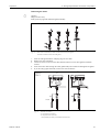
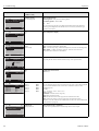
4.3.2
1.
2.
3.
4.
5.
6.
7.
8.
9.
Topclean S
CPA471 / 472 / 475 assemblies
with pneumatic limit position
switches
Screw the multihose onto the bayonet lock, ensuring
it is strain relieved and free of kinks.
Connect hose no. 5 for the position feedback
"Measure" from the Topclean multihose to connection
2 (= output) of the assembly’s lower limit position
switch, see fig. 30.
Connect hose no. 2 for position "Measure" via a Tpiece from the multihose to the upper elbow plug and
to connection 1 (= input) of the assembly’s lower
limit position switch.
Connect hose no. 6 for position feedback "Service"
from the multihose to connection 2 (= output) of the
assembly’s upper limit position switch.
Connect hose no. 3 for position "Service" via a
T-piece from the multihose to the lower elbow plug
and to connection 1 (= input) of the assembly's upper
limit position switch.
Connect the motive water line (D) via a pipe
disconnector (E) to the G3/8 connection of CYR10.
Connect the line for conveyance of cleaning agent (C)
to the G¼ connection of CYR10.
Connect the line from CYR10 to the assembly as
follows:
– If you are not using the CPR40 rinse block (A),
connect the line to the rinse water inlet of the
assembly.
– If you are a using the CPR40 rinse block (A),
connect the line to the "T" connection of CPR40.
If you are using an external valve, connect the line for
steam, additional cleaning agents or sealing water (B)
to the other connection of CPR40.
!Note!
The maximum hose length is 10 m / 32.81 ft:
• Maximum discharge height: 5 m / 16.41 ft
• Max. horizontal discharge width: 10 m / 32.81 ft
• Pressure resistance of internal components:
up to 7 bar / 101.5 psi
• Maximum suction height of buffer/cleaning agent:
2 m / 6.56 ft
C07-CPC300xx-04-12-00-xx-024.eps
ƒig. 29:
A
B
C
D
E
F
Connection of CPA471 / 472 / 475 assemblies with pneumatic limit position
switches
CPR40 rinse block, required for Topclean versions with external valve control for
conveyance of hot, aggressive or pressurised media
Pressurised steam, water, cleaning agent
Cleaner
Motive water 2 ... 7 bar / 29 ... 101.5 psi
Pipe disconnector (customer supplied)
CYR10
C07-CPC300xx-04-012-00-xx-027.eps
ƒig. 30:
Pneumatic limit position switch
1
Input
2
Output
34
Endress+Hauser
Topclean S
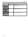
4.3.3
1.
2.
3.
4.
5.
6.
7.
8.
4 Wiring and pneumatic connection of Topclean S
CPA471 / 472 / 475 assemblies
with inductive limit position
switches
Screw the multihose onto the bayonet lock, ensuring
it is strain relieved and free of kinks.
Fold hoses no. 5 and 6 back into the multihose.
Connect hose no. 2 for position "Measure" from the
multihose to the upper elbow plug of the assembly.
Connect hose no. 3 for the position "Service" from
the multihose to the lower elbow plug of the assembly.
Connect the motive water line (D) via a pipe
disconnector (E) to the G3/8 connection of CYR10.
Connect the line for conveyance of cleaning agent (C)
to the G¼ connection of CYR10.
Connect the line from CYR10 to the assembly as
follows:
– If you are not using the CPR40 rinse block (A),
connect the line to the rinse water inlet of the
assembly.
– If you are a using the CPR40 rinse block (A),
connect the line to the "T" connection of CPR40.
If you are using an external valve, connect the line for
steam, additional cleaning agents or sealing water (B)
to the other connection of CPR40.
!Note!
The maximum hose length is 10 m / 32.81 ft:
• Maximum discharge height: 5 m / 16.41 ft
• Max. horizontal discharge width: 10 m / 32.81 ft
• Pressure resistance of internal components:
up to 7 bar / 101.5 psi
• Maximum suction height of buffer/cleaning agent:
2 m / 6.56 ft
C07-CPC300xx-04-12-00-xx-025.eps
ƒig. 31:
A
B
C
D
E
F
Endress+Hauser
Connection of CPA471 / 472 / 475 assemblies with inductive limit position
switches
CPR40 rinse block, required for Topclean versions with external valve control for
conveyance of hot, aggressive or pressurised media
Pressurised steam, water, cleaning agent
Cleaner
Motive water 2 ... 7 bar / 29 ... 101.5 psi
Pipe disconnector (customer supplied)
CYR10
35
4 Wiring and pneumatic connection of Topclean S
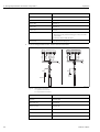
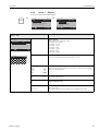
4.3.4
Topclean S
CPA473 / 474 assemblies
with pneumatic limit
switches
The assembly is delivered completely hosed up. All
you have to do is connect compressed air for
pneumatic operation of the ball valve and outputs
for pneumatic feedback signals to the pneumatic
terminal block.
1.
Screw the multihose onto the bayonet lock,
ensuring it is strain relieved and free of kinks.
2. Connect hose no. 5 for position feedback
"Measure" from the multihose to output "5" of
the assembly’s pneumatic connection block.
3. Connect hose no. 2 for position "Measure"
from the multihose to input "2" of the
assembly’s pneumatic connection block.
4. Connect hose no. 6 for position feedback
"Service" from the multihose to output "6" of
the assembly’s pneumatic connection block.
5. Connect hose no. 3 for position "Service" from
the multihose to input "3" of the assembly’s
pneumatic connection block.
6. Connect the motive water line (D) via a pipe
disconnector (E) to the G3/8 connection of
CYR10.
7. Connect the line for conveyance of cleaning
agent (C) to the G¼ connection of CYR10.
8. Connect the line from CYR10 to the assembly
as follows:
– If you are not using the CPR40 rinse block
(A), connect the line to the rinse water inlet
of the assembly.
– If you are a using the CPR40 rinse block (A),
connect the line to the "T" connection of
CPR40.
9. If you are using an external valve, connect the
line for steam, additional cleaning agents or
sealing water (B) to the other connection of
C07-CPC30xxx-12-04-00-xx-026.eps
CPR40.
ƒig. 32:
Connection of CPA473 / 474 assemblies with pneumatic limit position switches
10. If you are using a pneumatic outlet safety
seal (G):
A CPR40 rinse block, required for Topclean versions with external valve control for
– Cut the compressed air hose from the
conveyance of hot, aggressive or pressurised media
connection block input "6" to the
B Pressurised steam, water, cleaning agent
corresponding limit position switch on the
C Cleaner
ball valve drive.
D Motive water 2 ... 7 bar / 29 ... 101.5 psi
– Connect each end of the cut hose to the
E Pipe disconnector (customer supplied)
F CYR10
supplied Y-piece.
– Connect the third connection of the Y-piece G Outlet safety seal (optional)
to the compressed air connection of the
!Note!
outlet safety seal.
The maximum hose length is 10 m / 32.81 ft:
• Maximum discharge height: 5 m / 16.41 ft
• Max. horizontal discharge width: 10 m / 32.81 ft
• Pressure resistance of internal components: up to 7 bar / 101.5 psi
• Maximum suction height of buffer/cleaning agent: 2 m / 6.56 ft
36
Endress+Hauser
Topclean S
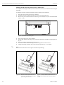
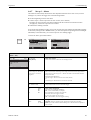
4.3.5
4 Wiring and pneumatic connection of Topclean S
CPA473 / 474 assemblies
with inductive limit switches
The assembly is delivered completely hosed up. All
you have to do is connect compressed air for
pneumatic operation of the ball valve to the
pneumatic terminal block.
1.
2.
3.
4.
5.
6.
7.
8.
9.
Screw the multihose onto the bayonet lock,
ensuring it is strain relieved and free of kinks.
Fold hoses no. 5 and 6 back into the multihose.
Connect hose no. 2 for position "Measure"
from the multihose to input "2" of the
assembly’s pneumatic connection block.
Connect hose no. 3 for position "Service" from
the multihose to input "3" of the assembly’s
pneumatic connection block.
Connect the motive water line (D) via a pipe
disconnector (E) to the G3/8 connection of
CYR10.
Connect the line for conveyance of cleaning
agent (C) to the G¼ connection of CYR10.
Connect the line from CYR10 to the assembly
as follows:
– If you are not using the CPR40 rinse block
(A), connect the line to the rinse water inlet
of the assembly.
– If you are a using the CPR40 rinse block (A),
connect the line to the "T" connection of
CPR40.
If you are using an external valve, connect the
line for steam, additional cleaning agents or
sealing water (B) to the other connection of
CPR40.
If you are using a pneumatic outlet safety
seal (G):
– Connect the connection 2 (= outlet) of the
limit position switch on the ball valve drive
to input "6" of the assembly’s pneumatic
connection block.
– Connect output "6" of the assembly’s pneumatic connection block to the compressed
hose connection of the outlet safety seal.
!Note!
The maximum hose length is 10 m / 32.81 ft:
• Maximum discharge height: 5 m / 16.41 ft
• Max. horizontal discharge width: 10 m / 32.81 ft
• Pressure resistance of internal components:
up to 7 bar / 101.5 psi
• Maximum suction height of buffer/cleaning
agent: 2 m / 6.56 ft
Endress+Hauser
C07-CPC30xxx-12-04-00-xx-019.eps
ƒig. 33:
A
B
C
D
E
F
G
Connection of CPA473 / 474 assemblies with inductive limit position switches
CPR40 rinse block, required for Topclean versions with external valve control for conveyance of hot, aggressive or pressurised media
Pressurised steam, water, cleaning agent
Cleaner
Motive water 2 ... 7 bar / 29 ... 101.5 psi
Pipe disconnector (customer supplied)
CYR10
Outlet safety seal (optional)
37
4 Wiring and pneumatic connection of Topclean S
4.4
Topclean S
Connection diagram Non-Ex
C07-CPC300xx-04-12-00-en-001.eps
ƒig. 34:
!
38
Electrical connection for Topclean S in the non-Ex area
Note!
Size proportions are not considered.
Endress+Hauser
Topclean S
4 Wiring and pneumatic connection of Topclean S
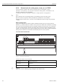
4.5
Connection compartment sticker CPG30
C07-CPC30xxx-18-12-00-xx-001.eps
ƒig. 35:
Connection compartment stickers for CPG30, 24 VAC/DC
* With Ex versions, the LED lights when the assembly is in service position.
C07-CPC30xxx-18-12-00-xx-002.eps
ƒig. 36:
Connection compartment stickers for CPG30, 100 / 110 / 230 VAC/DC
* With Ex versions, the LED lights when the assembly is in service position.
Endress+Hauser
39
E2: CC "Clean"
E3: CC "User"
E1: ext.Hold
15V 9mA
CPC Supply
I1: 0-20mA / Hart
CPC RS485
I2: 0-20mA
PH
NC 97 96 88 87 S
NC 97 96 88 87 S
weiß / white
braun / brown
88
87
gelb / yellow
weiß / white
12
13
Schirm auf PE / screen to PE
PA
grün / green
96
grün / green
11
13
12
11
REF
SRC
weiß / white
(gelb / yellow)
grün / green
braun / brown
Koax / coax
rot / red
Kanal / channel 1
DRN
F
L
N
Pt1000
Kanal / channel 2
DRN SRC REF PA 12 13 11 S
ISFET
DRN SRC REF PA 12 13 11 S
gelb / yellow
Kanal / channel 2
NC NC
Digitaler Sensor /
digital sensor
Kanal / channel 1
NC NC
Alarm contact
97
Pt100 / Pt1000
Kanal / channel 2
REF PA 12 13 11 S
Relay contact 1
braun / brown
Koax / coax
PH
Relay contact 2
PA
REF
pH / mV
Kanal / channel 1
REF PA 12 13 11 S
Glaselektrode / glass electrode
zusammengehörige
Klemmen /
combined clamps
F
52 55 45
Relay contact 4
Relay contact 5
Relay contact 3
52 55 22
-
51 54 21
Relay contact 3
4 - 20 mA
51 54 44
Relay contact 4
+
52 55 22
-
51 54 21
-..3..
0 - 1kW/10kW
+
Relay contact 3
-..2..
Klemmen (Rückseite) /
terminals (back side)
Verbindungsleitung /
connecting line
3. Verbindungsleitung zwischen Rückseite Klemme und
Transmittermodul entfernen. /
Remove the line connecting the terminal back side and
the transmitter module.
Transmittermodul /
transmitter module
2. Gehäuse-Oberteil des CPM 153 öffnen. /
Open the housing cover of the CPM 153.
1. Gehäuse-Unterteil des CPM153 öffnen und Leitungen des
Sensorkabels von Klemmen am Gehäusedeckel abziehen. /
Open the lower housing section of the CPM153 and remove the
wires of the sensor cable from the terminals in the housing cover.
+
52 24 22
- -
51 23 21
+
-..4..
52 24 22
- -
6. Sensorkabel entsprechend ISFET-Belegung anschließen. /
Connect sensor cable according to ISFET assignment.
5. Gehäuse-Oberteil des CPM 153 wieder schließen. /
Close the housing cover of the CPM 153.
Klemmen (Rückseite) /
terminals (back side)
Steckbrücken /
jumpers
4. Steckbrücken entsprechend der Zeichnung hinten an den Klemmen
aufstecken. /
Plug the jumpers onto the back side of the terminals as shown below.
Transmittermodul /
transmitter module
+
51 23 21
+
-..5..
Kontakte, Best.-Variante / contacts, order code.
4 - 20 mA
-..1..
Relay contact 4
Wechsel Glas auf ISFET / Changing from glass to ISFET
non EX
Relay contact 3
EX
4 - 20 mA
CPM153
Stromausgang / current out / Hart
4 - 20 mA
40
0 - 1kW/10kW
4.6
Relay contact 3
135042-0001-4C
4 Wiring and pneumatic connection of Topclean S
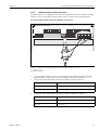
Topclean S
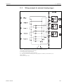
Connection compartment sticker Mycom
ƒig. 37:
Connection compartment sticker (in the connection compartment of the transmitter)
DRN = Drain
SCR = Source
REF = Reference
C07-CPM153xx-04-06-00-xx-012.eps
Endress+Hauser
Topclean S
4 Wiring and pneumatic connection of Topclean S
4.7
Post connection check
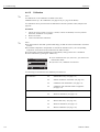
Instrument status and specifications
Remarks
Is the measuring instrument or the cable damaged externally?
Visual inspection
Electrical connection
Remarks
Does the supply voltage match the specifications on the nameplate?
CPM153:
100 V ... 230 V AC long-range
24 V AC / DC
CPG30:
100/110/230 V AC recodeable
24 V AC / DC
Do the cables used fulfil the required specifications?
Use an original E+H cable for
electrode and sensor connection, see
"Accessories".
Are the installed cables strain-relieved?
Is the cable type route completely isolated?
Along the whole cable length, run
the power supply and signal line
cables separately to avoid any mutual
influence. Cable channels are best.
No loops and cross-overs in the cable run?
Are the power supply and signal cable correctly connected?
Are all the screw terminals properly tightened?
For connection with potential matching (PML):
Is the PML connected to the measuring medium or the buffer solution?
!
Note!
During calibration, insert the PML
into the buffer solution.
For connection without potential matching (PML):
Is the potential matching line grounded?
Endress+Hauser
Are all the cable entries installed, tightened and sealed?
Cable run with "water sag"?
"Water sag": cable circuit hanging
down so that water can drip off.
Are all the housing covers installed and tightened?
Check seals for damage.
Is the multihose placed sheltered?
Use protection pipe if necessary.
41
5 Operation
Topclean S
5
Operation
5.1
Display and operating elements
5.1.1
Display reading/symbols
8
1
Measure
2
3
HOLD
7.54
pH
Select [¯ ]
11
MEAS
CAL
DIAG
PARAM
6
7
10
Failure
4
5
9
12
13
?
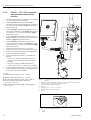
C07-CPM153xx-19-06-00-en-002.eps
Mycom S CPM153 user interface
1: Current menu; hand symbol: sign for manual operation
2: Current parameter
3: Navigation bar: Arrow keys for scrolling, "E" for browsing, note for Cancel
4: "MEAS" (Operation) key
5: "CAL" (Calibration) key
6: "DIAG" (Diagnosis menu) key
7: "PARAM" (Parameter entry menu) key
? = Press DIAG and PARAM simultaneously to open the help pages
8: HOLD display, if HOLD active; OFFSET, if an offset has been edited in pH or redox mode
9: Current main measured value
10: "Failure" display, "Warning", if the NAMUR contacts respond
11: Labelling strip
12: Arrow keys for scrolling and editing
13: ENTER key
5.1.2
Key assignment
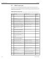
"PARAM" brings you to the Configuration menu of the Topclean S CPC30.
PARAM
!
Note!
PARAM" allows you to return to the previous "return field" from any point in the menu. These are
marked in bold in the menu overview (s. chap. 11.1).
LED: This is the send LED for the service adapter "Optoscope" (see "Accessories").
"DIAG" brings you to the instrument diagnosis menu.
LED: This is the receive LED for the service adapter "Optoscope" (see "Accessories").
Help:
Press the "DIAG" and "PARAM" keys simultaneously to open the help page.
42
Endress+Hauser
Topclean S
5 Operation
"MEAS" switches to Operation. This displays the measured values. Use the arrow keys to scroll
through the different measuring menus.
!
Note!
Press "MEAS" to exit any of the "PARAM", "DIAG", "CAL" menus without terminating the settings
/ calibration.
"CAL" switches to the calibration menu of the electrodes.
"E" (Enter) moves you one step forward in a menu or confirms a selection you made.
LED (status display):
green: everything OK.
red: an error has occurred.
• You can scroll through the menu options with the arrow keys, and then highlight your selection
(if there is a choice offered)
or
• Increment or decrement numbers by one step with "+" / "-".
Move to the next digit with the "right arrow" (editor type 1) or
• "Activate" with the "right arrow" and scroll through the selection with "+" / "-"
(editor type 2) (for information on editor types, see page 46).
5.1.3
Operation of the service switch
The service switch is located on the door of the CPG30 housing. There are two possible switch
positions:
Service / Off:
(horizontal switch setting)
• The electrode moves into the rinse chamber.
• "Hold" is active for the outputs.
Measure / On:
(vertical switch setting)
After moving from the service position, a query appears asking whether a
programme should be launched or the electrode should be moved into the
process without cleaning.
Only those programmes are offered which have already been edited.
!
Endress+Hauser
Note!
The service switch always has priority (Emergency shutdown). This means that any running
programme is interrupted as soon as you operate the service switch.
43
5 Operation
Topclean S
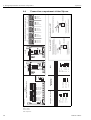
5.1.4
Measuring menus
You can choose between different measuring menus. Use the arrow keys to scroll between the different menus. Switch between the measured value characteristic and the data log using the ENTER
key F.
pH
Measure
W
V
Measure
7.54
2.00
The current measured value is displayed.
W
V
If you have activated the data log, you can
see the current measured value
characteristic here (record mode).
If you have activated both data logs, press
the arrow key to switch to the view of the
second measured value characteristic.
Measure
Output 1
Output 2
Rel. A 1 2 3 4 5
12.00
Select [¯ ]
Select
pH 7.00
pH 7.54
pH1
0 mV
-32 mV
10.00 mA
0.00 mA
Measure
W
V
pH 7.54
0 mV
Auto
Clean
Ext.
off
off
off
-----------------Clean C runs
Wat er
10s
Assembly
Service
Select [¯ ]
Measure
pH
ATC
Temperature
Select [ ¯]
7.54
25.0 °C
W
V
In this display you can see the measured
value, the kind of temperature
compensation and the related
temperature.
W
V
Select [ ¯]
In this measuring menu, you can see the
current and voltage values and the
contact states of the relay at a glance.
Active relay = ■ (with function)
Inactive relay = In this display you can see the measuring
value, the status of automatic, cleaning
and external control as well as the the
status of a running cleaning programme.
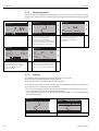
5.1.5
Data log
The CPM153 offers two data logs. With these data logs, you can record
• one parameter with 500 sequential measuring points
• two parameters each with 500 sequential measuring points.
To be able to use the function, activate the data log in the "PARAM" menu ➠ "Set up 2" ➠ "Data
log" (see page 72). The function is active immediately.
You can view the measured values by scrolling through the different measuring menus (see above).
– The current measured values are recorded in Record mode.
– In the "PARAM" menu ➠ "Set up 2" ➠ "Data log" ➠ "DataLog display 1/2" you can display saved
data with date and time.
Measure
2.00
pH1
12.00
pH 7.54
Para
DataLog View 1
7.54 pH
44
Select [¯ ]
12:15:35
Record mode
Scroll mode
09.04.04
Endress+Hauser
Topclean S
5 Operation
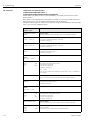
5.1.6
Operation access authorisation
To protect the transmitter against an unintended or undesired change in the configuration and
calibration data, functions can be protected using four-digit access codes.
Access authorisation has the following levels:
Read-only level (accessible without a code):
The complete menu can be viewed. The configuration cannot be altered. No calibration is possible.
Service code
Operator level (can be protected by the service code):
This code permits calibration.
Use this code to operate the temperature compensation item. The test functions and the internal
data can be viewed.
Factory setting Code = 0000, i.e. the levels are not protected.
In case you have mislaid/forgotten the entered maintenance code, contact your Endress+Hauser
service for a universally valid maintenance code.
Specialist code
Specialist level (can be protected by the specialist code):
All menus can be accessed and changed.
Factory setting Code = 0000, i.e. the levels are not protected.
In case you have mislaid/forgotten the entered specialist code, contact your Endress+Hauser service
for a universally valid specialist code.
To activate the codes (= functions locked) see the item "PARAM"➠ "Set up 1" ➠ "Access codes"
(see page 58). Enter your desired code here. If the code is activated, you can only edit the protected
areas with the rights mentioned above.
!
Note!
• Note down the selected code as well as the universal code and keep it in a place where
unauthorised persons do not have access to it.
• If you reset the code to "0000", all levels are freely accessible for editing. The code can only be
reset on the specialist level.
Locking the operation
Pressing Ï and Ð simultaneously locks the in-field operation of the
instrument.
At the code prompt, the code appears as "9999".
Unlocking the operation
Press Ò and Ñ simultaneously to unlock the operation.
Endress+Hauser
45
5 Operation
Topclean S
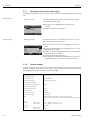
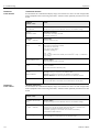
5.1.7
Description of the menu editor types
At parameter setting, the functions can be selected in two different modes, depending on the setting
type.
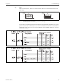
Editor type E1
Editor type 1 (E1)
for functions which can be directly selected from the display.
The editing row shows "Edit".
pH 7.00
Hold
Param
Sensor input
pH
Redox/ORP mV
Redox/ORP %
Edit
Editor type E2
[¯ ]
Next [E]
Editor type 2 (E2)
pH 7.00
Param
Weekday
Day
Month
Year
Time
Select
5.1.8
• A selection can be highlighted with the arrow keys
V and W.
• Confirm the selection by pressing F.
for settings which have to be defined more precisely, e.g. day,
time. The editing row shows "Select".
Hold
Date+time
Mo
30
04
01
12 00
Next E
• Use the arrow keys V and W to highlight a selection (e.g.
"Mo").
• Activate the selected option with the right arrow key T. The
highlighted option flashes.
• "Toggle": i.e. scroll through the selection (e.g. the weekdays)
with the arrow keys V and W.
• Confirm the selection by pressing F.
• After making your selection and confirming it by pressing F
(no flashing display), you can exit the item by pressing F.
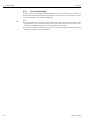
Factory settings
All factory settings are active when the instrument is switched on for the first time. The table below
lists all main settings. For all further factory settings, refer to the description of the function groups
(from page 56), there the factory setting is printed in bold).
Parameter
One-circuit instrument
Select operating mode
pH
Select electrode type
Glass electrode 7.0
Select connection type
Solution ground (with PML)
Select temperature display
°C
Select temperature compensation
ATC K1
Temperature measurement
off
Select temperature sensor
Pt 100
Contact functions
NAMUR
Select current output 1
pH/Redox K1
Select current output 2
Temperature K1
Hold
PARAM, CAL: Active after entry of service or specialist code
DIAG: active after entry of service or specialist code for functions that require
a code.
Current
output 1:
Current
output 2:
46
0/4 mA value:
20 mA value:
pH 2 / –1500 mV / 0.0% / 0.0 °C
pH 12 / +1500 mV / 100.0% / 100.0 °C
0/4 mA value:
20 mA value:
Temperature
0.0 °C
100.0 °C
Endress+Hauser
Topclean S
5 Operation
5.2
Replaceable memory
The DAT module is a memory device (EEPROM) which is plugged into the connection
compartment of the transmitter. Using the DAT module you can
• save the complete settings, the logbooks and the data log of a transmitter and
• copy the complete settings to other CPM153 transmitters with identical hardware functionality.
This considerably reduces the effort to install or service several measuring points.
Endress+Hauser
47
6 Commissioning
Topclean S
!
6
Commissioning
6.1
Special features for measurement with digital sensors
with Memosens technology
Note!
Digital sensors with Memosens technology can only be used in combination with the appropriate
Topclean S version (CPC30-xx5xxxxxxx).
You can retrofit an existing Topclean S for Memosens technology (see page 134).
Commissioning
Digital sensors with Memosens technology save calibration data. Therefore, commissioning of these
sensors differs from the commissioning of standard electrodes. Proceed as follows:
1.
2.
3.
4.
5.
6.
Install the transmitter and the assembly.
Connect the transmitter and the sensor cable.
Configure the transmitter according to your specific requirements (see »Description of
functions« on page 56).
Connect the factory-calibrated sensor with Memosens technology and immerse it in the
medium or buffer.
The saved sensor-specific calibration data are automatically transferred to the transmitter.
The measured value is displayed.
Data storage
Digital sensors are able to store the following data:
• Manufacturing data
– Serial number
– Order code
– Date of manufacture
• Calibration data
– Calibration date
– Calibrated slope at 25 °C / 77 °F
– Calibrated zero point at 25 °C / 77 °F
– Temperature offset
– Serial number of the transmitter used for the last sensor calibration
– Buffer values of the last calibration
– Change in slope compared to preceding calibration
– Change in zero point compared to preceding calibration
• Application data
– Temperature application range
– pH application range
– Operating hours at temperatures above 80 °C / 176 °F and 100 °C / 212 °F
– Operating hours at very low and very high pH values (Nernst voltage below -300 mV,
above +300 mV)
– Number of sterilisations
To display these sensor data, select Ð ➠ Ext. sensor data.
48
Endress+Hauser
Topclean S
6 Commissioning
6.2
Special features for measurement with ISFET sensors
Switch-on behaviour
A closed control loop is created once the measuring system is switched on. During this time (approx.
5-8 minutes), the measured value adjusts to the real value. This settling behaviour occurs each time
the liquid film between the pH-sensitive semiconductor and the reference lead is interrupted (e.g.
caused by dry storage or intensive cleaning with compressed air). The settling time in question
depends on how long the interruption lasts.
Sensitivity to light
Like all semiconductor elements, the ISFET chip is sensitive to light (measured value fluctuations).
However only intense direct illumination impinges on the measured value. For this reason, avoid
direct exposure to sunlight during calibration. Normal ambient light does not affect measurement.
6.3
#
"
Installation and function check control
Warning!
Before power-up, make sure there is no danger to the measuring point. Uncontrolled actuated
pumps, valves or similar could lead to damage to instruments.
Caution!
• Before switching on, check all the connections again for correctness.
• Make sure that the pH or redox electrode and the temperature sensor are in the medium or in a
buffer solution, otherwise no plausible measured value can be displayed.
• Make also sure that the connection check has been carried out (s. chap. 4.7).
6.4
Switching on the device
Before first start-up, make sure you understand how to operate the device. You should make
particular reference to Chapters 1 ("Safety instructions") and 6 ("Operation").
We recommend the following procedure for commissioning:
1.
2.
3.
4.
5.
6.
7.
8.
Endress+Hauser
Connect Mycom S CPM153 to the power supply.
Switch the service switch to "OFF" or to the Service position
.
Wait for initialisation of CPM153 and CPG30.
Function of the green "Alive LED":
– Frequency 2/sec: communication is running
– Frequency 1/sec: communication is loading
– LED lights up constantly: no communication
If the LED does not light up, check the power supply at terminals L+/L– (setpoint: 12 volts).
First commissioning only:
Execute the menu "First start up", chap. 6.5, page 51.
Switch the service switch to the Measuring position
or to "ON".
Set the following parameters:
– Select a function for the additional valve (page 93).
– Configure the times of the "Clean" programme (page 54).
Start the "Clean" programme and check the entire system for leaks.
Programme start:
"PARAM" ➠ Specialist ➠ Manual operation ➠ Topclean ➠ Status messages (Enter) ➠ "Start
programme" ➠ "Clean"
Now configure the complete system via the menu.
49
6 Commissioning
Topclean S
6.4.1
First commissioning
On first switch-on, the instrument starts automatically with the First start up menu. This asks you
about the most important instrument settings. After you close the menu, the instrument is ready for
use and measurement in its standard configuration.
!
50
Note!
• You must completely run through the First start up menu. If you do not, the instrument will not
be operational. If you interrupt First start up, it will start again the next time you switch on the
instrument until all menu options have been processed and completed.
• If you have activated the specialist code, you have to enter it for all parameter settings. By default
(0000), the specialist code is not requested.
Endress+Hauser
Topclean S
6 Commissioning
6.5
First start up
In the First start up menu, configure the most important transmitter functions. The First start up ist
started automatically when starting the instrument for the first time. You can open the First start up
at any time from the menu structure.
To enter the menu, proceed as follows:
⇒
PARAM
Hold
pH 7.00
Operating level
Param
Read only
Operator
Specialist
⇒
Hold
pH 7.00
Operating level
Param
Spec. access code
0 000
⇒
Hold
pH 7.00
Settings
Param
Set up 1
Set up 2
Manual operation
First start up
Edit
Display
pH 7.00
Param
English
Deutsch
Edit
Hold
Language
Hold
Contrast
Edit +-
Next E
pH 7.00
Param
Weekday
Day
Month
Year
Time
Select
Hold
Date+time
pH 7.00
Hold
Mo
30
04
01
12 00
Next E
Param
Sensor input
pH
Redox/ORP mV
Redox/ORP %
Edit
[¯ ]
Endress+Hauser
E
D
Select language
Depending on ordered language version:
Language version variants:
-A: English / German
-B: English / French
-C: English / Italian
-D: English / Spanish
-E: English / Dutch
-F: English / Japanese
Next E
Edit
Next E
Contrast setting as necessary
You can increase and reduce the contrast with the +/- keys.
Mo
01
04
01
12:00
Date and time entry
Enter the complete date and time here.
pH
Redox mV
Redox %
Operating mode selection
Glass el. 7.0
Glass el.4.6
Antimony
ISFET
Select electrode type
(only pH)
Next [E]
pH 7.00
Hold
Param pH electr.typeK1
Glass El. 7.0
Glass El. 4.6
Antimon
IsFET
Edit
INFO
E
pH 7.00
Param
Next E
CHOICE
(default = bold)
GB
D
Next
Next E
0...9997
Edit
!
Note!
• If the operating mode changes, all the user settings are automatically reset!
• For digital sensors with Memosens technology, only the pH operating mode is
available.
• Here it is sensible to use the DAT module to save your settings.
!
Note!
• In the event of a change from glass or antimony electrode to ISFET, the temperature
sensor is reset to Pt 1000 as a default. Conversely, Pt 100 is selected.
• The Topclean S version glass / ISFET (CPC30-xx2xxxxxxx) is factory set for
measurement with glass electrodes.
• For digital sensors with Memosens technology, only the electrode type Glass el. 7.0
is available.
51
6 Commissioning
Topclean S
Display
pH 7.00
Hold
Sensor ground
Param
solution ground
no solution ground
CHOICE
(default = bold)
INFO
solution ground
no solution ground
Select connection type
solution ground = with potential matching (PML)
no solution ground = without PML
!
Note!
The connection type selection is not displayed for digital sensors with Memosens
technology. With digital data transmission there is no need for symmetrical highimpedance connections.
E
Edit
pH 7.00
Hold
Temp. unit
Param
°C
°F
°C
°F
Select temperature display
ATC
MTC
MTC+Temp
Select temperature compensation
ATC = automatic temperature compensation
MTC = manual temp. comp. (with fixed temperature, entered in the following field)
MTC+Temp. = as MTC. The display, however, shows the value which the
temperature sensor measures in the medium.
025.0 °C
Temperature value
(only with pH and selection of MTC or MTC+Temp. in the previous field)
off
on
Temperature measurement
(Redox only)
E
Edit
pH 7.00
Param
ATC C1
MTC
MTC+Temp
Edit
Temp.comp. 1
Next
pH 7.00
E
Hold
MTC-Temp. C1
Param
025.0°C
-20.0... 150.0°C
Edit
Next[E]
[¯ ®]
mV - 114
Param
off
on
Hold
Temp.meas1
Next E
Edit
pH 7.00
Hold
Relay funct.
Param
Acc.Namur
off
Relay 1
N/C
Relay 2
N/C
Relay 3
N/C
¯Relay 4
N/C
Select [¯ ®]
Next[E]
pH 7.00
Hold
Output 1
Param
pH/mV Input 1
Temperature Input1
Edit
52
[¯]
NAMUR
Relay 1
Relay 2
Relay 3
Relay 4
Relay 5
pH/mV K1
Temperature K1
off
N/C
N/C
N/C
N/C
N/C
Contact functions
You can assign the function of up to 5 relays here. The relays 1 and 2 will be assigned
to an activated NAMUR function and will not be available for other functions
(compare page 27).
Selection:
N/C / Controller / Limit / CCW / CCC
N/C: no function
Controller: Controller control using relay
Limit: Limit contactor function
CCW: Chemoclean water. Water supply for the Chemoclean function.
CCC: Chemoclean Cleaner. Cleaner supply for the Chemoclean function.
(Together, CCC and CCW form the "Chemoclean" function. You can find information
on Chemoclean on page 98).
Select current output 1 parameter
Selection of the parameter which shall be output on the current output.
Next[E]
Endress+Hauser
Topclean S
6 Commissioning
Display
pH 7.00
Hold
Output 2
Param
pH/mV Input 1
Temperature Input1
Controller
Edit
[¯]
pH 7.00
Param
0...9, A...z
Edit
[¯ ®]
pH 7.00
Param
restart
end
Edit
Endress+Hauser
CHOICE
(default = bold)
INFO
pH/mV K1
Temperature K1
Controller
Select current output 2 parameter
Selection of the parameter which shall be output at the current output.
Controller: Control of a controlling actuator via the current output (see also
Controller menu page 74).
(0...9; A...Z)
Enter your customer specific instrument number.
32 digit tag number.
This is saved in the DAT module which is obtainable as an option.
end
restart
Exit First start up?
restart = Run through the First start up again.
end = Save the settings and exit First start up.
Next[E]
Hold
Tag number
Next[E]
Hold
Start up
Next E
53
6 Commissioning
Topclean S
6.5.1
Configuring Clean programme (via automatic function)
The following example shows how to configure the cleaning programme Clean for your Topclean.
For a description of all cleaning functions and cleaning programmes, see page 88 ff.
To enter the menu, select:
⇒
PARAM
Hold
pH 7.00
Param
Settings
Set up 1
Set up 2
Manual operation
Display
Hold
pH 7.00
Param
Set up 2
Check systems
Controller settings
Limit switch
Hold
pH 7.00
Topclean
Param
Set up Topclean
Activate Topclean
Contr. quick adj.
Topclean
First start up
Edit
⇒
Next E
Edit
Next E
Next E
Edit
Action
The current status of the cleaning functions is displayed. Press F to
continue.
Select "Automatic" and confirm by pressing F.
Select a day that you want to edit e.g. Monday and press F.
Select "Edit day" and confirm by pressing F.
Press T. The option "no prog." is activated. Press W to select the
"Clean" programme. Press F.
Press V and F to edit Clean.
54
Endress+Hauser
Topclean S
6 Commissioning
Display
Action
Use the arrow keys to select the programme step that you want to edit,
e.g. water. To edit the programme step, press F.
Use the arrow keys to set the required water conveyance interval. Press
F to return to the list of programme steps.
If necessary, edit other programme steps. The overall programme time is
calculated automatically.
When you are finished with the configuration, press
.
PARAM
Press W and T and use the arrow keys to set the start time of Clean,
e.g. 07:00 a.m.. Confirm by pressing F. The end time is calculated
automatically.
!
Note!
To test the automatic function, allow the system a lead time of min. 10
minutes when entering the start time.
When the configuration is finished and you want to start Clean via the
automatic function, you must activate this function. To do so, press
until you reach the first Topclean selection.
Select "Activate Topclean" and confirm by pressing F.
PARAM
Select the status of "Automatic". Press T and W to set Automatic to
"on". Confirm by pressing F.
The automatic function is now activated. The selected cleaning
programmes will be started on the selected weekday at the set time
based on the time and date entered in "Setup 1 ➠ Display" (see page 57).
Press
Endress+Hauser
to return to operation.
55
6 Commissioning
Topclean S
6.6
Description of functions
6.6.1
Set up 1 – Sensor input
In this menu, you can change the measured value acquisition settings, such asthe operating mode,
the measuring principle or the electrode type.
Apart from the signal attenuation, you have already made all menu settings at the first
commissioning in First start up (see page 51). You can change the selected values in this menu.
To access the parameter setting menu, you have to enter your specialist code (see page 45, page 58).
Proceed as follows:
⇒
PARAM
Hold
pH 7.00
Operating level
Param
Read only
Operator
Specialist
⇒
Hold
pH 7.00
Param
Set up 1
Sensor input
Display
Access codes
Current output
Relays
Edit
Next E
CHOICE
(default = bold)
pH 7.00
[¯ ]
Next E
INFO
Hold
Param
Sensor input
pH
Redox/ORP mV
Redox/ORP %
Edit
Edit
pH
Redox mV
Redox %
Operating mode selection
If the operating mode changes, the user settings are automatically reset.
Next [E]
Glass el.
Glass el.
Antimony
ISFET
7.0
4.6
Select electrode type 1
(pH only)
!
Note!
• When changing from glass or antimony electrode to ISFET, the temperature sensor is
reset to Pt 1000 as a default. Conversely, Pt 100 is selected.
• The Topclean S version glass / ISFET (CPC30-xx2xxxxxxx) is factory set for
measurement with glass electrodes.
• For digital sensors with Memosens technology, only the electrode type Glass el. 7.0 is
available.
solution ground
no solution
ground
Select connection type
solution ground = with potential matching (PML)
no solution ground = without PML
!
Note!
For further information, see page 20.
pH/redox:
Temperature:
00 s
00 s
Set measured value attenuation
The mean value over the set time is displayed. There is no attenuation for the 00s value.
(00...30s)
56
Endress+Hauser
Topclean S
6 Commissioning
6.6.2
Set up 1 – Display
To enter the menu, proceed as follows:
⇒
PARAM
Hold
pH 7.00
Param
Parametrieren
Settings
Set up 1
Grundeinstellung
Set
up 2
Sonderfunktionen
Manual operation
Handbedienung
Quick start
First
Setup up
Edit
pH 7.00
Param
English
Deutsch
Edit
pH 7.00
Param
Current output
Relays
Next E
INFO
Hold
Language
E
D
Select language
Depending on ordered language version:
Language version variants:
-A: English / German
-B: English / French
-C: English / Italian
-D: English / Spanish
-E: English / Dutch
-F: English / Japanese
GB
D
Next
E
Contrast setting as necessary
You can increase and reduce the contrast with the +/- keys.
H
Cont
Weekday:
Day:
Month:
Year:
Time:
Su
01
04
01
08:00
Date and time entry
Enter the complete date and time here. These data are used as basis for all log books
and the cleaning programmes.
pH
pH
00.00
00.0
Select no. of decimal places
(only for pH measuring type)
°C
°F
Select temperature unit
00000000
Enter your customer specific instrument number.
32 digit tag number.
The number is saved in the DAT module which is obtainable as an option.
(0...9; A...Z)
Endress+Hauser
Hold
pH 7.00
Param
Set up 1
Sensor input
Display
Access codes
Edit
Weiter
Next E
CHOICE
(default = bold)
⇒
57
6 Commissioning
Topclean S
6.6.3
Set up 1 – Access codes
To enter the menu, proceed as follows:
⇒
PARAM
Hold
pH 7.00
Param
Parametrieren
Settings
Set up 1
Grundeinstellung
Set
up 2
Sonderfunktionen
Manual operation
Handbedienung
Quick start
First
Setup up
Edit
CHOICE
(default = bold)
pH 7.00
Param
⇒
Hold
pH 7.00
Param
Set up 1
Sensor input
Display
Access codes
Current output
Relays
Edit
Weiter
Next E
Next E
INFO
Hold
0000
Service Code
(0 ... 9997)
Enter service code
In the range 0000 ... 9997, the code can be freely selected.
0000 = no security locking.
0 000
0...9997
Edit
Next E
0000
(0 ... 9997)
!
58
Enter specialist code
In the range 0000 ... 9997, the code can be freely selected.
0000 = no security locking.
Note!
Danger of misuse.
Make sure that the codes you enter and the universal code (see page 45) are protected against
misuse by unauthorised persons. Note down the codes and keep them in a place where
unauthorised persons do not have access.
Endress+Hauser
Topclean S
6 Commissioning
6.6.4
Set up 1 – Current outputs
The transmitter is always equipped with two current outputs.
To enter the menu, proceed as follows:
⇒
PARAM
Hold
pH 7.00
Param
Parametrieren
Settings
Set up 1
Grundeinstellung
Set
up 2
Sonderfunktionen
Manual operation
Handbedienung
Quick start
First
Setup up
Edit
⇒
Weiter
Next E
CHOICE
(default = bold)
Hold
pH 7.00
Param
Set up 1
Sensor input
Display
Access codes
Current output
Relays
Edit
Next E
INFO
Current output 1
Current output 2
Select a current output
for which the settings apply.
pH/Redox
Temperature
Controller (current output 2 only)
Selecting parameters
which should be output at the current output.
Selection possibilities related to the instrument variant and the
selected output.
Current output 1 (terminals 31+, 32-):
– pH/redox
– Temperature
Current output 2 (terminals 33+, 34-):
– pH/redox
– Temperature
– Controller: Control of a controlling actuator via the current
output (see also Controller menu page 74).
Current output 1 (or 2):
pH 7.00
Hold
Output 2
Param
pH/mV Input 1
Temperature Input1
Controller
Edit
[¯]
Next[E]
!
Note!
Danger of data loss. If you change the assignment for the current
output from "controller" to a different function after you have
configured the controllers, the complete controller settings
(see page 74) are reset to the default values.
Caution!
The configuration is changed.
Note in display (for changed setting):
Cancel by pressing "PARAM"
Continue (= confirm change) by pressing "E"
0 ... 20 mA
4 ... 20 mA
Current range selection
!
Note!
If you change the current range after editing the table, the table will
be reset.
Endress+Hauser
!!Caution!!
Current output 0...20 mA and error current =
2.4 mA is dangerous.
Note in display:
Error current lies within the measuring current range. When the
current range is "0 ... 20 mA" and "Min" is selected under Alarm in
(see page 65).
Recommended combinations:
Current range 0...20 mA and error current max (22 mA)
or
Current range 4...20 mA and error current min (2.4 mA)
Linear
Table
Characteristic selection
Linear: The characteristic is linear from the lower to the upper
value.
Table: When you do not want the current output characteristic to
be linear, you can enter a customer-specific sequence of up to 10
value pairs in a table. Exact adaptation to the non-linear medium
behaviour can achieve a higher level of accuracy.
59
6 Commissioning
Topclean S
CHOICE
(default = bold)
INFO
Linear:
pH 7.00
Param
0/4mA :
20mA :
Hold
Output 1
02.00 pH
12.00 pH
0/4 mA: 02.00 pH
/ 000.0 °C / -0500 mV
20 mA: 12.00 pH
/ 100.0 °C / 0500 mV
Entry of the upper and lower measured value limits
The maximum range of the measured value is
–2 ... +16 pH.
The minimum distance from the upper to the lower measured
value limit is 2 pH units.
(Exmp.: 0/4 mA: pH 7 and 20 mA: pH 9)
Linear characteristic active.
Note in display:
The linear characteristic is activated after confirmation by pressing
"E". Cancel by pressing "PARAM".
01
(1 ... 10)
Entry of the number of support points (value pairs)
pH/Redox/°C/: 000.0
mA: 04.00
Value pair entry
pH/Redox/°C - mA (number of required value pairs = number of
support points entered in the previous field).
Next[E]
Select[¯®]
Table:
pH 7.00
Param
Total pairs
Hold
Table 1
01
1... 10
Edit[ ¯®]
Next[E]
Example of value pairs with 4 support points:
C07-CPM153xx-05-06-00-xx-002.eps
ƒig. 38:
60
Example of entering a characteristic using a table
OK
Delete pair(s)
Selection:
Are the value pairs OK or do you want to delete pairs?
pH/Redox/°C/: 000.0
mA: 04.00
Delete:
Select the rows to be deleted, delete them with T and confirm
this with F.
Table valid
Note in display (no entry)
Table status. If invalid, then back to previous field.
Table active
Note in display:
The table is active after confirmation by pressing F. Cancel by
pressing "PARAM".
Endress+Hauser
Topclean S
6 Commissioning
6.6.5
Set up 1 – Relays
To enter the menu, proceed as follows:
⇒
PARAM
Hold
pH 7.00
Param
Parametrieren
Settings
Set up 1
Grundeinstellung
Set
up 2
Sonderfunktionen
Manual operation
Handbedienung
Quick start
First
Setup up
Edit
Hold
pH 7.00
Param
Set up 1
Sensor input
Display
Access codes
Current output
Relays
Edit
Weiter
Next E
CHOICE
(default = bold)
pH 7.00
Hold
Relay funct.
Param
Acc.Namur
off
Relay 1
N/C
Relay 2
N/C
Relay 3
N/C
¯Relay 4
N/C
Select [¯ ®]
Next[E]
⇒
Next E
INFO
NAMUR:
Relay 1:
Relay 2:
Relay 3:
Relay 4:
Relay 5:
off
N/C
N/C
N/C
N/C
N/C
Contact functions
You can assign the function of up to 5 relays here. The relays 1 and 2 will be assigned to an activated NAMUR function and will not be available for other functions
(compare with page 27).
Selection:
N/C / Controller / Limit / CCW / CCC
N/C: no function
Controller: Controller control using relay
Limit: Limit contactor function
CCW: Chemoclean water. Water supply for the Chemoclean function.
CCC: Chemoclean cleaner. Cleaner supply for the Chemoclean function.
(Together, CCC and CCW form the "Chemoclean" function. You can find
information on Chemoclean on page 98 ).
The limit value/controller contacts are configured in the menu "PARAM" ➠ "Set
up 2" ➠ "Controller settings".
!
Note!
• Danger of data loss. If you change the relay allocation after configuring the
controller and the number of relays available to the controller is reduced, the
complete controller settings (see page 74) are reset to the default values.
• If you change the relay assignment for the controller, you must use the controller
menu (see page 74) to reassign all the functions selected there to a relay.
Example: Relays 4 and 5 are assigned to the controller and you change the
controller assignment to relays 5 and 6 (number of relays remains 2)
(no data loss, providing the number of assigned relays is not reduced!).
• You can only activate the NAMUR, when the required relays 1 and 2 are free
(see page 27).
Endress+Hauser
Active open
Active closed
Selection acc. to NAMUR:
(only, if NAMUR is activated)
Assignment of NAMUR contacts as "Active open" contact (= normally closed
contact, opens when relay active) or "Active closed" contact (= normally open
contact, closes when relay active).
If the NAMUR function is enabled, the alarm, relay 1 and relay 2 contacts are given
the following functions:
• "Failure" = Fault signalling contact (terminals 41/42): Failure alarms are active if
the measuring system is not working correctly or if process parameters have
reached a critical value.
• "Maintenance required " = Relay 1 (terminals 47/48): Warning messages
become active when the measuring system is working correctly but requires
maintenance or a process parameter has reached a value which requires
intervention.
• "Function check" = Relay 2 (terminals 57/58): This contact is active during
calibration, maintenance, configuration and during the automatic cleaning cycle.
Active open
Active closed
Selection of controller contacts as "Active open" contact or "Active
closed" contact
(only, if controller is selected)
Active open
Active closed
Selection of limit values as "Active open" or "Active closed" contact
(only, if limit values are selected)
61
6 Commissioning
Topclean S
CHOICE
(default = bold)
INFO
Active on
Active pulse
Contact type: Fault signalling contact
(only, when NAMUR function = off)
Active on = active for as long as an error is present.
Active pulse = active for 1 second when an alarm signal occurs
Chemoclean is always an
"Active closed" contact
Note in display
(only, when CCC and CCW are selected in field "Contact functions")
With the Chemoclean function, the valves of the CYR10 injector are effected with
an "Active closed" contact.
6.6.6
Set up 1 – Temperature
The pH value requires temperature compensation for two reasons:
1.
2.
Temperature effect of the electrode:
The electrode slope is dependent on the temperature. Therefore this effect must be
compensated for temperature changes (temperature compensation, see below).
Temperature effect of the medium:
The medium pH value is also temperature dependent. For high-accuracy measurements, the
pH value related to temperature can be entered in table form (medium temperature
compensation, see below).
Temperature compensation
ATC: Automatic temperature compensation: The medium temperature is measured with a
temperature sensor. This temperature is used via the temperature input in the Mycom S CPM153
to adjust the electrode slope to the medium temperature.
MTC: Manual temperature compensation: This is advisable in processes which run at a constant
temperature. Here, you enter the temperature value manually, which is used to adjust the slope of
the electrode to the medium temperature.
MTC+Temp.: The pH value is corrected with the manually entered temperature (see MTC). The
display, however, shows the value that the temperature sensor measures in the medium.
Medium temperature compensation
Tables for Medium 1...3:
For medium temperature compensation, tables can be created in the CPM153 for three different
media. Before starting the process, the most suitable table for the active medium can be selected.
Procedure:
• Take a sample from the process. The pH value should be as near as possible to the reference value
of the process.
• In the laboratory, heat the sample to at least the process temperature.
• During cooling, record the value pairs for pH and temperature at those temperatures at which you
later wish to take measurements (e.g. process temperature and ambient temperature in the
laboratory).
• Enter these recorded value pairs in the table (field "Value pair entry"). As a reference temperature
(Field "Reference temperature entry") select the temperature, at which the reference value of the
process is defined (e.g. ambient temperature in the laboratory).
62
Endress+Hauser
Topclean S
6 Commissioning
To enter the menu, proceed as follows:
⇒
PARAM
Hold
pH 7.00
Param
Parametrieren
Settings
Set up 1
Grundeinstellung
Set
up 2
Sonderfunktionen
Manual operation
Handbedienung
Quick start
First
Setup up
Edit
Weiter
Next E
CHOICE
(default = bold)
pH 7.00
Hold
pH 7.00
Set up 1
Param
Relays
Temperature
Alarm
Hold
Calibration
Edit
Next E
INFO
Hold
Select
Param
Temp. comp. sensor
Temp. comp. process
Edit[¯]
⇒
Temp. comp. sensor
Temp. comp. process
Selection for temperature compensation
Temp. comp. sensor = automatic (ATC) or manual (MTC)
temperature compensation.
Temp. comp. process (only for pH) = compensation of the
medium temperature using customer-specific tables (see below).
ATC C1
MTC
MTC+Temp.
Select temperature compensation
ATC = automatic temperature compensation with a temperature
sensor circuit
MTC = manual temp. comp. (with fixed temperature, entered in
the following field)
MTC+Temp. = as MTC. The display, however, shows the value of
the temperature sensor connected to the temperature input of the
transmitter.
025.0 °C
(0 ... 100.0 °C)
MTC temperature
(only pH, MTC)
Temperature entry for manual compensation
off
on
Select temperature measurement
(only redox)
The reference temperature can be adapted according to customer
specifics in the field "Reference temperature" (last field of this
menu).
Pt 100
Pt 1000
NTC 30
none
Select temperature sensor
Adjust temp. reading
Enter actual temperature for temperature calibration
The value currently measured by the temperature sensor can be
changed/adapted. The temperature difference is stored internally as
an offset value.
Next[E]
Temperature compensation sensor:
pH 7.00
Param
ATC C1
MTC
MTC+Temp
Edit[¯]
Hold
Temp.comp. 1
Next[E]
(–20.0 ... 150.0 °C)
0.0 °C
(-5.0 ... 5.0 °C)
Endress+Hauser
!
Note!
This selection is not available for digital sensors with Memosens
technology.
Edit offset
The offset value obtained from the previous field can be edited or
reset here.
63
6 Commissioning
Topclean S
CHOICE
(default = bold)
INFO
Temperature compensation process (pH only):
pH 7.00
Hold
Medium comp.
Param
Select temp. table
Edit table
Reference temperat
Edit[¯]
Select temp. table
Edit table
Reference temperature
Selection
Enter / activate customer-specific temperature compensation
tables.
Select temp. table = select for activation
Medium 1
Medium 2
Medium 3
no
Select medium
No = no medium compensation
Medium 1
Medium 2
Medium 3
Select medium
Medium compensation curves can be entered
as a table for three different media.
02
(2 ... 10)
Entry of the number of support points (value pairs)
Value pair: pH/redox and temperature
Next[E]
Select temperature table:
pH 7.00
Param
Medium 1
Medium 2
Medium 3
No
Hold
Comp. table 1
Edit[ ]
Next[E]
Edit table:
pH 7.00
Param
Medium 1
Medium 2
Medium 3
Hold
Comp. table
Edit[¯]
Next[E]
°C
020.0 °C
025.0 °C
pH
02.00
04.00
OK
Delete pair(s)
°C
020.0 °C
025.0 °C
Value pair entry
Enter pH/redox and temperature (number of required value pairs =
number of support points entered in previous field).
Selection:
Are the value pairs OK or do you want to delete pairs?
pH
02.00
04.00
Delete:
Select the rows to be deleted, delete them with T and confirm
this with "E".
Table valid
Note in display:
The table is active after confirmation by pressing "E". Cancel by
pressing "PARAM".
For laboratory measurement:
25.0 °C
(0 ... 100 °C)
Enter reference temperature
to which the medium temperature shall be compensated. Enter the
temperature at which the pH reference value of the process is
defined (e.g. the ambient temperature in the laboratory).
Reference temperature:
pH 7.00
Hold
Reference temp.
Param
Lab measurement
025.0 °C
-20.0... 150.0 °C
Edit[ ¯®]
Next[E]
64
Endress+Hauser
Topclean S
6 Commissioning
6.6.7
Set up 1 – Alarm
The CPM153 continuously monitors the most important functions. If an error occurs, an error
message is set, which can trigger one of the following actions:
• The fault signalling contact is activated.
• Current output 1 and 2 output the set error current (2.4 or 22 mA).
Exception: If current output 2 has been configured for the continuous controller function
(see page 59), it does not output an error current.
• Chemoclean cleaning is started.
In the list of error messages on page 125 you can see how the error numbers are assigned according
to the factory settings. In the "ALARM" menu, you have the option of outputting the error messages
individually to the alarm relay, the current output or as a cleaning trigger.
To enter the menu, proceed as follows:.
⇒
PARAM
Hold
pH 7.00
Param
Parametrieren
Settings
Set up 1
Grundeinstellung
Set
up 2
Sonderfunktionen
Manual operation
Handbedienung
Quick start
First
Setup up
CHOICE
(default = bold)
Endress+Hauser
Hold
Calibration
Next E
INFO
Hold
Param
Alarm output
Min [2.4 mA]
Max [22 mA]
off
Edit[ ¯]
Hold
pH 7.00
Set up 1
Param
Relays
Temperature
Alarm
Edit
Weiter
Next E
Edit
pH 7.00
⇒
Min (2.4 mA)
Max (22 mA)
off
Select error current
Set the error current at which an error message is active.
!!Caution!!
Current output 0...20 mA and
error current = 2.4 mA is
dangerous.
Note in display:
Error current is in the measuring current range if, in field "Current range selection"
(page 59), the current range is "0 ... 20 mA" and "Min" is selected under Alarm in
the previous field.
Recommended combinations:
Current range 0...20 mA and error current max (22 mA)
or
current range 4...20 mA and error current min (2.4 mA)
0000 s
(0 ... 2000 s or min)
Alarm delay entry
Delay between error occurrence and alarm trigger.
No.
A
I
CC
E025
on
on
on
Error/contact assignment
Each error can be assigned individually:
No. = Error number E025 (only display)
A = Assignment to the alarm relay (activate/
deactivate) This error triggers an alarm.
I = This error triggers an error current
CC = Chemoclean®. This error triggers cleaning.
Function:
Time:
off
0002s
(2...9999s)
Dosage time alert
Function: Switch on/off the function "Alarm when dosing time exceeded".
Time: Input of the maximum allowed dosing time . After this time has elapsed, an
error is output.
Next[E]
65
6 Commissioning
Topclean S
6.6.8
Set up 1 – Hold
Hold function = "Freezing the outputs"
The current outputs can be "frozen" for each menu. This means that the value which you define in
this menu is output. With hold, "Hold" appears in the display.
The hold function can also be activated externally via the hold input (see wiring diagram on
page 38, digital input E1). The on-site hold has a higher priority than an external hold.
!
Note!
• Hold is active when the assembly moves into the maintenance position.
• When hold is active, no new automatic programmes are started.
They can be started externally or via local operation as required.
• You can deactivate the Topclean S as hold source
(PARAM ➠ Setup 1 ➠ Hold ➠ CPC off ).
• If current output 2 is configured for the controller, it complies with the controller hold (see last
field of this menu).
To enter the menu, proceed as follows:
⇒
PARAM
Hold
pH 7.00
Param
Parametrieren
Settings
Set up 1
Grundeinstellung
Set
up 2
Sonderfunktionen
Manual operation
Handbedienung
Quick start
First
Setup up
Edit
Hold
pH 7.00
Set up 1
Param
Relays
Temperature
Alarm
Hold
Calibration
Edit
Weiter
Next E
CHOICE
(default = bold)
⇒
Next E
INFO
CAL
DIAG
PARAM
CPC
on
off
off
on
Selection: automatic hold active when:
CAL = Calibration
DIAG = Service/Diagnosis
PARAM = Parameter entry menu
CPC on: If the assembly is in service position, Hold is active.
last
fixed
Min (0/4 mA)
Max (22 mA)
Selection of current for hold
Last = The current value is "frozen".
Fixed = The value set in the field below is output in a hold.
Min / Max = The minimum and maximum current value is output.
000%
(0 ... 100%)
Enter hold current
(only for fixed)
Number settable from 0% = 0/4 mA to 100% = 20 mA
010 s
(0 ... 999 s)
Enter hold delay time
The hold remains active for the given hold delay time after leaving the CAL, PARAM,
DIAG menus. During the hold delay time, the "Hold" indicator flashes in the display.
Freeze y (actuating variable):
on
off
Controller hold
Freeze actuating variable (dosing) :
On: During an active hold, the last set value is output.
Off: During a hold, no dosing takes place. PWM or PFM relays remain in the
dropped-out state. An actuator drive is controlled until it is closed.
!
Note!
If the set value is output via an actuator drive with feedback, the actuator remains
active. It also reacts in the hold should the position suddenly change.
66
Endress+Hauser
Topclean S
6 Commissioning
6.6.9
Set up 1 – Calibration
Operating mode pH
To enter the menu, proceed as follows:
⇒
PARAM
Hold
pH 7.00
Param
Parametrieren
Settings
Set up 1
Grundeinstellung
Set
up 2
Sonderfunktionen
Manual operation
Handbedienung
Quick start
First
Setup up
Edit
Weiter
Next E
⇒
Hold
pH 7.00
Set up 1
Param
Relays
Temperature
Alarm
Hold
Calibration
Next E
Edit
CHOICE
(default = bold)
INFO
pH 7.00
Hold
Calibration
Param
Offset
Manual calibration
Spec. buffer table
Cal. settings
¯Calibration timer
Edit[¯ ]
Next[E]
Offset
Manual calibration
Special buffer table
Cal. settings
Calibration timer
Calibration menu selection
Offset: Entry of a fixed value by which the pH value is
displaced.
Manual calibration: Initial settings for the functions of the
CAL key.
Special buffer table: Edit tables for special buffer.
Cal. settings: General calibration settings
Calibration timer: Clock for calibration
Offset:
pH 7.00
Hold
Offset
Param
Act. PV 1 07.00 pH
Offset 1: 00.00 pH
Select [¯®]
Act. PV 1/2:
Offset 1/2:
07.00 pH
00.00 pH
Enter offset value for pH value
Act. PV: Current measured value (primary value) with offset
Offset: pH value difference
When you enter the measuring mode while an offset is active,
"OFFSET" will be shown on the right top of the display.
Next[E]
Manual calibration:
pH 7.00
Hold
Cal. buffer
Param
Enter spec. buffer
Manual buffer
Buffer table
Auto. buffer recogn.
Edit[¯ ]
Enter spec. buffer
Manual buffer
Buffer table
Auto. buffer recognition
Next[E]
Calibration parameters
Sets the calibration type undertaken when the "CAL" key is
pressed:
Enter spec. buffer: Entry of zero point and sensor slope.
Manual buffer: During calibration, enter the buffer value.
Buffer table: If the same buffer values are always used, you
can select this function.
Auto. buffer recognition: The transmitter Mycom S
automatically recognises the used buffer values.
!
Note!
The automatic buffer recognition only functions if glass
electrodes are connected to the transmitter. In case you are
using an ISFET sensor, please calibrate with a different
calibration function.
DIN 19267
Ingold
E+H
NBS / DIN 19266
Special buffer
Select buffer type
(buffer table, auto. buffer recognition only )
Special buffer = The special buffer tables defined in the option
"Special buffer table" are used.
!
Note!
You can find the buffer tables for the offered buffers in the
Appendix (see page 170).
Endress+Hauser
67
6 Commissioning
Topclean S
CHOICE
(default = bold)
INFO
Buffer 2.0
Buffer 4.01
Buffer 6.98
Buffer 9.18
Buffer 10.90
Buffer 1
Enter pH value for buffer 1 of the two-point calibration
(buffer table only)
Buffer 2.0
Buffer 4.01
Buffer 9.18
Buffer 10.90
Buffer 2
Enter pH value for buffer 2 of the two-point calibration
(buffer table only)
Special buffer table:
pH 7.00
Hold
Spec. buffer
Param
Number of buffers
2
Enter the number of buffers
You can save min. 2 and max. 3 special buffers in a table.
(2 ... 3)
!
Note!
The following four fields must be run through individually for
each buffer.
2
2...3
Edit[¯ ]
Next[E]
1
(1 ... 3)
Edit buffer
Select a buffer table for editing.
10
(2 ... 10)
Entry of the number of support points (value pairs)
Value pair: pH and temperature
°C:
000.0
005.0
...
pH:
04.00
04.05
...
OK
Delete pair(s)
°C:
000.0
005.0
...
Value pair entry
Enter temperature and pH/redox value (number of required
value pairs = number of support points entered in the previous
field).
Selection:
Are the value pairs OK or do you want to delete any of them?
pH:
04.00
04.05
...
Delete:
Select the row to be deleted, delete it with T and confirm this
with F.
Valid table
Note in display:
The table is active after confirmation by pressing F. Cancel by
pressing "PARAM".
MTC
ATC 1
ATC 2
Select the temperature compensation for the calibration
ATC = automatic temp. comp.
MTC = manual temp. comp.
Cal. settings:
pH 7.00
Param
ATC 1
MTC
Hold
Temp. comp
!
Edit[¯ ]
Note!
The setting is only active during calibration. In measurement
mode, the setting selected in the "Temperature" menu is valid.
Next[E]
25.00 mV/pH
(5.00 ... 57.00 mV/pH)
68
Entry of slope deviation for the alarm function
If the entered slope deviation is exceeded, an alarm
(error no. E032) can be triggered (error activation see page 65).
Ex.: The electrode has a slope of 59 mV/pH at 25 °C /77 °F.
You enter a slope deviation value of 5 mV/pH. Then, an alarm
can be triggered at measured slopes <53 mV/pH or
>64 mV/pH.
Endress+Hauser
Topclean S
6 Commissioning
CHOICE
(default = bold)
INFO
pH 1.30
(0.05 ... 2.00 pH)
Entry of pH value zero point deviation for the alarm
function
If the zero point deviation from the reference zero point
exceeds the value entered here, an alarm (error no. 033) can be
triggered (error activation see page 65).
Ex.: The electrode has a zero point of 7.00 pH (for electrodes
with inner buffer of 7 pH). You enter a zero point deviation
value of 0.05 pH. Then, an alarm can be triggered at measured
zero points <6.95 pH or >7.05 pH.
off
on
SCC (Sensor Condition Check)
This function monitors the electrode status or the degree of
electrode ageing. Possible status messages: "Electrode OK",
"Low wear" or "Replace electrode". The electrode status is
updated after each calibration. When the "Replace electrode"
message appears, an error message may be displayed (E040,
E041).
!
Note!
This function is only available for glass electrodes. If you are
using a glass electrode and an ISFET sensor, you can use the
SCC function without restriction. However, the SCC function
only monitors the glass electrode.
Function1/2:
Uis 1/2:
off
on
00.00 pH
(0...16 pH)
Isothermic compensation
Activate the isotherm compensation and insert the
isotherm intersection point (Uis).
Function off: for Endress+Hauser electrodes
Function on: Only if the isotherm intersection point ≠ zero
point of the electrode. The bigger the difference between
isotherm intersection point and zero point, the bigger the
measured error at temperature fluctuations.
Uis: Enter the intersection point at which the isotherms of the
electrode meet.
!
Note!
When you activate the isothermic compensation, the electrode
has to be calibrated before measuring.
threshold
length
02 mV
010s
Stability
The calibration is only considered as stable, if the deviation of
the mV value does not exceed the given threshold for the set
period of time (length) during calibration.
This function allows you to adjust calibration accuracy and
timing individually to your process.
!
Note!
If your process requires extremely accurate calibration, reduce
the threshold value and increase the period (length) to make
sure that the pH value does not drift.
Calibration timer:
pH 7.00
Hold
Cal. timer
Param
off
Cal timer :
0001h
Warning :
---------------------Time :
----
Select [¯ ®]
Endress+Hauser
Next[E]
Cal-Timer:
Warning:
___________
Time:
on
0001h
0001:00
Calibration timer
If no calibration is performed in the set time, an error message
appears (E115).
Cal Timer: on = activate
Warning: Enter the time within which a calibration must take
place.
Time: Displays the remaining time until an error message
appears (count down).
69
6 Commissioning
Topclean S
Operating mode Redox
To enter the menu, proceed as follows:
⇒
PARAM
Hold
pH 7.00
Param
Parametrieren
Settings
Set up 1
Grundeinstellung
Set
up 2
Sonderfunktionen
Manual operation
Handbedienung
Quick start
First
Setup up
Edit
⇒
Hold
pH 7.00
Set up 1
Param
Relays
Temperature
Alarm
Hold
Calibration
Edit
Weiter
Next E
CHOICE
(default = bold)
Next E
INFO
Offset
Manual calibration
Cal. settings
Calibration timer
Calibration menu selection
Offset: Entry of a fixed value by which the mV value is displaced.
Manual calibration: Initial settings for the function of the CAL
key.
Cal. settings: General calibration settings
Calibration timer: Clock for calibration
Offset:
650 mV
Hold
Offset
Param
Act. PV 1 0650 mV
Offset 1: 0000 mV
Select [¯®]
Act. PV 1/2:
Offset 1/2
0650 mV
0000 mV
Enter Offset value for redox value
Act. PV: current measured value (primary value)
Offset: redox value difference in mV
When you enter the measuring mode while an offset is active,
"OFFSET" will be shown on the right top of the display.
Next[E]
Manual calibration:
650 mV
Hold
Cal. buffer
Param
Enter data abs.
Calibration abs.
Edit[¯]
650 mV
Calibration parameter
Sets the calibration type undertaken when the "CAL" key is
pressed:
Enter data abs.: Enter the electrode offset in mV.
Calibration abs.: The electrode offset is calculated from the
difference between the current measured value and the known
buffer value.
For: Redox %:
Enter data abs.
Enter data rel.
Calibration abs.
Calibration rel.
Enter data abs.: Enter the electrode offset in mV.
Enter data rel.: Entry of two % calibration points to which mV
values are assigned.
Calibration abs.: The electrode offset is calculated from the
difference between the current measured value and the known
buffer value.
Calibration rel.: Use of a non-toxic sample and an unchanged
sample as buffer.
0120 mV
(1 ... 1500 mV)
Entry of offset deviation of the mV value for the alarm
function
If the offset deviates from the reference offset by the value entered
here, an alarm can be triggered.
Next[E]
Hold
Cal. buffer
Param
Enter data abs.
Enter data rel.
Calibration abs.
Calibration rel.
Edit[¯]
For redox abs.
Enter data abs.
Calibration abs.
Next[E]
Cal. settings:
650 mV
Param
Hold
Zeropoint 1
120 mV
1... 1500mV
Edit[¯ ®]
70
Next[E]
Endress+Hauser
Topclean S
6 Commissioning
CHOICE
(default = bold)
INFO
off
on
threshold
length
SCC (Sensor Condition Check)
This function monitors the electrode status or the degree of
electrode ageing. Possible status messages: "Electrode OK", "Low
wear" or "Replace electrode". The electrode status is updated after
each calibration. When the "Replace electrode" message appears,
an error message may be displayed (E040, E041).
02 mV
010s
Stability
The calibration is only considered as stable, if the deviation of the
mV value does not exceed the given threshold for the set period of
time (length) during calibration.
This function allows you to adjust calibration accuracy and timing
individually to your process.
!
Note!
If your process requires extremely accurate calibration, reduce the
threshold value and increase the period (length) to make sure that
the pH value does not drift.
Calibration timer:
pH 7.00
Hold
Cal. timer
Param
off
Cal timer :
0001h
Warning :
---------------------Time :
----
Select [¯ ®]
Endress+Hauser
Next[E]
Cal timer: on
Warning: 0001h
___________
Time: 0001:00
Calibration timer
If no calibration is performed in the set time, an error message
appears (E115).
Cal timer: on = activate
Warning: Enter the time within which a calibration must take
place.
Time: Display of the remaining time until an error message
appears.
71
6 Commissioning
Topclean S
6.6.10
Set up 2 – Data log
The data log records two freely selectable parameters with their date and time. You can start it using
the measuring menus:
Use the arrow keys to scroll through the measuring menus until to you reach the Record mode of
the data log. Pressing the "Enter" key brings you to the Scroll mode of the data log. Here you can
open the saved measured values with their date and time.
To configure the data log, proceed as follows:
⇒
PARAM
Hold
pH 7.00
Param
Settings
Set up 1
Set up 2
Manual operation
⇒
First start up
Hold
pH 7.00
Param
Set up 2
Data log
Check systems
Controller settings
Limit switch
Contr. quick adj.
Edit
Next E
CHOICE
(default = bold)
Next E
Edit
INFO
pH 7.00
Hold
Data log
Param
Sample time
Data log 1
Data log 2
DataLog display 1
DataLog display 2
Edit[¯]
Next[E]
Sample time
Data log 1
Data log 2
DataLog display 1
DataLog display 2
Data log settings
Using the data log you can record
• one parameter with 500 sequential measuring points
• two parameters each with 500 sequential measuring points.
00005s
(2 ... 36000 s)
Enter sample time
Enter the time interval after which the next measured value is
recorded in the data log.
Sample time:
pH 7.00
Param
Sample time
Hold
Sample time
00005s
2...36000s
Edit[ ¯®]
Next[E]
Data log 1 (or 2):
pH 7.00
Hold
Data log 1
Param
Input : pH/mV input 1
off
Function :
Input:
Function:
pH/mV K1
on
Selection
Select the measured variable to be recorded (pH/mV , temp.).
Activate recording by setting "Function" to "on".
!
Select [ ¯®]
Note!
The data log starts recording the measured value when you
return to operation.
Next[E]
Min:
Max:
-02.00
16.00
Set recording range
Values outside the defined range are not recorded.
(-2...16pH/
-1500...1500mV)
DataLog display 1 (or 2)
pH 7.54
Para
View of recorded data
DataLog View 1
7.54 pH
12:15:35
72
09.04.04
Endress+Hauser
Topclean S
6 Commissioning
6.6.11
Set up 2 – Check systems
The function group "Check systems" offers two monitoring functions:
• SCS (Sensor Check System) detects glass breakage and electrode blockage and outputs a corresponding message.
• PCS (Process Check System) checks the measuring signal for deviations and triggers an alarm in
case of a constant signal.
To enter the menu, proceed as follows:
⇒
PARAM
Hold
pH 7.00
Param
Settings
Set up 1
Set up 2
Manual operation
First start up
⇒
Hold
pH 7.00
Param
Set up 2
Data log
Check
Controller settings
Limit switch
Contr. quick adj.
CHOICE
(default = bold)
Next E
INFO
pH 7.00
Hold
Sensor check
Param
off
Glass sensor 1
off
Ref sensor 1
Select [ ¯®]
Edit
Next E
Edit
Glass sensor:
Ref. sensor:
off
off
Next[E]
Select SCS (= Sensor Check System) mode:
Glass sensor: Recognition of glass breakage
(off; Ref. =Reference electr.; Glass=electrode;
G+R= Electr.+Reference electrode)
Ref. sensor: Blockage recognition
(off, light, medium, heavy, very heavy blockage)
!
Note!
In a connection without PML (unsymmetrical) only the glass electrode can be
monitored.
PCS input:
off
PCS (= Process Check System) time
If the measuring signal does not change during the entered time by ±0,02 pH /
±5mV / ±0,25%, an alarm is signalled with error message E152.
Settable times: off, 1h, 2h, 4h.
!
Note!
An active PCS alarm signal is deleted automatically as soon as the sensor signal
changes.
Endress+Hauser
73
6 Commissioning
Topclean S
6.6.12
Set up 2 – Controller settings
Requirements for controller settings:
You have carried out the following settings which are necessary for controller configuration
either in the First start up, page 51 or on the appropriate menu page.
• Set the number of relays available to the controller (field "Contact functions", page 52 or page 61).
• Define current output 2 as continuous controller (when controling the actuator via a 20 mA
interface, field "Select current output parameter", page 53 or page 59).
If you have not yet made the settings, please do this before configuring the controller.
!
Note!
• Danger of data loss.
– If you assign the relays which are used by the controller with another function (field "Contact
functions", page 61), the complete controller settings are reset to the default values.
– If you change the function of current output 2 from "controller" to another function, the
complete controller settings are reset to the default values.
• If you change the relay assignment for the controller in field "Contact functions" (page 61), you
must use the controller menu to reassign all the functions selected there to a relay.
Example:
– Relays 4 and 5 are assigned to the controller.
– You change the controller assignment to relays 5 and 6 (number of relays remains 2).
– No data loss, providing the number of assigned relays is not reduced!
• Relays 3, 4 and 5 are located on the additional plug-in card. If you want/have to remove this card
from the device, check whether you have used one of these relays for the controller function. If
so, change the controller settings before removing the second card, so that the controller works
with the basic device equipment (relays 1 and 2). Otherwise, you cannot use the controller
function as long as the additional card is not plugged into the device.
Definition of terms
Actuators:
Valves, gate valves, pumps and similar
Acid/base:
The terms "acid" and "base" used in the menu are used here relating to the direction of action.
Acid = Dosing medium which lowers the pH value.
Base = Dosing medium which raises the pH value.
Example: A fluid (pH value 14) needs to be brought to the reference value of pH 12 with a base (pH
value 9). In the "Dosing" menu, choose "Acid" as the addition of this dosing medium will lower the
pH value of the fluid.
Process:
The control or the process (to simplify matters this will, from henceforth, be referred to as the
"process") can be differentiated on account of their different features:
Direction of action, one or
two-sided:
One-sided control only works in one of two directions. This can be, for example, a neutralisation
process in which a dosing medium is used (acid or base).
With a two-sided process, control can generally work in two-directions (use of acid and base). This
means that you can both increase and decrease the value of the actuating variable (here = pH value).
To implement this, the set reference value of your process must lie between the pH values of the
two dosing media.
P controller
Used for simple linear control purposes with small system deviations. Where major changes are to
be controlled, overshooting may occur. In addition, a lasting control deviation is to be expected.
PI controller
Used for control systems where overshooting is to be avoided and no lasting control deviation
should occur.
PD controller
Used for processes that require quick changes and where peaks are to be corrected.
74
Endress+Hauser
Topclean S
PID controller
6 Commissioning
Used for processes where a P, PI or PD controller does not control sufficiently.
Configuration options of the PID controller
• Change control gain Kp (P influence).
• Set integral action time Tn (I influence).
• Set derivative action time Tv (D influence).
Laplace transformation
The Laplace transformation is an integral transformation that transforms a given function f(t) from
the time domain into the spectral domain yielding a function f(s).
Due to its differentation principle, the Laplace transformation is useful to solve differential
equations. The differential equation is transformed into the spectral domain, the resulting algebraic
equation is solved and the solution is re-transformed into the time domain.
Batch or inline process
arrangement:
With active control, batch and inline processes differ in their relationship to the medium flow:
Pure batch process: the batch container is filled with the medium. During the subsequent batch
process, no additional medium is fed in. The change in pH value is determined only by the
controller. To be able to compensate for possible so-called "overshoots", use a two-sided controller.
For as long as the actual value is within the neutral zone, no additional dosing agent is added.
Pure inline process: Here, the control works with the medium flowing past. The pH value of the
medium in the inflow may be subject to strong deviations for which the controller should
compensate. The volume of medium which has already flowed past can no longer be influenced by
the controller. For as long as the actual value corresponds to the set point, the set value has a
constant value.
In practice, the most common option is the semi-batch process. Depending on the ratio of inflow to
tank size, this process shows the behaviour of an inline or a batch process.
The Mycom controller takes this differing behaviour into account. The difference for these settings
is the internal handling of the integral part of the PI or PID controller.
Controlling the actuators
The CPM153 has four different methods for controlling the actuators (see above).
1. PWM (Pulse-width modulation, "pulse-length controller")
Pulse-width-modulated outputs are intended to control solenoid valves, for example. With PWM,
the internal, continuous actuating variable is output to a relay as a rhythmic signal.
The larger the calculated actuating variable, the longer the corresponding contact remains picked
up (i.e. the longer the switch-on period tON; see fig. 39). You can set the period length freely
between 1 and 999.9 seconds. The minimum switch-on period is 0.4 seconds.
For a two-sided process, you can combine PWM with a second controlling method as follows:
• a PWM relay
• a PFM relay
• a three-point step controller
A single PWM relay can only output one actuating variable for a solenoid valve.
To avoid pulses which are too short, enter a minimum switch-on period. Pulses which are too short
are not given to the relay/or the actuators. This benefits the actuator.
Endress+Hauser
75
6 Commissioning
Topclean S
2. PFM (PFM; "pulse-frequency controller")
Pulse-frequency-modulated outputs are intended to control magnetic dosing pumps, for example.
As with PWM, PFM is output as a rhythmic signal by the relay.
The greater the calculated actuating variable, the higher the frequency of the related contact. The
maximum settable frequency 1/T is 120 min-1. The switch-on period tON is a constant factor of the
entered frequency (see fig. 39).
For 100 % dosing, the ratio of switch-on period and switch-off period is 50 : 50.
Here, you can combine PFM with a second controlling method for a two-sided process as follows:
• a PFM relays
• a PWM relay
• a three-point step controller
contact
contact
tON
tON
tOFF
on
on
off
time [s]
period T
off
T1
T2
( f <)
(f >)
time [s]
C07-CPM153xx-05-06-00-en-004.eps
ƒig. 39:
Left: pulse-width modulation (PWM)
Right: pulse-frequency modulation (PFM)
3. Three-point step controller ("3-point step")
With the Mycom S, this type of control is only possible for one process side (acid or base). With twosided processes, either PWM or PFM must be used for the other process side.
The three-point step controller can only be selected if an analogue input for the position feedback
of the valve or the actuator is available.
This type of actuator controller is intended for actuator drives (e.g. motor-driven valves, etc.) where
a motor must be controlled directly. For this, two relays are required: one "+relay" which, by
picking-up, opens the valve and one "–relay" which closes the valve. To set an actuating variable of,
for example, 40% (valve 40% open), Mycom S requires the input of the time that the "+relay" must
be picked up to completely open a completely closed valve (= "motor run time").
!
Note!
• If using a driven valve, gate valve or similar, you must determine the motor run time, before
beginning with the menu settings.
• When commissioning your system, you need to fully open and close the valve so that Mycom S
can adjust the position feedback.
4. Analogue (via current output 2, 20 mA)
The current output can be used to output the analogue actuating variable for one or two-sided
processes and cannot be combined with the method described above.
• With one-sided processes, the actuating variable range 0% ... 100% (or –100% ... 0%) is
represented on the selected current range (0 ... 20 mA or 4 ... 20 mA). The output current is
proportional to the actuating variable.
• With a two-sided process, the complete actuating variable range from –100% ... +100% is
represented on the given current range. A actuating variable of 0% leads to a current of 10 mA
(at 0 ... 20 mA) or 12 mA (at 4 .. 20 mA) (see fig. 40).
76
Endress+Hauser
Topclean S
6 Commissioning
!
Note!
With a two-sided process, make sure that the actuator is able to use this method (also known as
"split range".
Stroke
[%]
Stroke
[%]
A
100
100
50
50
0
B
0
4
8
12
16
20
mA
4
8
12
16
20
mA
C07-CPM153xx-05-06-00-en-001.eps
ƒig. 40:
A: Stroke diagram for a control valve
B: Stroke diagram for two contrarotating control valves ("split range")
You can refer to the following selection aids to find the required hardware equipment level for your
process. This selection is not complete. If you wish to use additional functions such as NAMUR or
Chemoclean, please check to see if you require additional relays (NAMUR: Alarm relay + 2 relays;
Chemoclean: 2 relays).
Endress+Hauser
77
6 Commissioning
Topclean S
PWM = pulse length proportional
PFM = pulse frequency proportional
3-point step = three-point step controller
The controller in the CPM153:
The CPM153 contains a PID controller which is specially adapted to the pH neutralisation process.
It has the following features:
• Separate configuration of both process sides
• Simple adaptation to batch or inline processes
• Switching option between constant and range-dependent modulation gain.
Relating to the effect on the gain factor, a difference is made between two standard
implementations:
• The factor KR(X) is the total gain (see fig. 41. This is implemented in the CPM153).
• The gain factor K P(X) is the purely proportional gain.
78
Endress+Hauser
Topclean S
6 Commissioning
The following diagram shows the schematic structure of the CPM153 controller. To simplify the
diagram, the Laplace transform of subfunctions is given.
C07-CPM153xx-05-06-xx-xx-001.eps
ƒig. 41:
Schematic diagram of the CPM153controller with KR(X) as the total gain
X
Actual value
W
Set point
E
Control difference
Y
Set value
KR
Modulation gain (total gain)
Tn
Integral action time (I component)
Tv
Derivative action time (D component)
Range-dependent modulation gain
The majority of pH neutralisation processes are strongly non-linear (Example: titration curve). If you
add a strong base in portions to a fixed volume of a weak acid, the change in pH value is, at the
beginning, relatively small, larger in the area of the so-called equivalence point and then ever
smaller.
In the following diagram, such a titration curve is represented for a weak acid with a strong base
(y axis: pH value, x axis: added volume units of a strong base).
pH
12
11
10
9
8
7
6
5
5
10
15
20
25
30
35
X [ml NaOH]
C07-CPM153xx-05-06-00-xx-008.eps
ƒig. 42:
Endress+Hauser
Schematic titration curve of a weak acid with a strong base.
79
6 Commissioning
Topclean S
For difficult neutralisations, the CPM153 controller gives you the option of partially compensating
for the non-linearity by entering an inverse characteristic Y(X).
C07-CPM153xx-05-06-00-en-007.eps
ƒig. 43:
Diagram to describe the most important corner points for control
With this characteristic, a reference set value is given to the controller for each pH value.
Mycom S internally converts this characteristic into Kr(X) (modulation gain). The modulation gain
is only identical to the characteristic in case of a pure P controller. If a PI or PID controller is used,
the modulation gain deviates from the shown characteristic accordingly.
Neutral zone:
If the actual value (X) is within the neutral zone, dosing takes place as follows:
• Dosing does not take place for the Batch process type.
• Dosing does also not take place for the Inline process type without an I component (Tn=0).
• If the controller is configured as a PI or PID controller for the Inline type, it depends on the pH
value history if dosing takes place or not.
Points of the characteristic:
For constant control gain ("linear characteristic"), you require:
• Set point W,
• Neutral zone
– Two-sided: "Start of the neutral zone" and "End of neutral zone"
– One-sided: only one of the two points
For range-dependent modulation gain ("segmented curve"), you require two-sided control of all the
points.
A point usually consists of two coordinates: an x coordinate (here = pH value) and a y coordinate
(here = set value). You only need to enter the y coordinates for the optimisation points. For the other
points, the CPM153 sets the y coordinates itself.
However, you cannot change the sequence of these defined points. It is, for example, not possible
to enter a larger pH value for the "Start of the neutral zone" than for the set point.
80
Endress+Hauser
Topclean S
6 Commissioning
Configuring the CPM153
Configure the relays in the following sequence:
1. Actuators
2. Characteristic
In the user settings (see below) you switch directly to a controller simulation and you can check the
settings made and change them if necessary.
To enter the menu, proceed as follows:
⇒
PARAM
Hold
pH 7.00
Param
Settings
Set up 1
Set up 2
Manual operation
First start up
⇒
Hold
pH 7.00
Param
Set up 2
Data log
Check systems
Controller settings
Limit switch
Contr. quick adj.
Edit
CHOICE
(default = bold)
Next E
Edit
Next E
INFO
off
on
Selection of controller settings
!
Note!
You must activate the controller settings after you have
configured the controller in this menu branch.
pH 7.00
Hold
Process
Param
batch 1-s. base
batch 1-s. acid
batch 2-sided
inline 1-s. base
¯inline 1-s. acid
Edit[ ¯]
Next[E]
batch 1-s. base
batch 1-s. acid
batch 2-sided
inline 1-s. base
inline 1-s. acid
inline 2-sided
Select the process type,
which describes your process.
1-s. = One-sided: control using either acid or base.
Two-sided: control using acid and base.
You can only select this function if you have defined two
controllers (in the "Contacts" menu and/or via the current
output).
Type
Characteristic
Select external hardware
For correct operation, you must completely configure these
submenus.
Type: here, you can select and configure the methods which the
controller uses to output the set values.
Characteristic: here, you enter the controller parameters (neutral
zone, set point, etc.). With this selection, you can also reach the
"active measuring menu" (see page 84).
Pulse length
Pulse-frequency
3-point step controller
Current output
Select control type
Type:
With selection "one-sided":
pH 7.00
Hold
Control signal
Param
Pulse length
Pulse frequency
3 point step controller
Current output
Edit[¯]
Endress+Hauser
Next[E]
81
6 Commissioning
Topclean S
CHOICE
(default = bold)
INFO
+Relay
–Relay
Motor run time
Xsd
n.c.
n.c.
060.0s
04.0%
Relay selection
(for three-point step controller)
+Relay: Open the valve further (= increase dosing)
–Relay: Close the valve further (= reduce dosing)
Selection: n.c. (= not connected). After this, the relays which have
been released in the Contacts menu are always offered as the
default.
!
Note!
If you cannot select a relay here, use the "Contacts" menu to make
relays available for the controller function.
Motor run time: The time the motor drive requires to move the
valve from completely closed to completely open. The CPM153
requires this to be able to calculate the required pick-up time of
the relay for any required position change.
Xdg: Maximum differential gap between valve and position feedback. If the difference is greater than the edited value, it will be
compensated by position changes.
!
Note!
The CPM153 expects feedback from the actuator drive about the
current valve position via a current or resistance input.
Relay:
max. pulse frequency
n.c.
120/min.
Relay selection
(for pulse frequency)
Relay: Relay selection
max. pulse frequency: Input of the maximum pulse frequency.
(Pulses with a higher frequency are not forwarded to the relay).
(Maximum setting: 120 min-1)
Relay:
Period:
tE min:
n.c.
000.0 s
000.0 s
Relay selection
(for pulse length)
Relay: Relay selection
Period: Period length T in seconds (Range 0.5 ... 999.9 s)
tE min: Minimum switch-on period. (Shorter pulses are not
forwarded to the relay thus going easy on the actuators.)
Current output 2
0 ... 20 mA
4 ... 20 mA
Current output 2
(for current output)
Selection of the current range, which should be output at the
current output.
y=0%
0/4 mA
20 mA
Current output
Assign the current value which corresponds to 100 % dosing
medium provision.
Dosing via:
1 output
2 outputs
Control:
(This is only possible if you selected the continuous controller
under current output 2.)
1 output: for control using the current output in the "split range"
method. Control logics are required which can control two
valves/pumps over one current input.
2 outputs: If the valves are controlled with two relays.
Type:
With selection "two-sided":
pH 7.00
Hold
Control signal
Param
1 output
2 outputs
Edit[¯]
82
Next[E]
Endress+Hauser
Topclean S
6 Commissioning
CHOICE
(default = bold)
INFO
1 output:
pH 7.00
Hold
Param
with current outp. 2
0...20 mA
4...20 mA
via current output 2:
0 ... 20 mA
4 ... 20 mA
Current output
Selection of the current range, which should be
output at current output 2.
The neutral position (= current value which the controller outputs
when it is not dosing) is in the middle of the selected range.
For 0 ... 20 mA, the neutral position is at 10 mA,
for 4 ... 20 mA at 12 mA.
100 % acid
0/4 mA
20 mA
Current output 2
Assign the current value, corresponding to 100 % of the acid
dosing.
Next[E]
Edit[¯]
!
Note!
From the current value selection for the dosing of 100 % acid, you
can derive the current ranges for acid/base dosing (see below,
fig. 44) in the "split range" method.
Stroke
[%]
100
50
bas.
ac.
0
4
8
12
16
20
mA
C07-CPM153xx-05-06-00-en-005.eps
ƒig. 44:
Two-sided control over one current output
2 outputs:
pH 7.00
Param
Acid :
Base :
Hold
Acid:
Base:
I length
I length
Dosing
Dosing can be carried out using:
PWM (= pulse length proportional),
PFM (= pulse frequency proportional) or
1x Three-PS (= three-point step controller)
+Relay
–Relay
Motor run time
Xsd
n.c.
n.c.
060.0s
04.0%
Acid dosing: Relay selection
(for three-point step controller)
Description see above
Relay:
max. pulse frequency
n.c.
120/min.
Acid dosing: Relay selection
(for pulse frequency)
Description see above
Relay:
Period:
tE min:
n.c.
000.0 s
000.0 s
Acid dosing: Relay selection
(for pulse length)
Description see above
+Relay
–Relay
Motor run time
Xsd
n.c.
n.c.
060.0s
04.0%
Base dosing: Relay selection
(for three-point step controller)
Description see above
Relay:
max. pulse frequency
n.c.
1/min.
Base dosing: Relay selection
(for pulse frequency)
Description see above
Relay:
Period:
tE min:
n.c.
000.0 s
000.0 s
Base dosing: Relay selection
(for pulse length)
Description see above
Pulse length
Pulse length
Select [¯®]
Endress+Hauser
Next[E]
83
6 Commissioning
Topclean S
CHOICE
(default = bold)
INFO
Characteristic:
pH 7.00
Hold
Characteristic
Param
Linear
Segmented
Edit[¯]
Linear
Segmented
Characteristic type selection
Linear: corresponds to a constant control gain.
Segmented: corresponds to a range-dependent control gain.
Next[E]
Start neut.
End neutra
Control po.
KR 1
KR 2
06.50pH
07.50pH
07.00pH
01.00pH
01.00pH
Values for linear curve (constant control gain)
Start neut. (Start neutral zone)
End neutra. (End neutral zone)
Control point: the value which should be set.
KR 1 (only with base dosing): modulation gain for base dosing
KR 2 (only with acid dosing): modulation gain for acid dosing
Start neut
End neutra
Control po.
O.pnt. X1
O. pnt.Y1
O.pnt. X2
O. pnt.Y2
Control po.1
Control po. 2
06.50pH
07.50pH
07.00pH
05.00pH
00.20pH
09.00pH
-00.20pH
02.00pH
12.00pH
Values for segmented curve (range-dependent control gain)
Start. neut. (Start neutral zone)
End neutra (End neutral zone)
Control po. (control point): the value which should be set.
O.pnt 1 and 2 (optimisation point): entry with x and y
coordinates
Control po. 1 (control point): The dosing is 100% base for
measured values < control point.
Control po. 2 (control point): The dosing is 100% acid for
measured values > control point.
Slow process
Standard process
Fast process
User settings
Select process character
(linear characteristic only)
If you have no experience in setting parameters, these defaults
slow /standard / fast process are intended as an aid to adapt the
controller behaviour to the process. Select a default and use the
"controller simulation" (see below) to check if these settings are
suitable for your process.
Enter all characteristic values yourself with the user settings.
KR 1 =
KR 2 =
Characteristic values for user settings:
(KR 1 and KR 2 only with linear characteristic; index 1 only for
base dosing, index 2 only for acid dosing)
KR 1: modulation gain for base dosing
KR 2: modulation gain for acid dosing
Tn: integral action time
Tv: derivative action time
Tn 1 =
Tn 2 =
Tv 1 =
Tv 2 =
Simulation
off
on
Function:
Set:
act.:
y:
84
Selection controller simulation
Here, you can switch a configuration loop on or off. The hold is
removed with an active controller simulation.
Simulation on: The characteristic values entered in the previous
field are used in the next field to simulate the controller
behaviour.
off: Press "E" to leave the controller simulation.
auto
07.00pH
07.00pH
000 %
Active Measuring menu
Function: Here, you set whether a set value calculated by the
controller ("auto"), or a set value y entered by the user ("manual")
is to be output.
Set: Displays the current set point. If necessary, you can change
the set point. The other points (start/end of neutral zone,
optimisation points, control points) change accordingly.
Actual: Displays the current actual/measured value.
y: with the "auto" function: Displays the set value determined by
the controller. With the "manual" function, you can enter a set
value here. Values < 0 % mean a dosing of acid, values > 0 %
mean a dosing of base.
Endress+Hauser
Topclean S
6 Commissioning
!
Note!
To best adapt the controller parameters to the process, we recommend the following:
1.
2.
3.
4.
Set the values for the controller parameters (field "Characteristic values for user settings")
Deflect process.
Field "Controller simulation": set function to "manual" and enter a set value. Using the actual
value, you can observe how the process is deflected.
Switch the function to "auto". Now you can observe how the controller returns the actual value
to the set point.
If you want to set other parameters, press the "Enter" key and you will return to field
"Characteristic values for user settings". During this time, the controller continues to run in the
background. If you have made your settings, press the "Enter" key again to return to field
"Selection controller simulation". There, you can continue or exit the simulation.
Only exit the controller simulation in field "Selection controller simulation" with "Simulation off".
Otherwise, the simulation will continue to run in the background.
Endress+Hauser
85
6 Commissioning
Topclean S
6.6.13
Set up 2 – Limit switch
The transmitter CPM153 has several possibilities for assigning a relay contact. The limit contactor
can be assigned to a switch-on and switch-off point, as well as a pickup and dropout delay. In
addition, an error message can be generated when an alarm threshold is set. You can trigger cleaning
in connection with this error message (see Error/Contact Assignment, page 65). These functions
can be used for both, pH/redox and temperature measurement.
The contact states of any relay or fault signalling contact are illustrated in fig. 45:
With increasing measured values, switch-on point > switch-off point (maximum function):
– The relay contact closes after the switch-on point t1 is exceeded and the pickup delay (t2 - t1)
expires.
– When the alarm threshold t3 is reached and the alarm delay (t4 - t3) has expired, the fault
signalling contact switches.
– With falling measured values, the fault signalling contact reopens when the alarm threshold is
undershot at t5. The corresponding error message is deleted.
– The relay contact opens again after the switch-off point is reached at t6 and the dropout delay has
elapsed (t7 - t6).
With falling measured values, switch-on point < switch-off point (minimum function):
– The relay contact closes after the measured values have fallen below the switch-on point t1 and
the pickup delay has expired (t2 - t1).
– When the alarm threshold t3 is reached and the alarm delay (t4 - t3) has expired, the fault
signalling contact switches.
– With increasing measured values, the fault signalling contact reopens when the alarm threshold
t5 is exceeded. The corresponding error message is deleted.
– The relay contact opens again after the switch-off point has been reached at t6 and the dropout
delay has elapsed (t7 - t6).
Switch-on point > switch-off point: Maximum function
Measured value
Alarm ON
Alarm OFF
Alarm threshold
Contact ON
Switch-on point
Switch-off point
on
delay
Contact OFF
off
delay
Switch-on point < switch-off point: Minimum function
Contact OFF
Switch-off point
Switch-on point
Contact ON
C07-CPM153xx-05-06-00-en-006.eps
ƒig. 45:
!
86
Diagram of the relationship between switch-on and switch-off points and on and off delay
Note!
If the pickup and dropout delays are set to 0 s, the switch-on and switch-off points are the switching
points of the contacts.
Endress+Hauser
Topclean S
6 Commissioning
To enter the menu, proceed as follows:
⇒
PARAM
Hold
pH 7.00
Param
Settings
Set up 1
Set up 2
Manual operation
⇒
Hold
pH 7.00
Param
Set up 2
Data log
Check systems
Controller settings
Limit switch
First start up
Contr. quick adj.
Next E
Edit
Next E
Edit
CHOICE
(default = bold)
INFO
pH 7.00
Hold
Selection
Param
Limit switch 1
Limit switch 2
Limit switch 3
Limit switch 4
Limit switch 5
Edit[¯]
Next[E]
Limit switch 1
Limit switch 2
Limit switch 3
Limit switch 4
Limit switch 5
Selection
of the limit switch which you wish to configure. There are five
limit switches available.
Limit switch 1 / 2 / 3 / 4 / 5:
pH 7.00
Hold
Configuration
Param
off
Function:
Assign pH/mV Input 1
On value: 16.00 pH
Off value: 16.00 pH
Function
Assign
On value
Off value
Select [ ¯®]
Next[E]
On delay
Off delay
Alarm limit
6.6.14
off
pH/Redox
pH 16.00
(1500 mV/
100%/150°C)
pH 16.00
(1500 mV/
100%/150°C)
Limit switch configuration:
Function: Activation of function as limit switch.
Assignment: Selection of the measured value to which the
limit value (pH/redox, temperature) is assigned.
On point: Entry of the value at which the limit value function
is activated.
Off point: Entry of the value at which the limit value function
is deactivated.
(Settable range: pH –2.00 ... 16.00 /
–1500 mV ... +1500 mV / 0 ... 100% / –50 ... +150°C)
0000 s
0000 s
pH 16.00
(150°C)
Limit switch configuration:
On delay: Entry of the switch-on delay (range 0 ... 2000 s).
Off delay: Entry of the switch-off delay (range 0 ... 2000 s).
Alarm limit: Entry of the value (alarm threshold) at which the
fault signalling contact switches.
Set up 2 - Controller quick adjustment
In this menu, you can adjust the controller setpoint.
To enter the menu, proceed as follows:
⇒
PARAM
Hold
pH 7.00
Param
Settings
Set up 1
Set up 2
Manual operation
First start up
⇒
Hold
pH 7.00
Param
Set up 2
Data log
Check systems
Controller settings
Limit switch
⇒
pH 7.00
Param
Function
set
act.
Hold
Quick adjustm
7.00 pH
6.58 pH
Contr. quick adj.
Edit
Endress+Hauser
Next E
Edit
Next E
Select
Next E
87
6 Commissioning
Topclean S
6.6.15
Set up 2 – Topclean S
The cleaning processes and cleaning control are set in this menu:
Setting up the programme
Select the appropriate cleaning programme for your measuring point from the stored programmes
in the instrument. You can freely adapt the cleaning programmes to your requirements or deactivate
them as necessary (e.g. the programme steps water, cleaner, additional valve control, number of
repeats and step sequence). In addition, it is possible to configure specially adapted user
programmes.
Control of cleaning programmes
You can choose between the following control types:
• Automatic: Weekly programme that automatically starts the selected cleaning programme at
every week day. You can freely select between the cleaning programmes.
• Cleaning: Selection of the cleaning programme that is started in the event of an SCS alarm (see
»Set up 2 – Check systems« on page 73) or an error message that has been configured accordingly.
• Power failure programme: Selection of the cleaning programme that is automatically started after
a failure of the power supply or the communication between CPG30 and Mycom S.
• External control: Programmes can be started via an external process control system. The start is
triggered by a 3-bit signal. For the binary coding of individual programmes, see the table on
page 91.
To configure an externally controlled programme, select it in the automatic control types and set
the desired values for water, cleaning agent, etc.
For electrical connection of the binary coding, see the section »External inputs (PCS to CPG30)
and outputs (CPG30 to PCS)« on page 28.
Activating the control types
To activate a control type for cleaning programmes, select "PARAM ➠ Setup 2 ➠ Topclean ➠
Activate Topclean" and set the desired control type to "on".
Programme editor
User programme: You can configure your specific cleaning programme in the programme editor.
Selecting the programme
You have a choice of six cleaning programmes in total (see function overview).
• Clean:
This programme is permanently assigned to one function. The cleaning times or repeat cycles are
freely adjustable. You can select and configure this programme within all control types. Note that
the cleaning times, repeat cycles, etc. of the programme are used for all control types. The settings
are also taken over for the Clean Int. programme.
You can start this programme manually (see »Manual operation« on page 102).
• Clean S:
This programme is only available when you are using a Topclean S version with control for an
external valve. It is permanently assigned to one function. The cleaning times or repeat cycles are
freely adjustable. You can select and configure this programme within all control types. Note that
the cleaning times, repeat cycles, etc. of the programme are used for all control types.
You can also start the programme manually (see »Manual operation« on page 102).
• Programmes User 1/2/3:
The user programmes allow you to define the programme sequence freely. A simple way of
programming is to copy predefined programmes to user programmes and adapt them.
To configure these programmes, enter the programme editor and proceed as follows:
1. Edit the programme.
2. Configure the programme.
3. Release the programme.
After having released the programme, you can select it within all control types or start it manually.
88
Endress+Hauser
Topclean S
6 Commissioning
• Clean Int:
This programme for interval cleaning is permanently assigned to one function. Cleaning times and
repeat cycles are freely adjustable.
You can select and configure Clean Int. only within the "Automatic" control type.
Note that the cleaning times, repeat cycles, etc. that you set here are taken over for all weekdays
and for the Clean programme.
Interval cleaning allows you to define cleaning intervals for a given period of time (max. 1 day).
In practical life, two different operating modes are used, interval measuring and interval cleaning:
– In case of interval cleaning, the sensor is mainly in measuring position. It is cleaned at specified
intervals.
– In case of interval measuring, the sensor is mainly in service position (aggressive media). It is
moved into the process into measuring position at specified intervals. If the sensor remains in
service position for a long time, i.e. you have defined a long integral action time, set the "Air"
to 0 sec to prevent the sensor from drying in.
Examples for programme sequences
Clean C
Hold
Hold and after-effect time
Prog.
Cleaning / calibration
Clean Int
Hold
Hold and after-effect time
Hold and after-effect time
Prog.
Cleaning / integral action time
Cleaning / integral action time
Measuring
time
Measuring time
Interval
C07-CPC300xx-05-06-00-en-008.eps
ƒig. 46:
Example for the programme sequence of "Clean C" and "Clean Int".
• Clean Int runs from 08:00 ... 12:00 at an interval (programme time + measuring time + integral
action time) of 10 minutes.
This means cleaning is started every 10 minutes: 08:00, 08:10, etc.
The last cycle is started at 11:50.
• Clean Int runs from 08:00 ... 11:00 at an interval of 50 minutes.
This means cleaning is started every 50 minutes: 08:00, 08:50, 09:40.
The last cycle is started at 09:40. The cycle due at 10:30 cannot be started because it would be
finished after the set end time at 11:20.
Endress+Hauser
89
6 Commissioning
Topclean S
Aborting the programme
A programme (Clean, Clean S) is completed once it is started (safety concept). During this time, no
other programmes can be started.
The service switch at the front door of the CPG30 is of highest priority. Switching to "Service"
interrupts even running programmes.
The programme Clean Int. can be interrupted by a steady signal at the digital input "Automatic stop".
For this, the assembly must be in "Measure" position. When the signal at the binary input is stopped,
the Clean Int. programme is continued.
!
90
Note!
• Refer to the appendix for a wiring example of an external cleaning trigger (see page 169).
• You can select the control for an external additional valve for your device under Order Code item
"External valve control".
• The "Sterilisation" and "Sealing water" functions are only released on devices fitted with a control
function for additional external valves.
• You can use the additional external valve as required in the freely definable user programmes; for
example, for superheated steam, a second cleaner, cooling air, organic cleaner etc.
Endress+Hauser
Topclean S
6 Commissioning
Function overview of cleaning and calibration programmes
Function →
Programme
↓
!
Endress+Hauser
Cleaning
Sterilisation*
Sealing
water*
Control via binary contacts
bin. 0
bin. 1
bin. 2
Term. 81/82
Term. 83/84
Term. 85/86
Clean
(= cleaning)
Â
–
Control for
1 valve
required
1
0
0
Clean S
(= cleaning + sterilisation)
Â
Control for
1 valve
required
–
0
0
1
Clean Int
(= cleaning interval)
Â
–
Control for
1 valve
required
User 1
(selectable)
Â
User 2
(selectable)
Â
User 3
(selectable)
Â
An additional external valve can
be used as required, e.g. for
superheated steam, organic cleaner, 2nd cleaner, cooling air.
Device control for 1 valve is
required.
Programme cannot be
started externally.
1
0
1
0
1
1
1
1
1
Note!
• "1" = Apply a voltage of 10 ... 40 V (duration approx. 400 mS) to contacts bin 0 ... bin 2 (terminals
81 ... 86). For non-Ex instruments this auxiliary energy can be taken from the 15 V auxiliary
power supply of the Mycom S CPM153.
• "0" = 0 V
• *The functions "sterilisation" and "sealing water" are only available for device versions with
external valve control.
91
6 Commissioning
Topclean S
Programme flows
Standard programmes
Clean
92
01
Assembly
Service
02
Water
03
Optional programmes
Clean Int.
01
Assembly
Service
30s
02
Water
Cleaner
15x
03
04
Wait
30s
05
Water
06
Clean S
User 1 - User 3
01
Assembly
Service
30s
02
Steam
1200s
02
Cleaner
15x
03
Wait
600s
03
04
Wait
30s
04
Repeat steril.
0x
04
30s
05
Water
30s
05
Assembly
Meas.
05
Air
20s
06
Air
20s
06
---------------------
06
07
Repeat clean.
0x
07
Repeat clean.
0x
07
Prog.
time:_____
07
08
Assembly
Meas.
08
Assembly
Meas.
08
08
09
---------------------
09
---------------------
09
09
10
Prog.
time:_____
10
Prog.
time:_____
10
10
11
11
Meas. time
10s
11
11
12
12
Integral action
time
10s
12
12
13
13
---------------------
13
13
14
14
Interval
14
14
15
15
15
15
16
16
16
16
17
17
17
17
18
18
18
18
19
19
19
19
230s
01
(up to 25 programme steps
possible)
Endress+Hauser
Topclean S
6 Commissioning
Configuration menu for Topclean cleaning programmes
To enter the menu, proceed as follows:
⇒
PARAM
Hold
pH 7.00
Param
Settings
Set up 1
Set up 2
Manual operation
Hold
pH 7.00
Param
Set up 2
Check systems
Controller settings
Limit switch
Contr. quick adj.
Topclean
First start up
Edit
⇒
Next E
CHOICE
(default = bold)
INFO
Hold
pH 7.00
Topclean
Param
Set up Topclean
Activate Topclean
Edit
Next E
Edit
Set up Topclean
Activate Topclean
Selection
Setup = Create/edit a Topclean S programme.
Activate = Switch on/off Topclean S functions.
Next E
Set up Topclean:
pH 7.00
Param
Automatic
Clean trigger
Ext. control
Hold
Status
off
off
off
Automatic
Cleaning
Ext. Control
off
off
off
Note in display:
Displays the current system status
!
Note!
The following three fields can only be edited if all the functions
are switched off here and the external valve control option is
available.
Next[E]
Valve V1
Valve V2
-----------
Assignment of additional valves (if available)
You can assign various functions to the additional valves:
Sterilisation, sealing water or user-defined (user programme).
Sealing water: If you have activated the sealing water
function, you can use it with every assembly move (see user
programme, page 95).
!
Note!
• Two valves are displayed, but you can only edit the first
valve.
• If you change the function of the additional valves,
sterilisation or sealing water is no longer available in the set
programmes accordingly.
• If you have changed the valve functions, you have to check
the assignment in the user programmes.
Valve 1
(0...9; A...Z)
Enter valve name 1
Enter 8 character name for valve 1.
!
Note!
This field is only displayed if you have assigned the "User"
function to valve 1 in the previous field.
Automatic
Cleaning
Power failure programme
User programme
Endress+Hauser
Select function of the cleaning system
93
6 Commissioning
Topclean S
CHOICE
(default = bold)
INFO
Automatic:
pH 7.00
Param
Monday
Tuesday
Wednesday
Thursday
¯ Friday
Edit[¯]
Hold
Automatic
1
2
0
0
0
Next[E]
Monday
Tuesday
.....
Sunday
1
2
...
0
Weekday selection menu
Select cleaning day. The number of cleaning triggers for the day
is shown after each day.
Edit day?
Copy day?
Select day function
Edit day: You can edit the function for this day.
Copy day: The selected day is copied to the day selected in the
following menu.
01 Clean
18:22 18:23
02 Clean S:
05:00 05:10
03 Clean Int.:
18:22 18:54
04 no progr.
View/edit day programme
You can see the complete daily programme or "No Progr.". You
can overwrite the option and also the already set programmes
by making a new selection.
The start and finish times are always displayed.
Example:
Clean
18:22 (start time) 18:23 (finish time)
User prog.: use of a programme you created (see Programme
Editor, p. 95)
Edit day:
pH 7.00
Hold
Edit Monday
Param
1 Clean
18:22
18:23
2 Clean S
05:10
05:00
¯3 Clean Int.
Select [ ¯®] EditProg[E]
!
Note!
You can set up to 10 programme starts per day.
01 Water
02 Cleaner
03 Water
04 Rep. cleaning
__________________
Prog. time:
0s
30 s
30 s
0x
60 s
Select programme blocks
The times for individual programme steps can be adjusted here.
To select a block for editing, press "E".
Rep. cleaning: Number of repeats
The overall programme time is automatically calculated from
the individual steps and displayed.
!
Note!
Leave this selection by pressing "PARAM".
Sealing water
on
Sealing water:
Switch on or off
!
Note!
• You can insert this programme step in the first line of the day
programme only.
• You can select this function only if the valve has been
defined in the field "Assignment of additional valves"
(page 93).
0010 s
94
(0 ... 9999 s)
Air / superheated steam / wait / water:
Enter the time during which the valve remains open to allow
the conveyance of air, superheated steam, etc.
Repeat x number of times
00
(0 ... 10)
Repeat cleaning
How often should the previous step (cleaner or water) be
repeated?
Endress+Hauser
Topclean S
6 Commissioning
CHOICE
(default = bold)
INFO
Copy day:
pH 7.00
Param
Tuesday
Wednesday
Thursday
Friday
¯ Saturday
Edit[¯]
Hold
? = Monday
Tuesday
Wednesday
...
Sunday
? = Monday
Select day,
to which you want to copy Monday (example).
!
Note!
• Danger of data loss. When copying one day to another, the
cleaning programmes of the target day are overwritten.
• Leave this selection by pressing "PARAM".
Next[E]
Cleaning:
no progr.
Clean
Clean S
Select a programme
to be started in the case of soiling or blocking of the electrode.
Power failure programme:
pH 7.00
Param
Note in display (no entry)
Hold
PwrFail prg.
After power
failure or
communication
failure back up
program will be started
Next[E]
Clean
Clean S
Select a programme
which will be launched if the power supply or the
communication fails.
User prog. 1
User prog. 2
User prog. 3
Select user programme
With Topclean S, you have three user programmes available.
(With Chemoclean there is one user programme available.)
Edit
Insert programme
Configure
Enable
Disable
Rename
Select edit function
Insert programme: An installed programme (e.g. Clean) can
be inserted into the user programme.
User programme: (Programme editor)
pH 7.00
Hold
User prog.
Param
User prog. 1
User prog. 2
User prog. 3
Edit[¯]
Endress+Hauser
Next[E]
!
Note!
• After a programme is disabled, it can be reenabled at any
time.
• Leave this item by pressing "PARAM".
• If you edited a programme for the first time, you have to
configure it at least once so that you can enable/disable it.
95
6 Commissioning
Topclean S
CHOICE
(default = bold)
INFO
Edit:
pH 7.00
Param
01
02
03
04
¯ 05
Select [¯]
pH 7.00
Param
edit
insert
move to
delete
¯
Edit[¯]
Hold
Select line
Select rows
The row with the selected position number can be edited with
"E".
01
02
....
!
Note!
Leave this selection by pressing "PARAM".
EditLine[E]
Hold
Selected line
Select the edit function for the selected block
Change: The function is changed for the selected position
Insert: A new block is inserted before the highlighted position.
Move to: The highlighted function is moved to a different
position.
Delete: The highlighted function is deleted (there is no query
whether you really want to delete!)
Edit
Insert
Move to
Delete
Next [E]
Edit/insert:
pH 7.00
Hold
Select
Param
Sealing water
off
Assembly measuring
Assembly service
Cleaner
Water
Next[E]
Edit[¯]
Sealing water
Assembly meas.
Assembly service
Cleaner
Water
Wait
...
off
Select function
Selection for Topclean S:
Sealing water, assembly measuring, assembly service, cleaner,
water, wait, back to, air, Hold on, Hold off.
Selection for Chemoclean:
Water, cleaner, valve 1 open, valve 1 closed, valve 2 open,
valve 2 closed, Hold on, Hold off, wait, back to.
Back to: You can create a programme loop with this function
(for repeats). Enter the line where you want to go back.
Hold on/off: With "assembly service" a Hold is set. You can
set a Hold with the function "Hold on" individually.
!
Note!
• If you use an ISFET sensor, please note that ISFET sensors
take about 5 to 8 minutes to readjust to the real measured
value after each interruption of the liquid film between the
semiconductor and the reference lead (see page 49).
• Sealing water can be switched on or off in the "Configure"
menu only.
Move to:
pH 7.00
Param
Water
Cleaner
Valve 1
¯
Edit[ ¯]
Hold
New position
(Displays blocks as list)
01 Water
02 Cleaner
03 Wait
...
Select rows
You move the function selected in the first field "Select rows" to
the highlighted position.
User prog. = ?
no prog.
Clean
Clean S
Select the template
you want to copy to the user programme.
!
Note!
This overwrites the highlighted function.
Next [E]
Insert template:
96
Endress+Hauser
Topclean S
6 Commissioning
CHOICE
(default = bold)
INFO
Configure:
pH 7.00
Hold
User prog.
Param
Sealing water
off
01 Water
0s
0x
02 Cleaner
0s
03 Wait
¯05
Select[ ¯]
Sealing water
01 Water
02 Cleaner
03 Wait
...
off
EditLine[E]
Configuring the selected programme blocks
Select the line which you want to configure.
Sealing water: If you activate the sealing water function in this
programme, sealing water will be delivered to the rinse
chamber of the assembly with every assembly move. Sealing
water transport starts one second before moving the assembly
to the maintenance position. When the assembly has reached
the service position, sealing water transport stops automatically
after one second.
Wait: Enter waiting time.
back to: Enter number of repeating the programme loop.
Air: Enter the duration of air flow.
Enable programme:
pH 7.00
Param
Hold
Programme is enabled
Note in display (no entry):
The created/edited programme is enabled.
User prog.
(0...9; A...Z)
Change name
9-character name for your user programme, freely selectable.
Do you want to disable the programme?
Query
Pressing F (= Continue) disables the programme.
Pressing "PARAM" (= Cancel) takes you back without disabling
the programme.
The programme was disabled.
Note in display (no entry)
User prog.
(0...9; A...Z)
Change name
9-character name for your user programme, freely selectable.
User prog.
Program will be
activated
¯
Esc[PARAM]
Next [E]
Disable programme
pH 7.00
Param
Hold
User prog.
Do you want
to lock the program
¯
Esc [PARAM]
Next [E]
Rename programme:
pH 7.00
Param
Hold
Change name
Userprog.
¯
Edit[ ¯®]
Next [E]
Activate Topclean S:
pH 7.00
Hold
Contr. progr.
Param
Automatic
off
off
Ext. control
off
Clean trigger
off
Power reset
Select[ ®]
Endress+Hauser
Automatic
Cleaning
Power failure progr.
User programme
off
off
off
off
Select control levels
Activation of functions for Topclean S, through which a
programme is started.
Automatic
Cleaning
Power failure progr.
User programme
off
off
off
off
Note in display (no entry):
System status
Next[E]
97
6 Commissioning
Topclean S
6.6.16
Set up 2 – Chemoclean
Chemoclean® is used in a manual system (without Topclean S) to automatically clean pH/redox
electrodes in suspended or flow assemblies with a spray system. Water and cleaner is conveyed to
the electrode by means of an injector (e.g. CYR 10).
Use with Topclean S
Chemoclean® is a standard function in the Mycom S and can be used in conjunction with the
Topclean S. The two contacts in the Mycom S can be started
• externally, via a binary input in the Mycom S either
• in a weekly pattern (Automatic)
• in manual operation.
The two contacts can be flexibly adapted to individual cleaning sequences with a user-defined
programme.
1
2
3
MEAS
CAL
DIAG
PARAM
4
5
7
6
8
C07-CPM153xx-00-06-00-xx-001.eps
ƒig. 47:
98
Depiction of the Chemoclean function in combination with Mycom S CPM153
1: Electric line
2: Compressed air
3: Water/cleaning fluid
4: CPM153 transmitter
5: Immersion assembly
6: Injector CYR10
7: Cleaning fluid
8: Motive water
Endress+Hauser
Topclean S
6 Commissioning
Operation:
1.
2.
3.
Activate the Chemoclean® function in the menu "Set up 1" ➠ "Relays" (see page 61) and
connect the appropriate contacts to the injector (see connection example on page 151).
Configure the cleaning processes in the Chemoclean menu. Here, you can adapt the automatic
or event-controlled cleaning to the process conditions. One or more of the following controls
are possible:
– Automatic (see below): any number of cleanings can be started on each weekday
– External control: a start can be triggered via the digital input. For this, activate external
control in field "Select Control Levels": Ext. control "on"
– Cleaning: Cleaning is carried out when an SCS alarm occurs (see also "Set up 2" ➠ "Check
systems")
– Power failure: cleaning is started after a power failure.
When a cleaning programm is started, hold is automatically activated.
Manual operation:
Rapid on-site cleaning can be carried out with the menu:
"PARAM" ➠ "Manual operation" ➠ "Chemoclean" ➠ press F 2 x ("Start cleaning")
Automatic:
"PARAM" ➠ "Set up 2" ➠ "Chemoclean":
Each day can be programmed individually. The following programmes are available
• "Clean": Cleaning trigger by entering the start time
• "Clean Int": Cleaning is carried out at intervals with a defined spacing (see fig. 48). This
programme cannot be started directly via the binary inputs.
• "User": User-defined cleaning programme (create in Programme Editor; see page 95).
Programme sequences (cleaning example)
Monday:
2 x cleaning (at 11:00 and at 18:00) with 120 s. water, of which 60 s additionally with cleaner.
Clean every 30 mins. between 18:20 and 24:00 (= 1800 s.) with 120 s water, of which 60 s
additionally with cleaner.
Clean
Hold
Water
Hold and Hold delay time
60 s
+Cleaner
60 s
+cleaner
Clean Int
Hold
Water
+Cleaner
Measuring
time
ƒig. 48:
Endress+Hauser
Hold and hold delay time
Hold and Hold delay time
60 s
60 s
60 s
60 s
+cleaner
+cleaner
Meas. time 1800 s
Graphic representation of the above cleaning example
99
6 Commissioning
Topclean S
Required settings according to the example (bold: to be set by user):
Field "Edit day"
Field "Select programme blocks"
(with "Clean")
Field "Select programme blocks"
(with "Clean Int")
Clean
01 Water
60 s
01 Water
60 s
11:02
02 +Cleaner
60s
02 +Cleaner
60s
03 Water
0s
03 Water
0s
18:02
04 Rep. Clean.
0x
Meas. time
1800s
11:00
Clean
18:00
Clean Int
18:20
24:00
In this way, each day can be programmed (or copied) individually.
To enter the menu, proceed as follows:
⇒
PARAM
Hold
pH 7.00
Param
Settings
Set up 1
Set up 2
Manual operation
⇒
Contr. quick adj.
Topcal
Chemoclean
First start up
Edit
Edit
Next E
CHOICE
(default = bold)
Automatic
Cleaning trigger
Ext. Control
off
off
off
Select control levels
Select the function which will trigger Chemoclean cleaning.
Automatic
Cleaning trigger
Ext. Control
off
off
off
Note in display (no entry):
Displays the current system status.
Next[E]
pH 7.00
Hold
Set up menu
Param
Automatic
User prog.
Edit[¯]
Next E
INFO
pH 7.00
Hold
Contr. progr.
Param
off
Automatic
off
Clean trigger
off
Ext. control
Select [¯®]
Hold
pH 7.00
Param
Set up 2
Controller settings
Limit switch
Automatic
User prog.
Select the configuration menu
Automatic: Select only with "weekly programme on"
User programme: Here you create customer-specific
programmes using the Programme Editor (see Programme Editor, p. 95).
Next[E]
Automatic:
pH 7.00
Param
Monday
Tuesday
Wednesday
Thursday
¯ Friday
Edit[¯]
Hold
Automatic
1
2
0
0
0
Next[E]
Monday
Tuesday
.....
Sunday
Edit day?
Copy day?
100
0
0
...
0
Weekday selection menu
Select cleaning day. The number of cleaning triggers for the
day is shown after each day.
Select day function
Edit day: You edit the cleaning sequence for this day.
Copy day: The day selected in the previous field is copied to
the day selected in the field below.
Endress+Hauser
Topclean S
6 Commissioning
CHOICE
(default = bold)
INFO
Edit day:
pH 7.00
Hold
Edit Monday
Param
1 Clean
18:22
18:23
2 no prog.
View/edit day programme
You can see the complete daily programme or "No progr.". You
can overwrite the option and also already set programmes by
making a new selection.
The start and finish times are always displayed.
Example:
Clean
18:22 (start time) 18:23 (finish time)
User prog.: use of a programme you created (see programme
editor, p. 95)
Clean
18:22 18:23
no progr.
¯
Select [ ¯®] EditProg[E]
01 Water
02 +Cleaner
03 Water
04 Rep. cleaning
0s
30 s
30 s
0x
Select programme blocks
The times for individual programme steps can be adjusted
here. Select a block for editing by pressing F.
+cleaner: Cleaner is conveyed in addition to water.
Rep. cleaning: Number of repetitions of the previous steps
01 ... 03
!
Note!
• If you change a programme block, the change is effective for
all other cleaning sequences.
• Leave this selection by pressing "PARAM".
0010 s
(0 ... 9999 s)
Water / cleaner:
Enter the time during which the valve remains open to allow
the conveyance of water or cleaner.
Repeat x number of times
00
(0 ... 10)
Repeat cleaning
How often should the previous step (cleaner or water) be
repeated?
Tuesday
Wednesday
...
Sunday
? = Monday
Select day,
to which you want to copy Monday (example).
Copy day:
pH 7.00
Param
Tuesday
Wednesday
Thursday
Friday
¯ Saturday
Edit[¯]
Hold
? = Monday
Next[E]
!
Endress+Hauser
!
Note!
Danger of data loss. When copying one day to another, the
cleaning programmes of the target day are overwritten.
Note!
User prog.: To edit the user programmes, refer to the programme editor on page 95.
101
6 Commissioning
Topclean S
6.6.17
Manual operation
To enter the menu, proceed as follows:
⇒
PARAM
Hold
pH 7.00
Settings
Param
Set up 1
Set up 2
Manual operation
First start up
Edit
Next E
CHOICE
(default = bold)
INFO
HOLD
Topclean S
Chemoclean
Select manual operation
HOLD off
HOLD on
Manual operation
Activate / deactivate hold
The "HOLD" function freezes the current outputs as soon as
cleaning/calibration is undertaken. When you activate the hold, a
stylised hand is shown in the left top of the display as a sign for
manual operation.
!
Note!
• Leave the manual operation menu by pressing "PARAM",
"DIAG" or "MEAS".
• The settings are only active in this menu. Nothing is saved when
you leave.
HOLD:
pH 7.00
Hold
Manual operat.
Param
HOLD off
HOLD on
Next[E]
Edit[¯]
!
Note!
If the controller function lies on current output 2, it behaves as
defined in "controller hold" (see page 66).
Topclean S:
Automatic
Cleaning trigger
Ext. control
off
off
off
Note in display (no entry):
System status
Retract assembly
Start prog.
Stop prog.
Selection
You can move the assembly manually or start/stop a programme.
Ass. service
Ass. measuring
Select position
into which the assembly should move.
Retract assembly:
pH 7.00
Param
Assembly
Assembly
Edit[¯]
Hold
Ass. position
Service
Measuring
Next[E]
Automatic
Cleaning trigger
Ext. control
102
off
off
off
Note in display (no entry):
System status
Endress+Hauser
Topclean S
6 Commissioning
CHOICE
(default = bold)
INFO
Start programme:
Select programme
If a programme is already running and you start another one, this is
only started after the previous programme has finished.
no prog.
Clean
Clean S
...
Automatic
Cleaning trigger
Ext. control
Clean running
Water
Cleaner
off
off
off
Automatic
Cleaning trigger
Ext. control
off
off
off
10 s
2x
Note in display (no entry):
System status:
Displays the running programme with the remaining time for
water, cleaner, etc.
Stop programme:
Note in display (no entry):
System status
The running programme is stopped.
Chemoclean:
Automatic
Cleaning trigger
Ext. control
pH 7.00
Param
No prog.
Clean
Hold
Cleaning
No prog.
Clean
off
off
off
Note in display (no entry):
System status
Chemoclean cleaning
No prog.: Here, each external programme start is suppressed.
Clean: Here, you can start the Clean programme.
!
Note!
Leave this menu item by pressing "PARAM".
Edit[¯]
Endress+Hauser
Next[E]
103
6 Commissioning
Topclean S
6.6.18
Diagnosis
To enter the menu, proceed as follows:
⇒
Hold
pH 7.00
Select
Diag
Error list
Error log
Operating log
Calibration log
Validation log
Next E
Edit
CHOICE
(default = bold)
INFO
Error list
Error log
Operating log
Calibration log
Ext. sensor data (digital sensors with Memosens
technology only)
Service
Error list: Displays the currently active errors.
(Complete error list with description see page 125)
Error log: Lists the last 30 signalled errors with date and
time.
Operating log (service code necessary): Lists the last 30
registered operating steps with date and time.
Calibration log: Lists the last 30 calibrations with date and
time. You can use the right arrow key to obtain further
details on the calibration.
Ext. sensor data: Lists the data stored in the digital sensor,
e.g. sensor identification, calibration data, operating hours,
etc.
!
Note!
• Use the arrow keys to scroll through the lists.
• Leave the lists by pressing F.
Calibration log
1 Enter spec. buffer
Zero point
Slpe
El. condit.
<date> <time>
Enter spec. buffer: Used calibration method.
Zero point: Zero point calculated during calibration.
Slope: Slope calculated during calibration.
Electrode condition: State of the electrode.
<date> <time>: Calibration date and time
If you are using a digital sensor with Memosens technology, the following data are displayed when you press
SN
Sensor change date
<date> <time>
T:
SN: Serial number of the calibrated sensor.
Sensor change date: Date and time when the sensor was
changed.
Ext. sensor data (digital sensors with Memosens technology only):
When you select "Ext. sensor data", the transmitter indicates that the sensor data are read from the sensor. When reading is finished, the display automatically
or return to measuring mode by
switches to the next menu point. If it does not switch automatically, you can display former sensor data by pressing
pressing
.
F
Identification
Calib. data
Comp. temperature
Sensor status
Sensor info
104
Display of all data stored in the digital sensor
!
Note!
External sensor data can only be displayed for digital
sensors with Memosens technology.
Endress+Hauser
Topclean S
6 Commissioning
CHOICE
(default = bold)
INFO
Identification
ID
SW ID
HW version
SW version
ID: Module ID of the digital sensor.
SW ID: Software ID of the digital sensor.
HW version: Hardware version of the digital sensor.
SW version: Software version of the digital sensor.
Check date
SAP
SN
Check date: Date of the sensor’s factory inspection.
SAP: SAP number of the sensor.
SN: Serial number of sensor electronics.
Slpe [mV/pH]
Isoth. point
– pH
– mV
C-ZeroPnt [pH]
Slope: Slope of the digital sensor.
Isoth. point: mV and pH components of the isothermic
intersection point.
Chain zero point: Chain zero point of the digital sensor.
Method
No. of cal.
Snlc
Calibration date
Method: Calibration method used for the digital sensor.
You can select the calibration method in "Setup 1 >
Calibration".
No. of cal.: Number of calibrations carried out for the
sensor.
Snlc: Serial number of the transmitter used for the last
sensor calibration.
Calibration date: Date of the last sensor calibration.
Buffer 1
Buffer 2
D. slp [mV/pH]
D. zropnt [pH]
Buffer 1: pH value of the first buffer used for the last sensor
calibration.
Buffer 2: pH value of the second buffer used for the last
sensor calibration.
D. slp: Change in slope compared to the preceding
calibration.
D. zropnt: Change in chain zero point compared to the
preceding calibration.
1 pnt delta [°C]
Snlc
Cal. date
1 pnt. delta: Calibrated temperature offset.
Snlc: Serial number of the transmitter used for the last
temperature calibration.
Calibration date: Date of the last temperature calibration.
Calibration data
Temperature compensation
Endress+Hauser
105
6 Commissioning
Topclean S
CHOICE
(default = bold)
INFO
Sensor status
Period (h)
No. of steril.
T (max) [°C]
Period: Total operating hours of the sensor.
No. of steril.: Number of sterilisations applied to the
sensor: T > 135 °C / 275 °F, min. 20 minutes
T (max): Maximum temperature under which the sensor
was operated.
!
Note!
During sterilisations (T > 135 °C / 275 °F) the transmitter
goes into hold and the display shows "SIP" (Sterilisation in
place).
Operating time (h)
– over 80 °C
– over 100 °C
– <- 300 mV
– > 300 mV
Operating hours of the sensor under the following
conditions:
– At temperatures over 80 °C / 176 °F
– At temperatures over 100 °C / 212 °F
– At pH values below -300 mV (= pH 12 @ 25 °C / 77 °F)
– At pH values over +300 mV (= pH 2 @ 25 °C / 77 °F)
1. use
Ri GSCS [Ohm]:
1. use: Date when the sensor was connected to a
transmitter for the first time.
Ri GSCS: Current glass membrane impedance.
pH (max) [pH]
pH (min) [pH]
Temp (max) [°C]
Temp (min) [°C]
pH (max): Maximum pH value of the specified sensor
application range.
pH (min): Minimum pH value of the specified sensor
application range.
Temp (max): Maximum temperature of the specified
sensor applicaiton range.
Temp (min): Minimum temperature of the specified
sensor application range.
Order code
OVSN
Check date
Order code: Order code of the sensor.
OVSN: Overall serial number of the sensor.
Check date: Date of the sensor’s factory inspection.
Factory reset
Simulation
Instrument check
DAT download
Set up 2
Instrument version
Topclean S
Chemoclean
Reset count
Select service diagnosis
Factory reset: Various data groups can be reset to the
factory settings.
Simulation: The transmitter behaviour can be simulated
after entering various parameters.
Instrument check: The instrument functions (display,
keys, etc.) can be tested individually.
Reset: Device reset ("soft reset").
DAT download: Copy data into/out of the DAT module.
Set up 2: Instrument reset (="soft reset"), ISFET values and
SCS values
Instrument version: Device internal data e.g. serial
number can be queried.
Topclean S: Inspecting programmes, inputs, mechanics.
Chemoclean (only, if the complete Chemoclean function
is activated): Inspecting programmes, inputs, mechanics.
Reset count: Reset counter, write access.
Sensor info:
Service:
pH 7.00
Hold
Service
Diag
Factory reset
Simulation
Instrument check
DAT download
¯Set up 2
Edit[¯]
[E]
Next
106
Endress+Hauser
Topclean S
6 Commissioning
CHOICE
(default = bold)
INFO
Factory reset:
pH 7.00
Hold
Set default
Diag
Abort
Only start up data
Only calibration data
Complete reset
¯CPC data
Edit[¯]
Next[E]
Set default
Here you can select the data which you wish to reset to the
factory settings.
Abort
Only start up data
Only calibration data
Complete reset
CPC data
Service data
Operation log
Error log
Calibration log
!
Note!
Danger of data loss. Selecting a point and confirming with
"Enter" deletes all the settings you made in this area!
Selecting "Abort" leaves this field without changing the
values.
Calibration data: All saved data for calibrations such as
zero point, slope, and offset
Start up data: The remaining data to be set
Complete reset: Calibration data + setting data
CPC data: Topclean configuration data, e.g. configuration
of cleaning and calibration programmes
Service data: All data + logbooks + reset counters
Service data / logs:
These functions are for authorised service personnel only.
The service code is required.
Service data / logs:
pH 7.00
Diag
Hold
0000
Service code entry required
Service code
!
Note!
For service access code, contact the Endress+Hauser
service.
00000
0...99999
Edit[ ¯®]
Next[E]
Incorrect service code entered.
Note in display:
Incorrect service code entry (back to the previous field)
Simulations:
pH 7.00
Hold
Simulation
Diag
off
Simulation:
Output 1: 12.00mA
Output 2: 08.00mA
Select[®]
Simulation:
Output 1:
Output 2:
off
12.00 mA
04.00 mA
Adapt simulation (current outputs)
Simulation off: The frozen values from the last
measurement are used for the simulation.
Simulation on: The current values for the outputs can be
changed (Output 1, Output 2)
Simulation:
pH/mV:
Temperature:
off
pH 07.00
025.00°C
Adapt simulation (measured value/temperature)
Simulation off: The frozen values from the last
measurement are used for the simulation.
Simulation on: The values (measured value/temperature)
can be changed.
Simulation:
Alarm relay:
Relay 1:
Relay 2:
...
off
off
off
off
Adapt simulation (contacts)
Simulation off: The last statuses are frozen and used for
the simulation.
Simulation on: The contacts can either be opened (on) or
closed (off).
Next[E]
!
Note!
If you return to measurement mode with the simulation
switched on, "Simul" and "Hold" flash in the display.
Endress+Hauser
107
6 Commissioning
Topclean S
CHOICE
(default = bold)
INFO
Instrument check
pH 7.00
Diag
Display
Key pad
RAM
EEPROM
Flash
Edit[¯]
Hold
Check systems
Display
Keypad
RAM
EEPROM
Flash
Next[E]
Select check
Display: All the fields are queried alternately. Defective
cells become visible.
Keypad: All the keys must be pressed one after the other. If
the system is functioning perfectly, the appropriate symbols
appear in the display.
RAM: "RAM O.K" message if there are no errors.
EEPROM: "EEPROM O.K" message if there are no errors.
Flash (memory): "Flash OK" message if there are no errors.
!
Note!
Leave this item by pressing "PARAM".
DAT download (only available when DAT module is plugged in):
pH 7.00
Diag
DAT write
DAT read
Erase DAT
Edit[¯]
Hold
DAT
DAT write
DAT read
Erase DAT
Next[E]
DAT selection
DAT write: You can save both the configuration and the
logs of your transmitter to the DAT module.
DAT read: Copy the configuration saved on the DAT
module into the EEPROM of the transmitter.
Erase DAT: Delete all data on the DAT module.
!
Note!
After the "Read from DAT" copying procedure, a reset is
triggered automatically and the device is configured with
the copied values. (See below for reset).
DAT write:
!!Caution!! All data on the DAT module will be deleted.
Note in display
For safety reasons, you are asked if you really want to
overwrite the existing data.
in progress
Data are written to the DAT module
!!Caution!! All data in Mycom S will be deleted.
Note in display
For safety reasons, you are asked if you really want to
overwrite the existing data of Mycom S.
in progress
Copy
The data from the DAT module are copied to the EEPROM
of the transmitter.
DAT read:
!
Note!
After the "Read from DAT" copying procedure, a reset is
triggered automatically (similar to a soft reset on a
computer, see below).
Erase DAT:
108
!!Caution!! All data on the DAT module will be deleted.
Note in display
For safety reasons, you are asked if you really want to delete
the existing data.
in progress
Erase
The data are deleted from the DAT module.
Endress+Hauser
Topclean S
6 Commissioning
CHOICE
(default = bold)
INFO
Set up 2
pH 7.00
Diag
Reset
ISFET
SCS reading
Edit[¯]
Hold
Set up 2
Select function
ISFET is only available, if function is activated.
Reset
ISFET
SCS reading
Next[E]
Reset:
Reset
You can restart the Mycom S with this function (similar to
the soft reset of your computer). You can use this function if
the Mycom S does not react as expected.
!
Note!
This reset does not change saved data.
ISFET:
pH 7.00
Diag
Ref voltagLeak current
ISFET
0000mV
0.00µA
Select[ ¯®]
Next[E]
Hold
Ref. K1:
Leak. curr. K1:
0000 mV
0.00 µA
View current ISFET sensor data
Leak. curr. = Leakage current
Glass 1:
Reference 1:
Glass 2:
Reference 2:
---- MΩ
---- kΩ
---- MΩ
---- kΩ
View current Sensor Check System (SCS) values
SW version:
HW version:
Serial no.:
Card ID:
----
1.20-01
1
12345678
M3Cxxx
Controller data for Mycom S CPM153
Displays controller data and the hardware version.
SW version:
HW version:
Serial no.:
Card ID:
Non-Ex
---1.00
12345678
M3G-xx
Basic module (motherboard) data
SW version:
HW version:
Serial no.:
Card ID:
Ex
1.22
1.11
12345678
MKPx
Transmitter 1 data
Displays transmitter data (1).
SCS reading:
pH 7.00
Hold
SCS reading
Diag
----M¡
Glass 1:
----k¡
Reference 1
----M¡
Glass 2:
----k¡
Reference 2
Next[E]
Instrument version:
pH 7.00
Diag
SW version:
HW version:
SN:
ID:
NON-EX
Hold
Controller
1.23-45
----
Next[E]
Endress+Hauser
109
6 Commissioning
Topclean S
CHOICE
(default = bold)
INFO
SW version:
HW version:
Serial no.:
Card ID:
Ex
---1.00
12345678
M3D-xx
Relay data
12345678901234
Serial number for Mycom S
14 digit number consisting of 0 ... 9 and A ... Z (read-only)
CPM153-A2B00A010
Order code
15 digit number consisting of 0 ... 9 and A ... Z
SW version:
HW version:
Serial no.:
ID:
SW ID:
Check date:
1.2
1
12345678
A1B
D1C
01.01.00
Sensor data
SW version:
HW version:
Serial no.:
Card ID:
1.2
1
12345678
A1B
Data for CPC30
!
Note!
These data are only displayed for digital sensors with
Memosens technology
12345678901234
Serial number for CPG30
14 digit number consisting of 0 ... 9 and A ... Z (read-only)
CPC30-A2B00A010
Order code for Topclean S CPC30
15 digit number consisting of 0 ... 9 and A ... Z
Topclean S:
Automatic.
Cleaning trigger
Ext. control
off
off
off
Ext. inputs
Hardware
Note in display (no entry):
System status
Topclean S diagnosis
External inputs:
Start
Auto stop
Wait trigger
Measuring
Service
no prog.
off
off
off
off
Note in display (no entry):
Status of the external digital inputs.
Hardware:
Assembly
Cleaner
...
Sealing water
110
Selection hardware
Select a function to be tested.
Endress+Hauser
Topclean S
6 Commissioning
CHOICE
(default = bold)
INFO
Assembly ↑ service
End function
Note in display (no entry):
Valve status
Topclean S ready
Chemoclean (only if the complete Chemoclean function is activated):
pH 7.00
Hold
Test Chemoclean
Diag
off
Automatic
off
Clean trigger
off
Ext. control
Automatic.
Cleaning
Ext. control
off
off
off
Note in display (no entry):
System status
Next[E]
With E running programme is aborted.
Note in display (no entry):
To be able to carry out the diagnosis, you must abort the
currently running programme by pressing the "Enter" key.
Ext. inputs
Hardware
Selection Chemoclean diagnosis
Ext. Inputs:
pH 7.00
Hold
Ext. inputs
Diag
Start
User prog.
on
AutoStop
on
Wait trigger
on
Measuring
on
Service
Next[E]
Start
AutoStop
Wait-Trigger
Measuring
Service
Userprog
on
on
on
on
Info field:
status of external digital inputs
Hardware:
pH 7.00
Diag
Water
Cleaner
Water+Cleaner
Hold
Select
Edit[¯]
Water
Cleaner
Water and cleaner
Selection hardware
Select a function which shall be tested.
Next[E]
Automatic.
Cleaning
Ext. Control
off
off
off
Note in display (no entry):
System status
Reset count:
pH 7.00
Diag
Hold
0
Reset count
(only triggered by watchdog)
Can be reset via Set Default ➠ service data.
0
Write count
Displays the number of write accesses to EEPROM.
Reset count
0
Edit[ ¯®]
Endress+Hauser
Next[E]
111
6 Commissioning
Topclean S
6.6.19
!
Calibration
Note!
The defaults for on-site calibration are made in the menu
"PARAM" ➠ "Set up 1" ➠ "Calibration" (see page 67 for pH / page 70 for Redox).
The calibration can be protected with the maintenance and the specialist codes (compare with
page 58).
Procedure:
1.
2.
3.
!
Switch the service switch to "Service" (vertical) or move the assembly to service position.
Otherwise, calibration is not possible.
Remove electrode.
Clean electrode before calibration.
Note!
• For measurements with PML (potential matching), the PM line must be immersed in the buffer
solution.
• If automatic temperature compensation is selected for calibration (ATC), the corresponding
temperature sensor must also be immersed in the buffer solution.
• The instrument switches automatically to Hold (factory setting) whenever it is calibrated.
• Cancel calibration by pressing the "MEAS" key.
• If you confirm this with "yes, cancel cal.", you return to the
measurement mode.
• If you select "no", calibration is continued.
pH 7.00
Cancel Calib.
Cal
no
yes, Cancel Calib.
Edit
Next
E
The following section describes the calibration procedures for:
pH calibration
Redox absolute calibration
Redox relative calibration
112
➠
"Manual data entry" (see page 113)
➠
"Manual calibration with buffer" (see page 114)
➠
"Calibration with fixed buffer" (see page 114)
➠
"Calibration with automatic buffer recognition"
(see page 114)
➠
"Absolute data entry" (see page 115)
➠
"Absolute calibration" (see page 116)
➠
"Absolute data entry" (see page 116)
➠
"Relative data entry" (see page 118)
➠
"Absolute calibration" (see page 117)
➠
"Relative calibration" (see page 118)
Endress+Hauser
Topclean S
6 Commissioning
To enter the menu, proceed as follows:
⇒
pH 7.00
Cal
Hold
Info
⇒
pH 7.00
Hold
Info
Cal
Man. cal. with TopCal/
TopClean only if
service switch active
Next E
Next E
pH calibration
Endress+Hauser
"Manual data entry"
The numeric values for electrode zero point and slope are entered numerically and by hand.
CHOICE
(default = bold)
INFO
Calibration with
"Enter spec. buffer"
Note in display
Display of the type of on-site calibration selected in the calibration settings.
025.0 °C
(–20.0 ... +150.0 °C)
Entry of temperature,
(only if "Calibrate with MTC" is selected)
07.00
(pH –2.00 ... +16.00)
ISFET:
act.value (–500 ... +500mV)
Entry of the electrode zero point
Confirm by pressing F.
59.16 mV/pH
(5.00 ... 99.00 mV/pH)
Entry of the electrode slope
Confirm by pressing F.
Accept
Cancel
Repeat calibration
End of calibration
Accept: Pressing F accepts the new calibration data.
Cancel: The data are not accepted and the calibration is not repeated.
Repeat calibration: The data are rejected and a new calibration is started.
Waiting for sensor response
Communication to the sensor
(digital sensors with Memosens technology only)
Mycom S transmits calibration data to the sensor.
Data saved
Data NOT saved
Note in display
(digital sensors with Memosens technology only)
Displays if calibration data were successfully saved to the sensor. If data saving
failed, recalibrate the sensor.
Electrode submersed?
Note in display:
Is the electrode back in the medium, so that measurement can take place?
113
6 Commissioning
pH calibration
Topclean S
"Calibration with manual buffer"
"Calibration with buffer table" /
"Calibration with automatic buffer recognition"
Manual buffer: The buffer pH value is entered manually. The display then shows the current
measured value.
Buffer table: In the calibration menu from page 67 onwards, you can set two buffer solutions or
define them yourself. The selected pH value and buffer type are displayed.
Automatic buffer recognition: The device automatically recognises the used buffer. Select the buffer
types (e.g. E+H) in the Calibration menu.
CHOICE
(default = bold)
INFO
Calibration with manual
buffer
Note in display
Display of the type of on-site calibration selected in the calibration settings.
025.0 °C
(–20.0 ... +150.0 °C)
Enter temperature
(only when "Calibration with MTC" is selected)
Confirm by pressing F.
025.0 °C
(–20.0 ... +150.0 °C)
Enter buffer temperature
(only when "Calibration with MTC" is selected)
Confirm by pressing F.
Immerse pH electrode in
buffer 1
Handling instructions
Immerse the electrode in buffer 1.
Confirm by pressing F.
Temperature 1: 25.0 °C
07.00
(pH –2.00 ... +16.00)
Enter pH value of buffer 1
Time: 10 s
pH 1:
mV 1:
°C:
Checks the stability of the calibration (buffer 1)
Wait until the pH measurement is stable:
Time does not count down,
pH value no longer flashes,
Confirm by pressing F.
MTC
7.00
0
25.0
!
Note!
You can set the criteria for the stability check under "
Cal. settings".
114
Ñ > Setup 1 > Calibration >
Invalid calibration value
Note in display:
If an error occurred (e.g. incorrect buffer used), this message is displayed.
Immerse pH electrode in
buffer 2
Handling instructions
Immerse the electrode in buffer 2.
Confirm by pressing F.
Temperature 1: 25.0 °C
07.00
(pH –2.00 ... +16.00)
Enter pH value of buffer 2
Time: 10 s
pH 1:
mV 1:
°C:
Checks the stability of the calibration (buffer 2)
Wait until the pH measurement is stable:
Time does not count down,
pH value no longer flashes,
Confirm by pressing F.
MTC
7.00
0
25.0
Invalid calibration value
Note in display:
If an error occurred (e.g. incorrect buffer used), this message is displayed.
Zero point
Good
Slope
Good
Note in display:
Info on electrode.
Information on the zero point, slope and calibration quality.
07.00
59.00
Endress+Hauser
Topclean S
Calibration
redox absolute
Endress+Hauser
6 Commissioning
CHOICE
(default = bold)
INFO
Electrode status good
Note in display:
Electrode status:
There are three status messages for the electrode status: "good", "OK.", "bad". If the
status "bad" is displayed, electrode replacement is recommended to ensure the
quality of the pH measurement.
Accept
Cancel
Repeat calibration
End of calibration
Accept: Pressing F accepts the new calibration data.
Cancel: The data are not accepted, the calibration is not repeated.
Repeat calibration: The data are rejected and a new calibration is started.
Waiting for sensor response
Communication to the sensor
(digital sensors with Memosens technology only)
Mycom S transmits calibration data to the sensor.
Data saved
Data NOT saved
Note in display
(digital sensors with Memosens technology only)
Displays if calibration data were successfully saved to the sensor. If data saving failed,
recalibrate the sensor.
Electrode submersed?
Note in display:
Is the electrode back in the medium, so that measurement can take place?
"Absolute data entry"
The transmitter has a calibrated mV display range. One absolute mV value is set with a single buffer
solution (adaptation of the measuring chain offset). A buffer solution preferably with 225 or 475 mV
is used.
CHOICE
(default = bold)
INFO
Calibration with abs. data
entry
Note in display
Display of the type of on-site calibration selected in the calibration settings.
0000 mV
(–1500 ... +1500 mV)
Entry of offset value
Enter the mV value for the electrode offset (electrode offset = deviation of the
measured value display from buffer solution mV value).
Confirm by pressing F. The entered value is effective immediately.
The maximum offset is 400 mV.
Offset too high / too low
Note in display:
Error message if the entered offset leaves the maximum range.
Accept
Cancel
Repeat calibration
End of calibration
Accept: Pressing F accepts the new calibration data.
Cancel: The data are not accepted, the calibration is not repeated.
Repeat calibration: The data are rejected and a new calibration is started.
Electrode in medium?
Note in display:
Is the electrode back in the medium, so that measurement can take place?
115
6 Commissioning
Calibration
redox absolute
Topclean S
"Calibration absolute"
The transmitter has a calibrated mV display range. One absolute mV value is set with a single buffer
solution (adaptation of the measuring chain offset). A buffer solution preferably with 225 or 475 mV
is used.
CHOICE
(default = bold)
INFO
Calibration with
abs. calibration
Note in display
Display of the type of on-site calibration selected in the calibration settings.
Immerse
Electrode in buffer
Handling instructions
Immerse the electrode in the buffer.
Confirm by pressing F.
0225 mV
(–1500 ... +1500 mV)
Enter buffer
Enter the buffer mV value.
Time: 10 s
mV 1:
225
Checks the stability of the calibration
Wait until the measurement is stable:
Time does not count down,
mV value no longer flashes,
Confirm by pressing F.
!
Note!
You can set the criteria for the stability check under "
Cal. settings".
Calibration
redox relative
116
Invalid calibration value
Note in display:
Error message if the offset is too large.
Offset
Good
Note in display:
Info on electrode.
Data on the offset and calibration quality.
0005
mV
Ñ > Setup 1 > Calibration >
Accept
Cancel
Repeat calibration
End of calibration
Accept: Pressing F accepts the new calibration data.
Cancel: The data are not accepted, the calibration is not repeated.
Repeat calibration: The data are rejected and a new calibration is started.
Electrode submersed?
Note in display:
Is the electrode back in the medium, so that measurement can take place?
"Absolute data entry"
The transmitter has a calibrated mV display range. One absolute mV value is set with a single buffer
solution (adaptation of the measuring chain offset). A buffer solution preferably with 225 or 475 mV
is used.
CHOICE
(default = bold)
INFO
Calibration with abs. data
entry
Note in display
Display of the type of on-site calibration selected in the calibration settings.
0000 mV
(–1500 ... +1500 mV)
Entry of offset value
Enter the mV value for the electrode offset (electrode offset = deviation of the
measured value display from buffer solution mV value)
Confirm by pressing F. The entered value is effective immediately.
The maximum offset is 400 mV.
Offset too high / too low
Note in display:
Error message if the entered offset leaves the maximum range.
Endress+Hauser
Topclean S
Calibration
redox relative
6 Commissioning
CHOICE
(default = bold)
INFO
Accept
Cancel
Repeat calibration
End of calibration
Accept: Pressing F accepts the new calibration data.
Cancel: The data are not accepted, the calibration is not repeated.
Repeat calibration: The data are rejected and a new calibration is started.
Electrode submersed?
Note in display:
Is the electrode back in the medium, so that measurement can take place?
"Calibration absolute"
The transmitter has a calibrated mV display range. One absolute mV value is set with a single buffer
solution (adaptation of the measuring chain offset). A buffer solution preferably with 225 or 475 mV
is used.
CHOICE
(default = bold)
INFO
Calibration with
abs. calibration
Note in display
Display of the type of on-site calibration selected in the calibration settings.
Immerse electrode in buffer
Handling instructions
Immerse the electrode in the buffer.
Confirm by pressing F.
0225 mV
(–1500 ... +1500 mV)
Enter buffer
Enter the buffer mV value.
Time: 10 s
mV 1:
225
Checks the stability of the calibration
Wait until the measurement is stable:
Time does not count down,
mV value no longer flashes,
Confirm by pressing F.
!
Note!
You can set the criteria for the stability check under "
Cal. settings".
Endress+Hauser
Invalid calibration value
Note in display:
Error message if the offset is too large.
Offset
Good
Note in display:
Info on electrode
Information on the offset and calibration quality.
0005
mV
Ñ > Setup 1 > Calibration >
Accept
Cancel
Repeat calibration
End of calibration
Accept: Pressing F accepts the new calibration data.
Cancel: The data are not accepted, the calibration is not repeated.
Repeat calibration: The data are rejected and a new calibration is started.
Electrode submersed?
Note in display:
Is the electrode back in the medium, so that measurement can take place?
117
6 Commissioning
Calibration
redox relative
Topclean S
"Data entry relative"
Entry of two % calibration points to which one mV value is assigned.
CHOICE
(default = bold)
INFO
Calibration with rel. data
entry
Note in display
Display of the type of on-site calibration selected in the calibration settings.
1. (0...30%):
1. Voltage
2. (70...100%)
2. Voltage
Enter calibration points
In this field, create two measured value pairs (pair 1 and pair 2).
Measured value pair 1 in the range 0...30%: assign, for example, the voltage
0600 mV to the percentage value 20 %.
Measured value pair 2 in the range 70...100%: assign, for example, the voltage
–0600 mV to the percentage value 80 %.
20 %
0600
mV
80 %
-0600
mV
The settings made become effective immediately after confirmation with F.
Calibration
redox relative
Offset too high / too low
Note in display:
Error message if the entered offset leaves the maximum range.
Accept
Cancel
Repeat calibration
End of calibration
Accept: Pressing F accepts the new calibration data.
Cancel: The data are not accepted, the calibration is not repeated.
Repeat calibration: The data are rejected and a new calibration is started.
Electrode submersed?
Note in display:
Is the electrode back in the medium, so that measurement can take place?
"Calibration relative"
For calibration, two vessels are filled with a sample of the medium. The contents of the first vessel
are detoxified and used as buffer 1.
The contents of the second vessel are left unchanged and used as buffer 2.
CHOICE
(default = bold)
INFO
Calibration with rel.
calibration
Note in display
Display of the type of on-site calibration selected in the calibration settings.
Immerse electrode in buffer 1
Handling instructions
Immerse the electrode in buffer 1 / 2 (detoxified sample, see above).
Confirm by pressing F
20 %
(0 ... 30 %)
Enter buffer
Enter the relative redox value of buffer 1 / 2 (detoxified sample) in percent.
Time: 10 s
mV 1:
225
Checks the stability of the calibration
Wait until the measurement is stable:
Time does not count down,
mV value no longer flashes,
Confirm by pressing F.
!
Note!
You can set the criteria for the stability check under "
Cal. settings".
118
Ñ > Setup 1 > Calibration >
Invalid calibration value
Note in display:
Error message if the offset is too large.
Accept
Cancel
Repeat calibration
End of calibration
Accept: Pressing F accepts the new calibration data.
Cancel: The data are not accepted, the calibration is not repeated.
Repeat calibration: The data are rejected and a new calibration is started.
Electrode submersed?
Note in display:
Is the electrode back in the medium, so that measurement can take place?
Endress+Hauser
Topclean S
7 Maintenance
7
Maintenance
Maintenance of a measuring point with Topclean S comprises:
• Compliance with safety instructions concerning:
– Personal safety
– System and process
• Cleaning and monitoring of the sensor
• Sensor calibration
• Maintenance of cables and connections
• Maintenance of assembly
• Maintenance of the Topclean S control unit CPG30
see below
see below
chap. 7.1
chap. 7.2
chap. 7.3
chap. 7.4
chap. 7.5
The transmitter CPM153 does not contain wear parts and is maintenance free.
Measuring point maintenance comprises:
• Cleaning the assembly and electrode
• Inspecting cables and connections,
• Calibration (see page 112).
Personal safety instructions
#
Warning!
• If you have to remove the electrode, assembly or parts of the assembly during maintenance, pay
attention to the process-side hazards caused by pressure, temperature and contamination.
Wear protective equipment appropriate to the possible dangers.
• The CPG30 and the retractable assembly work with compressed air and motive water. Switch off
the air and water inflow before working on screw unions, valves or pressure switches.
• The non-Ex versions of the CPM153 and CPG30 work primarily with mains voltage. De-energise
the devices before you open them. Check that there is no voltage and secure the switch(es)
against switch-on. These measures are not necessary with the 24 VDC/AC version.
• If work is required under mains voltage, this may only be carried out by an electrician, a second
person must be present for safety reasons.
• Switch contacts may be powered by separate circuits. Also de-energise these circuits before you
work on the terminals.
Safety instructions for system and process
"
Endress+Hauser
Caution!
• Remember that any maintenance work on the device, cabling, assembly or sensors may have
impacts on process control or the process itself.
• All measures which influence current outputs, relay contacts or communication should be
discussed with a superior beforehand.
119
7 Maintenance
Topclean S
7.1
Sensor cleaning and inspection
Sensor cleaning is integrated in the Topclean S system. Usually, additional or external cleaning of
the sensor is unnecessary. However, before inspecting the sensor, advance external cleaning may
be necessary.
7.1.1
#
External cleaning of the sensor
Warning!
• Protect hands, eyes and clothing from aggressive cleaning agents.
• Take the necessary protection measures if the sensor is taken directly out of a toxic or an
aggressive process.
• Switch the service switch to "Maintenance" to keep the assembly safely in the maintenance
position.
The selection of cleaning agent depends on the type of soiling. The most frequent soiling and the
associated cleaning agents are listed in the table below: "
Type of soiling
Cleaning agent
"
Caution!
Danger of sensor destruction. No acetone may be used to clean an ISFET pH sensor, otherwise the material may be
damaged.
Greases and oils
Substances containing tensides (alkaline) or water-soluble
organic solvents (e.g. alcohol)
#
Warning!
Danger of caustic burns! Protect your hands, eyes and clothing when you use the following cleaning agents.
!
120
Calciferous deposits, metal hydroxide deposits, heavy
biological deposits
3% HCl
Sulphide deposits
Mixture of hydrochloric acid (3%) and thiocarbamide
(commercially available)
Protein deposits
Mixture of hydrochloric acid (0.1 molar) and
pepsin (commercially available)
Fibres, suspended substances
Water under pressure, poss. with surface-active agents
Light biological deposits
Water under pressure
Note!
• Only clean redox electrodes mechanically. Chemical cleaning applies a potential to the electrode
that takes several hours to decay. This potential causes measuring errors.
• After cleaning with compressed air, it takes about 5-8 mins until ISFET sensors have
re-established the control loop and the measured value has adjusted to the real value.
Endress+Hauser
Topclean S
7 Maintenance
7.1.2
Inspecting the sensor
Check for air bubbles in the pH electrode:
Air bubbles indicate incorrect installation. Therefore check the installation position:
• Permitted: 15° to 165° to the horizontal.
• Horizontal installation or upside-down installation are not permitted (except when using an
ISFET pH sensor).
Check for reference system reduction:
The inner metal lead of the reference system (Ag/AgCl) of a combination electrode or a separate
reference electrode is usually light-brown and matt. A silver-coloured reference system is reduced
and therefore defective. The cause is a current flowing through the reference element.
Possible causes for the current flow:
• Incorrect operating mode of the measuring instrument (PML pin connected, but operating mode
without solution ground ("without PML") selected. See functional description, field "Select
connection type" on p. 56.
• Shunt in measuring cable (e. g. through humidity) between reference line and grounded screen
or PM line.
• Measuring instrument defective (shunt in reference input or entire input amplifier downstream
of PE).
Removing diaphragm blockages:
Blocked reference system diaphragms can be mechanically cleaned (only sensors with ceramic
diaphragms, does not apply to teflon diaphragms or open ring electrodes):
• Use a small key file.
• Only file in one direction.
7.1.3
Maintenance of digital sensors
To maintain digital sensors with Memosens technology, proceed as follows:
1.
2.
3.
4.
5.
7.2
If an error occurs or the sensor must be replaced according to the maintenance schedule, take
a new or pre-calibrated sensor from the laboratory. In the laboratory, sensors are calibrated
under optimum ambient conditions which guarantees a higher calibration quality.
Remove the soiled sensor and install the new sensor.
The sensor-specific data are automatically transmitted to the transmitter. A release code is not
required.
Measurement continues.
Take the used sensor back to the laboratory. There, you can regenerate it for reuse without
measuring point down time.
– Clean the sensor. Use the cleaning agents indicated above.
– Inspect the sensor for damages.
– If the sensor is not permanently damaged, calibrate it for reuse.
Manual calibration
When you perform a calibration, consider the operating mode of the pH input. With preselection
"with solution ground" (= connection with PML), the PM lines of the CPM153 must also be
immersed in the calibration solution.
!
Endress+Hauser
Note!
The assembly must be moved into the service position with the service switch, before calibrating.
121
7 Maintenance
Topclean S
7.3
Maintenance of cables, connections and power supply
lines
Weekly checks (recommended timeframe):
Check the tightness of:
• Compressed air hoses and connections
• Motive water hoses and connections
• Hose and connection of cleaner bottle
• Multihose connections of the CPG30 and assembly
Monthly checks (recommended timeframe):
• Check sensor plug-in head for tightness and humidity (if the assembly is located in a humid
environment or outdoors).
• Check the sensor cable and particularly the outer insulation for breaks. Sensor cables which have
become damp on the inside must be replaced. Only drying is not sufficient!
• Check cable glands for tightness.
Six-monthly checks (recommended timeframe):
• CPM153: Retighten the terminals in the instrument.
• Also check if the interior and the PCBs are clean, dry and free from corrosion.
– If not: check the seals and screw unions for leaks and breaks.
• Check sensor plug-in head for tightness and humidity (if the assembly is located in a dry
environment; if it is located in a humid environment or outdoors, monthly checks are
recommended).
7.4
Maintenance of the process assembly
Weekly checks (recommended timeframe):
• Check the upper section of the assembly for compressed air tightness and mechanical damage.
• Check the process connection for tightness against the process and mechanical damage.
• Check the compressed air lines and connections for tightness and mechanical damage.
Annual checks (recommended timeframe):
• External cleaning if necessary. To replace seals, the assembly must be clean, dry and, if necessary,
decontaminated.
• With inductive feedback: test and, if necessary, set switching distance
• Replacement of the seals not in contact with the medium (recommended: as necessary, at least
once a year)
• Replacement of seals in contact with the medium (at least once a year, no further
recommendations possible, as extremely dependent on process, material and level of assembly
use)
• End test after completion of maintenance work:
– Does the assembly move to measuring and service position?
– Are maintenance and measuring feedback signals available? (Check using the CPM153 status
messages)
– Are process connection and compressed air connections tight?
– Does the meter display plausible values?
Replacement of the sealing elements is dependent on the type of assembly. Instructions for
replacement is contained in the appropriate service kit. You can find the necessary service kit in the
operating instructions of your assembly or in the special documentation "Cleanfit retractable
assemblies" (SD096C/07/a2).
122
Endress+Hauser
Topclean S
7 Maintenance
7.5
Maintenance of the control unit CPG30
Weekly checks (recommended timeframe):
• Check the inside of the compressed air connections for tightness:
– Pneumatic valves
– Pressure switch.
• Check the multihose connections of the CPG30 and assembly for tightness.
Annual checks (recommended timeframe):
• Retighten the terminals in the cabinet.
• Also check that the interior and the PCBs are clean, dry and free of corrosion.
– If not: check the seals and screw unions for leaks and breaks.
7.6
Maintenance of the CYR10 injector
Weekly checks (recommended timeframe):
• Check the hydraulic connections (motive water, cleaner, output) for tightness.
• Check level of cleaning solution. Top up if necessary.
• Check and if necessary clean the dirt trap in the motive water line.
Annual checks (recommended timeframe):
• Check that the electrical connections (valve blocks) are secure.
• Check that the valve body is secure.
• Renew the water valve seal (wear parts set, see page 140).
• Renew the cleaner check valve (wear parts set, see page 140).
Endress+Hauser
123
8 Troubleshooting
Topclean S
8
Troubleshooting
Troubleshooting relates to:
• measures which can be carried out without opening the instrument
• instrument defects which require the replacement of components.
8.1
Troubleshooting instructions
In this chapter, you will find diagnosis information and information on eliminating errors which
occur:
chap. 8.1.1, p. 125: Error number list
➠ list of all occurring error numbers.
chap. 8.1.2, p. 129: Process-specific errors
➠ e.g. temperature value is incorrect
chap. 8.1.3, p. 131: Instrument-specific errors
➠ e.g. display is dark
Before starting the repair work, please note the following safety instructions:
#
"
124
Warning!
Danger to life.
• De-energise the instrument before you open it. Check that there is no voltage and secure the
switch(es) against switch-on.
• If work is required under voltage, this may only be carried out by an electrician, a second person
must be present for safety reasons.
• Switch contacts may be powered by separate circuits. Also de-energise these circuits before you
work on the terminals.
Caution!
Danger to components through electrostatic discharge (ESD).
• Electronic components are sensitive to electrostatic discharge. Take protective measures, e.g.
remove the charge from your person by touching the PE or wear a wrist strap for permanent
grounding.
Highly dangerous: Plastic floors at low air humidity and clothing made of synthetic materials.
• For your own safety, always use genuine spare parts. Only genuine spare parts ensure correct
functioning, accuracy and reliability after corrective maintenance.
Endress+Hauser
Topclean S
8 Troubleshooting
8.1.1
Error number list: Trouble-shooting and configuration
In the following error list, you can find a description of all error numbers.
For each error number there is also information on whether the factory setting (= Fact.) of this error
triggers
• an alarm
• an error current
• cleaning
To enter the error list, proceed as follows:
⇒
!
Error
no.
NAMUR
class
Hold
pH 7.00
Select
Diag
Error list
Error log
Operating log
Calibration log
Validation log
Next E
Edit
Note!
The second column shows the assignment acc. to NAMUR work sheet NA64 (failure, maintenance,
function control). The NAMUR error with the highest priority is shown in the status field of the
display.
Error message
Possible causes / measures
Alarm
contact
Fact
E001
Failure
Memory defective
E002
Failure
Data error in EEPROM
E 003
Failure
Invalid configuration
Repeat download.
E004
Failure
Invalid hardware code
The new software cannot recognise the module.
E005
Failure
Unknown CPG code
E006
Failure
Transmitter 1 defective
E007
Failure
Transmitter 2 defective
E 008
Failure
SCS message sensor 1
E 010
Failure
E012
User
Fact
Automatic
cleaning start
User
Fact
User
yes
no
–
–
yes
no
–
–
Topclean S is not recognised.
Topclean S is not compatible to Mycom S
software.
yes
no
–
–
Test with new transmitter
yes
no
–
–
yes
no
–
–
Impedance of pH glass membrane too low: check
pH sensor; replace it, if necessary
For ISFET sensors: leak current > 400 nA.
Replace sensor.
yes
no
no
Temperature sensor 1
defective
Check temperature sensor and connections.
ISFET: Check selection in field "Select
temperature sensor".
yes
no
no
Failure
CPG communication
failure
Check Topclean S connecting cable.
yes
no
no
E013
Failure
Assembly has not reached
service position
yes
no
no
E014
Failure
Assembly has not reached
measuring position
Check assembly position and feedback signals,
Compressed air present?
Check pneumatic lines to the assembly. Assembly
blocked mechanically?
For non-Ex: External power supply 24 V/220V
(not supply from Mycom) present?
Possibly, microfuse is blown.
yes
no
no
E017
Failure
Data error in CPC30
EEPROM
Switch instrument off and on.
If necessary corrective maintenance at factory.
yes
no
–
–
Endress+Hauser
Switch instrument off and on.
If necessary corrective maintenance at factory.
Error
current
125
8 Troubleshooting
Error
no.
NAMUR
class
Topclean S
Error message
Possible causes / measures
Alarm
contact
Fact
Error
current
User
Fact
Automatic
cleaning start
User
Fact
User
E024
Failure
CPG programme
interrupted
Control input 87/88 switched: Ext. control
criteria.
yes
no
no
E027
Failure
Compressed air failure
Pressure below permitted minimum
connection not correct, test: termin. D3/D4
pressure > 2 bar, contact closed: 0 V;
pressure < 2 bar, contact open: 3.2 V.
yes
no
no
E029
Failure
Sensor self test error
Error detected during sensor self test. Check
sensor. If necessary, replace it.
yes
no
–
E 030
Failure
SCS fault reference
electrode 1
Reference impedance too high:
Check reference element and, if necessary replace
reference or combination electrode
yes
no
–
–
yes
no
–
–
yes
no
–
–
yes
no
–
–
For ISFET sensor: leak current > 400 nA. Replace
sensor.
E 032
Failure
Outside set slope range for
sensor 1
E 033
Failure
Outside set zero point for
sensor 1
E 034
Failure
Outside set offset range
for sensor 1
E040
Maintenance
SCC / electrode status of
sensor 1 bad
Check sensor, replace if necessary; maybe clean,
(glass membrane blocked or run dry; diaphragm
blocked).
yes
no
–
E043
Maintenance
Buffer difference channel
1 too small
Wrong buffers used;
Buffer entry incorrect; automatic buffer
recognition defective.
yes
no
–
E044
Maintenance
Meas. value channel 1
unstable
PML missing; sensor too old; sensor sometimes
dry; cable or plug defective.
yes
no
–
E045
Failure
Calibration aborted
Repeat calibration and renew buffer solution.
Replace electrode if necessary.
yes
no
–
E053
Failure
Failure three-point step
controller
reserved
yes
no
no
E054
Maintenance
Dosage time alarm
Dosage time exceeded at total dosage.
Dosage interrupted, dosing agent empty or
process too inconsistent.
yes
no
no
E055
Failure
Display range of main
parameter 1 undershot
yes
no
no
E057
Failure
Display range of main
parameter 1 exceeded
Measuring line broken,
sensor in air or air cushion in assembly,
Potential matching missing in symmetrical
measurement, static charging in media with
lowest conductivity
yes
no
no
E059
Failure
Temperature range 1
undershot
yes
no
no
yes
no
no
E061
126
Failure
Temperature range 1
exceeded
Sensor aged or defective;
Reference aged, defective or diaphragm blocked;
Buffer solutions too old or contaminated;
PML not in the buffer solutions
Temperature sensor defective;
Sensor line interrupted or short-circuited;
Wrong sensor type selected
Endress+Hauser
Topclean S
Error
no.
NAMUR
class
8 Troubleshooting
Error message
Possible causes / measures
Alarm
contact
Fact
E063
Maintenance
Current limit
0/4 mA output 1
E064
Maintenance
Current limit 20 mA
output 1
E065
Maintenance
Current limit 0/4 mA
output 2
E066
Maintenance
E067
Error
current
User
Fact
Automatic
cleaning start
User
Fact
yes
no
no
yes
no
no
yes
no
no
Current limit 20 mA
output 2
yes
no
no
Maintenance
Reference value exceeded
controller LS 1
yes
no
no
E068
Maintenance
Reference value exceeded
controller LS 2
yes
no
no
E069
Maintenance
Reference value exceeded
controller LS 3
yes
no
no
E070
Maintenance
Reference value exceeded
controller LS 4
yes
no
no
E071
Maintenance
Reference value exceeded
controller LS 5
yes
no
no
E073
Failure
Temperature 1, table
value undershot
yes
no
no
E074
Failure
Temperature 2, table
value undershot
yes
no
no
yes
no
no
yes
no
no
E075
Failure
Temperature 1, table
value exceeded
E076
Failure
Temperature 2, table
value exceeded
E080
Maintenance
Range for current
output 1 too small
E081
Maintenance
Range for current
output 2 too small
E090
Function
check
E094
Measured value outside specified current range:
Check measured value for plausibility, if
necessary adjust current output assignment
0/4 mA and/or 20 mA.
Dosing devices defective;
chemical supply empty;
measured value incorrect -> check for plausibility
and function;
incorrect control direction set;
incorrect contact assigned;
incorrect control function assigned
Check temperature value for plausibility.
If necessary, adjust or extend table.
no
no
no
Increase measuring range span for current output
assignment
no
no
no
CPG service switch active
Check on CPG if service was actually carried out.
no
no
no
Failure
Incompatible sensor
version
Digital sensor and transmitter are not compatible.
Maybe, Ex version of sensor is used with non-Ex
version of transmitter or vice versa
no
no
no
E100
Function
check
Current simulation active
no
no
no
E101
Function
check
Service function active
no
no
no
E106
Function
check
Download active
Wait for download to end.
no
no
no
E116
Failure
Download error
Repeat download.
no
no
no
E117
Failure
DAT memory module
data error
Check with other DAT memory module; when
writing to DAT: repeat write process
yes
no
no
E127
Failure
Sensor power fail
Sensor communication present but sensor has to
little current.
Check whether Memosens connection is
correctly inserted and locked.
no
no
no
User
Check if functions were consciously selected.
Endress+Hauser
127
8 Troubleshooting
Error
no.
NAMUR
class
Topclean S
Error message
Possible causes / measures
Alarm
contact
Fact
Error
current
User
Fact
Automatic
cleaning start
User
Fact
E146
Failure
no sensor
Digital sensor is not correctly plugged in or
connected.
The transmitter goes into hold. Hold is removed
after the sensor has been correctly plugged in or
wired and transmits measured values.
no
no
no
E152
Maintenance
PCS Channel 1 alarm
pH sensor defective or totally soiled; measured
water flow in bypass interrupted;
air cushion in assembly; measuring line
interrupted.
no
no
no
E 156
Function
check
Calibration timer run out
Time for calibration!
no
no
no
E164
Failure
Dynamic range of pH
convertor 1 exceeded
yes
no
–
E166
Failure
Dynamic range of
reference convertor 1
exceeded
Check cable / sensor.
yes
no
–
E168
Maintenance
SCS message ISFET sensor
1
Leak current > 200 nA. Early warning. Work can
be continued until error E008/E009 occurs.
no
no
–
E171
Maintenance
Current input 1 undershot
no
no
–
E172
Maintenance
Current input 1 exceeded
no
no
–
E173
Maintenance
Current input 2 undershot
no
no
–
E174
Maintenance
Current input 2 exceeded
no
no
–
E175
Maintenance
SCS glass warning
Check digital sensor for glass breakage or hairline
cracks; check medium temperature.
Measurement can continue until the error occurs.
E177
Maintenance
SCS reference electrode
warning
Check digital sensor for contamination and
damage; clean the sensor.
Measurement can continue until the error occurs.
E179
Failure
Data error sensor
Digital sensor does not deliver measured values.
Sensor not correctly plugged in or wired?
no
no
no
128
Check process variables at transmitter. Change
range assignment if required.
User
Endress+Hauser
Topclean S
8 Troubleshooting
8.1.2
Error
Process-specific errors
Possible cause
Remedial action
Equipment needed, spare
parts
Instrument
unconfigurable,
Display for code prompt is
9999
Instrument hardware is locked via keypad (Keys "CAL" + "DIAG" simultaneously = security locking)
Press "MEAS" and "PARAM" simultaneously
to unlock.
Measuring chain zero
point not settable
Reference system poisoned
Test with new electrode.
pH/mV electrode
Diaphragm blocked
Clean diaphragm or grind ceramic
diaphragm.
HCl 3%, file (ceramic diaphragm only,
only file in one direction)
Measuring line broken
pH input on instrument
short-circuit ⇒ Display pH7
Reterminate or use new cable
Unsymmetrical sensor voltage too high
Clean diaphragm or test with different
electrode.
HCl 3%, file (ceramic diaphragm only,
only file in one direction)
Potential matching (PA/PM) Mycom ⇔
Incorrect medium
asymm.: no PM or PM on PE
symm.: PM connection needed
Connection s. chap. 4.1.3
No calibration possible, as
sensor settling time is too
long
ISFET sensors only: liquid film between
semiconductor and reference lead is
interrupted due to drying or cleaning
with compressed air.
Make sure that the liquid film is established
or that the buffer remains in the rinse
chamber for more than 6 min.
Do not use compressed air to clean the
ISFET sensor.
No calibration possible as
measuring chain slope not
adjustable/slope too small
Connection not at high impedance
(humidity, dirt)
Test cable, connector and junction boxes.
pH simulator
Instrument input defective
Directly test instrument.
pH simulator
Electrode aged
Replace electrode.
pH electrode
Hairline crack in glass membrane
Replace electrode.
pH electrode
Connection not at high impedance
(humidity, dirt)
Test cable, connector and junction boxes.
pH simulator, see also Chap. 7.3.2
Semi-conductor layer in measuring cable
not removed
Check inner coaxial cable, remove black
layer.
See page 23.
Electrode soiled
Clean electrode.
s. chap. 7.1
Electrode aged
Replace electrode.
New electrode
Electrode defective (reference lead)
Replace electrode.
New electrode
Inner buffer missing
Problem with diaphragm or missing
electrolyte
Electrodes with liquid KCl only (CPS41,
CPS441): Check KCl supply (0.8 bar above
medium pressure).
KCl (CPY4-x)
Electrode not immersing or protective
cap not removed
Check installation position, remove
protective cap.
Air cushion in assembly
Check assembly and installation position.
Earth fault at or in the instrument
Test measurement in insulated vessel,
possibly with buffer solution.
Shunt due to moisture in cable or plug
Check cable with plug for high impedance.
Replace if necessary.
Hairline crack in glass membrane
Replace electrode.
pH electrode
Instrument in impermissible operating
status (no response on pressing key)
Switch instrument off and on.
EMC problem: If repeated, check
grounding and wire routing
Incorrect sensor connection
Check connections using wiring diagram.
Wiring diagram see page 38
Measuring cable defective
Check cable.
Ohmmeter
Incorrect sensor type selected
Set sensor type on instrument.
Check temperature sensor with
Ohmmeter.
Sensor defective
Check sensor.
No calibration possible as
measuring chain slope not
adjustable/no slope
No or slow display change
Permanent, incorrect
measured value
Incorrect temperature
reading
Endress+Hauser
Plastic vessel, buffer solutions. Behaviour
when instrument is connected to process?
129
8 Troubleshooting
Error
pH value in process
incorrect
Measured values fluctuate
Controller / limit contact
does not work
Controller / limit contact
work continuously
No pH/mV current
output signal
Fixed current
output signal
Current output signal
incorrect or different than
expected
Topclean S
Possible cause
Remedial action
No / incorrect temperature compensation
ATC: Activate function
MTC: Set process temperature
Conductivity of medium too low
Select pH electrode with liquid KCl.
Flow rate too high
Reduce flow rate or measure in a bypass.
Potential in medium
Possibly earth with / at PM pin (connect PM
to PE).
Device unsymmetrical and PML
connected
Possibly earth with / at PM pin (connect PM
to PE)
Electrode soiled or with deposits
Clean electrode (see Chap. 8.8.1).
Highly polluted media:
Use spray cleaning.
Interference in measuring cable
Connect cable screening as per wiring
diagram.
Wiring diagram see page 38
Faults in signal output line
Check line installation, possibly route line
separately.
Interference potential in medium
Symmetrical measurement (with PML)
No potential matching (PA/PM)
With symmetrical measurement
Connect PM pin in assembly to device
terminal PA/PM.
Controller switched off
Activate controller s. chap. 6.6.
Controller in “Manual / Off” mode
Select "Auto" or "Manual on" mode.
Pick-up delay setting too long
Switch off or shorten pickup delay period.
"Hold" function active
– "Auto hold" during calibration
– "Hold" input activated
– Manual "hold" active using keypad
– "Hold" active during configuration
Determine cause of hold and eliminate if not
desired.
Contact in "Manual/on" mode
Set controller to "Manual/off" or "Auto".
Dropout delay setting too long
Shorten dropout delay period.
Control circuit interrupted
Check measured value, current output or
relay contacts, actuators, chemical supply.
Line open or short-circuited
Disconnect both (!) lines and measure
directly on instrument.
mA meter 0–20 mA DC
Output defective
Replace controller module
See spare parts list in chap. 8.3
Current simulation active
Switch off simulation.
See DIAG / Service / Simulation
Processor system inactive
Switch instrument off and on.
EMC problem: If repeated, check
installation
"Hold" is active.
"Hold" status see display.
Incorrect current assignment
Check current assignment: Check whether
you selected 0–20 mA or 4–20 mA.
Incorrect signal assignment
Any current output can be assigned to any
measured value (pH1 or 2, Temp. 1 or 2,
Delta pH)
Check under "PARAM" / current output.
Total load in current circuit too high
(> 500 ohms)
Disconnect output and measure current
directly on instrument.
mA Meter for 0–20 mA DC
Data cannot be saved
No DAT memory module available
CPG30 does not work
(non-Ex version)
No supply voltage
Check connection.
Fuse defective
Check, if necessary, replace.
Switch to "Maintenance"
Turn switch to "Measure".
Power supply from CPM153 defective.
Measure, CPG30 terminals L+/L–
CPG30 does not work (Ex
version)
130
Equipment needed, spare
parts
e.g. Ceraliquid CPS41, Purisys CPF201
Problem mainly occurs in plastic lines
Possibly earth medium by connecting PM
to PE
Keypad / PARAM / manual operation /
contacts
"Hold" is indicated in display when active
DAT available as accessory, s. chap. 9
DVM 20 V DC
Endress+Hauser
Topclean S
Error
8 Troubleshooting
Possible cause
No cleaner conveyance
– Tank empty
– Line blocked
Assembly stays in
"Service" position
– No compressed air
– Switch to "Maintenance"
– Incorrect position feedback signal
Assembly stays in
"Measurement" position
Remedial action
Check error messages.
Test functions in manual operation.
– No compressed air
– Switch to "Measurement"
– Incorrect position feedback signal
Check error messages
Test functions in manual operation.
Disconnect pressure switch and check with
Ohmmeter.
Assembly permanently
proceeds
Pneumatic hoses to assembly connected
in a wrong way
Check pneumatic hoses.
Assembly proceeds several
times without correct
feedback
– Pneumatic connections interchanged
– fig. 29, page 34 or fig. 32, page 36 and
fig. 53, page 139:
Hose 2 "measuring" to valve 5 in front,
hose 3 "service" to valve 5 in the back.
– fig. 29, page 34 or fig. 32, page 36 and
fig. 53, page 139:
Hose 5 "measuring" feedback
(terminals. 11/12), hose 6 "service"
feedback (terminals 13/14)
– Feedback switch under pressure:
opened: Kl. 11/12-13/14 = 14 V
closed: Kl. 11/12-13/14 = 0 V
– Position change via menu manual
operation
– Feedback not correctly connected
– Feedback switch is wrongly adjusted
– Assembly has been proceeded
manually. Feedback signal is,
therefore, undefined.
8.1.3
Error
Display dark, no LEDs
active
Equipment needed, spare
parts
Indicator LEDs CPG30
(see fig. 35 / fig. 36, page 39):
V1: Additional valve 1 active
Meas: Assembly in measurement mode
Alive: LED flashes irregularly, if function
o.k.
Pressure switch feedback (Pos.No. 440,
p. 136) type "active open":
no pressure = closed
with pressure = open.
Instrument-specific error
Possible cause
Tests and / or remedial action
Equipment, spare parts,
personnel
No mains voltage
Check whether mains voltage is applied.
Supply voltage incorrect or too low
Compare actual mains voltage with
nameplate rating.
Connection defective
Terminal not picked-up; insulation clamped.
Instrument fuse defective (non-Ex)
Replace fuse after comparing mains voltage
and nameplate rating.
Electrician / suitable fuse; see fig. 49
(p. 135)
Instrument fuse defective (Ex)
Replace fuse.
Use Ex fuse; electrician required
Power unit defective
Replace power unit, pay attention to variant. On-site diagnosis: all 6 red LEDs on the
M3G module must be lit
Central module defective (if all 6 LEDs
on the power unit M3G are lit)
Replace central module.
Pay attention to variant.
On-site diagnosis by responsible service
(test module required)
Ribbon cable loose or defective
Check ribbon cable.
Cable soldered onto the site of the M3G
module
Display dark, but
LED active
Central module defective
(Module: M3Cx-x)
Replace central module M3Cx-x.
On-site diagnosis by responsible service
(test module required)
Display functioning, but no
change in display and/or
instrument cannot be
operated
Instrument or module in instrument not
correctly installed
Check module connections.
See device view on page 135
Operating system in impermissible state
Switch instrument off and on.
Possibly EMC problem: if problem persists,
have installation checked by responsible
service
Endress+Hauser
Electrician / e.g. multimeter
131
8 Troubleshooting
Error
Instrument gets hot
Topclean S
Possible cause
Tests and / or remedial action
Incorrect mains voltage or too high
Compare mains voltage and nameplate
rating.
Power unit defective
Replace power unit.
Equipment, spare parts,
personnel
All 6 red LEDs on the M3G module must
be lit
Incorrect measured pH /
mV value and / or
measured temperature
value
Test measuring inputs:
Transmitter module defective (module:
– Connect pH, Ref and PA directly on the
MKP2), please carry out tests and
measures first as described in chap. 8.1.2
instrument with wire jumpers:
Display must be pH 7.
– Resistance 100 Ω of Terminals 11 to 12+
13.
Display must be 0 °C.
If test negative: Replace module MKP2,
bushing using the device view on
page 135
Current output,
Current value incorrect
Calibration incorrect:
– Load too high
– Shunt / short-circuit to frame in
current circuit
Test with integrated current simulation,
connect mA meter directly to current
output.
If simulation value incorrect: new module
M3Cx-x required.
If simulation value correct:
check current circuit for load and shunts
Incorrect operating mode
Check whether 0–20 mA or 4–20 mA is
selected.
Jumper incorrectly set
Change coding.
See chap. 8.4.2
Current output stage defective
(Module: M3CH-x)
Test with integrated current simulation,
connect mA meter directly to current
output.
If test negative:
Replace module M3CH-x
(Check variants, see spare parts list in
chap. 8.3)
Instrument with PROFIBUS® interface
PROFIBUS® instruments do not have a current output.
For information, see "DIAG" / internal
data
No current output signal
8.2
Response of outputs to errors
8.2.1
Current output behaviour
If an error occurs in the system, an error current is output at the current output. You can adjust the
value of this error current in the Alarm menu (see page 65).
If you have configured the controller for functioning with current output 2, this output does not
output an error current if an error occurs.
8.2.2
Response of contacts to errors
You can set each individual error message to trigger or not to trigger an alarm (see table on page 125,
editing errors on page 65). In "NAMUR" mode, failure messages always trigger an alarm.
Behaviour with standard setting
132
Instrument status
Alarm relay
Limit value / Controller
Normal operation
picked-up (Fail-safe behaviour)
Corresponding to
configuration and operating
status
Alarm
Dropped out
Voltage-free
Dropped out
Dropped out
Hold
Picked-up
Corresponding to
configuration and operating
status.
Endress+Hauser
Topclean S
8 Troubleshooting
Behaviour with NAMUR setting
Instrument status
Alarm relay
Maintenance
relay
Function
check
Limit value/Controller
Normal operation
Picked-up (Failsafe behaviour)
Picked up
Picked up
Corresponding to
configuration and
operating status
Failure
Dropped out
Picked up
Picked up
Corresponding to
configuration and
operating status
Maintenance required
Picked up
Dropped out
Picked up
Corresponding to
configuration and
operating status
Function check
Picked up
Picked up
Dropped out
Corresponding to
configuration and
operating status
Voltage-free
Dropped out
Dropped out
Dropped out
Dropped out
Hold
8.2.3
Corresponding to
configuration and
operating status
Response of contacts to power failure
In the "Set up 1" menu ➠ "Relays", you can define the contacts as "Active open" or "Active closed"
contacts (see page 61). In case of a power failure, the contacts will act according to the setting you
make.
8.2.4
Endress+Hauser
Assembly behaviour
Problem
Behaviour CPM153
Behaviour CPG30
Assembly behaviour
CPM153 voltage failure
during measurement
No function
CPM153 voltage failure
during maintenance
No function
CPG30 voltage failure
during measurement
Error message E012
All valves closed
Can be pushed out of the
process.
CPG30 voltage failure
during maintenance
Error message E012
All valves closed
Stays in service position
Air failure during
measurement
Error message
Can be pushed out of the
process.
Air failure during
maintenance
Error message E027
Stays in service position
Air failure during
autoclean
Error message E027
Stays in service position
133
8 Troubleshooting
Topclean S
8.3
CPM153 spare parts
For your own safety, always use genuine spare parts. Only genuine spare parts ensure correct
functioning, accuracy and reliability after corrective maintenance. You receive all spare parts in the
form of service kits with a unique code, optimally adapted packaging including ESD protection for
modules and a set of instructions.
CPM153: Module /spare parts list
The table below shows the order codes of spare part kits. The position numbers relate to fig. 49.
134
Pos
No.
Kit name
Contents / use
Order
code
A
Fuse
Fuse, 5 x 20 mm, medium slow, 250 V /
3,15A
50008351
B
DAT module
DAT module
51507175
10
Terminal module Standard+HART
Module M3K / non-Ex
51507084
10
Terminal module PROFIBUS
Module M3K / non-Ex
51510998
30
Power supply 100 ... 230 VAC non-Ex
Module M3G, power unit + 3 relay
51507087
30
Power supply 24 VAC/DC non-Ex
Module M3G, power unit + 3 relay
51507089
50
CPM153 delivered until 11/30/2004:
Controller module pH, 2 x current output
Module M3CH-S2 / Non-Ex
51510994
50
CPM153 delivered until 11/30/2004:
Controller module pH, 2 x current +
HART
Module M3CH-H2 / Non-Ex
51510993
50
CPM153 delivered until 11/30/2004:
Controller module pH, PROFIBUS-PA
Module M3CH-PA / non-Ex
51510995
50
CPM153 delivered from 12/01/2004
(from serial no. 6Cxxxx05G08):
Controller module pH, 2 x current output
51517384
50
CPM153 delivered from 12/01/2004
(from serial no. 6Cxxxx05G08):
Controller module pH, 2 x current output
+ HART
51517386
50
CPM153 delivered from 12/01/2004
(from serial no. 6Cxxxx05G08):
Controller module pH, PROFIBUS-PA
51517388
60
pH input module glass + ISFET
Module MKP2 / Ex and non-Ex
51507096
60
pH input module Memosens
Module MKD / Ex and non-Ex
51514966
70
Relay module 3 additional relays
Module M3R-3 / Ex and non-Ex
51507097
80
Terminal set for pH input glass, 2 pairs
Six-pin terminal + two-pin terminal, 2 pieces
each
51507100
80
Terminal set for pH input ISFET, 2 pairs
Six-pin terminal + two-pin terminal, 2 pieces
each
51507858
90
Jumper set
Five sets of all three jumper types
51507102
100
Partition plate for connection
compartment
Five partition plates
51507103
110
Front cover non-Ex
Upper section with keypad sheet, connection
compartment cover, hinge, nameplate
51507104
120
Back cover non-Ex
For one and two-circuit instruments, cpl.
51507106
130
PROFIBUS M12 plug with cables
For installation in Pg installation place
51510930
Endress+Hauser
Topclean S
8 Troubleshooting
8.4
CPM153 Installation and removal of parts
Please observe the safety instructions in chap. 8.3.
8.4.1
Device view CPM153
30
40
60
60
70
50
100
110
A
80
B
10
120
C07-CPC300xx-09-06-00-xx-003.pdf
ƒig. 49:
Interior view of the transmitter Mycom S
Remarks:
A The figure shows the non-Ex fuse.
B Slot for DAT memory module
Endress+Hauser
135
8 Troubleshooting
Topclean S
8.4.2
Codings
Current outputs active or passive:
In the device versions CPM153-xxxA/-xxxB (2 current outputs) the current outputs can be
operated as either active or passive. Jumpers on the controller module M3CH allow recoding.
For non-Ex instruments, these modules may be recoded to active outputs.
#
Warning!
Ex instruments must not be recoded. Doing so will cause loss of intrinsic safety!
C07-CPM153xx-09-06-00-xx-001.eps
ƒig. 50:
Coding of the current outputs
(Interior view of the CPM153 housing upper section)
8.5
C07-CPM153xx-09-06-00-en-002.eps
ƒig. 51:
Active/passive coding of the current outputs
CPG30 Spare parts
For your own safety, always use genuine spare parts. Only genuine spare parts ensure correct
functioning, accuracy and reliability after corrective maintenance. You receive all spare parts in the
form of service kits with a unique code, optimally adapted packaging including ESD protection for
modules and a set of instructions.
Spare parts CPG30
The table below shows the order codes of spare part kits. The position numbers relate to fig. 52.
136
Pos
No.
Kit name
300
Electronics module CPG30
110/230 VAC non-Ex
Contents / use
Order
number
51507109
tested, complete module;
with the 110/230 VAC version, the voltage
can be selected with jumpers.
51507110
310
Electronics module CPG30
24 VDC/AC non-Ex
320
Terminal strip set Ex and non-Ex
all required plug-in terminal strips
51507436
350
Multihose connection
pneumatic multiplug in housing installation
version.
51507446
360
Assembly feedback pressure switch
pressure switch, active closed contact
51507447
370
Pneumatic pressure switch
pressure switch
51507448
Endress+Hauser
Topclean S
8 Troubleshooting
Pos
No.
Kit name
Contents / use
Order
number
380
Single non-Ex valve
electrically-operated valve (coil)
51507449
390
Pneumatics module CPG30 (non-Ex)
with 1valve
module with basic section, valve, pressure
switch, mufflers
51508252
Multihose CPC30 5 m
Multihose CPC30 10 m
Kit of pneumatic / hydraulic small parts
Endress+Hauser
5 hoses in protective hose with pneumatic
multiplug
hoses ID 4/ 6 mm, hose adapters, 4/6
adapter , T-sections, hose connections,
Schott connections, non-return valves,
screws, spring
51507461
51508786
51507459
137
8 Troubleshooting
Topclean S
8.6
CPG30 Installation and removal of parts
Please observe the safety instructions in chap. 8.5.
8.6.1
Device view CPG30
C07-CPC30xxx-10-12-08-xx-001.eps
ƒig. 52:
A
Complete view of CPG30 housing
Fuse
8.7
Detailed plans of CPG30
You can follow the signals using the detailed plans and check the internal wiring.
8.7.1
Terminal wiring diagram CPG30
Please refer to chap. 4.4 and chap. 4.6.
138
Endress+Hauser
Topclean S
8 Troubleshooting
8.7.2
Pneumatics and hydraulics CPG30 non-Ex
C07-CPC30xxx-04-12-00-en-004.eps
ƒig. 53:
Pneumatics and hydraulics plans for CPG30 non-Ex
ƒig. 54:
Multihose connection (from below)
C07-CPC30xxx-04-12-00-xx-016.eps
Multihose
connection
Valves
(electrically
controlled)
Pressure
switch
1
Free
2
V5 rear
Assembly in measuring position
3
V5 front
Assembly in service position
4
Free
5
S2
"Measurement" feedback (not used with inductive feedback)
6
S3
"Service" feedback (not used with inductive feedback)
7-10
Free
S1
Endress+Hauser
Signal / use
Compressed air monitoring
139
8 Troubleshooting
Topclean S
8.7.3
CYR10 injector
C07-CPC30xxx-04-12-00-xx-007.eps
ƒig. 55:
Spare parts CYR10 injector
Spare parts CYR10
140
Pos.
no.
Kit name
Content / use
Order
number
600
Complete PVC valve block
Basic section with check valve
50069347
610
Motive water valve 230 V AC
Valve body without connection plug
50069349
620
Motive water valve 110 V AC
Valve body without connection plug
50069350
630
Motive water valve 24 V DC
Valve body without connection plug
50069351
640
Cleaning agent valve 230 V AC
Valve complete without connection plug
50069352
650
Cleaning agent valve 110 V AC
Valve complete without connection plug
50069353
660
Cleaning agent valve 24 V DC
Valve complete without connection plug
50069354
670
Connection plug for water valve
Four-pin plug with seal
50072992
680
Connection plug for cleaning agent valve
110 / 230 V AC
Plug with integrated interference suppression
50069345
690
Connection plug for cleaning agent valve
24 V DC
700
Wear part set, water valve
110 / 230 V AC
50069346
Membrane seal and guide, armature, spring,
screws
50086190
Endress+Hauser
Topclean S
8 Troubleshooting
Pos.
no.
Kit name
710
Wear part set, water valve 24 V DC
720
Wear part set, internal check valve
730
Pressure hose nozzle D 16 G ¾ for
motive water
50072990
740
Pressure hose nozzle D 12 G ¼ for
cleaner
50072991
8.8
#
Content / use
Order
number
50086191
Valve body, ball, seals
50086192
Replacing the device fuses
Warning!
Danger to personnel.
Before replacing the fuse, make sure the device is voltage-free.
Fuse CPM153:
• Position of the fuse holder: "A" in fig. 49.
• Use only a 5 x 20 mm fine-wire fuse with 3.15 A, medium slow-blow. All other fuses are not
permitted.
Fuse CPG30
• Position of the fuse holder: "A" in fig. 52.
• Use only a 5 x 20 mm fine-wire fuse with 3.15 A, medium slow-blow. All other fuses are not
permitted.
8.9
Disposal
The Mycom S CPM153 transmitter contains electronic components and PCBs and therefore must
be disposed of as electronic refuse. Please keep to the local regulations.
Apart from the mechanical components, the CPG30 also contains electronic components. For
disposal purposes, separate the device into electronics, plastic (housing) and metal rubbish.
The assembly may be contaminated by the medium. Therefore, when disposing of it, the plant
disposal or safety officer must be consulted.
Endress+Hauser
141
9 Accessories
Topclean S
9
Accessories
Offline configuration
with Parawin
The Parawin tool provides you with a graphic PC operating programme for configuration of your
measuring point at the PC using a simple and self-explanatory menu structure. Write the
configuration to the DAT module using the RS232 interface on the PC. The module can then be
plugged into the transmitter. You can switch the language via software.
The offline configuration system consists of a DAT module, the software and a DAT interface
(RS 232). Required operating sytem: Windows NT/95/98/2000.
Order No.: 51507133 (Mycom S only)
Order No.: 51507563 (Topcal S, Topclean S / Mycom S)
DAT module
The DAT module is a memory device (EEPROM) which can be easily plugged into the connection
compartment of the transmitter. Using the DAT module, you can
• save complete settings, logbooks and the data logs of the CPM153 and
• copy the complete settings to other CPM153 measuring transmitters which have identical
hardware functionality.
This considerably reduces the effort to install or service several measuring points.
Order No.: 51507175
Assemblies
pH/redox electrodes
142
Type
Properties
Applications
Cleanfit
CPA471/
472/473/474/
475
Retractable assembly for manual or pneumatic operation.
Cleaning and calibrating the electrode is possible under process
conditions.
CPA475: 3A approval, EHEDG.
Technical Information:
CPA471: TI 217C/07/en, Order No.: 51502596
CPA472: TI 223C/07/en, Order No.: 51502645
CPA473: TI 344C/07/en, Order No.: 51510923
CPA474: TI 345C/07/en, Order No.: 51510925
CPA475: TI 240C/07/en, Order No.: 51505599
• Process systems in general (471,
472, 473, 474)
• Food, pharmaceutical applications
(475)
• Biotechnology (475)
Type
Properties
Applications
Orbisint
CPS11/11D/
12/13
Universally applicable, very easy to clean and insensitive to
soiling due to PTFE diaphragm, pressures up to 6 bar,
conductivity > 50 µS/cm
Technical Information TI 028C/07/en, 50054649 and
TI 367C07/en, 51513586
•
•
•
•
General process engineering
Industrial wastewater
Detoxification (cyanide, chrome)
Neutralisation
Ceraliquid
CPS41/42/43
Electrodes with ceramic diaphragms and KCl liquid electrolyte,
use with counterpressure, explosion-proof up to 8 bar
Technical Information TI 079C/07/en, 50059346
•
•
•
•
General process engineering
Ultra-pure water
Boiler feed water
Detoxification (cyanide)
Ceragel
CPS71/71D/
72
Gel electrode with double-chamber reference system. Longterm stability, short response time, very long diffusion path for
electrode poison, resistant to alternating temperature and
pressure cycles
Technical Information TI 245C/07/en, 51505837 and
TI 374C/07/en, 51513591
• General process engineering
• Food processing
• Water treatment
Orbipore
CPS91
Electrodes with double-chamber reference system and open
aperture
Technical Information TI 375C/07/en, 51513127
• Chemical processes
• Heavily soiled media
Endress+Hauser
Topclean S
9 Accessories
Type
Properties
Applications
Tophit
CPS471
Rupture-proof pH sensor based on ISFET technology. Short
response time, very high resistance to alternating temperature
cycles, sterilisable, almost no acid or alkaline errors
Technical Information TI 283C/07/en, 51506685
•
•
•
•
General process engineering
Food, pharmaceutical applications
Water treatment
Biotechnology
Tophit
CPS441
Sterilisable ISFET sensor for media with low conductivity, with
liquid KCL electrolyte
Technical Information TI 352C/07/en, 51506565
• General process engineering
• Ultra-pure water
• Boiler feed water
Tophit
CPS491
ISFET sensor with open aperture
Technical Information TI 377C/07/en, 51513174
• Chemical processes
• Heavily soiled media
Rinse block
CPR40 rinse block for the transport of cleaning agents for use with retractable assemblies.
Technical Information TI 342C/07/en, Order No. 51510059
Spray cleaning system
CYR10 / CYR20 Chemoclean spray cleaning system for the transport of cleaning agents or acids for
use with retractable assemblies.
Technical Information TI 046C/07/en, Order No. 50014223
Connection accessories
• CPK1: For pH/redox electrodes without temperature sensor, with GSA plug-in head. Extension
with cable CYK71 possible, see table "Measuring cables sold by the metre".
• CPK9: For pH/redox electrodes with integrated temperature sensor and TOP68 plug-in head
(version ESA, ESS). Extension with cable CYK71 possible, see table "Measuring cables sold by the
metre".
• CPK12: For ISFET pH sensors and pH/redox electrodes with integrated temperature sensor and
TOP68 plug-in head. Extension with cable CYK12 possible, see table "Measuring cables sold by
the metre".
• CYK10: Memosens data cable for digital pH sensors with Memosens technology. Extension with
cable CYK81 possible, see table "Measuring cables sold by the metre".
• Junction box VBM: Junction box for extending measuring cable connection between electrode
and transmitter. Two screw unions for e.g. combination electrode.
Material: aluminium cast, ingress protection IP 65.
• Junction box VBA: Junction box for extending measuring cable connection between electrode and
transmitter. Four screw unions for e.g. separate reference electrode. Material: aluminium cast,
ingress protection IP 65.
• Junction box RM: Junction box for extending measuring cable connection between digital sensor
with Memosens technology and transmitter, 2 cable glands Pg 13.5, ingress protection IP 65.
Order no.: 51500832
Technical Information for all cable types and junction boxes: TI 118C/07/en,
Order no.: 50068526
Endress+Hauser
143
9 Accessories
Measuring cables sold by
the metre
Topclean S
Cable
Description
Order number
Measuring cable, consisting of a coaxial cable and 4 pilot wires
50085333
Measuring cable for Ex applications
50085673
Measuring cable, coax and 5 pilot wires, black
51506598
Measuring cable for Ex applications, blue
51506616
Measuring cable for extension of sensor cables (e.g. Memosens), 2 x 2
wires, twisted pair with screen and PVC sheath
51502543
CYK71
CYK12
CYK81
Buffer solutions
Type
Characteristic value / contents
Applications
CPY2
pH 4.0, red, contents: 5000 ml; Order No.: CPY2-A
pH 7.0, green, contents: 5000 ml; Order No.: CPY2-B
pH 4.0 20x20 ml (for single use), Order No.: CPY2-D
pH 7.0 20x20 ml (for single use), Order No.: CPY2-E
pH calibration
(reference temperature 25 °C /
77 °F)
CPY3
+225 mV, pH 7.0, contents 5000 ml; Order No.: CPY3-6
+475 mV, pH 0.0, contents: 5000 ml; Order No.: CPY3-7
Redox calibration
(measured at 25 °C / 77 °F with
PtAg or AgCl measuring chain)
Flat gasket for sealing the front panel mounting of the CPM153.
Order No.: 50064975
Weather protection cover
CYY101
Required for installing the transmitter outdoors.
Round post fixture for
weather protection cover
To fix the weather protection cover to vertical or horizontal posts with diameters of up to 60 mm /
2.36". Order No.: 50062121
66 / 2.60
55 / 2.17
Flat gasket
270 / 10.63
30 / 1.18
Ø8/
0.31
320 / 12.60
M6
300 / 11.81
mm / inch
C07-CPM153xx-00-00-00-en-001.eps
ƒig. 56:
Weather protection cover CYY101
70 / 2.76
90 / 3.54
mm / inch
C07-CPM153xx-00-00-00-en-002.eps
ƒig. 57:
Round post fixture for CYY101
Technical Information TI 092C/07/en, Order No. 50061228
144
Endress+Hauser
Topclean S
9 Accessories
Housing CYC300
Housing for Topclean S CPC30, with rack for cleaner solutions. Operating panel with alarm LED
and lock for programme start and assembly drive. For Ex and Non-Ex applications.
Material: plastic or stainless steel.
• Plastic version: Window for Mycom S and Memograph S
• Stainless steel version without Memograph S: Window for Mycom S
• Stainless steel version with Memograph S: Window for Memograph S
1
2
3
4
5
6
7
8
9
10
Mycom S CPM153
Topclean S CPC30
Pg cable glands
Multihose gland
Rack
Buffer and cleaner solutions
Memograph S
Window for display
Distributing box
Operating panel
C07-CYC300xx-09-00-06-xx-003.eps
ƒig. 58:
Housing CYC300, plastic version
493 / 19.41
63.3 / 2.49
17.8 / 0.70
1003.5 / 39.51
24.7 /
0.97
25.7 /
1.01
240 /
9.45
240 /
9.45
240 /
9.45
5 x Ø 8.5 /
5 x Ø 0.33
240 /
9.45
15 /
0.59
25.5 /
1.00
837 / 32.95
736.5 / 29.00
39.5 /
1.56
960 / 37.80
mm / inch
9/
0.35
C07-CYC300xx-06-00-00-en-002.eps
Dimensions of housing CYC300, stainless steel version
800 / 31.50
1000 / 39.37
300 /
11.81
40 /
1.57
750 / 29.53
Ø8/
Ø 0.31
950 / 37.40
ƒig. 59:
mm / inch
C07-CYC300xx-06-00-00-en-001.eps
ƒig. 60:
Dimensions of housing CYC300, plastic version
Endress+Hauser
145
9 Accessories
Topclean S
Product structure
Housing CYC300
Certificates
A
G
O
P
S
T
no approval
with ATEX approval II (1) 2G EEx em ib[ia] IIC
with FM approval Cl. I, Div. 2, with NI input and output circuits, sensor IS Cl. I Div. 1
with FM approval CI. I, Div. 2, with NI input and output circuits
with CSA approval Cl. I, Div. 2, with NI input and output circuits, sensor IS Cl. I Div. 1
with TIIS approval
Power supply
1
2
3
230 V AC
110-115 V AC
24 V AC / DC
Materials
A
B
Plastic
Stainless steel 1.4301 (AISI 304)
Heating
1
2
no electrical heating
with electrical heating
Data recording
A
B
no Memograph S
with Memograph S
Allocation
1
2
empty housing, CPC30 not mounted
order item of associated CPC
Options
1
CYC300-
146
Basic version
complete order code
Endress+Hauser
Topclean S
Operating panel for CPC30
9 Accessories
Operating panel with alarm LED and key switch used to start programmes and move the assembly
Order no. 51512891
Wiring
C07-CPC30xx-04-12-00-xx-023.eps
ƒig. 61:
1.
2.
Endress+Hauser
Wiring of the operating panel
Connect the supplied four-wire cable to Mycom S as follows:
Wire
Mycom terminal
1
Terminal 85
2
Terminal 86
3
Terminal 42
4
Terminal 41
Connect the supplied twelve-wire cable to CPG30 as follows:
Wire
CPG30 terminal
Wire
CPG30 terminal
1
Terminal 93
7
Terminal 83
2
Terminal 94
8
Terminal 84
3
Terminal 91
9
Terminal 85
4
Terminal 92
10
Terminal 86
5
Terminal 81
11 + 12
not connected
6
Terminal 82
147
10 Technical data
Topclean S
10
Technical data
10.1
Input
Mycom S CPM153:
Measured variables
pH, redox, temperature
pH (glass / ISFET)
Measuring range
–2.00 ... +16.00
Measured value resolution
pH 0.01
Zero point offset range
pH –2 ... +16
Range of automatic temperature compensation
–50 ... +150 °C / -58 ... +302 °F
Reference temperature
25 °C / 77 F(settable with
medium temperature
compensation)
Slope adjustment
5 ... 99 mV / pH
Input resistance under nominal operating conditions
> 1 · 1012 Ω
Input current under nominal operating conditions
< 1.6 · 10–12 A
Measuring range
–1500 ... +1500 mV
–300 ... +300%
Measured value resolution
0.1 mV
Zero point offset range
+200 ... –200 mV
Assignment with % display
adjustable,
∆ for 100% = ∆ 150 ... ∆ 2000 mV
Electrode offset
±120 mV
Input resistance under nominal operating conditions
> 1 · 1012 Ω
Input current under nominal operating conditions
< 1.6 · 10–12 A
Temperature sensor
Pt 100 (three-wire circuit)
Pt 1000
NTC 30k
Measuring range (can also be displayed in °F)
–50 ... +150°C / -58 ... +302 °F
(NTC: –20 ... 100°C /
-4 ... +212 °F)
Measured value resolution
0.1 K
Temperature offset
± 5K
Input voltage
10 ... 40 V
Internal resistance
Ri = 5 kΩ
Redox
Temperature
Digital inputs
148
Endress+Hauser
Topclean S
10 Technical data
CPG30:
Digital inputs
Input voltage
10 .. 40 V
Internal resistance
Ri = 5 k Ω
10.2
Output
Mycom S CPM153:
Output signal
pH, redox, temperature
Current outputs
Current range
0 / 4 ... 20 mA
Error current
2.4 mA or 22 mA
Measured error1
max. 0.2% of current range maximum
Output distribution, adjustable
pH: pH 1.8 ... 18
Redox: 300 ... 3000 mV
Temperature: 17 ... 170 °C /
63 ... 338 °F
Active current output (only non-Ex): Load
max. 600 Ω
Passive current output:
Supply voltage range
6 ... 30 V
1
: acc. to IEC 746-1, under nominal operating conditions
Auxiliary voltage output
(for digital inputs E1-E3)
Voltage
15 V DC
Output current
max. 50 mA
Interface to CPG30
Power supply:
Limit value and alarm
functions
Endress+Hauser
Output voltage
11.5 ... 18 V
Output current
max. 60 mA
Communication
RS 485
Setpoint adjustments
pH –2.00 ... 16.00
Hysteresis for switch contacts
pH: 0.1 ... 18
Redox absolute: 10 ... 100 mV
Redox relative: 1 ... 3000%
Alarm delay
0 ... 6000 s
149
10 Technical data
Controller
Relay contacts
Galvanic isolation
Topclean S
Function (selectable):
Pulse-length controller (PWM)
Pulse-frequency controller (PFM)
Three-point step controller (3-PS)
Analogue (via current output)
Controller behaviour
P / PI / PID
Control gain KR
0.01 … 20.00
Integral action time Tn
0.0 … 999.9 min
Derivative action time Tv
0.0 … 999.9 min
Maximum settable frequency with PFM
120 min-1
Maximum settable period with PWM
0.5 ... 999.9 s
Minimum switch-on period with PWM
0.4 s
The active open/active closed contact type can be set by software.
Switching voltage
max. 250 V AC / 125 V DC
Switching current
max. 3 A
Switching power
max. 750 VA
Lifespan
≥ 5 million switching cycles
At the same potential are:
• Current output 1 and the power supply
• Current output 2 and the CPC30.
The remaining circuits are galvanically isolated from each other.
CPG30:
Digital outputs
Control for external valves
Optoelectronic coupler, max. switching voltage
30 V
Max. switching current
100 mA
Max. switching power
3W
"Caution!
Device damage possible. Each output has its own fuse.
Switched power supply:
Max. switching current
Imax = 3 A
Max. switching power
Pmax = 750 VA
C07-CPC300xx-04-12-00-en-004.eps
ƒig. 62:
150
Switched power supply to control additional external valves
Endress+Hauser
Topclean S
10 Technical data
Electrical
connection data
Mycom S CPM153:
Power supply
100 ... 230 V AC +10/–15%
24 V AC/DC +20/–15%
Frequency
47 ... 64 Hz
Power consumption
max. 10 VA
Separation voltage between galvanically isolated circuits
276 Vrms
Terminals, max. cable cross-section
3 x 2.5 mm²
Power supply
100 / 110 / 230 VAC +10/–15%
24 V AC/DC +20/–15%
Frequency
47 ... 64 Hz
Power consumption
max. 12 VA
Separation voltage between galvanically isolated circuits
276 Vrms
Terminals, max. cable cross-section
3 x 2.5 mm²
CPG30:
#
Warning!
Please observe the partly deviating data for Ex instruments. They are listed in the additional Safety
instructions for electrical equipment in hazardous areas XA 233C/07/en and XA 236C/07/en.
10.3
Accuracy
Measured value resolution
pH:
Redox:
Temperature:
0.01
1 mV / 1%
0.1 K
Measurement
deviation1 display
pH:
Redox:
Temperature:
max. 0.2% of measuring range
max. 1 mV
max. 0.5 K
Measurement
deviation1 output
max. 0.2% of current range end value
Repeatability1
max. 0.1% of measuring range
1
: acc. to IEC 746-1, under nominal operating conditions
Endress+Hauser
151
10 Technical data
Topclean S
10.4
Ambient conditions
Ambient temperature
0 ... +55 °C / 32 ... 131 °F
Ambient temperature limit
–20 ... +60 °C / -4 ... +140 °F
Storage and transport
temperature
–30 ... +80 °C / -22 ... +176 °F
Relative humidity
10 ... 95%, non-condensing
Ingress protection
CPM153: IP 65
Electromagnetic
compatibility
Interference emission to EN 61326: 1997 / A1:1998; Class B resource (Housing sector)
Interference immunity to EN 61326: 1997 / A1:1998; Appendix A (Industrial sector)
Safety requirements
Complies with general safety requirements acc. to EN 61010.
Complies with NAMUR Recommendations NE 21.
10.5
CPG30: IP 54
Process conditions
Temperature range
cleaning agent
0 ... +50 °C / 32 ... 122 °F
Additional media
Aggressive or hot media must be conveyed via the additional valve (optional). They must not be
conveyed by the CYR30 injector. Use the rinse block CPR40 for that.
10.6
Mechanical data
Design / dimensions
ENDRESS+HAUSER
MYCOM S CPM 153
7.54
pH
Wahl
MEAS
CAL
82 /
3.23
?
Æ8/
0.31
PARAM
DIAG
247 / 9.72
154 / 6.06
Messen
100 / 3.94
142 / 5.59
167 / 6.57
mm / inch
C07-CPM153xx-06-06-00-en-001.eps
ƒig. 63:
152
Dimensions of CPM153 transmitter
Endress+Hauser
Topclean S
10 Technical data
320 / 12.60
227 / 8.94
200 / 7.87
300 / 11.81
Endress+Hauser
350 / 13.78
327 / 12.87
400 / 15.75
24 /
0.94
420 / 16.54
CPG 300
250 / 9.84
mm / inch
C07-CPC300xx-06-12-01-en-001.eps
ƒig. 64:
Dimensions of control unit CPG30
Bottle dimensions
5 litre / 1.320 US.gal bottles (19 x 25 x 15 cm / 0.75 x 0.98 x 0.59
inches)
Required installation height: 35 cm / 1.38"
Weight
CPG30: approx. 20 kg / 44.1 lb.
Materials
Mycom S
CPG30
Bottle
Endress+Hauser
CPM153: max. 6 kg / 13.2 lb.
Housing
GD-AlSi 12 (Mg content 0.05%), plastic-coated
Front
Polyester, UV-resistant
Housing
Ex and non-Ex: Polyester GF
Hoses
PU, PTFE (in contact with medium)
HDPE
153
10 Technical data
154
Topclean S
Endress+Hauser
Topclean S
11 Appendix
11
Appendix
11.1
Operating matrix
The basic structure of the operating menu is shown below.
C07-CPC30xxx-19-06-08-en-005.eps
Endress+Hauser
155
11 Appendix
Topclean S
C07-CPC30xxx-19-06-08-en-006.eps
156
Endress+Hauser
Topclean S
11 Appendix
C07-CPC30xxx-19-06-08-en-007.eps
Endress+Hauser
157
11 Appendix
Topclean S
C07-CPC30xxx-19-06-08-en-008.eps
158
Endress+Hauser
Topclean S
Endress+Hauser
11 Appendix
159
11 Appendix
Topclean S
C07-CPC30xxx-19-06-08-en-002.eps
160
Endress+Hauser
Topclean S
11 Appendix
C07-CPC30xxx-19-06-08-en-003.eps
Endress+Hauser
161
11 Appendix
Topclean S
C07-CPC30xxx-19-06-08-en-014.eps
162
Endress+Hauser
Topclean S
11 Appendix
C07-CPC30xxx-19-06-08-en-015.eps
Endress+Hauser
163
11 Appendix
Topclean S
C07-CPC30xxx-19-06-08-en-011.eps
164
Endress+Hauser
Topclean S
11 Appendix
C07-CPC300xx-19-06-08-en-010.eps
Endress+Hauser
165
11 Appendix
Topclean S
C07-CPC30xxx-19-06-08-en-012.eps
166
Endress+Hauser
Topclean S
11 Appendix
C07-CPC30xxx-19-06-08-en-013.eps
Endress+Hauser
167
11 Appendix
Topclean S
11.2
Connection example
C07-CPC30xxx-04-12-00-en-002.eps
ƒig. 65:
Connection example
!
168
Note!
Size proportions are not considered.
Endress+Hauser
Topclean S
11 Appendix
11.3
Wiring example for external cleaning trigger
C07-CPC300xx-04-12-00-xx-008.eps
ƒig. 66:
Wiring diagram for the external control of the cleaning programmes
1 to 8: Buttons to start the cleaning programmes
81 to 86: Terminals for programme start
0 / 1 / 2: binary inputs of the control unit CPG30
10 ... 40 V for e.g. taken from auxiliary power supply of Mycom S CPM153, terminals 85/85 (15 V)
Diodes 1N4007
3 mA per optocoupler input
Endress+Hauser
169
170
°C
pH
°C
pH
20
2,00
4,00
7,02
9,26
25
2,00
4,01
7,00
9,21
30
1,99
4,01
6,99
9,16
35
1,99
4,02
6,98
9,11
40
1,98
4,03
6,97
9,06
45
1,98
4,04
6,97
9,03
50
1,98
4,06
6,97
8,99
55
1,98
4,08
6,98
8,96
60
1,98
4,10
6,98
8,93
65
1,99
4,13
6,99
8,90
70
1,99
4,16
7,00
8,88
75
2,00
4,19
7,02
8,85
80
2,00
4,22
7,04
8,83
85
2,00
4,26
7,06
8,81
90
2,00
4,30
7,09
8,79
15
1,67
4,00
6,90
9,27
20
1,68
4,00
6,88
9,22
25
1,68
4,01
6,86
9,18
30
1,69
4,01
6,85
9,14
35
1,69
4,02
6,84
9,10
40
1,70
4,03
6,84
9,07
45
1,70
4,04
6,83
9,04
50
1,71
4,06
6,83
9,01
55
1,72
4,08
6,84
8,99
60
1,73
4,10
6,84
8,96
65
1,74
4,11
6,85
8,94
70
1,74
4,12
6,85
8,93
75
1,76
4,14
6,86
8,91
80
1,77
4,16
6,86
8,89
85
1,79
4,18
6,87
8,87
95
1,81
4,23
6,89
8,83
95
2,01
4,00
7,02
8,83
9,86
95
2,00
4,35
7,12
8,77
Merck + Riedel
0
5
10
15
20
25
30
35
40
45
50
55
60
65
70
75
80
85
90
95
2,01 2,01 2,01 2,00 2,00 2,00 2,00 2,00 2,00 2,00 2,00 2,00 2,00 2,00 2,01 2,01 2,01 2,01 2,01 2,01
4,05 4,04 4,02 4,01 4,00 4,01 4,01 4,01 4,01 4,01 4,00 4,00 4,00 4,00 4,00 4,00 4,00 4,00 4,00 4,00
7,13 7,07 7,05 7,02 7,00 6,98 6,98 6,96 6,95 6,95 6,95 6,95 6,96 6,96 6,96 6,96 6,97 6,98 7,00 7,02
9,24 9,16 9,11 9,05 9,00 8,95 8,91 8,88 8,85 8,82 8,79 8,76 8,73 8,72 8,70 8,68 8,66 8,65 8,64 8,64
12,58 12,41 12,26 12,10 12,00 11,88 11,72 11,67 11,54 11,44 11,33 11,19 11,04 10,97 10,90 10,80 10,70 10,59 10,48 10.37
10
1,67
4,00
6,92
9,33
90
1,80
4,20
6,88
8,85
15
2,00
4,00
7,04
9,32
NBS/DIN 19266
0
5
1,67 1,67
4,01 4,01
6,98 6,95
9,46 9,39
10
2,01
4,00
7,06
9,38
90
2,01
4,00
7,00
8,85
9,93
5
2,02
4,01
7,09
9,45
0
5
10
15
20
25
30
35
40
45
50
55
60
65
70
75
80
85
2,01 2,01 2,01 2,00 2,00 2,00 2,00 2,00 2,00 2,00 2,00 2,00 2,00 2,00 2,01 2,01 2,01 2,01
4,05 4,04 4,02 4,01 4,00 4,01 4,01 4,01 4,01 4,01 4,00 4,00 4,00 4,00 4,00 4,00 4,00 4,00
7,13 7,07 7,05 7,02 7,00 6,98 6,98 6,96 6,95 6,95 6,95 6,95 6,96 6,96 6,96 6,96 6,97 6,98
9,46 9,40 9,33 9,28 9,22 9,18 9,14 9,10 9,07 9,04 9,01 8,99 8,96 8,95 8,93 8,91 8,89 8,87
11,45 11,32 11,20 11,10 11,00 10,90 10,81 10,72 10,64 10,56 10,48 10,35 10,23 10,21 10,19 10,12 10,06 10,00
E+H
Mettler
0
2,03
4,01
7,12
9,52
DIN 19267
0
5
10
15
20
25
30
35
40
45
50
55
60
65
70
75
80
85
90
95
1,08 1,08 1,09 1,09 1,09 1,09 1,10 1,10 1,10 1,10 1,11 1,11 1,11 1,11 1,11 1,11 1,12 1,12 1,13 1,13
4,67 4,67 4,66 4,66 4,65 4,65 4,65 4,65 4,66 4,67 4,68 4,69 4,70 4,71 4,72 4,73 4,75 4,77 4,79 4,82
6,89 6,87 6,84 6,82 6,80 6,79 6,78 6,77 6,76 6,76 6,76 6,76 6,76 6,76 6,76 6,77 6,78 6,79 6,80 6,81
9,48 9,43 9,37 9,32 9,27 9,23 9,18 9,13 9,09 9,04 9,00 8,96 8,92 8,90 8,88 8,86 8,85 8,83 8,82 8,81
13,95 13,63 13,37 13,16 12,96 12,75 12,61 12,45 12,29 12,09 11,98 11,79 11,69 11,56 11,43 11,31 11,19 11,09 10,99 10,89
11.4
°C
pH
°C
pH
°C
pH
11 Appendix
Topclean S
Buffer tables
The following buffer tables are stored in Mycom S CPM153.
Endress+Hauser
TopCal S CPC 300
Index
Index
A
Access authorisation . . . . . . . . . . . . . . . . . . . . . . . . . . 45
Access code . . . . . . . . . . . . . . . . . . . . . . . . . . . . . . . . 58
Accessories . . . . . . . . . . . . . . . . . . . . . . . . . . . . . . . . 142
Accuracy . . . . . . . . . . . . . . . . . . . . . . . . . . . . . . . . . 151
Activating
Calibration programmes . . . . . . . . . . . . . . . . . . . . 88
Cleaning . . . . . . . . . . . . . . . . . . . . . . . . . . . . . . . . 88
Active closed contact . . . . . . . . . . . . . . . . . . . . . . . . . 61
Active measuring menu . . . . . . . . . . . . . . . . . . . . . . . 81
Active open contact . . . . . . . . . . . . . . . . . . . . . . . . . . 61
Actuators . . . . . . . . . . . . . . . . . . . . . . . . . . . 74, 81, 82
one-sided . . . . . . . . . . . . . . . . . . . . . . . . . . . . . . . 81
two-sided . . . . . . . . . . . . . . . . . . . . . . . . . . . . . . . 82
Actuators, controller
Analogue . . . . . . . . . . . . . . . . . . . . . . . . . . . . . . . 76
Pulse frequency, PFM . . . . . . . . . . . . . . . . . . . . . . 76
Pulse length, PLM . . . . . . . . . . . . . . . . . . . . . . . . 75
Three-point step controller . . . . . . . . . . . . . . . . . . 76
Additional valves, assignment . . . . . . . . . . . . . . . . . . . 93
Alarm
Delay . . . . . . . . . . . . . . . . . . . . . . . . . . . . . . . . . . 65
Dosing time . . . . . . . . . . . . . . . . . . . . . . . . . . . . . 65
Error current . . . . . . . . . . . . . . . . . . . . . . . . . . . . 65
Alarm contact . . . . . . . . . . . . . . . . . . . . . . . . . . . . . . 62
Ambient conditions . . . . . . . . . . . . . . . . . . . . . . . . . 152
Analogue actuator control . . . . . . . . . . . . . . . . . . . . . . 76
Annual assembly checks . . . . . . . . . . . . . . . . . . . . . . 122
Annual CPG checks . . . . . . . . . . . . . . . . . . . . . . . . . 123
Annual injector checks . . . . . . . . . . . . . . . . . . . . . . . 123
Appendix . . . . . . . . . . . . . . . . . . . . . . . . . . . . . . . . . 155
Arrow keys . . . . . . . . . . . . . . . . . . . . . . . . . . . . . . . . 43
Assemblies . . . . . . . . . . . . . . . . . . . . . . . . . . . . . . . . 142
Assembly behaviour . . . . . . . . . . . . . . . . . . . . . . . . . 133
Assembly checks
Annual . . . . . . . . . . . . . . . . . . . . . . . . . . . . . . . . 122
Weekly . . . . . . . . . . . . . . . . . . . . . . . . . . . . . . . . 122
Assembly, maintenance . . . . . . . . . . . . . . . . . . . . . . 122
Assignment of additional valves . . . . . . . . . . . . . . . . . 93
ATC . . . . . . . . . . . . . . . . . . . . . . . . . . . . . . . . . . . 62, 63
Attenuation . . . . . . . . . . . . . . . . . . . . . . . . . . . . . . . . 56
Automatic buffer recognition . . . . . . . . . . . . . . . 67, 114
Automatic temperature compensation . . . . . . . . . . 62, 63
B
Batch process arrangement . . . . . . . . . . . . . . . . . . . . . 75
Binary Coding . . . . . . . . . . . . . . . . . . . . . . . . . . . . . . 91
Buffer solutions . . . . . . . . . . . . . . . . . . . . . . . . . . . . 144
Buffer tables . . . . . . . . . . . . . . . . . . . . . . . . . . . 114, 170
C
Cable extension, Extension pH cable . . . . . . . . . . . . . 23
Cables, maintenance . . . . . . . . . . . . . . . . . . . . . . . . 122
CAL key . . . . . . . . . . . . . . . . . . . . . . . . . . . . . . . . . . . 43
Calibration
Automatic buffer recognition . . . . . . . . . . . . . . . . 114
Endress+Hauser
Buffer table . . . . . . . . . . . . . . . . . . . . . . . . . . . . . 114
Cancel . . . . . . . . . . . . . . . . . . . . . . . . . . . . . . . . 112
Manual buffer . . . . . . . . . . . . . . . . . . . . . . . . . . . 114
pH . . . . . . . . . . . . . . . . . . . . . . . . . . . . . . . . . . . 113
Procedure . . . . . . . . . . . . . . . . . . . . . . . . . . . . . . 112
Protection . . . . . . . . . . . . . . . . . . . . . . . . . . . . . . 112
Redox absolute . . . . . . . . . . . . . . . . . . . . . . . . . . 115
redox absolute . . . . . . . . . . . . . . . . . . . . . . 115– 116
Redox relative . . . . . . . . . . . . . . . . . . . . . . . . . . . 116
redox relative . . . . . . . . . . . . . . . . . . . . . . . . 116–??
Stability . . . . . . . . . . . . . . . . . . . . . . . . . . . . . 69, 71
Calibration log . . . . . . . . . . . . . . . . . . . . . . . . . . . . . 104
Calibration programmes . . . . . . . . . . . . . . . . . . . 88, 91
Activating . . . . . . . . . . . . . . . . . . . . . . . . . . . . . . . 88
Cancel . . . . . . . . . . . . . . . . . . . . . . . . . . . . . . . . . 90
Calibration timer . . . . . . . . . . . . . . . . . . . . . . . . . 69, 71
Cancelling calibration . . . . . . . . . . . . . . . . . . . . . . . . 112
Certificates and approvals . . . . . . . . . . . . . . . . . . . . . . 10
Change glass electrode - ISFET . . . . . . . . . . . . . . . . . . 24
Characteristic
Linear . . . . . . . . . . . . . . . . . . . . . . . . . . . . . . . . . . 84
Segmented . . . . . . . . . . . . . . . . . . . . . . . . . . . . . . 84
Check systems . . . . . . . . . . . . . . . . . . . . . . . . . . . . . . 73
Chemoclean . . . . . . . . . . . . . . . . . . . . . . . . . . . . 61, 98
Automatic . . . . . . . . . . . . . . . . . . . . . . . . . . . . . . . 99
Manual operation . . . . . . . . . . . . . . . . . . . . 99, 103
Clean . . . . . . . . . . . . . . . . . . . . . . . . . . . . . . . . . 91, 92
Clean Interval . . . . . . . . . . . . . . . . . . . . . . . . . . . 91, 92
Clean S . . . . . . . . . . . . . . . . . . . . . . . . . . . . . . . . 91, 92
Cleaning control
Automatic . . . . . . . . . . . . . . . . . . . . . . . . . . . . . . . 88
Cleaning . . . . . . . . . . . . . . . . . . . . . . . . . . . . . . . . 88
External . . . . . . . . . . . . . . . . . . . . . . . . . . . . . . . . 88
Power failure . . . . . . . . . . . . . . . . . . . . . . . . . . . . . 88
Cleaning example . . . . . . . . . . . . . . . . . . . . . . . . . . . . 99
Cleaning programmes . . . . . . . . . . . . . . . . . . . . . 88, 91
Activating . . . . . . . . . . . . . . . . . . . . . . . . . . . . . . . 88
Binary coding . . . . . . . . . . . . . . . . . . . . . . . . . . . . 91
Cancel . . . . . . . . . . . . . . . . . . . . . . . . . . . . . . . . . 90
Day programme . . . . . . . . . . . . . . . . . . . . . . . . . 101
Programme flow . . . . . . . . . . . . . . . . . . . . . . . . . . 92
Repeats . . . . . . . . . . . . . . . . . . . . . . . . . . . . . . . . . 94
Weekly programme . . . . . . . . . . . . . . . . . . . . . . . 100
Cleaning trigger . . . . . . . . . . . . . . . . . . . . . . . . . 65, 93
Code
Activation . . . . . . . . . . . . . . . . . . . . . . . . . . . . . . . 45
forgotten? . . . . . . . . . . . . . . . . . . . . . . . . . . . . . . . 45
Read-only . . . . . . . . . . . . . . . . . . . . . . . . . . . . . . . 45
Reset . . . . . . . . . . . . . . . . . . . . . . . . . . . . . . . . . . . 45
Service . . . . . . . . . . . . . . . . . . . . . . . . . . . . . . . . . 45
Setting . . . . . . . . . . . . . . . . . . . . . . . . . . . . . . . . . 58
Specialist . . . . . . . . . . . . . . . . . . . . . . . . . . . . . . . . 45
Coding
Active/passive current outputs . . . . . . . . . . . . . . 136
Commissioning . . . . . . . . . . . . . . . . . . . . . . . . . . . 5, 48
First . . . . . . . . . . . . . . . . . . . . . . . . . . . . . . . . . . . 50
171
Index
Procedure . . . . . . . . . . . . . . . . . . . . . . . . . . . . . . . 49
Connection
Analogue glass electrodes . . . . . . . . . . . . . . . . . . . . 20
Assemblies CPA471/472/475 . . . . . . . . . . . . . . . . 34
Assemblies CPA473/474 . . . . . . . . . . . . . . . . 36, 37
Communication line Mycom / CPG300 . . . . . . . . 18
Compressed air . . . . . . . . . . . . . . . . . . . . . . . . . . . 33
Current outputs . . . . . . . . . . . . . . . . . . . . . . . . . . . 26
Digital sensors . . . . . . . . . . . . . . . . . . . . . . . . . . . . 25
External inputs CPG300 . . . . . . . . . . . . . . . . . . . . 28
External inputs Mycom . . . . . . . . . . . . . . . . . . . . . 29
External valves . . . . . . . . . . . . . . . . . . . . . . . . . . . 30
Inductive limit position switches . . . . . . . . . . . . . . 31
ISFET sensors . . . . . . . . . . . . . . . . . . . . . . . . . . . . 20
Level sensors for buffer/cleaner . . . . . . . . . . . . . . . 19
Mycom relays . . . . . . . . . . . . . . . . . . . . . . . . . . . . 27
Outputs CPG300 . . . . . . . . . . . . . . . . . . . . . . . . . . 29
Power supply CPG300 . . . . . . . . . . . . . . . . . . . . . 18
Power supply Mycom . . . . . . . . . . . . . . . . . . . . . . 17
Connection accessories . . . . . . . . . . . . . . . . . . . . . . . 143
Connection checks
Monthly . . . . . . . . . . . . . . . . . . . . . . . . . . . . . . . 122
Six-monthly . . . . . . . . . . . . . . . . . . . . . . . . . . . . 122
Weekly . . . . . . . . . . . . . . . . . . . . . . . . . . . . . . . . 122
Connection compartment sticker
CPG300 . . . . . . . . . . . . . . . . . . . . . . . . . . . . . . . . 39
Mycom . . . . . . . . . . . . . . . . . . . . . . . . . . . . . . . . . 40
Connection example . . . . . . . . . . . . . . . . . . . . . . . . . 168
Connection type . . . . . . . . . . . . . . . . . . . . . . . . . . . . . 46
Select . . . . . . . . . . . . . . . . . . . . . . . . . . . . . . . . . . 56
Symmetrical/unsymmetrical . . . . . . . . . . . . . . . . . 20
Connections, maintenance . . . . . . . . . . . . . . . . . . . . 122
Constant control gain . . . . . . . . . . . . . . . . . . . . . . . . . 84
Contact assignment . . . . . . . . . . . . . . . . . . . . . . . . . . . 65
Contact states of relays . . . . . . . . . . . . . . . . . . . . . . . . 44
Contacts
Active closed . . . . . . . . . . . . . . . . . . . . . . . . . . . . . 61
Active open . . . . . . . . . . . . . . . . . . . . . . . . . . . . . . 61
Functions . . . . . . . . . . . . . . . . . . . . . . . . . . . . . . . 46
Response to errors . . . . . . . . . . . . . . . . . . . . . . . . 132
Response to power failure . . . . . . . . . . . . . . . . . . 133
Contrast . . . . . . . . . . . . . . . . . . . . . . . . . . . . . . . . . . . 51
Control actuators: see Actuators, Control
Control gain
Constant . . . . . . . . . . . . . . . . . . . . . . . . . . . . . . . . 84
Range-dependent . . . . . . . . . . . . . . . . . . . . . . . . . . 84
Control of external valves . . . . . . . . . . . . . . 90, 91, 150
Control point . . . . . . . . . . . . . . . . . . . . . . . . . . . . . . . 84
Controller
Characteristic . . . . . . . . . . . . . . . . . . . . . . . . . . . . 84
Characteristic values . . . . . . . . . . . . . . . . . . . . . . . 84
Hold . . . . . . . . . . . . . . . . . . . . . . . . . . . . . . . . . . . 66
Quick adjustment . . . . . . . . . . . . . . . . . . . . . . . . . 87
Relay assignment . . . . . . . . . . . . . . . . . . . . . . . . . . 61
Simulation . . . . . . . . . . . . . . . . . . . . . . . . . . . . . . . 84
Controller in the CPM153 . . . . . . . . . . . . . . . . . . . . . 78
172
TopCal S CPC 300
Controller settings . . . . . . . . . . . . . . . . . . . . . . . . . . . 74
Controller simulation . . . . . . . . . . . . . . . . . . . . . . . . . 84
Controller: Checking the settings . . . . . . . . . . . . . . . . 84
Controller: measuring menu to check settings . . . . . . 81
Copy day . . . . . . . . . . . . . . . . . . . . . . . . . . . . . . . . . . 94
CPA471/472/475 connection . . . . . . . . . . . . . . . . . 34
CPA473/474 connection . . . . . . . . . . . . . . . . . . 36, 37
CPG checks
Annual . . . . . . . . . . . . . . . . . . . . . . . . . . . . . . . . 123
Weekly . . . . . . . . . . . . . . . . . . . . . . . . . . . . . . . 123
CPG30, maintenance . . . . . . . . . . . . . . . . . . . . . . . 123
Current ouput
Response to errors . . . . . . . . . . . . . . . . . . . . . . . 132
Current output . . . . . . . . . . . . . . . . . . . . . . . . . . 46, 59
Coding active/passive . . . . . . . . . . . . . . . . . . . . 136
Dosing base/acid . . . . . . . . . . . . . . . . . . . . . . . . . 83
Two-sided control via - . . . . . . . . . . . . . . . . . . . . 83
CYC300 . . . . . . . . . . . . . . . . . . . . . . . . . . . . . . . . . 145
D
DAT
Slot . . . . . . . . . . . . . . . . . . . . . . . . . . . . . . . . . . 135
Write/read . . . . . . . . . . . . . . . . . . . . . . . . . . . . 108
DAT module . . . . . . . . . . . . . . . . . . . . . . . . . . . 47, 142
Data entry
Absolute (redox absolute) . . . . . . . . . . . . . . . . . . 115
Absolute (redox rel.) . . . . . . . . . . . . . . . . . . . . . 116
Manual (pH) . . . . . . . . . . . . . . . . . . . . . . . . . . . 113
Relative (redox rel.) . . . . . . . . . . . . . . . . . . . . . . 118
Data log . . . . . . . . . . . . . . . . . . . . . . . . . . . . . . . 44, 72
Record mode, Scroll mode . . . . . . . . . . . . . . . . . . 44
Date . . . . . . . . . . . . . . . . . . . . . . . . . . . . . . . . . . . . . 51
Day
Copy . . . . . . . . . . . . . . . . . . . . . . . . . . . . . . . . . . 94
Edit . . . . . . . . . . . . . . . . . . . . . . . . . . . . . . . 94, 101
Day programme cleaning . . . . . . . . . . . . . . . . . . . . . 101
Declaration of conformity . . . . . . . . . . . . . . . . . . . . . 10
Declaration of contamination . . . . . . . . . . . . . . . . . . . . 6
Delay time hold . . . . . . . . . . . . . . . . . . . . . . . . . . . . . 66
Deposits . . . . . . . . . . . . . . . . . . . . . . . . . . . . . . . . . 120
Description of functions . . . . . . . . . . . . . . . . . . . . . . . 56
Designated use . . . . . . . . . . . . . . . . . . . . . . . . . . . . . . 5
Device view
CPG30 . . . . . . . . . . . . . . . . . . . . . . . . . . . . . . . 138
CPM153 . . . . . . . . . . . . . . . . . . . . . . . . . . . . . . 135
DIAG key . . . . . . . . . . . . . . . . . . . . . . . . . . . . . . . . . 42
Diagnosis . . . . . . . . . . . . . . . . . . . . . . . . . . . . . . . . . 104
Digital sensors
Connection . . . . . . . . . . . . . . . . . . . . . . . . . . . . . 25
Ext. sensor data . . . . . . . . . . . . . . . . . . . . . . . . . 104
Maintenance . . . . . . . . . . . . . . . . . . . . . . . . . . . 121
Special features . . . . . . . . . . . . . . . . . . . . . . . . . . 48
Dimensions
Bottles . . . . . . . . . . . . . . . . . . . . . . . . . . . . . . . . 153
CPG30 . . . . . . . . . . . . . . . . . . . . . . . . . . . . . . . 153
Transmitter . . . . . . . . . . . . . . . . . . . . . . . . . . . . 152
Endress+Hauser
TopCal S CPC 300
Direction of action, one or two-sided . . . . . . . . . . . . . 74
Display . . . . . . . . . . . . . . . . . . . . . . . . . . . . . . . . . . . . 57
Display test . . . . . . . . . . . . . . . . . . . . . . . . . . . . . . . 108
Dosing
via current output . . . . . . . . . . . . . . . . . . . . . . . . . 83
Dosing time
Alarm . . . . . . . . . . . . . . . . . . . . . . . . . . . . . . . . . . 65
E
E key . . . . . . . . . . . . . . . . . . . . . . . . . . . . . . . . . . . . . 43
Edit day . . . . . . . . . . . . . . . . . . . . . . . . . . . . . . . 94, 101
Editor types . . . . . . . . . . . . . . . . . . . . . . . . . . . . . . . . 46
EEPROM test . . . . . . . . . . . . . . . . . . . . . . . . . . . . . . 108
Electrode connection
with PML (symmetrical) . . . . . . . . . . . . . . . . . . . . 20
without PML (unsymmetrical) . . . . . . . . . . . . . . . 20
Electrode type . . . . . . . . . . . . . . . . . . . . . . . . . . . . . . 46
Emergency programme . . . . . . . . . . . . . . . . . . . . . . . . 95
ENTER key . . . . . . . . . . . . . . . . . . . . . . . . . . . . . . . . 43
Error assignment . . . . . . . . . . . . . . . . . . . . . . . . . . . . 65
Error current . . . . . . . . . . . . . . . . . . . . . . . . . . . . . . . 65
Error list . . . . . . . . . . . . . . . . . . . . . . . . . . . . . . . . . . 125
Display . . . . . . . . . . . . . . . . . . . . . . . . . . . . . . . . 104
Error log . . . . . . . . . . . . . . . . . . . . . . . . . . . . . . . . . 104
External cleaning trigger . . . . . . . . . . . . . . . 88, 90, 169
External hold . . . . . . . . . . . . . . . . . . . . . . . . . . . . . . . 66
External valves
Assignment . . . . . . . . . . . . . . . . . . . . . . . . . . . . . . 93
Connection . . . . . . . . . . . . . . . . . . . . . . . . . . . . . . 30
Control . . . . . . . . . . . . . . . . . . . . . . . . . . . . . 90, 150
F
Factory reset . . . . . . . . . . . . . . . . . . . . . . . . . . . . . . 107
Factory settings . . . . . . . . . . . . . . . . . . . . . . . . . . . . 107
Fail-safety . . . . . . . . . . . . . . . . . . . . . . . . . . . . . . . . . . . 6
First commissioning . . . . . . . . . . . . . . . . . . . . . . . . . . 50
First start up . . . . . . . . . . . . . . . . . . . . . . . . . . . . . . . . 51
Flash test . . . . . . . . . . . . . . . . . . . . . . . . . . . . . . . . . 108
Flat gasket . . . . . . . . . . . . . . . . . . . . . . . . . . . . . . . . 144
Function check . . . . . . . . . . . . . . . . . . . . . . . . . . . . . 49
Fuse replacement . . . . . . . . . . . . . . . . . . . . . . . . . . . 141
Index
Hydraulics, diagram . . . . . . . . . . . . . . . . . . . . . . . . . 139
I
Identification . . . . . . . . . . . . . . . . . . . . . . . . . . . . . . . . 8
Incoming acceptance . . . . . . . . . . . . . . . . . . . . . . . . . 11
Indicator LEDs CPG30 . . . . . . . . . . . . . . . . . . . 39, 131
Inductive limit position switch connection . . . . . . . . . . 31
Injector checks
Annual . . . . . . . . . . . . . . . . . . . . . . . . . . . . . . . . 123
Weekly . . . . . . . . . . . . . . . . . . . . . . . . . . . . . . . . 123
Inline process arrangement . . . . . . . . . . . . . . . . . . . . . 75
Input parameters . . . . . . . . . . . . . . . . . . . . . . . . . . . . 148
Installation . . . . . . . . . . . . . . . . . . . . . . . . . . . . . . 5, 11
Check . . . . . . . . . . . . . . . . . . . . . . . . . . . . . . 16, 49
Conditions . . . . . . . . . . . . . . . . . . . . . . . . . . . . . . 11
Dimensions . . . . . . . . . . . . . . . . . . . . . . . . . . . . . . 12
Instrument
Check . . . . . . . . . . . . . . . . . . . . . . . . . . . . . . . . . 108
Designation . . . . . . . . . . . . . . . . . . . . . . . . . . . . . . . 8
Version . . . . . . . . . . . . . . . . . . . . . . . . . . . . . . . . 106
ISFET sensor
Change from glass el. to - . . . . . . . . . . . . . . . . . . . 24
Special features . . . . . . . . . . . . . . . . . . . . . . . . . . . 49
Isotherm
Compensation . . . . . . . . . . . . . . . . . . . . . . . . . . . . 69
Intersection point . . . . . . . . . . . . . . . . . . . . . . . . . 69
J
Junction box VBM . . . . . . . . . . . . . . . . . . . . . . . . . . . 23
K
Keypad test . . . . . . . . . . . . . . . . . . . . . . . . . . . . . . . . 108
Kit name . . . . . . . . . . . . . . . . . . . . . . . . . . . . . . . . . . 134
L
Language . . . . . . . . . . . . . . . . . . . . . . . . . . . . . . . . . . 57
LED, Green LED . . . . . . . . . . . . . . . . . . . . . . . . . . . . . 43
LEDs CPG30 . . . . . . . . . . . . . . . . . . . . . . . . . . 39, 131
Limit switch . . . . . . . . . . . . . . . . . . . . . . . . . . . . 61, 86
Linear characteristic . . . . . . . . . . . . . . . . . . . . . . . . . . 84
Lock configuration . . . . . . . . . . . . . . . . . . . . . . . . . . . 45
G
M
Glass electrode
Change to ISFET . . . . . . . . . . . . . . . . . . . . . . . . . . 24
Maintenance . . . . . . . . . . . . . . . . . . . . . . . . . . . . . . 119
Assembly . . . . . . . . . . . . . . . . . . . . . . . . . . . . . . . 122
Cables . . . . . . . . . . . . . . . . . . . . . . . . . . . . . . . . . 122
Connections . . . . . . . . . . . . . . . . . . . . . . . . . . . . 122
CPG30 . . . . . . . . . . . . . . . . . . . . . . . . . . . . . . . . 123
Position of service switch . . . . . . . . . . . . . . . . . . . . 43
Power supply lines . . . . . . . . . . . . . . . . . . . . . . . 122
Sensor . . . . . . . . . . . . . . . . . . . . . . . . . . . . . . . . . 120
Manual buffer calibration . . . . . . . . . . . . . . . . . . . . . 114
Manual calibration
pH . . . . . . . . . . . . . . . . . . . . . . . . . . . . . . . . . . . . 67
Redox . . . . . . . . . . . . . . . . . . . . . . . . . . . . . . . . . . 70
Manual operation . . . . . . . . . . . . . . . . . . . . . . . . . . . 102
Manual temperature compensation . . . . . . . . 52, 62, 63
H
Help pages . . . . . . . . . . . . . . . . . . . . . . . . . . . . . . . . . 42
Hold . . . . . . . . . . . . . . . . . . . . . . . . . . . . . . . . . 46, 102
Controller . . . . . . . . . . . . . . . . . . . . . . . . . . . . . . . 66
Current . . . . . . . . . . . . . . . . . . . . . . . . . . . . . . . . 66
Delay time . . . . . . . . . . . . . . . . . . . . . . . . . . . . . . 66
External . . . . . . . . . . . . . . . . . . . . . . . . . . . . . . . . 66
On-site . . . . . . . . . . . . . . . . . . . . . . . . . . . . . . . . . 66
Priority . . . . . . . . . . . . . . . . . . . . . . . . . . . . . . . . . 66
Hosing . . . . . . . . . . . . . . . . . . . . . . . . . . . . . . . . . . . . 33
Housing CYC300 . . . . . . . . . . . . . . . . . . . . . . . . . . . 145
Endress+Hauser
173
Index
MEAS key . . . . . . . . . . . . . . . . . . . . . . . . . . . . . . . . . . 43
Measurement
Position of service switch . . . . . . . . . . . . . . . . . . . . 43
Measuring cable . . . . . . . . . . . . . . . . . . . . . . . . . . . . 143
Measuring interval . . . . . . . . . . . . . . . . . . . . . . . . . . . 72
Measuring menu controller . . . . . . . . . . . . . . . . . . . . . 84
Measuring menus . . . . . . . . . . . . . . . . . . . . . . . . . . . . 44
Mechanical data . . . . . . . . . . . . . . . . . . . . . . . . . . . . 152
Medium compensation . . . . . . . . . . . . . . . . . . . . . . . . 64
Memory, replaceable (DAT) . . . . . . . . . . . . . . . . . . . . 47
Memosens sensors
Connection . . . . . . . . . . . . . . . . . . . . . . . . . . . . . . 25
Ext. sensor data . . . . . . . . . . . . . . . . . . . . . . . . . . 104
Maintenance . . . . . . . . . . . . . . . . . . . . . . . . . . . . 121
Special features . . . . . . . . . . . . . . . . . . . . . . . . . . . 48
Menu editor types . . . . . . . . . . . . . . . . . . . . . . . . . . . . 46
Monitoring of electrode . . . . . . . . . . . . . . . . . . . . . . . . 73
Monthly connection checks . . . . . . . . . . . . . . . . . . . . 122
Motor run time . . . . . . . . . . . . . . . . . . . . . . . . . . 76, 82
MTC . . . . . . . . . . . . . . . . . . . . . . . . . . . . . . . . . 62, 63
TopCal S CPC 300
Nameplate . . . . . . . . . . . . . . . . . . . . . . . . . . . . . . . . . . 8
NAMUR . . . . . . . . . . . . . . . . . . . . . . . . . . . . . . . 27, 61
Classes . . . . . . . . . . . . . . . . . . . . . . . . . . . . . . . . 125
Functions . . . . . . . . . . . . . . . . . . . . . . . . . . . . . . . 61
Neutral zone . . . . . . . . . . . . . . . . . . . . . . . . . . . . . . . . 80
End . . . . . . . . . . . . . . . . . . . . . . . . . . . . . . . . . . . . 84
Start . . . . . . . . . . . . . . . . . . . . . . . . . . . . . . . . . . . 84
PARAM key . . . . . . . . . . . . . . . . . . . . . . . . . . . . . . . . 42
Parawin . . . . . . . . . . . . . . . . . . . . . . . . . . . . . . . . . . 142
PCS . . . . . . . . . . . . . . . . . . . . . . . . . . . . . . . . . . . . . . 73
PFM . . . . . . . . . . . . . . . . . . . . . . . . . . . . . . . . . . . . . 76
pH measuring cable . . . . . . . . . . . . . . . . . . . . . . . . . 143
pH/redox electrodes . . . . . . . . . . . . . . . . . . . . . . . . 142
PML . . . . . . . . . . . . . . . . . . . . . . . . . . . . . . . . . . . . . 20
Pneumatics, diagram . . . . . . . . . . . . . . . . . . . . . . . . 139
Post connection check . . . . . . . . . . . . . . . . . . . . . . . . 41
Post mounting . . . . . . . . . . . . . . . . . . . . . . . . . . . . . . 15
Potential matching line . . . . . . . . . . . . . . . . . . . . . . . 20
Power failure programme . . . . . . . . . . . . . . . . . . . . . . 93
Power supply lines, maintenance . . . . . . . . . . . . . . . 122
Priority hold . . . . . . . . . . . . . . . . . . . . . . . . . . . . . . . 66
Process . . . . . . . . . . . . . . . . . . . . . . . . . . . . . . . . . . . 74
one-sided
two-sided
Process Check System . . . . . . . . . . . . . . . . . . . . . . . . 73
Process conditions . . . . . . . . . . . . . . . . . . . . . . . . . . 152
Product structure . . . . . . . . . . . . . . . . . . . . . . . . . . . . . 9
Programme editor . . . . . . . . . . . . . . . . . . . . . . . . . . . 95
Programme flow
Cleaning programmes Chemoclean . . . . . . . . . . . . 99
Cleaning programmes Topclean S . . . . . . . . . . . . . 92
Pulse-frequency controller . . . . . . . . . . . . . . . . . . . . . 76
Pulse-frequency modulation . . . . . . . . . . . . . . . . . . . . 76
Pulse-length controller . . . . . . . . . . . . . . . . . . . . . . . . 75
Pulse-width modulation . . . . . . . . . . . . . . . . . . . . . . . 75
PWM . . . . . . . . . . . . . . . . . . . . . . . . . . . . . . . . . . . . 75
O
Q
Offline configuration . . . . . . . . . . . . . . . . . . . . . . . . . 142
Offset pH . . . . . . . . . . . . . . . . . . . . . . . . . . . . . . . . . . 67
Offset redox . . . . . . . . . . . . . . . . . . . . . . . . . . . . . . . . 70
One-sided actuotators . . . . . . . . . . . . . . . . . . . . . . . . . 81
One-sided direction of action: see Direction of action
One-sided process
Batch . . . . . . . . . . . . . . . . . . . . . . . . . . . . . . . . . . 81
Inline . . . . . . . . . . . . . . . . . . . . . . . . . . . . . . . . . . 81
On-site calibration
pH . . . . . . . . . . . . . . . . . . . . . . . . . . . . . . . . . . . . 67
Redox . . . . . . . . . . . . . . . . . . . . . . . . . . . . . . . . . . 70
On-site hold . . . . . . . . . . . . . . . . . . . . . . . . . . . . . . . . 66
Operating mode . . . . . . . . . . . . . . . . . . . . . . 46, 51, 56
Operation . . . . . . . . . . . . . . . . . . . . . . . . . . . . . . . 5, 42
Locking . . . . . . . . . . . . . . . . . . . . . . . . . . . . . . . . . 45
Service switch . . . . . . . . . . . . . . . . . . . . . . . . . . . . 43
Unlocking . . . . . . . . . . . . . . . . . . . . . . . . . . . . . . . 45
Operation log . . . . . . . . . . . . . . . . . . . . . . . . . . . . . . 104
Operational safety . . . . . . . . . . . . . . . . . . . . . . . . . . . . . 5
Optimisation point . . . . . . . . . . . . . . . . . . . . . . . . . . . 84
Ordering information . . . . . . . . . . . . . . . . . . . . . . . . . . 9
Output parameters . . . . . . . . . . . . . . . . . . . . . . . . . . 149
Quick Setup . . . . . . . . . . . . . . . . . . . . . . . . . . . . . . . 51
N
P
Panel mounting . . . . . . . . . . . . . . . . . . . . . . . . . . . . . . 15
174
R
RAM test . . . . . . . . . . . . . . . . . . . . . . . . . . . . . . . . . 108
Range-dependent control gain . . . . . . . . . . . . . . . . . . 84
Recognition of glass breakage . . . . . . . . . . . . . . . . . . . 73
Red LED . . . . . . . . . . . . . . . . . . . . . . . . . . . . . . . . . . 43
Reference temperature . . . . . . . . . . . . . . . . . . . . . . . . 64
Relay assignment . . . . . . . . . . . . . . . . . . . . . . . . . . . . 65
Relays . . . . . . . . . . . . . . . . . . . . . . . . . . . . . . . . . . . . 61
Contact state . . . . . . . . . . . . . . . . . . . . . . . . . . . . 44
Controller . . . . . . . . . . . . . . . . . . . . . . . . . . . . . . 61
Limit switch . . . . . . . . . . . . . . . . . . . . . . . . . . . . . 61
Response to errors . . . . . . . . . . . . . . . . . . . . . . . 132
Response to power failure . . . . . . . . . . . . . . . . . . 133
Repeat cleaning . . . . . . . . . . . . . . . . . . . . . . . . . . . . . 94
Replacing fuses . . . . . . . . . . . . . . . . . . . . . . . . . . . . 141
Reset . . . . . . . . . . . . . . . . . . . . . . . . . . . . . . . . . . . . 109
Code . . . . . . . . . . . . . . . . . . . . . . . . . . . . . . . . . . 45
Data . . . . . . . . . . . . . . . . . . . . . . . . . . . . . . . . . 107
Reset count . . . . . . . . . . . . . . . . . . . . . . . . . . . . . . . 111
Response of contacts to errors . . . . . . . . . . . . . . . . . 132
Response of contacts to power failure . . . . . . . . . . . . 133
Return . . . . . . . . . . . . . . . . . . . . . . . . . . . . . . . . . . . . . 6
Rinse block CPR40 . . . . . . . . . . . . . . . . . . . . . . . . . 143
Endress+Hauser
TopCal S CPC 300
Index
S
T
Safety instructions . . . . . . . . . . . . . . . . . . . . . . . . . . . . 5
Safety symbols . . . . . . . . . . . . . . . . . . . . . . . . . . . . . . . 6
SCC . . . . . . . . . . . . . . . . . . . . . . . . . . . . . . . . . . . 69, 71
Scope of delivery . . . . . . . . . . . . . . . . . . . . . . . . . . . . 10
SCS . . . . . . . . . . . . . . . . . . . . . . . . . . . . . . . . . . . . . . 73
Sealing water . . . . . . . . . . . . . . . . . . . . . 30, 91, 94, 97
Segmented characteristic . . . . . . . . . . . . . . . . . . . . . . 84
Selecting a programme . . . . . . . . . . . . . . . . . . . . . . . . 88
Selecting language . . . . . . . . . . . . . . . . . . . . . . . . . . . 57
Semi-batch process . . . . . . . . . . . . . . . . . . . . . . . . . . . 75
Sensor
Check System . . . . . . . . . . . . . . . . . . . . . . . . . . . . 73
Cleaning and monitoring . . . . . . . . . . . . . . . . . . . 120
Condition check . . . . . . . . . . . . . . . . . . . . . . . 69, 71
Connection . . . . . . . . . . . . . . . . . . . . . . . . . . . . . . 20
Input . . . . . . . . . . . . . . . . . . . . . . . . . . . . . . . . . . 56
Serial numbers . . . . . . . . . . . . . . . . . . . . . . . . . . . . . 106
Service code . . . . . . . . . . . . . . . . . . . . . . . . . . . . . . . . 45
Enter . . . . . . . . . . . . . . . . . . . . . . . . . . . . . . . . . . 58
Service data . . . . . . . . . . . . . . . . . . . . . . . . . . . . . . . 104
Service kits
CPG30, order numbers . . . . . . . . . . . . . . . . . . . . 136
CPM153, order numbers . . . . . . . . . . . . . . . . . . 134
Service switch . . . . . . . . . . . . . . . . . . . . . . . . . . . . . . 43
Service-Kits CYR10, order numbers . . . . . . . . . . . . . 140
Set up 1 . . . . . . . . . . . . . . . . . . . . . . . . . . . . . . . . . . . 56
Set up 2 . . . . . . . . . . . . . . . . . . . . . . . . . . . . . . . . . . . 72
Shift glass electrode - ISFET . . . . . . . . . . . . . . . . . . . . 24
Simulation . . . . . . . . . . . . . . . . . . . . . . . . . . . . . . . . 107
Contacts . . . . . . . . . . . . . . . . . . . . . . . . . . . . . . . 107
Current outputs . . . . . . . . . . . . . . . . . . . . . . . . . 107
Measured value, temperature . . . . . . . . . . . . . . . 107
Six-monthly connection checks . . . . . . . . . . . . . . . . 122
Slot for DAT memory module . . . . . . . . . . . . . . . . . . 135
Soiling . . . . . . . . . . . . . . . . . . . . . . . . . . . . . . . . . . . 120
Spare parts
CPG30 . . . . . . . . . . . . . . . . . . . . . . . . . . . . . . . . 136
CPM153 . . . . . . . . . . . . . . . . . . . . . . . . . . . . . . 134
Special buffer . . . . . . . . . . . . . . . . . . . . . . . . . . . . 67, 68
Specialist code . . . . . . . . . . . . . . . . . . . . . . . . . . . . . . 45
Setting . . . . . . . . . . . . . . . . . . . . . . . . . . . . . . . . . 58
Split range . . . . . . . . . . . . . . . . . . . . . . . . . . . . . . . . . 83
Spray cleaning system CYR10/20 . . . . . . . . . . . . . . . 143
Stability . . . . . . . . . . . . . . . . . . . . . . . . . . . . . . . . 69, 71
Sterilisation . . . . . . . . . . . . . . . . . . . . . . . . . . . . . . . . 91
Storage . . . . . . . . . . . . . . . . . . . . . . . . . . . . . . . . . . . . 11
Switching example . . . . . . . . . . . . . . . . . . . . . . . . . . 168
Switching on the device . . . . . . . . . . . . . . . . . . . . . . . 49
Symmetrical electrode connection . . . . . . . . . . . . . . . 20
Technical data . . . . . . . . . . . . . . . . . . . . . . . . . . . . . 148
Accuracy . . . . . . . . . . . . . . . . . . . . . . . . . . . . . . . 151
Ambient conditions . . . . . . . . . . . . . . . . . . . . . . . 152
Input parameters . . . . . . . . . . . . . . . . . . . . . . . . . 148
Mechanical data . . . . . . . . . . . . . . . . . . . . . . . . . 152
Output parameters . . . . . . . . . . . . . . . . . . . . . . . 149
Process conditions . . . . . . . . . . . . . . . . . . . . . . . . 152
Temperature compensation . . . . . . . . . . . . . . . . . 46, 63
Automatic . . . . . . . . . . . . . . . . . . . . . . . . . . . 62, 63
Manual . . . . . . . . . . . . . . . . . . . . . . . . . . . . . 62, 63
With calibration . . . . . . . . . . . . . . . . . . . . . . . . . . 68
Temperature display . . . . . . . . . . . . . . . . . . . . . . . . . . 46
Temperature sensor . . . . . . . . . . . . . . . . . . . . . . . . . . 46
Three-point step controller . . . . . . . . . . . . . . . . . . . . . 76
Time . . . . . . . . . . . . . . . . . . . . . . . . . . . . . . . . . . . . . 51
Topclean
Manual operation . . . . . . . . . . . . . . . . . . . . . . . . 102
Transport . . . . . . . . . . . . . . . . . . . . . . . . . . . . . . . . . . 11
Trouble-shooting instructions . . . . . . . . . . . . . . . . . . 124
Two-sided actuotators . . . . . . . . . . . . . . . . . . . . . . . . . 82
Two-sided control via current output . . . . . . . . . . . . . 83
Two-sided direction of action: see Direction of action
Two-sided process
Batch . . . . . . . . . . . . . . . . . . . . . . . . . . . . . . . . . . 81
Inline . . . . . . . . . . . . . . . . . . . . . . . . . . . . . . . . . . 81
Endress+Hauser
U
Universal code . . . . . . . . . . . . . . . . . . . . . . . . . . . . . .
Unsymmetrical electrode connection . . . . . . . . . . . . . .
User programmes . . . . . . . . . . . . . . . . . . . . . 88, 91,
Userprogramme 1-3 . . . . . . . . . . . . . . . . . . . . . . . . . .
45
20
95
92
V
Valve name . . . . . . . . . . . . . . . . . . . . . . . . . . . . . . . . . 93
Valve V1 . . . . . . . . . . . . . . . . . . . . . . . . . . . . . . . . . . . 93
W
Wall mounting . . . . . . . . . . . . . . . . . . . . . . . . . . . . . . 13
Weather protection cover CYY101 . . . . . . . . . . . . . . 144
Weekday selection menu . . . . . . . . . . . . . . . . . . . . . . 94
Weekly assembly checks . . . . . . . . . . . . . . . . . . . . . . 122
Weekly connection checks . . . . . . . . . . . . . . . . . . . . 122
Weekly CPG checks . . . . . . . . . . . . . . . . . . . . . . . . . 123
Weekly injector checks . . . . . . . . . . . . . . . . . . . . . . . 123
Weekly programme cleaning . . . . . . . . . . . . . . . . . . . 100
Wiring diagram . . . . . . . . . . . . . . . . . . . . . . . . . . . . . . 38
175
Index
176
Topclean S
Endress+Hauser
www.endress.com/worldwide
BA236C/07/en/11.04
51504339
Printed in Germany / FM+SGML 6.0 / DT