1
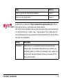
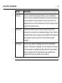
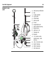
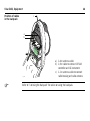
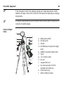
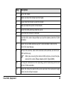
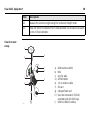
Leica Viva GNSS Getting Started Guide Version 4.5 English 2 Viva GNSS, Introduction Introduction Purpose of this manual Quick references to specific topics To use the product in a permitted manner, please refer to the detailed safety instructions in the Leica CS10/CS15 User Manual, the Leica GS10/GS15 User Manual and the Leica GS25 User Manual. For detailed descriptions of all functions and settings of the product and applications, please refer to the Leica Viva Series Technical Reference Manual. This Getting Started Guide is intended as a quick field reference manual for immediately getting started with your Leica Viva Series equipment. The manual explains what you can find in your container, how everything fits together and how to get started on the basic applications. Topic Refer to What’s in my container? Chapter 1.1 How does the equipment all fit together? Chapter 1.2 What is this first screen I see when I turn on my instrument? Chapter 2.1 How do I get to the Main Menu? Chapter 2.1 How do I select things and move around the screens? Chapter 2.2 What are wizards? Chapter 2.2 Topic Refer to How do I get started with jobs and codelists? Chapter 3 How to use the applications? Chapter 4 myWorld@Leica Geosystems (https://myworld.leica-geosystems.com) offers a wide range of services, information and training material. With direct access to myWorld, you are able to access all relevant services whenever it is convenient for you, 24 hours a day, 7 days per week. This increases your efficiency and keeps you and your equipment instantly updated with the latest information from Leica Geosystems. Service Description myProducts Simply add all Leica Geosystems products that you and your company own. View detailed information on your products, buy additional options or Customer Care Packages (CCPs), update your products with the latest software and keep up-to-date with the latest documentation. Viva GNSS, Introduction 3 4 Viva GNSS, Introduction Service Description myService View the service history of your products in Leica Geosystems Service Centers and detailed information on the services performed on your products. For your products that are currently in Leica Geosystems Service Centers view the current service status and the expected end date of service. mySupport Create new support requests for your products that will be answered by your local Leica Geosystems Support Team. View the complete history of your Support and view detailed information on each request in case you want to refer to previous support requests. myTraining Enhance your product knowledge with the Leica Geosystems Campus - Information, Knowledge, Training. Study the latest online training material or download training material on your products. Keep up-to-date with the latest News on your products and register for Seminars or Courses in your country. Table of Contents In this manual Chapter 1 Equipment 1.1 1.2 1.3 1.4 1.5 1.6 1.7 2 Page Container Contents Setting up as a Post-Processing Base Setting up as a Real-Time Base Setting up as a Real-Time Rover Setting up Viva Uno Using the Backpack Fixing the CS to a Holder and Pole SmartWorx Viva and Principles 2.1 2.2 Viva GNSS, Table of Contents SmartWorx Viva 2.1.1 Screen 2.1.2 Icons 2.1.3 Main Menu 2.1.4 Leica Favourites 2.1.5 Active Assist 2.1.6 Leica Exchange Operating Principles 8 8 19 26 36 47 52 55 59 59 61 65 70 73 76 78 82 5 6 Viva GNSS, Table of Contents 2.3 3 Jobs & Data 3.1 3.2 3.3 4 Webserver 2.3.1 Home 2.3.2 Icons 2.3.3 Go to Work! - Wake-Up 2.3.4 Current Status 2.3.5 Instrument 2.3.6 User Creating a New Job Creating a Codelist Importing ASCII Data into a Job Applications 4.1 4.2 4.3 Survey Stakeout Reference Line Appendix A A.1 A.2 Working with Memory Devices Formatting a Memory Device Directory Structure of the Memory Device Appendix B Uploading System Files 88 88 90 91 92 93 94 95 95 97 101 105 106 109 114 117 117 119 122 Appendix C Viva GNSS, Table of Contents Leica Geo Office 124 7 8 Viva GNSS, Equipment 1 Equipment 1.1 Container Contents Container for GS10 instrument and accessories part 1 of 2 a SYS13_21 f b g h c d e i j a) GS10 instrument b) Single/double arm for antennas of devices c) GFU device such as radio d) Antennas of device e) GAD32 telescopic rod f) GEB221 batteries g) Height hook h) Cables i) Antenna and GAD31 adapter j) SD cards Container for GS10 instrument and accessories part 2 of 2 a SYS13_022 Viva GNSS, Equipment h b c d e i f g j k l a) CS15 field controller b) GHT62 holder for CS field controller on pole c) Allen key d) Supplied stylus e) GHT36 base for telescopic rod f) GAD33 arm 15 cm g) GFU device such as radio h) Manual & DVD i) Tribrach j) GRT146 carrier k) GEB221 battery l) GHT63 clamp 9 10 Viva GNSS, Equipment Container for GS08plus/GS12 instrument and accessories 1/2 a d SYS_038 e f b c a g h a) GS08plus/GS12 GNSS antenna and cable b) GEB211/GEB212 batteries c) CS field controller with CGR radio cap and GHT62 holder for CS field controller on pole d) Allen key e) GHT63 clamp f) Supplied stylus g) GDC221 car adapter h) GAT21/GAT22 antenna Container for GS08plus/GS12 instrument and accessories 2/2 a SYS_039 Viva GNSS, Equipment f b g c d h e i j a) b) c) d) e) f) g) h) i) j) Tribrach SD card/CompactFlash card GRT146 carrier GAD33 arm 15 cm GHT58 tripod bracket for GFU housing Antennas of device GEB171 battery GFU device such as radio Manual & DVD Height hook 11 12 Viva GNSS, Equipment Container for GS15 instrument and accessories part 1 of 2 a f g SYS13_17 b b c h d e i a) b) c) d) e) f) g) h) i) GDC221 car adapter GS15 instrument Cables Tribrach Manuals and DVD TNC QN-adapter GAD31 adapter GRT247 carrier SD cards Container for GS15 instrument and accessories part 2 of 2 ab c d e f g a) b) c) d) e) f) g) SYS13_018 Viva GNSS, Equipment h i j k l GAD108 arm GAD34 arm 3 cm GHT36 base for telescopic rod GEB211/GEB212 batteries Allen key CS field controller GHT62 holder for CS field controller on pole h) Antennas of device i) GAD32 telescopic rod j) Height hook k) GHT63 clamp l) Supplied stylus 13 14 Viva GNSS, Equipment Container for GS25 instrument and accessories part 1 of 2 a b c a) b) c) d) SYS13_036 d e f g h GS25 instrument Antennas of device GAD32 telescopic rod Single/double arm for antennas of devices e) Height hook f) Cables g) Antenna and GAD31 adapter h) SD cards Container for GS25 instrument and accessories part 2 of 2 a SYS_037 Viva GNSS, Equipment h b c d e i f g j k l m a) CS15 field controller b) GHT62 holder for CS field controller on pole c) Allen key d) Supplied stylus e) GHT36 base for telescopic rod f) GAD33 arm 15 cm g) Slot-in device such as radio h) Manual & DVD i) Tribrach j) GRT146 carrier k) GEB212 battery l) GHT63 clamp m) GEB241 battery 15 16 Viva GNSS, Equipment Container for Viva Uno instrument and accessories part 1 of 2 a e SYS13_31 b c f g h i d j a) Antenna and GAD31 adapter b) Manual & DVD c) CS field controller with GS GNSS antenna cap d) Supplied stylus e) Height hook f) GHT62 holder for CS field controller on pole g) GEB211 batteries h) GHT63 clamp i) GDC221 car adapter j) SD cards/CompactFlash cards Container for Viva Uno instrument and accessories part 2 of 2 a b c d a) b) c) d) e) f) e SYS13_32 Viva GNSS, Equipment f g h SD cards/CompactFlash cards GEB211 batteries GRT146 carrier Tribrach Allen key Viva Uno instrument (CS field controller with GS GNSS antenna cap) g) GHT61 hand strap h) Antenna and GAD31 adapter 17 18 Viva GNSS, Equipment Container for GS08plus and accessories a b 002507_003 cd i e j f k d g l m h a) GHT63 clamp b) CS10 field controller with CGR10 radio and GAT21/GAT22 antenna c) GHT62 holder for CS10 field controller on pole d) GEB211/GEB212 batteries e) GS08plus antenna f) SD card/CompactFlash card g) Manual & DVD h) GAD33 arm 15 cm i) Antennas of device j) Supplied stylus k) Allen key l) Cable m) GDC221 car adapter 1.2 Setting up as a Post-Processing Base Use The equipment setups described following are to be used for static operations over markers. Description The instrument can be programmed with the CS field controller before use which can then be omitted from the setup. • • • GNSS antenna/GS08plus instrument/GS12 instrument/GS15 instrument is mounted directly using screw fitting. If using stub and adapter, procedures can vary slightly. When using the adapter and carrier, ensure that the GNSS antenna/GS08plus instrument/GS12 instrument/GS15 instrument and the adapter assembly slide down the full length of the carrier stub. An incorrectly mounted GNSS antenna/GS08plus instrument/GS12 instrument/GS15 instrument will have a direct effect on the results. GNSS antennas are AS05 or AS10. Procedures/setup can vary if AR10, AR25 or AT504 GG is used. If the instrument is left in the container during use in high temperatures, the lid should be left open. Refer to the User Manual for operating and storage temperatures. Viva GNSS, Equipment 19 20 Viva GNSS, Equipment Equipment setup GS10 Use an external battery such as GEB171 to ensure operation for a full day. a b c d e f g h i i j k l GS_107 a) b) c) d) e) f) g) h) i) j) k) l) GNSS antenna AS05/AS10 GRT146 carrier Height hook Tribrach 2.8 m antenna cable GS10 instrument Tripod GEB221 batteries SD card CompactFlash card CS field controller GEB211/GEB212 battery Equipment setup GS08plus/GS12 a b c d e f g h i j h GS_125 Viva GNSS, Equipment a) GS08plus/GS12 instrument b) Height hook c) GRT146 carrier d) Tribrach e) Tripod f) CS field controller (GS08plus only with CS10 field controller) g) GHT61 hand strap h) GEB211/GEB212 battery i) SD card j) CompactFlash card 21 22 Viva GNSS, Equipment Equipment setup GS15 a b c d h i e f g h j k GS_111 a) b) c) d) e) f) g) h) i) j) k) GS15 instrument Height hook GRT247 carrier Tribrach Tripod CS field controller GHT61 hand strap SD card GEB211/GEB212 batteries CompactFlash card GEB211/GEB212 battery Equipment setup GS25 a b c d h e i f g i j k l GS25_012 Viva GNSS, Equipment a) b) c) d) e) f) g) h) i) j) k) l) GNSS antenna AS05/AS10 GRT146 carrier Height hook Tribrach 2.8 m antenna cable GS25 instrument Tripod GEB241 battery SD card CompactFlash card CS field controller GEB211/GEB212 battery 23 24 Viva GNSS, Equipment Equipment setup step-by-step Step Description 1. Set up the tripod. 2. Mount and level the tribrach on the tripod. 3. Ensure that the tribrach is over the marker. 4. Place and lock the carrier in the tribrach. GS10/GS25 GS08plus/GS12/GS15 5. Screw the GNSS antenna onto the carrier. Insert the SD card (only GS15) and the batteries into the GS08plus/GS12/GS15. 6. Check that the tribrach is still level. Screw the GS08plus/GS12/GS15 onto the carrier. 7. Insert the batteries into the instrument. Check that the tribrach is still level. 8. Insert the SD card into the instrument. Insert the SD card or CompactFlash card and the battery into the CS field controller. 9. Connect the instrument to the GNSS antenna using the antenna cable and port ANT on the instrument. Step Description 10. Switch on the CS field controller and connect it to the instrument if necessary. Mandatory for the GS08plus/GS12 and optional for the GS10/GS15/GS25. Viva GNSS, Equipment 11. To hang the instrument on the tripod leg, use the hook on the rear of the unit. Or place the instrument in the container. 12. Insert the height hook into the carrier. 13. Measure the antenna height using the height hook. 14. Press the ON/OFF button on the instrument for at least 2 s (GS25: 3 s) to switch on the instrument . To hang the CS field controller on the tripod leg, use the hook on the hand strap. Refer to the CS10/CS15 User Manual. 25 26 Viva GNSS, Equipment 1.3 Setting up as a Real-Time Base Use The equipment setups described following are to be used for real-time base stations with the need of optimal radio coverage. Raw observation data can also be collected for post-processing. Description The GS10/GS25 instrument clips to the tripod leg. Connections are made to the GNSS and radio antenna. The radio antenna is mounted on the antenna arm which clips to the GNSS antenna. The GS10/GS15/GS25 instrument can be programmed with the CS field controller before use which can then be omitted from the setup. The GS10/GS25 instrument can be used as a DGPS base station, if fitted with the DGPS option, and as a real-time base station. The connection between GS15 and CS field controller is made via Bluetooth. • • GNSS antenna/GS08plus instrument/GS12 instrument/GS15 instrument is mounted directly using screw fitting. If using stub and adapter, procedures can vary slightly. When using the adapter and carrier, ensure that the GNSS antenna/GS08plus instrument/GS12 instrument/GS15 instrument and the adapter assembly slide down the full length of the carrier stub. An incorrectly mounted GNSS antenna/GS08plus instrument/GS12 instrument/GS15 instrument will have a direct effect on the results. • • Standard radio is used throughout the instructions. Digital cellular phones can also be used but the setup can differ slightly. GNSS antennas are AS05 or AS10. Procedures/setup can vary if AR10, AR25 or AT504 GG is used. If the instrument is left in the container during use in high temperatures, the lid should be left open. Refer to the User Manual for operating and storage temperatures. Use an external battery such as GEB171 to ensure operation for a full day. Viva GNSS, Equipment 27 28 Viva GNSS, Equipment Equipment setup GS10 a b c d e k a) b) c) d) e) f) g) l f g m h i m n j o p GS_108 h) i) j) k) l) m) n) o) p) Radio antenna GAD33 arm 15 cm GNSS antenna AS05/AS10 Height hook GRT146 carrier Tribrach 1.2 m antenna cable (instrument/GNSS antenna) Tripod GS10 instrument Radio in housing 1.2 m antenna cable (radio housing/radio antenna) GEB221 batteries SD card CompactFlash card CS field controller GEB211/GEB212 battery Equipment setup GS08plus/GS12 f a) b) i c) j d) e) k f) l g) h) m i) g n a b c d e h GS_130 Viva GNSS, Equipment GS08plus/GS12 instrument Height hook GRT146 carrier Tribrach Antenna for device Tripod GHT58 tripod bracket GFU radio modem CS field controller (GS08plus only with CS10 field controller) j) GEB211 / GEB212 battery k) SD card l) CompactFlash card m) GEB171 external battery n) GEV205 Y-cable 29 30 Viva GNSS, Equipment Equipment setup GS15 l a b c d e f g h i h j k GS_117 a) GS15 instrument with RTK slot-in device b) Height hook c) GRT247 carrier d) Tribrach e) Tripod m f) CS field controller n g) GHT61 hand strap h) SD card i) GEB211/GEB212 batteries o j) CF card k) GEB211/GEB212 battery p e l) GAD109 transition adapter m) RTK antenna n) GAD34 arm 3 cm o) GAD32 telescopic rod p) GHT36 base for telescopic rod Equipment setup GS25 a b c d e f g h i j k l l m n o GS25_013 Viva GNSS, Equipment a) b) c) d) e) f) g) h) i) j) k) l) m) n) o) Radio antenna GAD33 arm 15 cm GNSS antenna AS05/AS10 Height hook GRT146 carrier Tribrach 1.2 m antenna cable (instrument/GNSS antenna) Tripod GS25 instrument 1.2 m antenna cable (radio housing/radio antenna) GEB241 battery SD card CompactFlash card CS field controller GEB211/GEB212 battery 31 32 Viva GNSS, Equipment Equipment setup step-by-step Step Description 1. Set up the tripod. 2. Mount and level the tribrach on the tripod. 3. Ensure that the tribrach is over the marker. 4. Place and lock the carrier in the tribrach. GS10/GS25 GS08plus/GS12 GS15 5. Screw the GNSS antenna onto the carrier. Screw the GS08plus/GS12 onto the carrier. Insert the SD card and the batteries into the GS15. 6. Check that the tribrach is still level. Press the ON/OFF button on the instrument for at least 2 s to switch on the instrument. 7. Insert the SD card and the batteries into the instrument. Screw the GS15 onto the carrier. Hang the external battery onto a tripod leg. Viva GNSS, Equipment Step Description 8. Connect the instrument to the GNSS antenna using the antenna cable and port ANT on the instrument. 9. Connect the CS field Connect the GEV205 controller to the instru- cable to the ment if necessary. GS08plus/GS12, to the external battery and to the radio housing. 10. To hang the instrument on the tripod leg, use the hook on the rear of the unit. Or place the instrument in the container. Hang the tripod bracket Check that the tribrach is still level. onto a tripod leg and attach the radio housing onto the tripod bracket. Insert the SD card or CompactFlash card and the battery into the CS field controller. Insert the SD card or Connect the CS field CompactFlash card and controller to the instruthe battery into the CS ment if necessary. field controller. 33 34 Viva GNSS, Equipment Step Description 11. Insert the height hook into the carrier. 12. Insert the height hook Measure the antenna To hang the CS field height using the height controller on the tripod into the carrier. hook. leg, use the hook on the hand strap. Refer to the CS10/CS15 User Manual. 13. Clip the antenna arm to Insert the height hook the GNSS antenna. into the carrier. 14. Screw the radio antenna onto the antenna arm. Connect the CS field To hang the CS field controller to the instru- controller on the tripod ment if necessary. leg, use the hook on the hand strap. Refer to the CS10/CS15 User Manual. Measure the antenna height using the height hook. Measure the antenna Press the ON/OFF height using the height button on the instruhook. ment for at least 2 s to switch on the instrument. Viva GNSS, Equipment Step Description 15. GS10 Attach the radio in its housing to port P2 or P3 on the instrument. GS25 Insert the slot-in radio into port P3 on the instrument. 16. Connect the radio antenna to the radio using the second 1.2 m antenna cable. - 17. Press the ON/OFF button on the instrument for at least 2 s (GS25: 3 s) to switch on the instrument. - Press the ON/OFF button on the instrument for at least 2 s to switch on the instrument. 35 36 Viva GNSS, Equipment 1.4 Setting up as a Real-Time Rover Use The following equipment setups are to be used for real-time rover with extended periods of use in the field. Description The radio attaches to the instrument (GS10) or is inserted into the instrument (GS25) and is placed in the backpack. Connections are made to the GNSS antenna, radio antenna and CS field controller. The cables coming from the backpack can be disconnected when an obstacle such as a fence has to be crossed. The CS field controller is fixed to the pole with the GHT62. Connection between the GS12/GS15/GS08plus instrument and the CS field controller is made through Bluetooth. • • • GNSS antenna/GS12 instrument/GS15/GS08plus instrument is mounted directly using screw fitting. If using stub and adapter, procedures can vary slightly. When using the pole with stub, ensure that the GNSS antenna/GS12 instrument/GS15/GS08plus instrument and the screw-to-stub adapter slide down the full length of the stub before tightening the locking ring. An incorrectly mounted GNSS antenna/GS12 instrument/GS15/GS08plus instrument will have a direct effect on the results. Aluminium poles are used. They can be replaced with their carbon fibre equivalent without any change to these instructions. • • Viva GNSS, Equipment Standard radio is used throughout the instructions. Digital cellular phones can also be used but the setup can differ slightly. GNSS antennas are AS05 or AS10. Procedures/setup can vary if AR10, AR25 or AT504 GG is used. 37 38 Viva GNSS, Equipment Equipment setup GS10 a j k b l f c g h m d e n o p i q g r GS_101 a) b) c) d) e) f) g) h) i) j) k) l) m) n) GNSS antenna AS05/AS10 Pole CS field controller Grip for pole GHT62 holder Antenna cable SD card CompactFlash card GEB211/GEB212 battery Radio antenna GAD34 arm 3 cm Telescopic rod Backpack 1.2 m antenna cable (radio housing - radio antenna) o) 1.8 m, CS to GS10 cable p) Radio in housing q) GEB221 batteries r) GS10 instrument Equipment setup GS12 a f b g h c i d f e GS_124 Viva GNSS, Equipment a) b) c) d) e) f) g) h) i) GS12 GNSS antenna CGR15 radio Grip for pole GHT62 holder Pole GEB211/GEB212 battery SD card CompactFlash card CS field controller 39 40 Viva GNSS, Equipment Equipment setup GS15 f a b g h i h j c k d i e GS_116 a) b) c) d) e) f) g) h) i) j) k) GS15 instrument RTK slot-in device Grip for pole GHT62 holder Pole RTK antenna GAD108 arm SD card GEB211/GEB212 batteries CompactFlash card CS field controller Equipment setup GS25 a j k b l f c g h m d e n o g i p P4 P1 E2 q GS25_014 Viva GNSS, Equipment a) b) c) d) e) f) g) h) i) j) k) l) m) n) GNSS antenna AS05/AS10 Pole CS field controller Grip for pole GHT62 holder Antenna cable SD card CompactFlash card GEB211/GEB212 battery Radio antenna GAD34 arm 3 cm Telescopic rod Backpack 1.2 m antenna cable (radio housing - radio antenna) o) GEB241 battery p) GS25 instrument q) 1.8 m, CS to GS25 cable 41 42 Viva GNSS, Equipment Equipment setup GS08plus a b c f g h d i e f GS_126 a) b) c) d) e) f) g) h) i) GS08plus instrument Pole CGR10 radio Grip for pole GHT62 holder GEB211/GEB212 battery SD card CompactFlash card CS10 field controller Equipment setup step-by-step Step Description 1. Attach the GHT62 holder to the pole. Refer to "1.7 Fixing the CS to a Holder and Pole". 2. Insert the SD card or CompactFlash card and the battery into the CS field controller. 3. For real-time setup with radio (GS12/GS15): Attach the CGR radio to the CS field controller. Refer to the CS10/CS15 User Manual. 4. Clip the CS field controller into the holder and lock it by pushing the locking pin into the locked position. 5. Press ON/OFF button on the CS field controller to switch on. Proceed with step 6. for GS10/GS25 and with step 25. for GS12/GS15/GS08plus. Viva GNSS, Equipment 6. Screw the GNSS antenna to the top of the pole. 7. Insert the SD card and the batteries into the instrument. 8. GS10 Attach the radio in its housing to port P2 or P3 on the instrument. GS25 Insert the slot-in radio into port P3 on the instrument. 43 44 Viva GNSS, Equipment Step Description 9. Place the instrument in the backpack with the top side facing outwards and the instrument front panel to the top. 10. Fasten the strap around the instrument. 11. Push the telescopic rod through the slit in the top of the backpack. Ensure that it is located in the sleeve inside the backpack and push it all the way to the bottom. 12. Adjust the height of the telescopic rod to suit. 13. Screw the radio antenna arm onto the telescopic rod. 14. Connect the first 1.2 m antenna cable to the radio antenna. 15. Pass the cable through the opening in the top of the backpack and down underneath the instrument. 16. Connect the first 1.2 m antenna cable to the radio. 17. Connect the 1.6 m antenna cable to port ANT on the instrument. 18. Pass the 1.6 m antenna cable through a cable brake and down through the opening in the bottom corner of the backpack flap. Refer to "Position of cables in the backpack". 19. Draw the required amount of cable out of the backpack and tighten the cable brake. Step Description 20. Connect one end of the second 1.2 m antenna cable to the loose end of the 1.6 m antenna cable and the other end to the GNSS antenna. 21. Connect the 1.8 m, CS to GS cable to the CS field controller. 22. Pass the 1.8 m, CS to GS cable through the opening in the bottom corner of the backpack flap and up through a cable brake. Refer to "Position of cables in the backpack". 23. Plug it into port P1 on the instrument. 24. Press ON/OFF button on the instrument to switch on. GS12/GS15/GS08plus. Viva GNSS, Equipment 25. Insert the SD card (only GS15) and the batteries into the GS12/GS15/GS08plus. 26. Press ON/OFF button on the GS12/GS15/GS08plus to switch on. 27. Screw the GS12/GS15/GS08plus to the top of the pole. 28. CS field controller and GS12/GS15/GS08plus are connected via Bluetooth. 45 46 Viva GNSS, Equipment Position of cables in the backpack c a b GS_112 a) 1.6 m antenna cable b) 1.8 m cable to connect CS field controller and GS instrument c) 1.2 m antenna cable to connect radio housing and radio antenna Refer to "1.6 Using the Backpack" for advice on using the backpack. 1.5 Setting up Viva Uno Use The equipment setups described following are to be used for static operations over markers or for rover with extended periods of use in the field. Description The Viva Uno instrument consists of the CS field controller (CS10/CS15) and the GS GNSS antenna cap (GS05/GS06) attached to the CS field controller. The CS field controller with the GS GNSS antenna cap attached, clips to the tripod leg. Connections are made to the external GNSS antenna. The CS field controller with the GS GNSS antenna cap attached is fixed to the pole with the GHT62. The setup can be used as a DGPS rover, if fitted with the DGPS option. • • GNSS antenna is mounted directly using screw fitting. If using stub and adapter, procedures can vary slightly. When using the adapter and carrier, ensure that the GNSS antenna and the adapter assembly slide down the full length of the carrier stub. An incorrectly mounted GNSS antenna will have a direct effect on the results. GNSS antenna is AS05. Viva GNSS, Equipment 47 • 48 Viva GNSS, Equipment Viva Uno tripod setup If the instrument is left in the container during use in high temperatures, the lid should be left open. Refer to the CS10/CS15 User Manual for operating and storage temperatures. It is always recommended to use the external GNSS antenna (AS05) to optimise the reception of satellite signals. a g b c d e h i j f k l GS_119 a) b) c) d) e) f) g) h) i) j) k) l) GNSS antenna AS05 GRT146 carrier Tribrach GHT196 tribrach bracket for height meter GHM007 instrument height meter Tripod 1.2 m antenna cable SD card CompactFlash card Viva Uno instrument (CS field controller with GNSS cap) GHT61 hand strap GEB211/GEB212 battery Step Description 1. Set up the tripod. 2. Mount and level the tribrach on the tripod. 3. Ensure that the tribrach is over the marker. 4. Place and lock the carrier in the tribrach. 5. Screw the GNSS antenna onto the carrier. 6. Check that the tribrach is still level. 7. Insert the SD card or CompactFlash card and the battery into the CS field controller. 8. Attach the GS GNSS antenna cap to CS field controller. Refer to the CS10/CS15 User Manual. 9. Connect the antenna cable to the external GNSS antenna and to the GS GNSS antenna cap. When you are using the external GNSS antenna, ensure that you selected the correct Rover antenna (AS05 Tripod GHM). Viva GNSS, Equipment 10. To hang the instrument on the tripod leg, use the hand strap on the rear of the CS field controller. 11. Attach the tribrach bracket to the carrier and insert the instrument height meter into the tribrach bracket. 49 50 Viva GNSS, Equipment Step Description 12. Measure the antenna height using the instrument height meter. 13. Press the ON/OFF button on the CS field controller for at least 2s to switch on the CS field controller. Viva Uno rover setup a b e f g c h d i GS_118 a) b) c) d) e) f) g) h) i) GNSS antenna AS05 Pole Grip for pole GHT62 holder 1.2 m antenna cable SD card CompactFlash card Viva Uno instrument (CS field controller with GS GNSS cap) GEB211/GEB212 battery Step Description 1. Attach the GHT62 holder to the pole. Refer to "1.7 Fixing the CS to a Holder and Pole". 2. Insert the SD card or CompactFlash card and the battery into the CS field controller. 3. Attach the GS GNSS antenna cap to CS field controller. Refer to the CS10/CS15 User Manual. 4. Clip the CS field controller into the holder and lock it by pushing the locking pin into the locked position. 5. Screw the GNSS antenna to the top of the pole. 6. Adjust the height of the telescopic rod to suit. 7. Connect the antenna cable to the external GNSS antenna and to the GS GNSS antenna cap. When you are using the external GNSS antenna, ensure that you selected the correct Rover antenna (AS05 Tripod GHM). 8. Viva GNSS, Equipment Press ON/OFF button on the CS field controller to switch on. 51 52 Viva GNSS, Equipment 1.6 Using the Backpack Use The backpack is used for various applications. The applications are: • Post-processed kinematic, pole and backpack. • Real-time rover, pole and backpack. Ensures that the antenna pole does not sway around and remains as upright as possible. Antenna pole strap Pass the strap around the pole and fasten using the clip as shown in the diagram. GS_105 The hip belt • transfers most of the weight from the shoulders to the hips when properly adjusted. • contains velcro attachments through which cables can be passed. Hip belt GS_102 The internal net pouch is designed for • carrying an AS05/AS10 antenna when not in use. • storing coiled cables. • carrying a non-standard radio. • carrying spare batteries. • carrying sandwiches. Internal net pouch GS_103 Viva GNSS, Equipment 53 54 Viva GNSS, Equipment Use in high temperatures In high temperatures, it is desirable to increase air flow around the instrument. Therefore the backpack can be kept half or even fully open when in use. GS_104 GS_106 To 1) 2) 3) half open the backpack: Open the backpack halfway. Tuck the flap inside. Secure it with the velcro pad. To 1) 2) 3) open the backpack completely: Open the backpack completely. Secure it with the velcro pad. Tuck the flap under the instrument. 1.7 Fixing the CS to a Holder and Pole Components of the GHT62 holder The GHT62 holder consists of some components, as shown in the diagram. d e f g a b c h i GHT63 clamp a) Plastic sleeve b) Pole clamp c) Clamp bolt GHT62 holder d) Locking pin e) Top clip f) Mounting plate (extendable) g) Bottom clip h) Tightening screw i) Mounting arm TS_058 Viva GNSS, Equipment 55 56 Viva GNSS, Equipment Fixing the CS field controller and GHT62 to a pole step-by-step Step Description If you use the CS15 field controller, extend the mounting plate of the holder first. For an aluminium pole, fit the plastic sleeve to the pole clamp. 1. Insert the pole into the clamp hole. 2. Attach the holder to the clamp using the clamp bolt. 3. Adjust the angle and the height of the holder on the pole to a comfortable position. 4. Tighten the clamp with the clamp bolt. 5. Before the CS field controller is placed onto the mounting plate, ensure that the locking pin is put into the unlocked position. To unlock the locking pin, push the locking pin to the left. 6. Hold the CS field controller above the holder and lower the end of the CS field controller into the mounting plate. TS_055 Step Description 7. Apply slight pressure in a downward direction and then lower the top part of the CS field controller until the unit is clicked into the holder. The guides of the mounting plate aid in this action. TS_056 8. After the CS field controller is placed onto the mounting plate, ensure that the locking pin is put into the locked position. To lock the locking pin, push the locking pin to the right. TS_054 Viva GNSS, Equipment 57 58 Viva GNSS, Equipment Detaching the CS from a pole stepby-step Step Description 1. Unlock the locking pin by pushing the locking pin to the left of the mounting plate. 2. Place palm over the top of the CS until fingers grip the bar of the holder underneath. 3. Push from the top of the CS toward the bar of the holder. 4. While in this position, lift the top of the CS from the holder. 1 TS_057 2 2 SmartWorx Viva and Principles 2.1 SmartWorx Viva Keyboard display CS15 F1 F2 a b c d e f g F3 k l m OK n Fn h 1 2 3 4 5 6 7 8 9 F11 F9 W A E S Z R D X F10 T F C p F12 F8 Q o . 0 F7 i j F6 F5 F4 V B K J H N M P O I U Y G L q r s Viva GNSS, SmartWorx Viva and Principles a) b) c) d) e) f) g) h) i) j) k) l) m) n) o) p) q) r) s) Home Arrow keys, OK ON/OFF Fn ± key Numeric keys Brightness Keyboard illumination Function keys F7 - F12 CAPS Lock Function keys F1 - F6 Favourites ESC ENTER Backspace Volume Alpha keys ENTER SPACE 59 60 Viva GNSS, SmartWorx Viva and Principles Start using SmartWorx Viva • • Turn on your GS GNSS or TPS instrument. Turn on your CS field controller and start SmartWorx Viva. For information about wizards refer to "Wizards". 2.1.1 Screen - CS15 field controller Screen a b f c g h i d e SYS13_025 Elements a) b) c) d) e) f) g) h) i) Element Description Time The current local time is shown. Title Name of the screen is shown. Screen area The working area of the screen. Message line Messages are shown for 10 s. Viva GNSS, SmartWorx Viva and Principles Icons Title Screen area Message line Softkeys ESC Fn CAPS Time 61 62 Viva GNSS, SmartWorx Viva and Principles Common softkeys Element Description Icons Shows status information of the instrument. Refer to "2.1.2 Icons". Can be used with touch screen. ESC Can be used with touch screen. Same functionality as the fixed key ESC. The last operation will be undone. Entry mode The caps mode for upper case letters is active. The caps mode is activated and deactivated by pressing the CAPS key. Fn Switches between the first and second level of function keys. Softkeys Commands can be ran using F1-F6 keys (only applicable for CS15 field controller). The commands assigned to the softkeys are screen-dependent. Can be used directly with touch screen. The softkeys following are used commonly in the Leica SmartWorx Viva software across all applications. Softkey Function Key Description OK (F1) To select the highlighted option and to continue with the subsequent screen. Key combinations Softkey Function Key Description Page (F6) To change to another page on the current screen. Help Fn (F1) To open the Leica SmartWorx Viva online help. Home Fn (F2) To move the focus to the top of the list shown in the current screen. End Fn (F3) To move the focus to the bottom of the list shown in the current screen. Quit Fn (F6) To exit the current application and return to the screen from where the application was accessed. Key Function Fn + 4 Hold Fn while pressing 4. Increase the screen brightness. Fn + 7 Hold Fn while pressing 7. Decrease the screen brightness. Fn + 6 Viva GNSS, SmartWorx Viva and Principles Hold Fn while pressing 6. Increase the volume for acoustic warning signals, beeps and keypresses on the CS field controller. 63 64 Viva GNSS, SmartWorx Viva and Principles Key Function Fn + 9 Fn + 0 Fn + . Hold Fn while pressing 9. Decrease the volume for acoustic warning signals, beeps and keypresses on the CS field controller. Hold Fn while pressing 0. If keyboard illumination is already off: Turns on keyboard illumination. If keyboard illumination is already on: Turns off keyboard illumination. Hold Fn while pressing .. Take a screenshot of the current SmartWorx Viva screen. Refer to "Taking a screenshot". 2.1.2 Icons Description The screen icons display the status information of the instrument. Icon bar - GNSS Mode The icons provide information related to basic instrument functions. The icons that appear depend upon which instrument is used and the current instrument configuration. a b c d e f g h i SYS13_023 f) a) GNSS position status g) b) Number of visible satellites c) Number of satellites contributing to position solution d) Real-time device and real-time status h) e) Current active instrument i) Viva GNSS, SmartWorx Viva and Principles Camera Internet online status (CS field controller), Active Assist service or Leica Exchange service Memory storage (SD card/CompactFlash card/USB stick/internal memory) or Line/area/auto points Battery level (field controller/instrument) 65 66 Viva GNSS, SmartWorx Viva and Principles Icons Icon Description Position status Displays the status of the current position. As soon as this icon becomes visible the instrument is in a stage where practical operation can commence. Number of visible satellites Displays the number of theoretically visible satellites above the configured cut-off angle according to the current almanac. Contributing satellites Displays the number of satellites that are contributing to the currently computed position solution. The number of contributing satellites can differ from the number of visible satellites. This difference can be because satellites cannot be viewed, or because the observations to these satellites are considered too noisy to be used. Real-time device Displays the real-time device configured to be used. Icon Description Real-time status Displays the status of the real-time device configured to be used. Current active instrument Displays the instruments that are currently configured and active. When more than one instrument is configured, the instrument at the front of the icon is the active instrument. Camera Select this icon to begin the camera function. Internet online status Displays the Internet online status of the CS field controller. Leica Exchange service Displayed when the CS field controller is connected to the Leica Exchange service. Viva GNSS, SmartWorx Viva and Principles 67 68 Viva GNSS, SmartWorx Viva and Principles Icon Description Active Assist service Displayed when the CS field controller is connected to the Active Assist service. Memory storage Displays the status of the internal memory or data storage device. Data management Select this icon to open the data management pages for Points, Lines or Areas. If there are open lines or areas, a symbol will appear in the icon. Battery Displays the status and location of the battery. TPS specific icons Icon Description Automatic aiming Displays the current automatic aiming or PowerSearch settings. Prism Displays the selected prism. Measure mode Displays the selected measurement mode. The red laser icon will display when the red laser is active. Compensator level and Instrument face I or II Displays the compensator is off or out of range icons, or the instrument face I or II icon. Viva GNSS, SmartWorx Viva and Principles 69 70 Viva GNSS, SmartWorx Viva and Principles 2.1.3 Main Menu Main Menu OK To select the highlighted option and to continue with the subsequent screen. Map To open Tap Map. Fn Mode To switch between GPS and TPS modes Fn Exit To close Leica SmartWorx Viva software. Main Menu functions Main Menu function Description Go to Work! • To select and start an application. Jobs & Data • To manage jobs, data, codelists, GNSS antennas, reflectors and coordinate systems. • To export data from a job on the instrument to a file on the memory device in a customised ASCII format or in DXF format. • To import ASCII, GSI or DXF data from a file on the memory device to a job on the instrument. • To copy points between jobs. Instrument • To access all configuration parameters related to a survey, the instrument and the interfaces. • To view the various instrument status screens. • For TS11/TS15: To configure the camera, if available. Viva GNSS, SmartWorx Viva and Principles 71 Viva GNSS, SmartWorx Viva and Principles Main Menu function 72 Description User • To format the memory device. • To upload files relevant for the instrument functionality, for example, firmware files, language files and licence keys. • To transfer data between the memory device and a standard and simple FTP server. • To view files on the memory device or the internal memory. • To access all configuration parameters individualising the system and the working style. • For TS11/TS12 Lite/TS15: To check and adjust the compensator, index error and line of sight error. 2.1.4 Leica Favourites Description Frequently used settings can be accessed and changed quickly through the Leica TPS Favourites and Leica GPS Favourites screens. The change is applied immediately and the workflow is not interrupted. The screens display selectable icons for quick check functions or for available settings to change to. Access For • For • TPS: Tap the target aiming icon or select GPS: Tap the position status icon or select . . Leica TPS Favourites OK To apply the selected setting or to access the selected function. Fn Quit To exit the screen. Viva GNSS, SmartWorx Viva and Principles 73 74 Viva GNSS, SmartWorx Viva and Principles To change to one of the displayed settings, or access a quick check function, do one of the following; • Tap on the icon on the touch screen. • Highlight a field and press . • Highlight a field and press • • Highlight a field and press OK. Press the number next to the setting or function. OK . Leica GPS Favourites OK To apply the selected setting or to access the selected function. Fn Quit To exit the screen. To change to one of the displayed settings, or access a quick check function, do one of the following; • Tap on the icon on the touch screen. • Highlight a field and press . • Highlight a field and press • • Highlight a field and press OK. Press the number next to the setting or function. Viva GNSS, SmartWorx Viva and Principles OK . 75 76 Viva GNSS, SmartWorx Viva and Principles 2.1.5 Active Assist Description Active Assist is an online support tool that allows Leica technical support to gain remote access to your TS11/TS12 Lite/TS15 instrument or CS10/CS15 field controller. Valid CCP and Active Assist licences are required to use Active Assist. Active Assist can only be started from the Leica TPS Favourites and Leica GPS Favourites screens. Refer to "2.1.4 Leica Favourites". Access Using Active Assist step-by-step Step Description 1. Establish a connection to the Internet through a Bluetooth digital cellular phone or the internal 3.5G modem of the CS10/CS15 field controller. 2. Call your local technical support. Step Description 3. Select Start Active Assist to connect to the Active Assist service. 4. Quote the equipment number shown on the screen to your supporter. 5. Leica technical support has now remote access to your TPS instrument or CS field controller screen. Select End Active Assist to disconnect from the Active Assist service once the session has finished. Viva GNSS, SmartWorx Viva and Principles 77 Viva GNSS, SmartWorx Viva and Principles 78 2.1.6 Leica Exchange Description Leica Exchange is an online service that allows the data exchange between two users of the service. For example: • The user in the field sends the daily measured data to the user in the office. • The user in the field sends a codelist to a second user in the field. The service is available on your TS11/TS12 Lite/TS15 instrument or CS10/CS15 field controller. Requirements • Valid Leica Exchange subscription • SmartWorx Viva 4.0 or higher • Leica Exchange licence key loaded on a CS field controller/TS instrument AND / OR • Leica Exchange entitlement ID loaded on a computer with Leica Exchange Office Creating User name and Password stepby-step Step Description 1. Order a Leica Exchange subscription. You will receive a subscription form. 2. Take the subscription ID in the subscription form and log in to your myWorld account (https://myworld.leica-geosystems.com). 3. Navigate to myTrustedServices. Step Description 4. On the My Trusted Services tab, select Add Service and type in the subscription ID. 5. The Leica Exchange Service is shown in the My Trusted Services tab. Once the Leica Exchange Service is registered, users can be assigned to the service on the My Users tab. 6. Click the Add button to define a new user and to assign services to the user. For each user: • Enter contact information • Define a unique user name • Assign a password The user name and password are needed each time you access the Leica Exchange Service. The Leica Exchange Service can be accessed from SmartWorx Viva in the field or using Leica Exchange Office PC software. After registering the subscription ID in your myWorld account, the subscription usage statistic is fully accessible. The total quota is shown and the consumed and remaining GB are displayed in total GB and GB/month. Viva GNSS, SmartWorx Viva and Principles 79 80 Viva GNSS, SmartWorx Viva and Principles Leica Exchange can be started from the Tools & Utilities menu or directly by pressing a Hot key (only for CS15 field controller). Access If a user is currently logged in, the Leica Exchange Main Menu screen is accessed. If no user is currently logged in, the Leica Exchange screen is accessed. Using Leica Exchange service step-by-step Step Description 1. Establish a connection to the Internet through a Bluetooth digital cellular phone or the internal 3.5G modem of the CS10/CS15 field controller. 2. Log in to the Leica Exchange service. User name and password must be typed in each time the Leica Exchange service is accessed. A license agreement has to be accepted, when you log in to Leica Exchange for the first time. The Leica Exchange Main Menu is accessed. Step Description 3. Select the option you want to perform: • Send data.. • Get data.. • Transfer status.. • Config.. • Connection status.. • Exit & stay logged in • Exit & log out 4. Select Exit & log out to disconnect from the Leica Exchange service to return to the Main Menu. If you only want to return to the Main Menu, but remain logged in, select Exit & stay logged in. Viva GNSS, SmartWorx Viva and Principles 81 82 Viva GNSS, SmartWorx Viva and Principles 2.2 Accessing a menu option Operating Principles Description Illustration There are three ways to access a menu option. 1 Using the touchscreen functionality. Tap on the menu item using the stylus provided. 2 Using the up and down navigation arrows. Move the focus to the menu item. Select OK, or press the OK button, or the ENTER button. OK 3 Using the numbered keypad. Select the number that corresponds to the menu item. For example, press 1 from the Jobs & Data menu to access the New job screen. Accessing a selectable list Description Illustration A downward arrow beside a field, indicates there are more choices available in a selectable list. A box and a downward arrow beside a field, indicates that there are more choices and functionality available in a separate screen. To access the list or screen use the touchscreen functionality to tap on the icon, or move the focus to the field and press the ENTER button. Accessing a page within a screen Description Illustration To access another page within a screen, either: • Tap on the page tab for the page to be displayed, or • Select Page until the page is displayed Viva GNSS, SmartWorx Viva and Principles 83 84 Viva GNSS, SmartWorx Viva and Principles Exiting a screen without making a change Wizards Description Illustration To exit a screen without making a change, either: • Tap on the return icon, or • Press the ESC button The wizards following are available to make your daily work easier. Each of them lead you through a series of steps, performing tasks in a specific sequence. For detailed descriptions of the wizards, please refer to the Leica Viva Series Technical Reference Manual. Wizard Description SmartWorx StartUp Wizard Define the behaviour of your instrument for a general start-up. RTK rover wizard Set up your real-time rover. GS connection wizard Connect your CS field controller with your GS instrument. TPS connect wizard Connect your CS field controller with your TPS instrument. Taking an image using the instruments camera Wizard Description Internet wizard Connect your CS field controller with the Internet. CS connection wizard Connect your CS field controller with your TS11/TS12 Lite/TS15 instrument. Working style wizard Configure the parameters and functions of SmartWorx Viva so that it suits to your preferred method of working and save the settings in a working style. Check & Adjust Wizard For TS11/TS12 Lite/TS15. Check and adjust the instrument in the field by running through specific measurement procedures. Step 1. Description Tap the camera icon in the icon bar to access the Capture Image with Camera screen. For a CS field controller, which is configured to use a TS11/TS15 instrument with a wide-angle camera, the Capture Image with Camera screen has two pages (TS wide-angle and CS camera). Select which camera to use by clicking the corresponding page or using Page to toggle between both pages. 2. Aim the camera to the desired target. Viva GNSS, SmartWorx Viva and Principles 85 86 Viva GNSS, SmartWorx Viva and Principles Step Description 3. Check the view at the display. 4. Press OK or click Cpture to take the picture. 5. Cpture changes to Store. The image can be overlaid with a sketch. Click the icon in the toolbar to activate sketching. The icon is displayed. Additional icons are displayed to control the line weight, style and colour of any lines you "sketch" on top of your image. The image cannot be moved. 6. Press Store to save the image. A confirmation window opens. The image can be linked to a point, line or area. 7. • • • Press Last to link the image with the last stored point and save it. Press Select to link the image with any point, line or area of the current working job and save it. Press No to save the image in the current working job without linking it to a point, line or area. After the image has been stored you automatically return to the Capture Image with Camera screen. Taking a screenshot Step Description 1. Press the hotkey configured to User - Screenshot capture or hold Fn while pressing ’.’. A screenshot of the current SmartWorx Viva screen is created and displayed in the Image Notes screen. The hotkey functionality is not available on the CS10 field controller. 2. The screenshot can be overlaid with a sketch. Click the icon in the toolbar to activate sketching. The icon is displayed. Additional icons are displayed to control the line weight, style and colour of any lines you "sketch" on top of your image. The image cannot be moved. 3. Press Store to save the screenshot. A confirmation window opens. The screenshot can be linked to a point, line or area. 4. • • • Press Last to link the screenshot with the last stored point and save it. Press Select to link the screenshot with any point, line or area of the current working job and save it. Press No to save the screenshot in the current working job without linking it to a point, line or area. After the screenshot has been stored you automatically return to the screen where the screenshot has been taken from. Viva GNSS, SmartWorx Viva and Principles 87 88 Viva GNSS, SmartWorx Viva and Principles 2.3 Webserver Description The Web server is a web-based tool to view the status of and configure the GNSS instruments. The Web server application is integrated into the GS firmware and cannot be deleted. Access The Web server from the GNSS instruments can be accessed using the web browser of a Windows device. The Windows device has to be connected first to the GNSS instrument via cable or Bluetooth. Refer to the Leica GS10/GS15 User Manual and the Leica GS25 User Manual. 2.3.1 Home Description Home function Description Go to Work! • To select and start the Wake-up application. Refer to "2.3.3 Go to Work! - Wake-Up". Home function Description Current Status • To view GNSS information of the GS as well as the instrument firmware. Refer to "2.3.4 Current Status". Instrument • To configure settings for the GS. Refer to "2.3.5 Instrument". User • Viva GNSS, SmartWorx Viva and Principles To upload and activate firmware, licence keys and languages. Refer to "2.3.6 User". 89 90 Viva GNSS, SmartWorx Viva and Principles 2.3.2 Icon bar Icons a b c d e f SYS13_029 a) b) c) d) e) f) GNSS position status Number of satellites tracked and available for each satellite system Real-time device and real-time status Internet online status Memory storage (SD card only) Battery level on GS 2.3.3 Go to Work! - Wake-Up Description Wake-up sessions are static point occupations, for which the instrument is preprogrammed with a start time and a duration or end time. The instrument turns itself on at the configured start time and the point occupation begins. The point occupation stops and the point is stored after the preprogrammed duration. In the Go to Work! - Wake-Up menu, the actions following can be performed: • Create/edit a Wake-up session. • Activate/deactivate a Wake-up session. • Delete a Wake-up session. A data storage device must be inserted when the instrument wakes up. If no data storage device is fitted or it is damaged, not formatted or full then the session will not be run. Viva GNSS, SmartWorx Viva and Principles 91 Viva GNSS, SmartWorx Viva and Principles 92 2.3.4 Current Status Description In the Current Status menu, the statuses following can be viewed: • Satellite Tracking status – Date and time of the various almanacs on the instrument – Sat, Elevation, Azimuth, S/N1 and S/N2 and Health of every satellite • Position status – Local time, Position latency, HDOP, VDOP, GDOP, PDOP, Position quality and Height quality (only available if a calculated position is available) • Battery/memory/raw data logging status – Percentage of remaining power capacity of the internal and/or external battery (if connected) – Total/free memory for data storage on the SD card – Information about the raw data logging • Instrument status – Instrument and firmware (e.g. Serial no.) – Version (e.g. firmware version of the onboard software) – Licencing (e.g. availability of additional instrument hardware options) 2.3.5 Instrument Description In the Instrument menu, the actions following can be performed: • Set Operating mode (base or rover), select antenna • Configure Raw data logging and Auto logging of points • Configure Satellite settings • Configure Coordinate system settings • Define Time settings Viva GNSS, SmartWorx Viva and Principles 93 Viva GNSS, SmartWorx Viva and Principles 94 2.3.6 User Description In the User menu, the actions following can be performed: • Load firmware – Upload new firmware on the GS instrument. • Upload option key – Load a licence key to or delete a licence key from the instrument. A licence key activates the application or the protected options or the software maintenance on the instrument. Licence key files use the naming convention L_123456.key, where 123456 is the instrument serial number. • Language management – Select the interface language of the Web server. English is always available as the default language of the Web server and cannot be deleted. 3 Jobs & Data 3.1 Creating a New Job Creating a job stepby-step General steps to create your first job in SmartWorx Viva. Creating your first job • From the Main Menu, select Jobs & Data and press OK. • Viva GNSS, Jobs & Data Select New job from the Jobs & Data menu and press OK. 95 96 Viva GNSS, Jobs & Data • • • Enter a name for the job. Use Page to toggle between the pages to set the proper Codelist, CAD files, Coord system, TPS scale and Averaging. Press Store to save the job. You have finished creating your first job, which is selected as current working job. You will automatically return to the Main Menu and are ready to start the next activity. 3.2 Creating a Codelist Creating a codelist step-by-step Generals steps to create your first codelist in SmartWorx Viva. Creating your first codelist • From the Main Menu, select Jobs & Data and press OK. • Viva GNSS, Jobs & Data Select Job properties from the Jobs & Data menu and press OK. 97 98 Viva GNSS, Jobs & Data • • Press Page to change to the Codelist page. Tap on the selectable list to open the Codelists screen. • Press New.. to create a codelist. • Type in a Name (Description and Creator are optional). Press Codes.. to open the Codes screen. • Creating a code • Press New.. to create a code. • Viva GNSS, Jobs & Data • Type in a Code (EL) and a Description (Light Pole), select the Code group* (Electric), the Code type (Point) and the Linework (None) and create an attribute (Diameter). Press Store to save the new code. • * The Code group has to be created first before it can be selected. Press OK to return to the New Codelist screen. 99 100 Viva GNSS, Jobs & Data Storing the codelist • Press Store to save your codelist. You will automatically return to the Codelists screen. • • Press OK to return to Job Properties:, Codelist page. Press Store to save your job and to return to the Main Menu. You have created your first codelist, with a code and a code group and attached it to your current working job. 3.3 Importing ASCII Data into a Job Objective Importing point objects into the working job by using the Import ASCII data functionality. At least one ASCII file with any file extension must be stored in the \DATA directory of the internal memory or data storage device. Import ASCII data step-by-step Starting the ASCII Importer • From the Main Menu, select Jobs & Data. • Viva GNSS, Jobs & Data In the Jobs & Data menu, select Import data, then Import ASCII data and access the Import ASCII Data screen. 101 102 Viva GNSS, Jobs & Data • • Select the data storage device, the data type (ASCII data), the file to be imported, the working job into which the data has to be imported and define whether header lines have to be considered. Enter the Configuration screen (Config..). Configuring the ASCII Importer • Select the Delimiter. • Define the position for Point ID, Easting, Northing, Height and Code (if applicable). • Confirm the configuration settings and return to the Import ASCII Data screen (OK). • Enter the Define Ht Type & Easting Import screen (Fn Hts..). Define height type and Easting import • Define how heights (Orthometric or Ellipsoidal) and how the Easting is imported. • Confirm the configuration settings and return to the Import ASCII Data screen (OK). Importing the ASCII data • Import the ASCII data to the working job (OK). • Viva GNSS, Jobs & Data After importing the ASCII data to the working job, complete the import (No) and return to the Main Menu or import another ASCII data (Yes). 103 104 Viva GNSS, Jobs & Data You have completed importing ASCII data into your current working job. 4 Applications Getting started Viva GNSS, Applications • Check that the correct working style (see User, Working style wizard) is being used. • Check that the correct working job (see Jobs & Data, Choose working job) is being used. 105 106 Viva GNSS, Applications 4.1 Survey Objective Surveying point objects (fire hydrants, light poles etc.) by choosing codes manually. Surveying point objects step-bystep Starting Survey • In the Go to Work! menu, select Survey and access Survey. • Switch to the Code page. Selecting the code • Highlight Code and select the code EL (for Electric Light pole). To select the code EL, toggle to the code or type in the letters to open the drop-down list and search for the code. Enter the search text in the same case as the code (for example capitals). Measuring the point object • When the code is selected, press Meas to measure the point object. • • Viva GNSS, Applications After the measurement has been stopped the Enter Mandatory Attribute screen will appear since the attribute Diameter is mandatory and is currently blank. Enter a diameter of 300 (mm) and press OK to store the point. 107 108 Viva GNSS, Applications You have finished measuring your first point object. Once the point is stored then the code and attribute value that was stored are displayed. 4.2 Stakeout Objective Staking out point objects. To make your life easier you will define a filter before staking out the point object. The filter will be defined the way that only points with a certain code and those points which have not yet been staked will be available to be staked out. To accelerate the working example, skip the steps regarding the filters and proceed directly with staking out the point object. Staking out point objects step-bystep Viva GNSS, Applications Starting Stakeout • In the Go to Work! menu, select Stakeout and access Stakeout. 109 110 Viva GNSS, Applications Stakeout • Select the job which contains your point objects to be staked out. • Press OK to enter the Stakeout screen. Configuring Stakeout • Press Fn Config.. to access the Configuration screen. • Configure the following settings: • General page, Quality control page and Report sheet page: Leave all settings unchanged. • Heights page: Check Offset height of all points being staked and set Height offset to 0.000 m. • • Graphics page: Set Navigate direction: Following arrow and Navigate using: In/out, left/right. Press OK to return to the Stakeout screen. Setting up filters • Tap on the box with the downward arrow right of the Point ID to open the Data screen. All points stored in the control job are shown. • Viva GNSS, Applications Press Fn Filter.. to access Sorts & Filters screen. 111 112 Viva GNSS, Applications • • Set Filter by: Point code. Press Codes.. to access Point Code Filter screen. • • • Press None to set all codes to No. Highlight code EL and press Use to activate it. Press OK to return to the Sorts & Filters screen. • Press Stake to access Stakeout Filter screen. • • Set View: Points to stake. Press OK three times to return to the Stakeout screen. Staking out your first point object • Which is the closest point to you to stake out first? Press Near to select the nearest point. • Navigate to the point and press Meas. • • While measuring the point you still can see the differences between the coordinates of the design point and the coordinates of the point you measured. The next point in the list to be staked out is displayed after the point was stored. You finished staking out your first poin0. Viva GNSS, Applications 113 114 Viva GNSS, Applications 4.3 Reference Line Objective Measuring or staking point objects (fire hydrants, light poles etc.) relative to a line. Measuring point objects relative to a line step-by-step Starting Measure to ref line • In the Go to Work! menu, select Survey+ and access Survey+ menu. • Select Measure to ref line and continue (OK). Staking a reference line can also be accessed under Go to Work! / Stakeout+ / Stake to ref line. Job Selection • Select the job which contains the points used to define the line. • Press OK to access Reference line task screen. Define the task • Set Measure: Line and continue (OK). Define the line to be used • Select a line from Line to use or press Create.. to create a line. • Press OK to access Measure to Line screen. Viva GNSS, Applications 115 116 Viva GNSS, Applications Measure the point object relative to the line • In the Measure to Line screen, press Meas to measure the point. You have finished measuring your first point object relative to a line. Appendix A Working with Memory Devices A.1 Formatting a Memory Device General Formatting a memory device before storing data on it, is required if the device is new, or if all data on the device must be deleted. By activating the format command all data will be lost. Make sure that all important data on the device has been backed up before formatting. If formatting the internal memory, make sure that all important data is first transferred to the computer. Formatting the memory device will make it incompatible with System 1200 instruments with firmware version 7.60 or earlier. To become usable with System 1200 again, the device would need to be reformatted on a System 1200 instrument. To exit the screen without formatting the memory device, press the ESC key. This returns to the previous screen without running the format command. Viva GNSS, Working with Memory Devices 117 118 Viva GNSS, Working with Memory Devices Formatting a memory device step-by-step • From the Main Menu, select User\Tools & other utilities\Format memory devices • • Memory device: Select the device to format Select OK to continue with the formatting. • Select Yes to complete the formatting of the memory device, OR Select No to cancel formatting of the memory device and return to Format Memory Device. Once the formatting of the memory device is completed the system returns to the Main Menu. • • A.2 Directory Structure of the Memory Device Directory structure |—— | |—— | | | | | | | |—— | |—— | | | | | | | | | | | CODE • Codelists, various files CONFIG | |—— RTK_PROFILE | |—— SKETCH_TEMPLATE | |—— USERMANAGEMENT • Working style files (*.xfg) • RTK profile files (*.rpr) • Custom templates (*.jpg) for sketching • Administration settings files (*.usm) CONVERT • Format files (*.frt) DATA | | | | | | | | | |—— GPS | | • ASCII (*.txt), DXF (*.dxf), LandXML (*.xml), Terramodel (*.xml), Carlson (*.cl) and Shape files (*.shp, *.shx and *.dbf and all other shape file components) for import/export to/from job Section files for Carlson (*.sct) and ASCII report files for Terramodel (*. txt) for import to job Report sheets created from applications Viva GNSS, Working with Memory Devices • • 119 120 Viva GNSS, Working with Memory Devices | | |—— CSCS | | | | | |—— GEOID | | | | | |—— RINEX | | | |—— XML | |—— DBX | | | | | |—— JOB | | | | |—— MAP | • CSCS field files (*.csc) • Geoid field files (*.gem) • RINEX files • Alignment Editor Alignments (*.xml) • • • • DTM jobs, various files Coordinate system file (Trfset.dat) Job files for System 1200 Job files, various files. Jobs are stored in a folder per job. Map related files (for example *.mpl), stored in a subfolder per job. Image files (*.jpg), stored in a subfolder per job. • | |—— IMAGES | | |—— DOWNLOAD | • |—— GPS | | | • • • • Various files, downloaded by the Ftp data transfer application (*.*) Antenna file (List.ant) GSM/Modem station list (*.fil) Server list (*.fil) |—— GSI | | |—— SYSTEM Viva GNSS, Working with Memory Devices • • GSI files (*.gsi) ASCII files for export from job (*.*) • • • • • Application files (*.axx) Firmware files (*.fw) Language files (*.s*) Licence file (*.key) System files (VivaSystem.zip) 121 Viva GNSS, Uploading System Files Appendix B Uploading System Files Tips and Tricks • • • 122 Uploading objects can take some time. Ensure that the battery is at least 75% full before beginning the upload, and do not remove the battery during the upload process. Applications will be installed in English and in any other language that is already loaded onto the instrument. If a new language is loaded after an application has been installed, the application will need to be reinstalled to become available in the new language. It is not possible to have more than three language files stored on the instrument. English is always available as the default language and cannot be deleted. Copy the object to upload into the /SYSTEM directory of the data storage device and insert the device into the instrument. Firmware files use the extension *.fw, application files use the extension *.axx, and language files use an extension that is individual to each language. Uploading firmware, applications or languages stepby-step • From the Main Menu, select User\Tools & other utilities\Load firmware & Apps • Object to transfer: Select the type of object to upload From: Select the data storage device where the object is located App / Firmware / Language: Select the file name of the object Select OK to upload the object onto the instrument. The upload process can take some time. A message will appear when the upload is complete. • • • • Viva GNSS, Uploading System Files 123 Viva GNSS, Leica Geo Office 124 Appendix C Leica Geo Office Description Leica Geo Office (LGO) is an office software consisting of a suite of standard and extended programs for the viewing, exchange and management of data. Jobs, codelists and other related files can be transferred from the instrument or data storage device to LGO for post-processing. In LGO, the Data Exchange Manager enables data to be transferred between an instrument and a computer. The Import Raw Data function in LGO, imports the data from the computer or data storage device into an LGO project. Transferring files to LGO step-bystep Step Description 1. • • • If data is located on a data storage device, insert the device into the appropriate slot or port of the computer. Go to step 7. If data is stored on the CS10/CS15 instrument, connect the instrument to the computer using the docking station or a USB cable. Copy the data to the computer using Microsoft ActiveSync or Windows Mobile Device Centre. Go to step 7.. If data is located on the TPS instrument, connect the instrument to the computer using a USB cable, Bluetooth connection, or an RS232 serial cable. Go to step 2. 2. Select Tools/Data Exchange Manager to open the Data Exchange Manager window. 3. Right click in the Data Exchange Manager window and select Settings.... • For a USB connection, ensure that the USB port settings are configured for the instrument type being connected. • For a Bluetooth or RS232 serial cable connection, ensure the instrument interface settings and the computer COM settings are configured correctly. Select OK to close the Setting window. Viva GNSS, Leica Geo Office 125 126 Viva GNSS, Leica Geo Office Step Description 4. In the folder directory on the left of the Data Exchange Manager window, open the Serial Ports or USB COM node to which the instrument is connected. Highlight the object to transfer. 5. In the folder directory on the right, open the My Computer/Files folder location. Select a folder on the computer hard drive where the object can be transferred to and saved. 6. Drag and drop, or copy and paste, the object from the directory on the left side to the selected folder on the right side. All object-specific files will be copied to the selected folder on the computer hard drive. 7. To import the files into LGO select Import/Raw Data... or select the icon from the toolbar. Step Description 8. In the Import Raw Data window, select the type of data to be imported in the Files of type: drop down list. Values are; • SmartWorx raw data • GSI (Observations) • GSI (Points only) • Database points (DBX, GeoDB) • LandXML When importing GSI data, click the Settings button to define additional import settings for how the TPS raw data will be imported to a project. 9. Browse through the folder directory and select the file or folder to import. The file or folder can be on the computer hard drive or on the inserted data storage device. 10. Select Import to proceed to the Assign window. Viva GNSS, Leica Geo Office 127 128 Viva GNSS, Leica Geo Office Step Description 11. In the Assign window, before assigning the data to a project, the following functionality is available: • Select the TPS tab to preview the raw TPS data. On this page, it is possible to select or deselect which data is assigned to the project. • Select the GPS tab to preview the raw GPS data. On this page, it is possible to select or deselect which data is assigned to the project. • Select the Settings tab to modify the assign settings. The settings available depend on the type of data to be imported. • Select the Backup button to save, if desired, the raw data from a data storage device to the computer hard drive. Select a directory from the browser and select OK to confirm. • Select the Fieldbook button to generate a Fieldbook Report on the jobs to be imported. 12. To import the data to a project: • In the General tab, select an existing project from the list. OR • Create a new project by right clicking and selecting New... from the context menu. 13. Select the Assign button to import the data into the selected project. Viva GNSS, Leica Geo Office 129 Ask your local Leica Geosystems dealer for more information about our TQM program. Leica Geosystems AG Heinrich-Wild-Strasse CH-9435 Heerbrugg Switzerland Phone +41 71 727 31 31 www.leica-geosystems.com Original text Printed in Switzerland © 2012 Leica Geosystems AG, Heerbrugg, Switzerland Leica Geosystems AG, Heerbrugg, Switzerland, has been certified as being equipped with a quality system which meets the International Standards of Quality Management and Quality Systems (ISO standard 9001) and Environmental Management Systems (ISO standard 14001). 772897-4.5.0en Total Quality Management: Our commitment to total customer satisfaction.