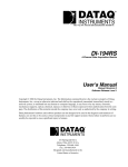
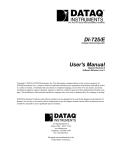
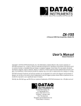
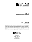
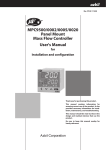
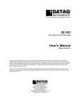
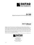
1
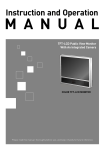
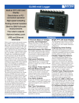
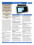
MT100 Paperless Chart Recorder and Data Logger
Desktop or panel mount
IP65 protects against dust
and moisture
5.7in. real-time color
display
10 analog input channels
(voltage, thermocouple,
RTD, and humidity)
4 logic/pulse inputs
4 relay alarm outputs
Records to USB memory
stick
Auto data archive via LAN
The MT100 is a feature-packed process
monitor for nearly any industrial application
to replace traditional chart and circular
recorders, digital and analog panel meters,
and other less capable monitoring equipment.
Its 10 isolated analog input channels are
complemented by four logic channels that
are programmable as either discrete or pulse
inputs. The 10 analog channels may be
programmed on a channel-by channel basis
to measure voltage from ±20mV to 50V full
scale across 12 ranges, thermocouple- or
RTD-based temperature, or 4-20 or 0-20 mA
current loops. Nearly all thermocouple types
are supported; along with both PT100 and
PT1000 RTDs. MT100 logic inputs detect
state changes, while pulse inputs may be
used for count and/or rate determinations. A
separate trigger input allows the instrument
to synchronize its measurements to external
events. The MT100 measures humidity
using either a built-in dry bulb/wet bulb
calculation, or by using an optional humidity
probe. All measurements are displayed in real
time on its built-in color display, and may be
simultaneously recorded to internal memory,
a standard removable USB memory stick,
or to a LAN-based file server. Each of four
alarm outputs with flexible trigger definitions
allow the MT100 to handle any alarm load up
to 250 VAC /2 A, meaning that the MT100
can directly control most lights or audible
alarms without external circuitry. If it’s
connected to a PC on its LAN connection it
can even send you an email during an alarm
event.
Features
Wide Voltage Measurement
Range
Bright TFT LCD Color Display
Full Electrical Isolation Per
Channel
Wide Sample Interval Selections
Each M100 analog channel can measure from
20 mV to 50 VFS across 12 programmable
measurement ranges.
Each analog M100 channel is electrically
isolated from all others and from instrument
ground to allow accurate and safe measurements in industrial applications where ground
potential differences are common.
Multiple Measurement Functions
Use the M100 to measure voltages, currents,
4/0-20 mA process current loops, thermocouple- and RTD-based temperatures and humidity.
Two Humidity measurement
modes
The M100 features a canned dry/wet bulb calculation for humidity measurements, or use the
optional B-530 humidity sensor.
Three Data Recording Modes
The MT100 creates a permanent record of recorded data in one of three ways: To its internal
12 MB memory; to a USB memory stick; to
a connected FTP file server over a LAN. File
sizes as large as 2GB are supported.
Four Discrete Inputs
The MT100 provides discrete input channels
that can be used for counting and rotational
speed measurement applications. Or program
the discrete inputs as simple logic level input
channels.
Four Alarm Outputs
Program the MT100 to trigger its alarm outputs
as a function of analog input signal level judgment, pulse judgment, or logic pattern. Built-in
relays on each channel simplify external wiring.
Alarms can be triggered from analog data based
on simple threshold, window in, window out,
and rate of change definitions.
The focal point of the MT100 is its built-in
5.7-inch color display that allows real time
trending, data review, and complete instrument
configuration.
Sample intervals can be programmed to be
one of eighteen values ranging from 100 ms
to one hour.
Engineering Units Scaling
Each MT100 channel allows up to four break
points to be programmed for accurate scaling
into meaningful units like psi, grams, newtons,
gallons per minute, etc.
Flexible Triggering Options
Allows data capture to be started or stopped
based upon signal level, an external event,
date/time, alarm, duration, or Boolean channel combinations. Analog signal triggers can
be programmed based upon level and window
tests: above threshold, below threshold, inside
window, or outside window.
Real Time and Post-recorded
Calculations
The MT100 may be programmed to calculate
average value, peak value, minimum value,
rms, and arithmetic operations (+,-,×,/) between
channels.
Built-in LAN and Web Server
The MT100 provides an Ethernet connection
that allows data file transfers, remote control,
real time monitoring, and email alarms.
Panel-mount or Optional Desktop Enclosure
The MT100 can be mounted to a panel using
included hardware, or purchase an optional
desktop enclosure with a carrying handle for
portable use.
DATAQ Instruments, Inc. • 241 Springside Drive • Akron, Ohio 44333 • Tel: 330-668-1444 • www.dataq.com
MT100 Major Components and Functions
Front panel and controls access
Operation status LED
POWER
START
Front panel
: ON when the power is ON
: ON during data cpture
Monitor
Control panel keys
Control panel cover
Control panel access
Behind the front panel
Front panel
Power switch
USB memory terminal
Rear panel view
Ethernet
USB terminal
Power terminal and
protective ground terminal
Power jack for
the humidity sensor
External input / output
LOGIC/PULSE
EXT TRIG
ALARM
: LOGIC/PULSE input
: Trigger input
: Alarm output
Analog signal input
terminals
330-668-1444
2
www.dataq.com
MT100 Signal I/O Connections
Analog inputs
Voltage Input
Thermocouple Input
Direct voltage
RTD Input
Current Input
Optional model R250
Ω
Ω
Analog input circuit per channel
+
......................................................... High -voltage terminal (terminal for high voltage signals)
-
......................................................... Low-voltage terminal (terminal for low-voltage input signals)
b
......................................................... Dedicated terminal when connection resistance temperature detector
*Resistance temperature detector input terminals A (+) and B (-) are isolated within each channel. Terminal b is shorted within
all channels.
Item
www.dataq.com
Description
Input configuration
Input configuration Isolated input, scanning
Analog voltage
20, 50, 100, 200, 500 mV/F.S.; 1, 2, 5, 10, 20, 50 V/F.S.; 1-5V
Thermocouples
Thermocouples K, J, E, T, R, S, B, N, W (WRe 5-26)
Resistance temperature detector
Pt100, JPt100, Pt1000 (IEC751)
A/D resolution
16-bit
Filter
Off, 2, 5, 10, 20, 40
Filter operation is on a moving average basis.
The average value of the set sampling count is used.
3
330-668-1444
MT100 Signal I/O Connections (continued)
Discrete inputs and outputs, and equivalent circuits
Connections for discrete inputs and outputs are made directly to the 20-terminal connection panel located at the back of
the MT100.
Typical pulse/logic input (4 each)
Item
External trigger input
Item
Description
Description
Number of input channels
4
Number of input channels
1
Input voltage range
0 to +24V max.
(single-ended ground input)
Input voltage range
0 to +24V max.
(single-ended ground input)
Threshold level
Approx. +2.5V
Threshold level
Approx. +2.5V
Hysteresis
Approx. 0.5 V (+2.5 to +3 V)
Hysteresis
Approx. 0.5 V (+2.5 to +3 V)
Typical alarm output (4 each)
Item
330-668-1444
Description
Number of output channels
4
Output format
Relay contact output (NO/NC)
<relay ratings>
contact rating : 250 VAC/2A, 30 VDC/2A
contact relay life : 100,000 operations
Withstand voltage
Between output and GND: 1000 VAC/1 minute
4
www.dataq.com
Connecting the MT100 to a PC
Connection using a USB cable
USB cable
Connection using a LAN
LAN cable
Use a crossover cable when
connecting directly to a PC
www.dataq.com
Use a straight cable when
connecting to a hub or switch
5
330-668-1444
The MT100’s Built-in Display
Using the vertical direction scrolling mode
Using the horizontal direction scrolling mode
(1) Data capture bar
Indicates capture time and remaining
capacity of the capturing media during
data capture.
(4) Waveform plot display (real time
display)
Displays measurement signals as waveforms in real time.
(2) Digital display
Displays the input value of each channel
in real time.
(3) Pen, trigger and alarm display
Displays the position of each channel signal with icons in real time. Also displays
the trigger level, position and direction
along with alarm thresholds.
(5) Compressed waveforms (historical
(6) Sampling interval display
display)
Displays the currently set sampling interDisplays compressed measurement signals val.
of historic data with an adjustable compression factor.
(7) File name display
Displays the name of the file currently being captured.
330-668-1444
6
www.dataq.com
Major Display Functions
The focal point for the MT100 during both setup and operation is its large, easy to see 5.7-in. full color display that can be
programmed to operate in a variety of ways to complement both your real time and post recording measurement needs.
Free running (real time)
Capturing (real time)
Dual view (real time & historic)
Replaying (historic)
Primarily used to set up the system to capture data. You can
view any input signal as a waveform or digital value.
Data is captured into the Internal memory or USB device.
Changing settings, except for some functions, using the
MENU key is disabled.
You can replay data during capture. Waveform displayed in After data capture to memory has ceased the display can be
the upper screen (right screen, when set to horizontal scroll) dedicated to reviewing previously recorded data.
is real time data, and the lower screen (left screen, when set
to horizontal scroll) is the previously recorded historic data.
www.dataq.com
7
330-668-1444
Major Display Functions (continued)
The MT100’s display can be further tailored to adapt to almost any measurement situation. You have control over the
number of displayed waveform zones, from one to 10. One zone displays up to ten MT100 channels overlapped; two
zones displays up to five channels per zone; five zones displays up to two channels per zone; ten zones displays up to ten
channels each in its own zone. Further, each channel’s waveform trace can be independently configured for color and trace
width, or disabled entirely. Finally, the display can be configured for a bar graph display to yield an entirely different look
and feel.
Waveform zones configured as 2 and 10
Typical waveform bar graph displays
User Event Markers Enhance Data Interpretation
With the MT100 you can register as many as eight unique text strings that describe possible events that may occur during
recording, and then trigger them during recording to permanently place one or more asynchronously during recording.
330-668-1444
8
www.dataq.com
Measurement Settings per Channel
The MT100 allows unequalled control over the how you acquire data. From allowing measurement function to be programmed per channel to the application of a moving average filter per channel, the MT100 lets you tailor its operation to
exactly what your application demands.
Typical menu screen
Analog and discrete settings overview
Items
Settings 1
Settings 2
Input
Range
Selections Available
Off, DC(Voltage), TEMP(Temperature), RH(Humidity)
DC
20, 50, 100, 200, 500 mV, 1, 2, 5, 10, 20, 50, 1-5 V
TEMP
TC-K, TC-J, TC-T, TC-R, TC-E, TC-B, TC-S, TC-N, TC-W, Pt100, JPt100, Pt1000
Filter
Off, 2, 5, 10, 20, 40
EU
Function
Off, ON
(Scaling settings)
Meas. Value (Upper/Lower)
enter numerical value
EU Value (Upper/Lower)
enter numerical value
Dec pt
1, 10, 100, 1000, 10000
Select
Length, Area, Volume, Velocity, Accel., Freq., Mass, Energy, Pressure, Flow, Temp
Choose
select
Unit
Misc.
enter text
CALC. Settings
Span settings
Logic/Pulse
CALC.
Off, ON, D/W (CH2 only, calculate with dry bulb CH1/wet bulb CH2)
Operation
CHn (+, -, ×, /) CHn
Scaling
/ 1000000, / 1000, x 1, x 1000, x 1000000
Upper/Lower
enter numerical value
Dec pt
1, 10, 100, 1000, 10000
Select
Length, Area, Volume, Velocity, Accel., Freq., Mass, Energy, Pressure, Flow, Temp
Choose
select
Unit
enter text
Upper/Lower
enter numerical value
Annotation string
enter text (max. 11 characters)
Perform Auto Zero ADJ.
► Execute
Reset Auto Zero ADJ.
► Execute
Logic/Pulse
Off, Logic, Pulse
Logic
Filter
Off, ON
Pulse
Input
Off, Revol., Counts, Inst.
Filter
Off, ON
Slope
EU
www.dataq.com
H, L
Function
Off, ON
Meas. Value
enter numerical value
EU Value
enter numerical value
Select
Length, Area, Volume, Velocity, Accel., Freq., Mass, Energy, Pressure, Flow, Temp
Choose
select
Unit
enter text
9
330-668-1444
Flexible Trigger Settings for Data Capture and Alarms
The MT100 can adapt to virtually any data recording condition, regardless of how unusual. Trigger conditions can be set
independently per channel, with Boolean AND and OR operations to combine multiple-channel triggers. Supported trigger
states include standard ±level thresholds as well as window definitions. Triggers can also be configured to set an alarm
state on any one of the MT100’s four alarm relay outputs.
Trigger settings overview
Items
Settings 1
Trigger Settings
Start Source
Settings 2
Off
Level
Selections Available
Off, Level, Alarm, Ext., Date, Weekly
None
Combination
OR, AND
Mode
Analog : Off, H, L, Win In, Win Out
Pulse : Off, H, L, Win In, Win Out
Logic : Off, H, L
Alarm
Level
set numeric value
Alarm port number
1, 2, 3, 4
External input
None
Date
Date, Time
Weekly
Weekly, Time
Stop Source
Off, Level, Alarm, Ext., Date, Weekly, Time
Off
Level
None
Combination
OR, AND
Mode
Analog : Off, H, L, Win In, Win Out
Pulse : Off, H, L, Win In, Win Out
Logic : Off, H, L
Alarm
Level
set numeric value
Alarm port number
1, 2, 3, 4
External input
None
Date
Date, Time
Weekly
Weekly, Time
Time
Repeat
Alarm Settings
330-668-1444
Alarm Level settings
1 s to 9999 h 59 min 59 s
Repeat
Off, ON
Repeat interval
1 min to 199 h 59 min
CH
CH1 to CH10, Pulse1 to Pulse4, LOGIC
Mode
Off, H, L, Win In, Win Out, RC
Level
set numeric value
Output
1, 2, 3, 4
Alarm Hold
On, Off
Send burnout alarm
On, Off
Data points of RC Alarm
1 to 32
10
www.dataq.com
Flexible Trigger Settings for Data Capture and Alarms
(continued)
MT100 trigger and alarm states
Trigger on positive threshold
Trigger (alarm) generated area
Trigger on negative threshold
Trigger (alarm) generated area
Measurement starts (alarm generated)
Measurement starts (alarm generated)
Set level
Set level
Trigger when inside window
Trigger (alarm) generated area
Trigger when outside window
Trigger (alarm) generated area
Measurement starts (alarm generated)
Measurement starts (alarm generated)
Set upper level
Set upper level
Set lower level
Set lower level
Alarm on rate of change
www.dataq.com
11
330-668-1444
Built-in Backup Processes Protect Data
The MT100 provides a built-in facility that allows the instrument to back up data recorded to its internal memory. You can
back up to either a standard USB memory stick inserted behind the MT100’s front panel, or to a local or remote FTP file
server over the MT100’s Ethernet interface. Data back up can be either disabled, or set to back up at pre-defined intervals
ranging from one to 24 hours.
Item
Description
Backup Intervals
Sets the interval to perform back up of captured data.
Off, 1, 2, 6, 12, 24 h
Backup Desination
Folder Name
Sets the location where back up data will be stored.†
USB1
Data is backed up in the USB memory.
This is enabled only when data is captured in the internal Flash memory.
FTP
Data is backed up in the FTP server in the network.
* FTP settings in the FILE menu is required.
Specifies the folder where data will be saved.
ex) \GRAPHTEC\TEST\20071204
Built-in Web Server
The MT100 features a built-in web server that allows you to access data and remotely control and configure the instrument from any local or remote location and from any standard Internet browser.
330-668-1444
12
www.dataq.com
Optional Desktop Enclosure
Mount the MT100 in an appropriately sized panel opening using the supplied hardware, or purchase the optional desktop
enclosure with handle for a more portable solution.
Handle
Support legs and stand
3.7
136.6
MT100 External Dimensions
144
25
150
3.7
144
136.6
172
200
Dimensional precision: ±5 mm
Unit: mm
www.dataq.com
13
330-668-1444
MT100 Specifications
Overall Specifications
Number of analog inputs: 1 unit (10 channels)
External input/output: Trigger input, Logic input 4 channels or Pulse
input 4 channels, Alarm output
PC interface: Ethernet (10BASE-T/100BASE-TX), USB (FullSpeed supported) provided as standard features
Internal memory devices: Internal memory: Approx. 14 MB
USB memory slot (FullSpeed supported) provided
as a standard feature.
Data backup functions: Setup conditions: EEPROM; Clock: Lithium
secondary battery
Clock accuracy (23°C ±0.002 % (approx. 50 seconds per month)
environment)
Operating Environment: 0 to 50°C, 5 to 85 % RH
Withstand voltage: Between each input channel and GND: 1 minute at
350 Vp-p; Between each input terminal: 1 minute
at 350 Vp-p; Between AC input and GND: 1
minute at 2000 VAC; Between alarm terminal and
GND: 1 minute at 1000 VAC
Insulation resistance: Between AC input and GND: 20M or higher
(500VDC); Between alarm terminal and GND:
50M or higher (500VDC); Between each input
channel and GND: 50M or higher (500VDC)
Power supply: AC input: 100 to 240 VAC/50 to 60 Hz
Terminal type: M4 screw type terminals
Power Consumption: AC Power consumption
No.
Condition
1
2
When the LCD is ON
When the screensaver is operating
Function Specifications
Display screen:
Note: Can be key-toggled
Sampling interval:
TIME/DIV:
EU (scaling function):
Bar graph display:
Review function:
Data save functions:
38VA
30VA
144 × 144 × 200 mm
2.1 kg
Protective class : IP65 compatible (surface panel
only); Vibration : Equivalent to automobile parts
Type 1 Category A classification
Wet and dry bulb conversion:
Memory capacity: Internal memory : Approx. 14 MB Flash Memory
USB memory : Max 2 GB (depends on the type of
USB memory used)
Memory contents: Setup conditions, measured data, screen copy
PC Interface
Calculation types: Addition, subtraction, multiplication, division
Input : Analog ch 1 to 10
Function: Converts dry bulb or wet bulb temperature to humidity
Dry bulb: 1 ch fixed (input temperature, outputs
temperature)
Wet bulb: 2 ch fixed (input wet bulb temperature,
calculates humidity with 1 ch; temperature. Outputs
humidity.)
Measurement range : 0 to 100 % RH.
Note: Some dry bulb or wet bulb temperatures may not be
calculated.
Interface types: Ethernet (10BASE-T/100BASE-TX)
USB (FullSpeed)
Software functions: Data transfer to the PC (realtime, memory)
PC control of the MT100
Ethernet functions: Web server function : Displays MT100’s screen
(10BASE-T/100BASE-TX) image on Web browser, operation of MT100
FTP server function : Transfers and deletes files
from internal memory and USB memory
FTP client function : Supports backup of data
ininternal memory and USB memory
NTP client function : Adjusts internal clock
USB functions: USB drive mode : Transfers and deletes files from
internal memory
Realtime data transfer 100 msec/10 ch maximum
speed:
Search functions:
Annotation input function:
Message/marker function:
Function: Search the captured data for the required
number of points
Search type : Channel, Pulse, Logic, Level, Alarm
search
Function: A comment can be input for each channel
Inputtable characters: Alphanumerics
Number of characters : 11 (displayed up to 8 characters)
Function : Records message/marker at the specified
timing
Number of registered messages: 8
Markers: Start/stop, trigger, alarm, power failure
Messages: Input arbitrary messages before capture
Trigger Functions
Monitor
Display: 5.7-inch TFT color LCD (QVGA: 320 x 240 dots)
Displayed languages: Japanese, English, Others
Backlight life: 40,000 hrs (when brightness is down to 50 %),
depends on operation environment
Backlight: Screen saver function (10, 30 sec; 1, 2, 5, 10, 30,
60 min.); Off during operation, resumed by key
operation and alarm
330-668-1444
Types of statistical calculation: Average value, peak
value, maximum value, minimum value, RM
Number of operations : Maximum of 2 can be set
simultaneously
Method : Realtime and between cursors specified
(during data replay)
Note: Realtime calculation results are displayed in Digital
screen + Calculation Display screen.
Calculation between
channels:
Internal Memory Devices
100 ms/10 ch maximum
100, 125, 200, 250, 500 ms; 1, 2, 5, 10, 20, 30 sec;
1, 2, 5, 10, 20, 30 min; 1 h
1, 2, 5, 10, 20, 30 sec/DIV; 1, 2, 5, 10, 20, 30 min/
DIV; 1, 2, 5, 10, 12, 24, 72 h/DIV
4 points can be set for each channel
Display direction: Vertical, 10 ch + pulse 4 ch
Reference position: Bottom or center
Scale divided into: 10 (fixed)
Data replay during data capture
Capture to internal memory; Capture to USB
memory; Setup data can be saved (to internal or
USB memory); Copy of data screen can be saved
(to internal or USB memory); Back up function (internal memory -> USB memory, internal memory
-> PC*1, USB memory -> PC*1); File name increment feature.
Note: USB memory can be removed during data capture.
Statistical calculation:
Note: normal status is when LCD brightness is set to MAX
External Dimensions:
Weight:
Vibration-tested
conditions:
Waveform screen + Digital screen (vertical, horizontal), Digital screen + Calculation
Display screen, Bar Graph screen (vertical)
14
Repeat Trigger: Off, On
Trigger types: Start: Data capture starts when a trigger is generated
Stop : Data capture stops when a trigger is generated
Trigger settings: Start: Off, Level, Alarm, External, Date, Weekly
Stop: Off, Level, Alarm, External, Date, Weekly, Time
Trigger judgment modes: Analog: H, L, Window In, Window Out
Logic: H, L
Pulse: H, L, Window In, Window Out
www.dataq.com
MT100 Specifications (continued)
External Input/Output Functions
Input/output types:
Input Unit Specifications
Number of input channels:
Input terminal type:
Input method:
• Trigger input (1 ch)
• Logic input (4 ch) or Pulse input (4 ch)
• Alarm output (4 ch)
*Switch between Logic and Pulse
Input specifications:
Terminal type : M4 screw type terminals
Maximum input voltage : 0 to 24 V (single-ended
ground input)
Input threshold voltage : Approx. 2.5 V
Hysteresis : Approx. 0.5 V (+ 2.5 to + 3 V)
Alarm output specifica- Output format : Relay contact output (NO/NC)
tions: Terminal type : M4 screw type terminals
Rated : 250 VAC/2A
Output conditions : Level judgment, window judgment, logic pattern judgment,
pulse judgment, rate of change judgement
*Set output conditions of four channel values.
Pulse input: Revolutions mode (engines, etc.)
Function : Counts the number of pulses per second; enables them to be converted to rpms
Span : 50, 500, 5000, 50 k, 500 k, 5 M, 50 M, 500
M RPM/F.S.
Counts mode (electric meters, etc.)
Function: Displays a count of the number of pulses
for each sampling interval from
the start of measurement
Span : 50, 500, 5000, 50 k, 500 k, 5 M, 50 M, 500
M C/F.S.
Inst. Mode
Function: Counts the number of pulses for each
sampling interval
Resets the count value after each sampling interval
Span : 50, 500, 5000, 50 k, 500 k, 5 M, 50 M, 500
M C/F.S.
Maximum number of pulse input
Counts, Inst. Modes : 50 k/sampling interval
Revolution counts mode : 50 k/s
Scan speed:
Measurement ranges:
Measurement accuracy*
Voltage:
Temperature
(Thermocouple):
Resistance Temperature
Detector:
0.1% of Full Scale
Measurement Temperature
Measurement
Range (°C)
Accuracy (°C)
0 ≤ Ts ≤ 100
±5.2
100 < Ts ≤ 300
±3.0
R/S
R: 300 < Ts ≤ 1600
±(0.05% of rdg +2.0)
S: 300 < Ts ≤ 1760
±(0.05% of rdg +2.0)
400 ≤ Ts ≤ 600
±3.5
B
600 < Ts ≤ 1820
±(0.05% of rdg +2.0)
-200 ≤ Ts ≤ -100
±(0.05% of rdg +2.0)
K
-100 < Ts ≤ 1370
±(0.05% of rdg +1.0)
-200 ≤ Ts ≤ -100
±(0.05% of rdg +2.0)
E
-100 < Ts ≤ 800
±(0.05% of rdg +1.0)
-200 ≤ Ts ≤ -100
±(0.1% of rdg +1.5)
T
-100 < Ts ≤ 400
±(0.1% of rdg +0.5)
-200 ≤ Ts ≤ -100
±2.7
J
-100 < Ts ≤ 100
±1.7
100 < Ts ≤ 1100
±(0.05% of rdg +1.0)
N
0 ≤ Ts ≤ 1300
±(0.1% of rdg +1.0)
W
0 ≤ Ts ≤ 2000
±(0.1% of rdg +1.5)
Reference contact compensation accuracy: ±0.5°C
Thermocouple diameters T: 0.32 φ, others: 0.65 φ
TC
Type
Pt100
Jpt100
Control Software
Compatible operating Windows 2000, XP, Vista (32-bit version, 64-bit
system: version)
Functions: Main unit control, realtime data capture, data
conversion
Allowed connection: Up to 10
Number of channels per 10 ch maximum
connection:
Maximum number of 100 ch maximum
channels:
Settings: AMP settings, data settings, trigger/alarm settings,
report settings, others
Captured data: Realtime data (CSV, Binary)
Memory data (CSV, Binary)
USB memory data (CSV, Binary)
Display: Analog waveforms, logic waveforms, pulse waveforms, digital values
Display modes: Y-T View, X-Y View, Digital View, Meter View,
Report View
File conversion: Between cursors, All data
Monitor functions: Alarm monitor enables sending of email to the specified address
Dual-screen function: Displays the current data alongside past data
Statistic/History: Displays maximum, minimum, and average values
during measurement
Report function: Enables creation of daily or monthly files
www.dataq.com
10 channels
M4 screw type terminals
Photo MOS relay scanning system
All channels isolated, balanced input
0.1s/10 ch maximum
Voltage: 20, 50, 100, 200, 500 mV; 1, 2, 5, 10, 20,
50 V; 1-5 V F.S.
Temperature: Thermocouples: K, J, E, T, R, S, B,
N, W (WRe5-26); Resistance temperature detector:
Pt100, JPt100, Pt1000 (IEC751)
Humidity: 0 to 100% (voltage 0 V to 1 V scaling
conversion) *with B-530 (option)
15
Measurement Temperature Range (°C)
-200 to 850
(FS=1050)
Applied
Current
-200 to 500 (FS=700)
1mA
Pt1000 -200 to 500 (FS=700)
1mA
0.2mA
Measurement
Accuracy (°C)
±(0.05% of rdg
+0,5°C)
±(0.05% of rdg
+0,5°C)
±(0.05% of rdg
+0,5°C)
* 23°C ±3°C when 30 minutes have elapsed after the power was switched on (filter On (10),
1 s/20 ch sampling, GND connected).
Reference contact
compensation accuracy:
A/D converter:
Temperature coefficient:
Input resistance:
Allowable signal source
resistance:
Maximum permissible
input voltage:
Withstand voltage:
Insulation resistance:
Common mode rejection
ratio:
Noise:
Filter:
Internal/External switching
16 bits (out of which 14 bits are internally acknowledged)
Gain: 0.01% of F.S./ °C
1 MΩ ±5%
Within 300 Ω
Between +/– terminals : 60 Vp-p
Between input terminal/input terminal : 60 Vp-p
Between input terminal/GND : 60 Vp-p
Between input terminal/input terminal : 1 minute at
350 Vp-p
Between input terminal/GND : 1 minute at 350 Vp-p
Between input terminal/GND : At least 50MΩ (at
500 VDC)
At least 90 dB (50/60 Hz; signal source 300 Ω or
less)
At least 48 dB (with +/– terminals shorted)
Off, 2, 5, 10, 20, 40
Filter operation is on a moving average basis.
The average value of the set sampling count is
used.
330-668-1444
MT100 Included and Optional Accessories
Included Accessories
Item
Description
Quantity
Quick Start Guide
MT100-UM-8xx
1
CD-ROM
MT100-CDM0xM (User Manual, Application software)
1
Panel mount bracket
1 set includes two brackets
2
Optional Desktop Case model B-541
Item
Description
Contents
Desktop case, power cable (corresponding to area), instruction manual, screws (4)
Power supply cord rating and length
UL : 125 V/10 A Approx. 1.8 m U suffix
Optional Humidity Sensor model B-530
Item
Description
Alowable temperature range
-25 to 80°C
Allowable Humidity Range
0 to 100%
Relative humidity measurement accuracy
±3% RH (5 to 98% RH at 25°C)
Method
Capacitance method
Relative humidity measurement accuracy
5 to 98%
0 to 10°C (±5%RH); 10 to 20°C (±4%RH); 20 to 30°C (±3%RH); 30 to 40°C (±4%RH);
40 to 50°C (±5%RH); 50 to 60°C (±6%RH); 60 to 70°C (±7%RH); 70 to 80°C (±8%RH)
Response time
15 s (90% response when membrane filter installed)
Sensor output
0 to 1 VDC
Sensor power source
5 to 16 VDC
Power consumption
approx. 4mA
External dimensions
14mm × 80 mm (excluding cable)
Cable length
3m
Ordering Guide
Description
Order No.
Description
Order No.
Desktop Case
MT100
Paperless chart recorder and data logger with 10
isoloated analog inputs that can be programmed
on a channel-by channel basis to measure voltage
from ±20mV to 50V full scale across 12 ranges,
thermocouple- or RTD-based temperature, or 4-20
or 0-20 mA current loops.
Portable desktop enclosure with handle for
portability.
MT100
Humidity Sensor
3-meter with dedicated power connector.
Resistor
Precision 250 Ω resistor, 0.1%
DATAQ Instruments, Inc.
241 Springside Drive
Akron, Ohio 44333
Phone: 330-668-1444
Fax: 330-666-5434
Data Acquisition Product Links
(click on text to jump to page)
Data Acquisition | Data Logger | Chart Recorder
DATAQ, the DATAQ logo and WinDaq are registered trademarks of DATAQ Instruments, Inc. All rights reserved. Copyright © 2011 DATAQ Instruments, Inc.
The information on this data sheet is subject to change without notice.
B-541
B-530
R250