1
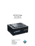
ANT130 Series Stage
User’s Manual
P/N: EDS145 (Revision 1.03.00)
Dedicated to the Science of Motion
Aerotech, Inc.
101 Zeta Drive,
Pittsburgh, PA, 15238
Phone: 412-963-7470
Fax: 412-963-7459
www.aerotech.com
Technical Support
Aerotech provides downloadable resources (such as up-to-date software, product manuals, and Help files),
training schedules, and PC-to-PC remote technical support. You can also complete Product Return (RMA)
forms and get information about repairs and spare or replacement parts.
Go to http://www.aerotech.com/cussv.html for information and support about your Aerotech products.
For immediate help, contact a service office (listed below) or your sales representative.
United States (World Headquarters)
Phone: (412) 967-6440
Fax: (412) 967-6870
Email: [email protected]
Japan
Phone: +81(0)47-489-1742
Fax: +81(0)47-489-1743
Email: [email protected]
United Kingdom
Phone: +44 118 940 9400
Fax: +44 118 940 9401
Email: [email protected]
China
Phone: +852-3793-3488
Email: [email protected]
Germany
Phone: +49 911 967 9370
Fax: +49 911 967 93720
Email: [email protected]
Taiwan
Phone: +886 (0)2-8502-6651
Email: [email protected]
N O T E : Aerotech continually improves its product offerings; listed options may be superseded at any
time. Refer to the most recent edition of the Aerotech Motion Control Product Guide for the most current
product information at www.aerotech.com.
N O T E : All drawings and illustrations are for reference only and were complete and accurate as of this
manual’s release. The most recent system drawings and schematics can be found on your software CD
ROM or on www.aerotech.com.
N O T E : This manual and any additional instructions included with the ANT130 should be read in their
entirety before operating the ANT130 .
N O T E : This product is intended for light industrial manufacturing or laboratory use.
Revision History
1.03.00
January 30, 2012
1.02.00
November 5, 2010
1.01.00
April 23, 2010
1.00.00
November 18, 2009
Product names mentioned herein are used for identification purposes only and may be trademarks of
their respective companies.
Copyright © 2009 - 2012. Aerotech, Inc. All Rights Reserved.
ANT130 Series Stage User's Manual
Table of Contents
Table of Contents
Table of Contents
List of Figures
List of Tables
iii
v
vii
Chapter 1: Overview
1
1.1. Standard Features
1.1.1. Optional Features
1.1.2. Model Numbers
1.2. Dimensions
1.3. Safety Procedures and Warnings
1.4. EC Declaration of Incorporation
Chapter 2: Installation
2.1. Unpacking and Handling the Stage
2.2. Shipping Brackets
2.3. Preparing the Mounting Surface
2.4. Securing the Stage to the Mounting Surface
2.5. Attaching the Payload to the Stage
2.6. Electrical Installation
2
2
3
4
7
8
9
9
10
13
14
15
16
Chapter 3: Operating Specifications
17
3.1. Environmental Specifications
3.2. Accuracy and Temperature Effects
3.3. Basic Specifications
3.4. Load Capability
3.5. Limit Switches
3.5.1. Limit Switch Wiring
3.6. Standard Motor Wiring
3.7. Vacuum Operation
3.7.1. Special Guidelines
17
18
19
24
29
29
30
34
34
Chapter 4: Maintenance
4.1. Service and Inspection Schedule
4.2. Cleaning and Lubrication
4.2.1. Recommended Cleaning Solvents
4.2.2. Important Notes on Lubrication
4.2.3. Lubrication and Cleaning Process
Chapter 5: ANT130-L-Z
5.1. Standard Features
5.1.1. Model Numbers
5.2. Dimensions
5.3. Basic Specifications
5.4. Z-Axis Installation
5.4.1. Securing the Stage to the Mounting Surface
5.4.2. Attaching the Payload to the Stage
35
35
36
36
36
36
37
37
39
40
41
42
42
44
Appendix A: Warranty and Field Service
45
Appendix B: Technical Changes
47
Index
49
Reader's Comments
51
www.aerotech.com
iii
Table of Contents
iv
ANT130 Series Stage User's Manual
www.aerotech.com
ANT130 Series Stage User's Manual
List Of Figures
List of Figures
Figure 1-1:
Figure 1-2:
Figure 1-3:
Figure 1-4:
Figure 2-1:
Figure 2-2:
Figure 2-3:
Figure 2-4:
Figure 2-5:
Figure 2-6:
Figure 2-7:
Figure 3-1:
Figure 3-2:
Figure 3-3:
Figure 3-4:
Figure 3-5:
Figure 3-6:
Figure 3-7:
Figure 3-8:
Figure 3-9:
Figure 3-10:
Figure 3-11:
Figure 5-1:
Figure 5-2:
Figure 5-3:
Figure 5-4:
ANT130-L (left) and ANT130-XY (right) Linear Positioning Stage
ANT130-L Dimensions
ANT130-XY Dimensions
ANT130-XY CMS Dimensions
Shipping Bracket Used on Single Axis Stages
Shipping Brackets Used on XY Systems
ANT130-XY Shipping Bracket Removal Procedure (Step 1)
ANT130-XY Shipping Bracket Removal Procedure (Step 2)
ANT130-XY Shipping Bracket Removal Procedure (Step 3)
Mounting to a Flat Surface
Mounting Hole Locations
Stage Loading Conditions
Load Capability of ANT130-035-L Stages
Load Capability of ANT130-060-L Stages
Load Capability of ANT130-110-L Stages
Load Capability of ANT130-160-L Stages
Load Capability of ANT130-060-XY Stages
Load Capability of ANT130-110-XY Stages
Load Capability of ANT130-160-XY Stages
ANT130 Series Limit Switch Wiring
Motor Wiring Connector for Optional 4 pin Hi-Power D Connector (-4DU-25DU Option)
Encoder Connector with Optional 4 pin Hi-Power D Connector (-4DU-25DV Option)
Typical ANT130L-Z Series Positioning Stage
ANT130L-Z with Component Labeling
ANT130-L-Z Dimensions
ANT130L-Z Mounting Pattern
www.aerotech.com
1
4
5
6
10
10
11
11
12
13
14
24
25
25
26
26
27
27
28
29
32
32
37
38
40
42
v
List of Figures
vi
ANT130 Series Stage User's Manual
www.aerotech.com
ANT130 Series Stage User's Manual
List of Tables
List of Tables
Table 1-1:
Table 1-2:
Table 3-1:
Table 3-2:
Table 3-3:
Table 3-4:
Table 3-5:
Table 3-6:
Table 5-1:
Table 5-2:
Table B-1:
Table B-2:
Model Numbering System for Single Axis Stage
Model Numbering System for Two Axis XY Stage
Environmental Specifications
ANT130-L Series Specifications
ANT130-XY Series Specifications
BLMUC-95-A Motor Specifications
Feedback and Motor Pin Assignments for -25DU Cable Option
Motor and Feedback Wiring Pinout Descriptions
Model Numbering System
ANT130L-Z Series Specifications
Current Changes (1.03.00)
Archived Changes
www.aerotech.com
3
3
17
19
21
23
31
33
39
41
47
48
vii
List of Tables
viii
ANT130 Series Stage User's Manual
www.aerotech.com
ANT130 Series Stage User's Manual
Overview
Chapter 1: Overview
The ANT130-L and ANT130-XY series stages offer excellent performance in speed, accuracy, resolution,
repeatability, reliability, travel range, and are offered in two accuracy grades. With its low profile and outstanding performance characteristics, the ANT130 stages are the ultimate solution for high-accuracy alignment, inspection, positioning, and measurement stations.
Figure 1-1:
www.aerotech.com
ANT130-L (left) and ANT130-XY (right) Linear Positioning Stage
Chapter 1
1
Overview
ANT130 Series Stage User's Manual
1.1. Standard Features
The ANT130 series stages incorporate linear cross-roller bearings, a linear motor, and a non-contact linear
encoder. These features allow the ANT130 series stages to provide excellent performance in speed, accuracy, resolution, repeatability, and reliability.
The linear cross-roller bearings offer excellent stiffness, high load carrying capabilities, and minimal friction
for smooth movement. The cross roller bearings also incorporate a system to prevent cage creep and keep
the rollers centered in the bearing rails.
The ANT130 series stages are driven by a linear motor. The brushless linear motor uses an ironless forcer,
which means there is zero cogging and there are no attractive forces – resulting in unsurpassed smoothness
of motion. A moving magnet track design eliminates the need for cable management, improving long-term
reliability.
A high-accuracy, non-contact linear encoder allows the ANT130 series stages to have an incremental step
size of 1 nm when coupled with Aerotech drives and controls. This is especially useful in alignment applications, where outstanding step-to-step resolution is critical.
The single axis, linear ANT130 has four standard travel distances: 35mm, 60mm, 110mm, and 160mm. The
two-axis X-Y ANT130 offers three standard travel distance combinations: 60mm x 60mm, 110mm x 110mm,
and 160mm x 160mm.
Optical limit switches are mounted at each end of travel. These switches are configured as normally-closed.
If the stage is driven beyond these electrical limits, a mechanical, shock absorbing hard stop limits carriage
movement.
1.1.1. Optional Features
ANT130 stages can be ordered as a single axis, ANT130-L, or as and integrated X-Y stage, ANT130-XY.
The ANT130 stages also have the option of two accuracy grades. There is the standard ANT130 stage accuracy, or the high accuracy grade (“-PLUS” designation) ANT130 stage.
ANT130 stages come standard with a single, 25-pin D connector (per axis), however there is the option to
have a 4-pin hi-power D and 25-pin D connector for applications that require bus voltages greater than 80 V.
For vacuum applications, two vacuum preparation options are available; one compatible with low vacuum
environments (down to 10-3 torr) and the other for high vacuum (10-3 to 10-6 torr). Custom configurations,
such as XY-Z systems are common and readily available. Contact Aerotech for more details on optional features and configurations.
2
Chapter 1
www.aerotech.com
ANT130 Series Stage User's Manual
Overview
1.1.2. Model Numbers
Stage model number example: ANT130-110-L-PLUS-25DU
The tables below list the available options in the order they appear in the example above. Aerotech continually improves its product offerings, and listed options may be superseded at any time. Refer to the most
recent edition of the Aerotech Motion Control Product Guide for the most current product information at
www.aerotech.com.
Table 1-1:
Model Numbering System for Single Axis Stage
ANT130-L Series Linear Motor Stage
ANT130-035-L
ANT130-035-L-PLUS
ANT130-060-L
ANT130-060-L-PLUS
ANT130-110-L
ANT130-110-L-PLUS
ANT130-160-L
ANT130-160-L-PLUS
35 mm travel stage with linear motor and limits
35 mm travel stage with linear motor and limits, high accuracy
60 mm travel stage with linear motor and limits
60 mm travel stage with linear motor and limits, high accuracy
110 mm travel stage with linear motor and limits
110 mm travel stage with linear motor and limits, high accuracy
160 mm travel stage with linear motor and limits
160 mm travel stage with linear motor and limits, high accuracy
Output Cable Connectors
-25DU
Single 25-pin D connector (standard)
-4DU-25DU
4-pin HPD and 25-pin D connectors
Note: -25DU single 25-pin connector option not valid for systems using bus voltages greater than 80 V
Table 1-2:
Model Numbering System for Two Axis XY Stage
ANT130-XY Series Linear Motor Stage
ANT130-060-XY
ANT130-060-XY-PLUS
ANT130-110-XY
ANT130-110-XY-PLUS
ANT130-160-XY
ANT130-160-XY-PLUS
60 mm travel stage with linear motor and limits
60 mm travel stage with linear motor and limits, high accuracy
110 mm travel stage with linear motor and limits
110 mm travel stage with linear motor and limits, high accuracy
160 mm travel stage with linear motor and limits
160 mm travel stage with linear motor and limits, high accuracy
Cable Management System Options
-XY-CMS
CMS Cable management system for X-Y assembly
-XYZ-CMS
Cable management system for 3-axis assembly (XY stage plus additional
axis on top)
Output Cable Connectors
-25DU
Single 25-pin D connector (standard)
-4DU-25DU
4-pin HPD and 25-pin D connectors
Note: -25DU single 25-pin connector option not valid for systems using bus voltages greater than 80 V
www.aerotech.com
Chapter 1
3
Overview
ANT130 Series Stage User's Manual
1.2. Dimensions
Figure 1-2:
4
ANT130-L Dimensions
Chapter 1
www.aerotech.com
ANT130 Series Stage User's Manual
Overview
RAD. F
CABLE BEND RADIUS
25
Ø12.7
D/2
21X M61.0 7.0
CENTER ON
CARRIAGE
C/2
25
50
Ø6.8
75
120
8
DETAIL A
SCALE 2 : 5
MOUNTING HOLE TYP.
B/2
D/2
50
75
B/2
90
C/2
D/2
125
D/2
MODEL
A = STAGE
LENGTH
B = NOMINAL
TRAVEL
C = LIMIT
TRAVEL
D = HARDSTOP
TRAVEL
E
F
ANT130-060-XY
180
60 X 60
66 X 66
75 X 75
42
~87.5
ANT130-110-XY
230
110 X 110
116 X 116
125 X 125
67
~100
ANT130-160-XY
280
160 X 160
166 X 166
175 X 175
92
~112.5
130
A
85
A
E
120
1
90
200
130
A
DIMENSIONS: MILLIMETERS
1
ANT130-110-XY AND ANT130-160-XY ONLY
Figure 1-3:
www.aerotech.com
ANT130-XY Dimensions
Chapter 1
5
Overview
ANT130 Series Stage User's Manual
±45°
CENTER POST
ADJUSTMENT
82.6 SQ
50 SQ
AIR FITTING FOR
Ø4 [Ø5/32”] VACUUM
LINE (ALTERNATE
ATTACHMENT METHOD)
4X Ø6.8 SLOT THRU ALL
Ø11.0 SLOT 8.0
50.8 SQ
38.1
CABLE TIE MOUNTS
(BOTH SIDES)
130.2
38.1
38.1
82.6
44.4
34.9
25.4
ACP3: INCLUDED WITH -XYZ-CMS OPTION
11.8
11.1 REF
NOTE:
[QTY 4] MAGNETS
(ALTERNATE ATTACHMENT
METHOD)
ACP2: INCLUDED WITH -XY-CMS OPTION
Figure 1-4:
6
DIMENSIONS NOT SHOWN
ARE THE SAME AS ACP2
DIMENSIONS: MILLIMETERS
ANT130-XY CMS Dimensions
Chapter 1
www.aerotech.com
ANT130 Series Stage User's Manual
Overview
1.3. Safety Procedures and Warnings
The following statements apply wherever the Warning or Danger symbol appears within this manual. Failure
to observe these precautions could result in serious injury to those individuals performing the procedures
and/or damage to the equipment. Operators should be trained before operating this equipment.
D A N G E R : To minimize the possibility of electrical shock and bodily injury or death, disconnect all electrical power prior to making any electrical connections.
D A N G E R : To minimize the possibility of electrical shock and bodily injury or death when any
electrical circuit is in use, ensure that no person comes in contact with the circuitry when the
ANT130 is connected to a power source.
D A N G E R : To minimize the possibility of bodily injury or death, disconnect all electrical power
prior to making any mechanical adjustments.
D A N G E R : Moving parts of the ANT130 can cause crushing or shearing injuries. All personnel
must remain clear of any moving parts.
W A R N I N G : If the ANT130 is used in a manner not specified by the manufacturer, the protection provided by the ANT130 can be impaired and result in damage, shock, injury or death.
W A R N I N G : Cables can pose a tripping hazard. Securely mount and position all ANT130
cables to avoid potential hazards.
W A R N I N G : Do not expose the ANT130 to environments or conditions outside the specified
range of operating environments. Operation in conditions other than those specified can cause
damage to the equipment.
W A R N I N G : The ANT130 must be mounted securely. Improper mounting can result in injury
and damage to the equipment.
W A R N I N G : Use care when moving the ANT130. Manually lifting or transporting the ANT130
can result in injury.
W A R N I N G : Only trained personnel should operate, inspect, and maintain the ANT130.
W A R N I N G : This ANT130 is intended for light industrial manufacturing or laboratory use. Use
of the ANT130 for unintended applications can result in injury and damage to the equipment.
W A R N I N G : Before using this ANT130, perform an operator risk assessment to determine
the needed safety requirements.
www.aerotech.com
Chapter 1
7
Overview
ANT130 Series Stage User's Manual
1.4. EC Declaration of Incorporation
Manufacturer:
Aerotech, Inc.
101 Zeta Drive
Pittsburgh, PA 15238
USA
herewith declares that the product:
Aerotech, Inc. ANT130 Stage
is intended to be incorporated into machinery to constitute machinery covered by the Directive
2006/42/EC as amended;
does therefore not in every respect comply with the provisions of this directive;
and that the following harmonized European standards have been applied:
EN ISO 12100-1,-2:2003+A1:2009
Safety of machinery - Basic concepts, general principles for design
ISO 14121-1:2007
Safety of machinery - Risk assessment - Part 1: Principles
EN 60204-1:2005
Safety of machinery - Electrical equipment of machines - Part 1: General requirements
and further more declares that
it is not allowed to put the equipment into service until the machinery into which it
is to be incorporated or of which it is to be a component has been found and
declared to be in conformity with the provisions of the Directive 2006/42/EC and
with national implementing legislation, i.e. as a whole, including the equipment
referred to in this Declaration.
Authorized Representative:
Address:
Name
Position
Location
Date
8
Manfred Besold
AEROTECH GmbH
Süd-West-Park 90
D-90449 Nürnberg
/ Alex Weibel
Engineer Verifying Compliance
Pittsburgh, PA
September 2010
Chapter 1
www.aerotech.com
ANT130 Series Stage User's Manual
Installation
Chapter 2: Installation
This chapter describes the installation procedure for the ANT130 stage, including handling the stage, preparing the mounting surface to accept the stage, securing the stage to the mounting surface, attaching the
payload, and making the electrical connections.
W A R N I N G : Installation must follow the instructions in this chapter. Failure to follow these
instructions could result in injury and damage to the equipment.
2.1. Unpacking and Handling the Stage
Carefully remove the stage from the protective shipping container. Use compressed nitrogen or clean, dry air
to remove any dust or debris that has collected during shipping. Visually inspect the stage for damage. If any
damage has occurred during shipping report it immediately. Remove stage shipping brackets. Set the stage
on a smooth, flat, and clean surface. This is a simple, yet very important step in maintaining the integrity of
the stage.
Each stage has a label listing the system part number and serial number. These numbers contain information
necessary for maintaining or updating system hardware and software. Locate this label and record the information for later reference.
W A R N I N G : Improper handling could adversely affect the ANT130’s performance. Use care
when moving the stage. Manually lifting or transporting the stage can result in injury.
W A R N I N G : Lift the ANT130 only by the base.
www.aerotech.com
Chapter 2
9
Installation
ANT130 Series Stage User's Manual
2.2. Shipping Brackets
Aerotech provides shipping brackets to prevent unwanted stage motion and potential damage from occurring
during shipment. The brackets are red anodized aluminum, and they must be removed from the stage before
it can operate. There are two types of shipping brackets: one type for the linear stages (ANT130-L) and one
type for the integrated XY stages (ANT130-XY). Figure 2-1 shows the shipping brackets used to constrain
single axis stages. Figure 2-2 shows the shipping brackets used to constrain XY systems. Figure 2-3, Figure
2-4, and Figure 2-5 show how to properly remove the shipping brackets used on XY systems.
Figure 2-1:
Figure 2-2:
10
Shipping Bracket Used on Single Axis Stages
Shipping Brackets Used on XY Systems
Chapter 2
www.aerotech.com
ANT130 Series Stage User's Manual
Installation
Figure 2-3:
ANT130-XY Shipping Bracket Removal Procedure (Step 1)
Figure 2-4:
ANT130-XY Shipping Bracket Removal Procedure (Step 2)
www.aerotech.com
Chapter 2
11
Installation
ANT130 Series Stage User's Manual
Figure 2-5:
ANT130-XY Shipping Bracket Removal Procedure (Step 3)
N O T E : After removing the lifting features or shipping brackets, retain them for future use. In the event that
the product requires service at the factory, the lifting features or shipping brackets should be reattached to
ensure that the ANT130 ships safely.
12
Chapter 2
www.aerotech.com
ANT130 Series Stage User's Manual
Installation
2.3. Preparing the Mounting Surface
The mounting surface should be flat to 5 μm and have adequate stiffness in order to achieve the maximum
performance from the ANT130. When an ANT130 series stage is mounted to a warped surface, the stage can
be distorted as the mounting screws are tightened (see Figure 2-6). Any distortion will decrease the overall
accuracy of the stage. Adjustments to the mounting surface must be done before the stage is secured.
Figure 2-6:
Mounting to a Flat Surface
N O T E : To maintain accuracy, the mounting surface should be flat within 5 µm .
N O T E : The ANT130 base is precision machined and verified for flatness prior to product assembly at the
factory. If machining is required to achieve the desired flatness, it should be performed on the mounting surface rather than the ANT130 base. Shimming should be avoided if possible. If shimming is required, it
should be minimized to improve the rigidity of the system.
www.aerotech.com
Chapter 2
13
Installation
ANT130 Series Stage User's Manual
2.4. Securing the Stage to the Mounting Surface
Move the stage table to access the 6.8 mm (0.27 in) diameter mounting holes along the edges of the stage.
This stage is designed to use socket head cap screws (SHCS) to secure the base to the mounting surface.
Use M6 x 18 mm or 1/4 x 3/4" long SHCS to achieve 1.5x diameter thread engagement. Torque the mounting
screws to 5.4 N*m (4 ft*lb).
W A R N I N G : The ANT130 must be mounted securely. Improper mounting can result in injury
and damage to the equipment.
W A R N I N G : Do not attempt to manually move the ANT130 if it is connected to a power
source.
Figure 2-7:
14
Mounting Hole Locations
Chapter 2
www.aerotech.com
ANT130 Series Stage User's Manual
Installation
2.5. Attaching the Payload to the Stage
To prevent damage to the stage or parts, test the operation of the stage before any payload is mounted to the
stage tabletop. Proceed with the electrical installation and test the motion control system in accordance with
the system documentation. Document all results for future reference. For information on electrical connections, refer to the Electrical Installation section later in this chapter, the documentation of the motion control system delivered with the stage, and the wiring drawings in Chapter 3: Operating Specifications.
N O T E : For valid system performance, the mounting interface should be flat within 1 µm per 50 mm.
The payload should be flat, rigid, and comparable to the stage in quality.
Refer to Section 3.4. for information on cantilevered loads and load positioning.
N O T E : Do not attach a payload to the stage table with screws that are too long. A screw passing through
the stage table can come into contact with internal parts, affecting travel and possibly damaging the stage.
Mounting screws should not project more than 7 mm (.276") into the stage table top.
www.aerotech.com
Chapter 2
15
Installation
ANT130 Series Stage User's Manual
2.6. Electrical Installation
Electrical installation requirements will vary depending on stage options. Installation instructions in this section are for stages equipped with standard Aerotech linear motors intended for use with an Aerotech motion
control system. Contact Aerotech for further information regarding stages that are otherwise configured.
Aerotech motion control systems are adjusted at the factory for optimum performance. When the ANT130 is
part of a complete Aerotech motion control system, setup usually involves connecting a stage and motor
combination to the appropriate drive chassis with the cables provided. Connect the provided cables to the
feedback and motor connectors on the stage body. Labels on the system components usually indicate the
appropriate connections.
Refer to the appropriate system manuals and documentation for additional installation and operation information. If the system is uniquely configured, a drawing showing system interconnects is supplied.
An integral linear motor comes mounted to all ANT130 stages. The electrical wiring from the motor and
encoder are integrated into two main connectors at the factory. Refer to Section 3.6. for standard motor wiring and connector pin outputs.
W A R N I N G : Never connect or disconnect any electrical component or connecting cable while
power is applied, or serious damage can result.
W A R N I N G : The stage's protective ground is integrated into the motor and encoder connector. If you are using cables other than those provided by Aerotech, you must connect the pin
listed as the ground in Section 3.6. to a ground connection.
16
Chapter 2
www.aerotech.com
ANT130 Series Stage User's Manual
Operating Specifications
Chapter 3: Operating Specifications
The surrounding environment and operating conditions can affect the performance and service life of the
stage. This chapter provides information on ideal environmental and operating conditions. Also included are
instructions for estimating load capability given various loadings.
3.1. Environmental Specifications
The environmental specifications for the are listed in the following table.
Table 3-1:
Environmental Specifications
Ambient
Temperature
Operating: 10° to 35° C (50° to 95° F)
The optimal operating temperature is 20° C ±2° C (68° F ±4° F). If at any time the operating temperature deviates from 20° C degradation in performance could occur. Contact Aerotech for
information regarding your specific application and environment.
Storage: 0° to 40° C (32° to 104° F) in original shipping packaging
Humidity
Operating: 20% to 60% RH
Storage: 10% to 70% RH, non-condensing in original packaging
Altitude
Operating: 0 m to 2,000 m (0 ft to 6,562 ft) above sea level
Contact Aerotech if your specific application involves use above 2,000 m or below sea level.
Vibration
Use the system in a low vibration environment. Excessive floor or acoustical vibration can affect
stage and system performance. Contact Aerotech for information regarding your specific application.
Dust Exposure
The ANT130 stages are not suited for dusty or wet environments. This equates to an ingress protection rating of IP00.
Use
Indoor use only
W A R N I N G : Do not expose the ANT130 to environments or conditions outside the specified
range of operating environments. Operation in conditions other than those specified can cause
damage to the equipment.
www.aerotech.com
Chapter 3
17
Operating Specifications
ANT130 Series Stage User's Manual
3.2. Accuracy and Temperature Effects
The accuracy specification of ANT130 series stages is measured at the center of travel 25 mm above the
tabletop with the stage in a horizontal position. The stage is assumed to be fully supported by a mounting surface meeting or exceeding the specification in Section 2.3.
Extreme temperature changes could cause a decrease in performance or permanent damage to the stage.
Aerotech stages are designed for and built in a 20°C (68°F) environment. Any deviation from standard operating temperature will affect stage accuracy. The severity of temperature effects on all stage specifications
depends on many different environmental conditions, including how the stage is mounted. Contact the factory for more details.
The thermal expansion coefficient of the encoder scale is 3.25 ppm/°C. Travel will increase or decrease at
this rate as the temperature of the encoder scale temperature deviates from 20°C (68°F).
18
Chapter 3
www.aerotech.com
ANT130 Series Stage User's Manual
Operating Specifications
3.3. Basic Specifications
Basic ANT130 series positioning stage specifications are shown in Table 3-2 and Table 3-3. Resolution is
dependent on encoder resolution and controller interpolation. Specifications for the standard BLMUC-95-A
motor are given in Table 3-4.
Table 3-2:
ANT130-L Series Specifications
Mechanical Specifications
Travel
Accuracy [1]
Resolution
Repeatability (Bi-Directional) [1]
Repeatability (Uni-Directional)
Straightness [1]
Flatness [1]
Pitch
Roll
Yaw
Maximum Speed
Maximum Acceleration
In-Position Stability [2]
Maximum Force (Continuous)
Horizontal
Load Capacity [3]
Side
Moving Mass
Stage Mass
Material
MTBF (Mean Time Between Failure)
ANT130-035-L
35 mm
±2 µm
(±80 µin)
1 nm (0.04 µin)
±100 nm
(±4 µin)
±25 nm
(±1 µin)
±1.0 µm
(±40 µin)
±1.0 µm
(±40 µin)
10 arc sec
10 arc sec
5 arc sec
350 mm/s
(14 in/s)
1 g - 10 m/s2
(No Load)
<1 nm
(<0.04 µin)
23 N
12.0 kg (26.5 lb)
10 kg (22 lb)
1.2 kg (2.6 lb)
2.1 kg (4.6 lb)
ANT130-035-LPLUS
ANT130-060-L
ANT130-060-LPLUS
35 mm
60 mm
60 mm
±250 nm
±2 µm
±250 nm
(±10 µin)
(±80 µin)
(±10 µin)
1 nm (0.04 µin)
1 nm (0.04 µin) 1 nm (0.04 µin)
±75 nm
±100 nm
±75 nm
(±3 µin)
(±4 µin)
(±3 µin)
±25 nm
±25 nm
±25 nm
(±1 µin)
(±1 µin)
(±1 µin)
±1.0 µm
±1.0 µm
±1.0 µm
(±40 µin)
(±40 µin)
(±40 µin)
±1.0 µm
±1.0 µm
±1.0 µm
(±40 µin)
(±40 µin)
(±40 µin)
10 arc sec
10 arc sec
10 arc sec
10 arc sec
10 arc sec
10 arc sec
5 arc sec
5 arc sec
5 arc sec
350 mm/s
350 mm/s
350 mm/s
(14 in/s)
(14 in/s)
(14 in/s)
1 g - 10 m/s2
1 g - 10 m/s2
1 g - 10 m/s2
(No Load)
(No Load)
(No Load)
<1 nm
<1 nm
<1 nm
(<0.04 µin)
(<0.04 µin)
(<0.04 µin)
23 N
23 N
23 N
12.0 kg (26.5 lb) 12.0 kg (26.5 lb) 12.0 kg (26.5 lb)
10 kg (22 lb)
10 kg (22 lb)
10 kg (22 lb)
1.2 kg (2.6 lb)
1.4 kg (3.1 lb)
1.4 kg (3.1 lb)
2.1 kg (4.6 lb)
2.5 kg (5.5 lb)
2.5 kg (5.5 lb)
Aluminum Body/Black Hardcoat Finish
30,000 Hours
1. Certified with each stage.
2. In-Position Stability listing is 3σ value.
3. Axis orientation for on-axis loading is listed.
4. Specifications are for single-axis systems measured 25 mm above the tabletop. Performance of multi-axis systems is payload and
workpoint dependent. Consult factory for multi-axis or non-standard applications.
5. -PLUS requires the use of an Aerotech controller.
www.aerotech.com
Chapter 3
19
Operating Specifications
ANT130 Series Stage User's Manual
Table 3-2: ANT130-L Series Specifications (continued)
Mechanical Specifications
Travel
Accuracy [1]
Resolution
Repeatability (Bi-Directional) [1]
Repeatability (Uni-Directional)
Straightness [1]
Flatness [1]
Pitch
Roll
Yaw
Maximum Speed
Maximum Acceleration
In-Position Stability [2]
Maximum Force (Continuous)
Horizontal
Load Capacity [3]
Side
Moving Mass
Stage Mass
Material
MTBF (Mean Time Between
Failure)
ANT130-110-L
110 mm
±3 µm
(±120 µin)
1 nm (0.04 µin)
±100 nm
(±4 µin)
±25 nm
(±1 µin)
±1.0 µm
(±40 µin)
±1.0 µm
(±40 µin)
10 arc sec
10 arc sec
5 arc sec
350 mm/s
(14 in/s)
1 g - 10 m/s2
(No Load)
<1 nm
(<0.04 µin)
23 N
12.0 kg (26.5 lb)
10 kg (22 lb)
1.9 kg (4.2 lb)
3.3 kg (7.3 lb)
ANT130-110-LPLUS
ANT130-160-L
ANT130-160-LPLUS
110 mm
160 mm
160 mm
±300 nm
±4 µm
±300 nm
(±12 µin)
(±160 µin)
(±12 µin)
1 nm (0.04 µin)
1 nm (0.04 µin)
1 nm (0.04 µin)
±75 nm
±100 nm
±75 nm
(±3 µin)
(±4 µin)
(±3 µin)
±25 nm
±25 nm
±25 nm
(±1 µin)
(±1 µin)
(±1 µin)
±1.0 µm
±1.5 µm
±1.5 µm
(±40 µin)
(±60 µin)
(±60 µin)
±1.0 µm
±1.5 µm
±1.5 µm
(±40 µin)
(±60 µin)
(±60 µin)
10 arc sec
10 arc sec
10 arc sec
10 arc sec
10 arc sec
10 arc sec
5 arc sec
5 arc sec
5 arc sec
350 mm/s
350 mm/s
350 mm/s
(14 in/s)
(14 in/s)
(14 in/s)
1 g - 10 m/s2
1 g - 10 m/s2
1 g - 10 m/s2
(No Load)
(No Load)
(No Load)
<1 nm
<1 nm
<1 nm
(<0.04 µin)
(<0.04 µin)
(<0.04 µin)
23 N
23 N
23 N
12.0 kg (26.5 lb) 12.0 kg (26.5 lb) 12.0 kg (26.5 lb)
10 kg (22 lb)
10 kg (22 lb)
10 kg (22 lb)
1.9 kg (4.2 lb)
2.3 kg (5.1 lb)
2.3 kg (5.1 lb)
3.3 kg (7.3 lb)
3.9 kg (8.6 lb)
3.9 kg (8.6 lb)
Aluminum Body/Black Hardcoat Finish
30,000 Hours
1. Certified with each stage.
2. In-Position Stability listing is 3σ value.
3. Axis orientation for on-axis loading is listed.
4. Specifications are for single-axis systems measured 25 mm above the tabletop. Performance of multi-axis systems is payload and
workpoint dependent. Consult factory for multi-axis or non-standard applications.
5. -PLUS requires the use of an Aerotech controller.
20
Chapter 3
www.aerotech.com
ANT130 Series Stage User's Manual
Table 3-3:
Operating Specifications
ANT130-XY Series Specifications
Mechanical Specifications
Travel
Accuracy [1]
Resolution
Repeatability (Bi-Directional) [1]
Repeatability (Uni-Directional)
Straightness [1]
Flatness [1]
Pitch
Roll
Yaw
Orthogonality [1]
Maximum Speed
Maximum Acceleration
In-Position Stability [2]
Maximum Force (Continuous)
Load Capacity [3] Horizontal
Upper
Moving Mass
Lower
Stage Mass
Material
MTBF (Mean Time Between
Failure)
ANT130-060-XY
60 mm
±2.5 µm
(±100 µin)
1 nm (0.04 µin)
±100 nm
(±4 µin)
±25 nm
(±1 µin)
±1.5 µm
(±60 µin)
±1.5 µm
(±60 µin)
10 arc sec
10 arc sec
5 arc sec
10 arc sec
350 mm/s
(14 in/s)
1 g - 10 m/s2
(No Load)
<1 nm
(<0.04 µin)
23 N
12.0 kg (26.5 lb)
1.5 kg (3.3 lb)
4.2 kg (9.2 lb)
5.5 kg (12.1 lb)
ANT130-060-XYPLUS
ANT130-110-XY
60 mm
110 mm
±250 nm
±4.0 µm
(±10 µin)
(±160 µin)
1 nm (0.04 µin)
1 nm (0.04 µin)
±75 nm
±100 nm
(±3 µin)
(±4 µin)
±25 nm
±25 nm
(±1 µin)
(±1 µin)
±1.5 µm
±1.5 µm
(±60 µin)
(±60 µin)
±1.5 µm
±1.5 µm
(±60 µin)
(±60 µin)
10 arc sec
12 arc sec
10 arc sec
12 arc sec
5 arc sec
6 arc sec
3 arc sec
10 arc sec
350 mm/s
350 mm/s
(14 in/s)
(14 in/s)
2
1 g - 10 m/s
1 g - 10 m/s2
(No Load)
(No Load)
<1 nm
<1 nm
(<0.04 µin)
(<0.04 µin)
23 N
23 N
12.0 kg (26.5 lb) 12.0 kg (26.5 lb)
1.5 kg (3.3 lb)
2.1 kg (4.6 lb)
4.2 kg (9.2 lb)
5.7 kg (12.5 lb)
5.5 kg (12.1 lb)
7.4 kg (16.3 lb)
Aluminum Body/Black Hardcoat Finish
ANT130-110-XYPLUS
110 mm
±300 nm
(±12 µin)
1 nm (0.04 µin)
±75 nm
(±3 µin)
±25 nm
(±1 µin)
±1.5 µm
(±60 µin)
±1.5 µm
(±60 µin)
12 arc sec
12 arc sec
6 arc sec
3 arc sec
350 mm/s
(14 in/s)
1 g - 10 m/s2
(No Load)
<1 nm
(<0.04 µin)
23 N
12.0 kg (26.5 lb)
2.1 kg (4.6 lb)
5.7 kg (12.5 lb)
7.4 kg (16.3 lb)
30,000 Hours
1. Certified with each stage.
2. In-Position Stability listing is 3σ value.
3. Axis orientation for on-axis loading is listed.
4. Specifications are for single-axis systems measured 25 mm above the tabletop. Performance of multi-axis systems is payload and
workpoint dependent. Consult factory for multi-axis or non-standard applications.
5. -PLUS requires the use of an Aerotech controller.
www.aerotech.com
Chapter 3
21
Operating Specifications
ANT130 Series Stage User's Manual
Table 3-3: ANT130-XY Series Specifications (continued)
Mechanical Specifications
Travel
Accuracy [1]
Resolution
Repeatability (Bi-Directional) [1]
Repeatability (Uni-Directional)
Straightness [1]
Flatness [1]
Pitch
Roll
Yaw
Orthogonality [1]
Maximum Speed
Maximum Acceleration
In-Position Stability [2]
Maximum Force (Continuous)
Load Capacity [3]
Horizontal
Upper
Moving Mass
Lower
Stage Mass
Material
MTBF (Mean Time Between Failure)
ANT130-160-XY
ANT130-160-XY-PLUS
160 mm
160 mm
±5.0 µm (±200 µin)
±300 nm (±12 µin)
1 nm (0.04 µin)
1 nm (0.04 µin)
±100 nm (4 µin)
±75 nm (3 µin)
±25 nm (±1 µin)
±25 nm (±1 µin)
±2.0 µm (±80 µin)
±2.0 µm (±80 µin)
±2.0 µm (±80 µin)
±2.0 µm (±80 µin)
15 arc sec
15 arc sec
15 arc sec
15 arc sec
8 arc sec
8 arc sec
10 arc sec
3 arc sec
350 mm/s (14 in/s)
350 mm/s (14 in/s)
1 g - 10 m/s2 (No Load)
1 g - 10 m/s2 (No Load)
<1 nm
<1 nm
(<0.04 µin)
(<0.04 µin)
23 N
23 N
12.0 kg (26.5 lb)
12.0 kg (26.5 lb)
2.4 kg (5.3 lb)
2.4 kg (5.3 lb)
6.9 kg (15.2 lb)
6.9 kg (15.2 lb)
8.9 kg (19.6 lb)
8.9 kg (19.6 lb)
Aluminum Body/Black Hardcoat Finish
30,000 Hours
1. Certified with each stage.
2. In-Position Stability listing is 3σ value.
3. Axis orientation for on-axis loading is listed.
4. Specifications are for single-axis systems measured 25 mm above the tabletop. Performance of multi-axis systems is payload and
workpoint dependent. Consult factory for multi-axis or non-standard applications.
5. -PLUS requires the use of an Aerotech controller.
22
Chapter 3
www.aerotech.com
ANT130 Series Stage User's Manual
Table 3-4:
Operating Specifications
BLMUC-95-A Motor Specifications
Performance Specifications
Continuous Force (No cooling) [2]
Peak
Force [3]
Electrical Specifications
Units
Specifications
N (lb)
23.0 (5.2)
N (lb)
161.9 (36.4)
V/m/s (V/in/s)
9.00 (0.23)
[1,5]
[5]
Winding Designation
-A
BEMF Constant (Line-Line, Max)
Continuous Current (No cooling) [2]
Amppk (Amprms)
2.94 (2.08)
Peak Current, Stall [3]
Amppk (Amprms)
20.68 (14.62)
Force Constant, Sine Drive [5,6]
N/Amppk (lb/Amppk)
7.83 (1.76)
N/Amprms (lb/Amprms)
11.07 (2.49)
N/√W (lb/√W)
3.35 (0.75)
ohms
5.2
mH
6.70
Thermal Resistance (No cooling)
°C/W
2.12
Maximum Bus Voltage [7]
VDC
160
m3/s (SCFM)
1.5x10⁻³ (3.2)
mm (in)
16.00 (0.63)
Motor Constant [2,4]
Resistance, 25°C (Line-Line)
Inductance (Line-Line)
Mechanical Specifications
Air Flow, 20 psi
Magnetic Pole Pitch
(1) Performance is dependant upon heat sink configuration, system cooling conditions, and ambient temperature.
(2) Values shown @ 100°C rise above a 25°C ambient temperature.
(3) Peak force assumes correct rms current; consult Aerotech.
(4) Force constant and motor constant specified at stall.
(5) All performance and electrical specifications ±10%.
(6) All Aerotech amplifiers are rated Apk; use torque constant in N-m/Apk when sizing.
(7) Bus voltages above 80 VDC require the -4DU-25DU stage output cable option.
www.aerotech.com
Chapter 3
23
Operating Specifications
ANT130 Series Stage User's Manual
3.4. Load Capability
It is recommended that application loads be symmetrically distributed whenever possible (i.e., the payload
should be centered on the stage table and the entire stage should be centered on the support structure). With
the stage lying flat (horizontal) and the application load vertically applied and symmetrically distributed, the
maximum vertical load carrying capacity of ANT130 stages is 12 kg. If cantilevered loads are applied, refer
to Figure 3-1 to find the loading condition, then Figure 3-2 through Figure 3-8 to find the maximum allowable
load.
Figure 3-1:
24
Stage Loading Conditions
Chapter 3
www.aerotech.com
ANT130 Series Stage User's Manual
Operating Specifications
Figure 3-2:
Load Capability of ANT130-035-L Stages
Figure 3-3:
Load Capability of ANT130-060-L Stages
www.aerotech.com
Chapter 3
25
Operating Specifications
26
ANT130 Series Stage User's Manual
Figure 3-4:
Load Capability of ANT130-110-L Stages
Figure 3-5:
Load Capability of ANT130-160-L Stages
Chapter 3
www.aerotech.com
ANT130 Series Stage User's Manual
Operating Specifications
Figure 3-6:
Load Capability of ANT130-060-XY Stages
Figure 3-7:
Load Capability of ANT130-110-XY Stages
www.aerotech.com
Chapter 3
27
Operating Specifications
Figure 3-8:
28
ANT130 Series Stage User's Manual
Load Capability of ANT130-160-XY Stages
Chapter 3
www.aerotech.com
ANT130 Series Stage User's Manual
Operating Specifications
3.5. Limit Switches
ANT130 series stages are provided with two EOT (end of travel) limit switches. The limit switches signal
when the stage has reached its maximum useable travel distance in both directions.
3.5.1. Limit Switch Wiring
Limit switches are open-collector, TTL–compatible devices that change output states when the stage
approaches its maximum travel distance. Since they are open-collector devices, they may be interfaced to 24
Volt logic inputs.
Figure 3-9:
ANT130 Series Limit Switch Wiring
The input to the controller is seen as a logic 0 (typical 0.4V @ 12.8 mA) when no limit condition is present.
When the limit switch is activated, a 5V source through a pull-up resistor, on the controller, causes a logic 1
(typically 4.8-5 V) to be seen by the controller input. See Figure 3-9 for a diagram of limit switch wiring.
www.aerotech.com
Chapter 3
29
Operating Specifications
ANT130 Series Stage User's Manual
3.6. Standard Motor Wiring
Stages fitted with standard motors and encoders come from the factory completely wired and assembled.
For reference, connector pin outputs and general wiring information is given in Table 3-5 and the following figures. Pin outputs are defined in Table 3-6.
N O T E : Refer to the other documentation accompanying your Aerotech equipment. Call your Aerotech representative if there are any questions on system configuration.
N O T E : If you are using your own cables to connect the stage, ensure that motor and ground wires can
handle current higher than the continuous motor current The voltage rating of the wire insulation must be
greater than the motor bus voltage
30
Chapter 3
www.aerotech.com
ANT130 Series Stage User's Manual
Table 3-5:
Operating Specifications
Feedback and Motor Pin Assignments for -25DU Cable Option
Pin
1
Label
KEYED
Description
Connector has key to prevent improper connection
2
COS-N
Incremental encoder output. Complement of cos.
3
SIN-N
Incremental encoder output. Complement of sin.
4
MKR-N
Incremental encoder output; either the complement of Marker with a line driven, TTL type
encoder or 2.5 VDC bias level with amplified sine wave type encoder.
5
COM
Common ground for feedback connector wiring
6
COM
Common ground for feedback connector wiring
7
-LMT
Active high signal indicating stage maximum travel produced by negative stage direction.
8
HALL A
Hall Effect A. Brushless motor commutation track output.
9
HALL C
Hall Effect C. Brushless motor commutation track output.
10
FRM GND
Motor common ground
11
MTR ØA
Motor Phase A
12
MTR ØB
Motor Phase B
13
MTR ØC
Motor Phase C
14
COS
Cosine. Incremental encoder output; either TTL line driven or amplified sine wave type signal.
15
SIN
Sine. Incremental encoder output; either TTL line driven or amplified sign wave type signal.
16
MKR
Marker
17
ENC +5V
+5 V supply input for optical encoders. Typical requirement is 250 mA.
18
LMT +5V
+ 5 V supply input for optical limit switch boards. Typical requirement is 50 mA.
19
+LMT
Active high signal indicating maximum travel produced by positive stage direction.
20
Thermistor
Over-Temperature sensor
21
HALL B
Hall Effect B. Brushless motor commutation track output.
22
FRM GND
Motor common ground
23
MTR ØA
Motor Phase A
24
MTR ØB
Motor Phase B
25
MTR ØC
Motor Phase C
www.aerotech.com
Chapter 3
31
Operating Specifications
Figure 3-10:
Figure 3-11:
32
ANT130 Series Stage User's Manual
Motor Wiring Connector for Optional 4 pin Hi-Power D Connector (-4DU-25DU
Option)
Encoder Connector with Optional 4 pin Hi-Power D Connector (-4DU-25DV Option)
Chapter 3
www.aerotech.com
ANT130 Series Stage User's Manual
Table 3-6:
Operating Specifications
Motor and Feedback Wiring Pinout Descriptions
Pin Output
COS
Description
Cosine. Incremental encoder output; either TTL line driven or amplified sine wave type signal.
COS-N
Incremental encoder output. Complement of cos.
ENC +5V
+5 V supply input for optical encoders. Typical requirement is 250 mA.
HA
Hall Effect A. Brushless motor commutation track output. TTL line driven signal.
HB
Hall Effect B. Brushless motor commutation track output. TTL line driven signal.
HC
Hall Effect C. Brushless motor commutation track output. TTL line driven signal.
LMT PWR
PWR supply input. Typical requirement is 50 mA. (+5VDC)
LMT COM
Common ground for limit switch
MKR
Marker. Incremental encoder output pulse once per travel length. Typically used for home reference cycle.
MKR-N
Incremental encoder output; either the compliment of Marker with a line driven, TTL type
encoder or 2.5 V DC bias level with amplified sine wave type encoder.
MTR ØA
Motor Phase A.
MTR ØB
Motor Phase B.
MTR ØC
Motor Phase C.
SIN
Sine. Incremental encoder output; either TTL line driven or amplified sine wave type signal.
SIN-N
Incremental encoder output. Complement of sin.
Thermistor
Over-Temperature sensor
+LMT
Signal indicating maximum travel produced by positive stage direction.
-LMT
Active high signal indicating stage maximum travel produced by negative stage direction.
www.aerotech.com
Chapter 3
33
Operating Specifications
ANT130 Series Stage User's Manual
3.7. Vacuum Operation
Aerotech can specially prepare the ANT130 series stage for operation in vacuum environments. Aerotech
offers two vacuum preparation options; one for low vacuum (for use in atmospheric pressures to 10-3 torr)
and one for high vacuum (preparation for environments from 10-3 to 10-6 torr). As part of this preparation,
attention to detail during modification, cleaning, and assembly results in stages with optimal performance in
vacuum applications. Preparation techniques for stages that will operate in a vacuum include:
l
Lubrication with vacuum–compatible lubricants
l
Use of materials, fasteners, and coatings with vacuum outgas performance compatible with the level of
vacuum specified
l
For high vacuum stages, elimination of situations that may allow gases to become temporarily trapped
during pump down
l
Extensive cleaning prior to assembly in a clean environment and packaging in a special polyethylene
bag
3.7.1. Special Guidelines
To ensure that the stage will continue to perform well in the vacuum environment, follow the guidelines listed
below (in addition to standard handling, installation, and lubrication guidelines outlined earlier in this manual).
1. Do not remove the stage from the sealed bag until it is ready for use.
2. Always handle the stage in a clean environment and use powder-free polyethylene gloves to prevent any
contaminants from adhering to the surface of the stage.
3. During installation, use cleaned, vented, stainless steel fasteners when securing the stage.
4. Reduced air pressure eliminates significant convective heat transfer. This, coupled with the viscous vacuum–compatible lubricants, could result in excessive motor operating temperatures. Because of this,
consider all continuous torque ratings to be 40 to 60% lower than the value specified for operation in normal atmospheric environment. Reduce motor usage accordingly.
5. For vacuum applications, the recommended lubricant is a small quantity of Braycote® 602EF grease or
a substitute of equal quality.
Baking vacuum components between 100 and 125 °C for 24 to 48 hours significantly reduces outgassing at
initial pump-down to vacuum pressure and evaporates water vapor that impregnates porous surfaces on the
aluminum surfaces and Teflon cables. Aerotech recommends that customers bake out vacuum systems
when first installing them in the vacuum chamber.
34
Chapter 3
www.aerotech.com
ANT130 Series Stage User's Manual
Maintenance
Chapter 4: Maintenance
This chapter will cover information about intervals between lubrications, detail the lubrication and inspection
process, and cover which lubricants are recommended for use.
N O T E : The bearing area must be kept free of foreign matter and moisture; otherwise, the performance
and life expectancy of the stage will be reduced. Always operate the stage with the hard cover and side
seals in place to help keep dirt out.
D A N G E R : To minimize the possibility of bodily injury or death, disconnect all electrical power
prior to making any mechanical adjustments.
4.1. Service and Inspection Schedule
Lubricant inspection and replenishment in ANT130 series stages depends on conditions such as duty cycle,
speed, and the environment. Inspect the stage once per month until a trend develops for the application.
Longer or shorter intervals may be required to maintain the film of lubricant on the bearing surfaces. In general, lubricate stages operating in a clean environment annually, or every 500 km, whichever comes first. For
stages operating under conditions involving excessive debris, lubrication every six months is recommended.
If the application process uses only a small portion of travel for most of the duty cycle, it is recommended that
the stage be periodically driven through full travel to redistribute the lubrication in the bearings. The motor is
completely non-contact and requires no lubrication.
www.aerotech.com
Chapter 4
35
Maintenance
ANT130 Series Stage User's Manual
4.2. Cleaning and Lubrication
4.2.1. Recommended Cleaning Solvents
For standard linear roller bearings, Kluberplex BEM 34-132 grease is recommended.
For high-speed applications (i.e. near max speed at a duty cycle of 50%),frequent maintenance with standard lubricants is required.
If a solvent is necessary for cleaning the stage, use isopropyl alcohol.
4.2.2. Important Notes on Lubrication
When cleaning and/or lubricating components of the ANT130 series stages:
1. Be sure to use a clean, dry, soft, lint–free cloth for cleaning.
2. Take the opportunity during the lubrication procedure to inspect the linear motion guides for any damage
or signs of wear.
3. In applications that have multiple stages bolted together to form multi-axis systems, the orthogonality
may be lost if the stage tables of the support stages are loosened. Precision aligned stages should not
be loosened or disassembled.
4. Because proper assembly and calibration can only be done at the factory , do not further disassemble
the stage. If the stage is disassembled then reassembled, a laser interferometer is required for post
assembly verification to maintain warranties.
4.2.3. Lubrication and Cleaning Process
The lubrication and cleaning process is outlined in the steps that follow. Before beginning lubrication, see
Section 4.2.1. for recommended lubricants.
D A N G E R : To minimize the possibility of bodily injury or death, disconnect all electrical power
prior to making any mechanical adjustments.
1. Remove power to the stage.
2. Remove any accumulated dust or debris from the inside of the assembly.
3. Remove any dirty or dried lubricant from the v-channels of the linear bearing rails. Use a clean, lint-free
cloth with a side-to-side motion. You can use a swab soaked in Isopropyl Alcohol to remove stubborn
debris.
4. Apply a thin, continuous film of lubricant to the exposed v-channels of the bearing rails on both ends of
the stage. A good quality, natural bristle artist's brush makes an excellent applicator. Do not use any
applicator that could scratch or otherwise damage the v-channels.
5. Manually move the stage to the opposite end of travel. This will work the grease into the linear bearing
guides. The stage table should move freely with little resistance.
6. Repeat steps 2 through 4 for any areas covered by the original table position.
7. Restore power to the stage; drive the stage table back to its original position to redistribute lubricants.
36
Chapter 4
www.aerotech.com
ANT130 Series Stage User's Manual
Overview
Chapter 5: ANT130-L-Z
This chapter covers the standard features of the ANT130L-Z series. Because the ANT130L-Z incorporates
the ANT130-35-L and ANT130-60-L, many of the topics covered previously in this manual still apply to the
ANT130L-Z.
N O T E : Aerotech continually improves its product offerings; listed options may be superseded at any
time. Refer to the most recent edition of the Aerotech Motion Control Product Guide for the most current
product information at www.aerotech.com.
5.1. Standard Features
The ANT130-Z series takes the compact ANT130-35-L and ANT130-60-L stages and integrates them with a
vertical angle bracket and pneumatic counterbalance system.
Figure 5-1:
www.aerotech.com
Typical ANT130L-Z Series Positioning Stage
Chapter 5
37
Overview
ANT130 Series Stage User's Manual
Figure 5-2:
38
ANT130L-Z with Component Labeling
Chapter 5
www.aerotech.com
ANT130 Series Stage User's Manual
Overview
5.1.1. Model Numbers
The stage model number indicates the features on a particular stage. To determine the options on your stage,
refer to Table 5-1 for an explanation of the numbering system.
Table 5-1:
Model Numbering System
ANT130-L-Z Series Linear Motor Stage
-35-L-Z
35 mm (1 in) vertical travel stage with linear motor and limits
-60-L-Z
60 mm (2 in) vertical travel stage with linear motor and limits
Accessories (to be ordered as a separate line item)
-PLUS
www.aerotech.com
High Accuracy Option
Chapter 5
39
Overview
ANT130 Series Stage User's Manual
5.2. Dimensions
Figure 5-3:
40
ANT130-L-Z Dimensions
Chapter 5
www.aerotech.com
ANT130 Series Stage User's Manual
Overview
5.3. Basic Specifications
Basic ANT130L-Z series positioning stage specifications are shown in Table 5-2. Resolution is dependent on
the encoder resolution and controller interpolation.
Table 5-2:
ANT130L-Z Series Specifications
Mechanical Specifications
ANT130-35-L-Z
Travel
ANT130-35-L-ZPLUS
ANT130-60-L-Z
ANT130-60-L-ZPLUS
35 mm (1 in)
35 mm (1 in)
60 mm (2 in)
60 mm (2 in)
Accuracy [1]
±3.0 μm (±120 μin)
±300 nm (±12 μin)
±3.0 μm (±120 μin)
±300 nm (±12 μin)
Resolution
2 nm
2 nm
2 nm
2 nm
Repeatability (Bidirectional) [1]
±100 nm
±75 nm
±100 nm
±75 nm
Repeatability (Unidirectional)
±50 nm
±50 nm
±50 nm
±50 nm
Straightness [1]
±2.0 μm (±80 μin)
±2.0 μm (±80 μin)
±2.0 μm (±80 μin)
±2.0 μm (±80 μin)
Flatness [1]
±2.0 μm (±80 μin)
±2.2 μm (±80 μin)
±2.0 μm (±80 μin)
±2.0 μm (±80 μin)
Pitch
10 arc sec
10 arc sec
10 arc sec
10 arc sec
Roll
10 arc sec
10 arc sec
10 arc sec
10 arc sec
Yaw
5 arc sec
5 arc sec
5 arc sec
5 arc sec
Maximum Speed
200 mm/s (8 in/s)
200 mm/s (8 in/s)
200 mm/s (8 in/s)
200 mm/s (8 in/s)
Maximum Acceleration
m/s2 (No
m/s2 (No
m/s2 (No
1 g - 10 m/s2 (No
Load)
1 g - 10
Load)
1 g - 10
Load)
1 g - 10
Load)
[2]
5 nm
5 nm
5 nm
5 nm
Maximum Force
(Continuous)
23 N
23 N
23 N
23 N
Load Capacity [3]
(Vertical)
10 kg (22 lb)
10 kg (22 lb)
10 kg (22 lb)
10 kg (22 lb)
Moving Mass
1.2 kg (2.6 lb)
1.2 kg (2.6 lb)
1.4 kg (3.1 lb)
1.4 kg (3.1 lb)
Stage Mass
2.1 kg (4.6 lb)
2.1 kg (4.6 lb)
2.5 kg (5.5 lb)
2.5 kg (5.5 lb)
In-Position Stability
Material
MTBF (Mean Time
Between Failure)
Aluminum Body/Black Hardcoat Finish
30,000 Hours
1. Certified with each stage.
2. In-Position Stability listing is 3σ value.
3. Axis orientation for on-axis loading is listed.
4. Specifications are for single-axis systems measured 25 mm above the tabletop. Performance of multi-axis systems is payload and
workpoint dependent. Consult factory for multi-axis or non-standard applications.
5. -PLUS requires the use of an Aerotech controller.
www.aerotech.com
Chapter 5
41
Overview
ANT130 Series Stage User's Manual
5.4. Z-Axis Installation
The following statements apply to the ANT130L-Z. Failure to observe these precautions could damage equipment.
W A R N I N G : Improper handling could adversely affect the ANT130’s performance. Use care
when moving the stage. Manually lifting or transporting the stage can result in injury.
5.4.1. Securing the Stage to the Mounting Surface
The following steps outline the stage mounting procedure. Refer to Figure 5-4 for part location and description.
W A R N I N G : The ANT130 must be mounted securely. Improper mounting can result in injury
and damage to the equipment.
1. Remove the shipping bracket. It is attached to the stage with four M3 button head screws.
N O T E : Manually support and lower the tabletop onto the hardstop so that it does not fall and damage the
pneumatic cylinder.
2. Remove the pneumatics cover. It is attached to the vertical angle bracket with four M3 button head
screws.
3. Manually lift the Z-Axis tabletop while sliding off the pneumatics cover so that the cylinder rod end does
not catch on the cover slot.
4. Manually set the Z-Axis tabletop back down onto the hardstop.
5. Mount the Z-Axis assembly with M6 socket head screws using one of the available customer mounting
patterns shown in Section 5.2.
N O T E : You can manually move the pneumatics cylinder to gain access to the mounting holes in the vertical angle bracket.
A ball end wrench is recommended.
Figure 5-4:
42
ANT130L-Z Mounting Pattern
Chapter 5
www.aerotech.com
ANT130 Series Stage User's Manual
Overview
6. Torque the M6 socket head screws to 8 N-m (71 in-lbs).
W A R N I N G : Do not attach the Z-Axis assembly to another ANT130 series stage with hardware that is too long. It will bottom out and deform the lower axis tabletop.
7. Verify the pneumatics cylinder's alignment.
N O T E : This step is only required if you moved the pneumatics cylinder as described in Step 5.
To confirm the alignment, manually lift and lower the stage while watching the body of the pneumatics
cylinder. If you see the cylinder shifting around from front to back or from right to left, adjust until movement is minimized.
8. Reattach the pneumatics cover by reversing steps 2 and 3.
N O T E : To prevent damage to delicate payloads, test the operation of the stage before attaching the payload to the stage table.
9. Connect the air supply to the counterbalance and verify that the regulator is set as minimum pressure by
turning the regulator knob counterclockwise (the "-" direction).
10. Turn on the air supply. The table top should still be resting on the lower hardstop.
11. Manually lift and support the tabletop. While still supporting the tabletop, allow it to slowly lower while
increasing the air supply pressure. Increase the supply pressure by turning the regulator knob clockwise
(the "+" direction) until the tabletop reaches equilibrium.
12. The system is now in balance.
13. Proceed with the electrical installation and test the motion control system in accordance with the system
documentation. For information on electrical connections, refer to Section 3.6. Standard Motor Wiring.
www.aerotech.com
Chapter 5
43
Overview
ANT130 Series Stage User's Manual
5.4.2. Attaching the Payload to the Stage
The following steps outline the payload mounting procedure.
1. Complete the steps outlined in Section 5.4.1.
2. Confirm that all electrical power is disconnected prior to making any mechanical adjustments.
3. Do not turn off air supply to system.
4. Manually center the tabletop and reattach the shipping bracket using four M3 button head socket cap
screws.
5. Attach the payload to the stage.
N O T E : Use three point mounting if possible when attaching the payload to the stage.
N O T E : For valid accuracies, the mounting interface should be flat within 2 μm to 5 μm.
W A R N I N G : Do not attach the payload to the stage table with screws that are too long. It can
bottom out and deform the lower axis tabletop.
6. Break free the two M3 button head screws that secure the shipping clamp to the tabletop. This will allow
the tabletop to fall a small amount.
7. Increase the air supply pressure until the tabletop starts to rise. Dial back the air supply pressure until
the tabletop is in equilibrium.
8. Remove the shipping bracket and verify that the tabletop is still in equilibrium. Adjust the air supply pressure as required.
9. The system is now in balance.
10. Reconnect electrical power.
44
Chapter 5
www.aerotech.com
ANT130 Series Stage User's Manual
Warranty and Field Service
Appendix A: Warranty and Field Service
Aerotech, Inc. warrants its products to be free from defects caused by faulty materials or
poor workmanship for a minimum period of one year from date of shipment from Aerotech. Aerotech's liability is limited to replacing, repairing or issuing credit, at its option,
for any products that are returned by the original purchaser during the warranty period.
Aerotech makes no warranty that its products are fit for the use or purpose to which they
may be put by the buyer, where or not such use or purpose has been disclosed to Aerotech in specifications or drawings previously or subsequently provided, or whether or
not Aerotech's products are specifically designed and/or manufactured for buyer's use
or purpose. Aerotech's liability or any claim for loss or damage arising out of the sale,
resale or use of any of its products shall in no event exceed the selling price of the unit.
Aerotech, Inc. warrants its laser products to the original purchaser for a minimum period Laser Products
of one year from date of shipment. This warranty covers defects in workmanship and
material and is voided for all laser power supplies, plasma tubes and laser systems subject to electrical or physical abuse, tampering (such as opening the housing or removal
of the serial tag) or improper operation as determined by Aerotech. This warranty is also
voided for failure to comply with Aerotech's return procedures.
Claims for shipment damage (evident or concealed) must be filed with the carrier by the Return Procedure
buyer. Aerotech must be notified within (30) days of shipment of incorrect materials. No
product may be returned, whether in warranty or out of warranty, without first obtaining
approval from Aerotech. No credit will be given nor repairs made for products returned
without such approval. Any returned product(s) must be accompanied by a return authorization number. The return authorization number may be obtained by calling an Aerotech service center. Products must be returned, prepaid, to an Aerotech service center
(no C.O.D. or Collect Freight accepted). The status of any product returned later than
(30) days after the issuance of a return authorization number will be subject to review.
After Aerotech's examination, warranty or out-of-warranty status will be determined. If Returned Product Warupon Aerotech's examination a warranted defect exists, then the product(s) will be ranty Determination
repaired at no charge and shipped, prepaid, back to the buyer. If the buyer desires an
airfreight return, the product(s) will be shipped collect. Warranty repairs do not extend
the original warranty period.
After Aerotech's examination, the buyer shall be notified of the repair cost. At such time, Returned Product Nonthe buyer must issue a valid purchase order to cover the cost of the repair and freight, or warranty Determination
authorize the product(s) to be shipped back as is, at the buyer's expense. Failure to
obtain a purchase order number or approval within (30) days of notification will result in
the product(s) being returned as is, at the buyer's expense. Repair work is warranted for
(90) days from date of shipment. Replacement components are warranted for one year
from date of shipment.
At times, the buyer may desire to expedite a repair. Regardless of warranty or out-of-war- Rush Service
ranty status, the buyer must issue a valid purchase order to cover the added rush service cost. Rush service is subject to Aerotech's approval.
www.aerotech.com
Appendix A
45
Warranty and Field Service
ANT130 Series Stage User's Manual
On-site Warranty Repair If an Aerotech product cannot be made functional by telephone assistance or by sending and having the customer install replacement parts, and cannot be returned to the
Aerotech service center for repair, and if Aerotech determines the problem could be warranty-related, then the following policy applies:
Aerotech will provide an on-site field service representative in a reasonable amount of
time, provided that the customer issues a valid purchase order to Aerotech covering all
transportation and subsistence costs. For warranty field repairs, the customer will not be
charged for the cost of labor and material.
If service is rendered at times other than normal work periods, then special service rates
apply. If during the on-site repair it is determined the problem is not warranty related,
then the terms and conditions stated in the following "On-Site Non-Warranty Repair" section apply.
On-site Non-warranty
Repair
If any Aerotech product cannot be made functional by telephone assistance or purchased replacement parts, and cannot be returned to the Aerotech service center for
repair, then the following field service policy applies:
Aerotech will provide an on-site field service representative in a reasonable amount of
time, provided that the customer issues a valid purchase order to Aerotech covering all
transportation and subsistence costs and the prevailing labor cost, including travel time,
necessary to complete the repair.
Company Address
46
Aerotech, Inc.
101 Zeta Drive
Pittsburgh, PA 15238
USA
Appendix A
Phone: 412-963-7470
Fax: 412-963-7459
www.aerotech.com
ANT130 Series Stage User's Manual
Technical Changes
Appendix B: Technical Changes
Table B-1:
Current Changes (1.03.00)
Section(s) Affected
General Information
Section 1.1.2.
Section 1.2.
Updated order information
Updated dimension drawings
www.aerotech.com
Appendix B
47
Technical Changes
Table B-2:
Revision
1.02.00
1.01.00
1.00.00
48
ANT130 Series Stage User's Manual
Archived Changes
Section(s) Affected
General Information
Section 1.4.
Section 3.1.
Chapter 2: Installation, Section 2.1. , Section 2.4. , Section 2.6. , Section 5.4.1. and
Section 1.3.
Section 3.6.
Added section
Added section
Added safety information and warnings
Chapter 5: ANT130-L-Z
Section 1.2.
Section 1.1.1. , Section 1.1.2.
, and Section 3.3.
--
Added note about current requirements of motor and
ground wires
Added chapter on ANT130-L-Z
Added stage limit travel dimension
-H option is now -PLUS option
New manual
Appendix B
www.aerotech.com
Index
ANT130 Series Stage User's Manual
Index
O
operating conditions
A
18
ANT130-L-Z
37
Optional Features
2
Attaching the Payload
15
Overview
1
P
B
BLMC-142 Specifications
19
brushless linear motor
Preparing the Mounting Surface
S
2
safety procedures
C
Cleaning
36
custom configurations
2
D
Declaration of Incorporation
8
Dimensions
4
Electrical Installation
16
encoders
30
Environmental Specifications
17
I
inspection schedule
35
Securing the Stage to the Mounting Surface
14
service schedule
35
Specifications
19
Standard Features
18
U
Unpacking and Handling the Stage
9
V
vacuum applications
2
vacuum preparation
34
W
2, 29
Linear Cross-Roller Bearings
2
T
L
limit switches
7
temperature effects
E
13
2
Warnings
7
wiring
29
Z
lubricants
recommended
36
vacuum operation
34
Lubrication
36
lubrication and cleaning process
36
lubrication schedule
35
Z-Axis Installation
42
M
model numbers
9
Motor Specifications
19
Multi-axis combinations
36
www.aerotech.com
Index
49
ANT130 Series Stage User's Manual
50
Index
Index
www.aerotech.com
Reader's Comments
ANT130 Series Manual
P/N: EDS145, January 30, 2012
Revision 1.03.00
Is this manual
YES
NO
Adequate to the subject
Well organized
Clearly presented
Well illustrated
How do you use this document in your job? Does it meet your needs? What improvements, if any, would you
like to see? Please be specific or cite examples.
Stage/Product Details
Name
Model #
Title
Serial #
Company Name
Date Shipped
Address
Customer Order #
Aerotech Subsidiary
Order #
Email
Mail your comments to:
Fax to:
Aerotech, Inc.
101 Zeta Drive
Pittsburgh, PA 15238
USA
412-967-6870
Email:
[email protected]