1
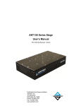
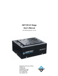
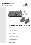
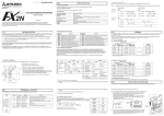
JY992D66101A DATE: JUNE 1997 PAGE: 1 OF 2 FX2N-422-BD COMMUNICATION BOARD USER’S GUIDE This manual contains text, diagrams and explanations which will guide the reader in the correct installation and operation of the FX2N-422-BD COMMUNICATION BOARD. It should be read and understood before attempting to install or use the unit. Further information can be found in the FX2N HARDWARE MANUAL and the appropriate manual for Programming or monitoring tools. 1. Introduction The FX2N-422-BD for RS422 communication board (422BD) can be connected to an FX2N Series programmable controller, and used as a port for programming and monitoring tools. When the 422BD is used, two DU Series units can be connected to the FX2N or a DU Series unit and a programming tool. However, only one programming tool can be connected at once. Only one 422BD can be connected to a base unit. Also, the 422BD cannot be used together with the FX2N-485-BD or the FX2N-232-BD. 2.External Dimensions Dimensions : mm (inches) Accessory : M3 self-tapping screws × 2 1 39(1.54") 46(1.81") 52(2.05") 2 35(1.38") Mounting holes (2-φ4.0(0.16")) Connector for programmable controller Connector (MINI DIN 8-pin) for peripheral unit The top face of this connector is higher than the top face of the panel cover of the programmable controller by approximately 3 mm (0.12") or by approximately 50 mm (1.97") when the cable is connected. 3 3. Suitable Products and Connecting Cables Product FX-20P-E Connecting cable FX-20P-CAB0 or FX-20P-CAB + FX-20P-CADP FX-10P-E Required 5V DC 180mA 120mA Personal computer F2-232CAB-1 + FX-232AW(C) + (FX-422ACB0 or FX-422CAB + FX-20P-CADP) *1 220mA FX-10DU-E FX-20P-CAB0 or FX-20P-CAB + FX-20P-CADP 220mA FX-20DU-E FX-20DU-CAB0 or FX-20DU-CAB + FX-20P-CADP 180mA FX-25DU-E,FX-30DU-E, FX-40DU-ES,FX-40DU-TK-ES, FX-50DU-CAB0 or FX-40DU-CAB + FX-20P-CADP FX-50DU-TK(S)-E *2 30mA *1: When using other products or cables please check the product manual for required 5V DC supply. *2: FX-2PIF can not be connected to the FX2N-422-BD. JY992D66101A DATE: JUNE 1997 PAGE: 2 OF 2 FX2N-422-BD COMMUNICATION BOARD USER’S GUIDE 4. Mounting procedure Turn off the power of the programmable controller, and mount the 422BD using the following procedure. 4 Remove the panel cover from the top face of the base unit. Connect the connector provided on the 422BD to the board mounting connector 1 3 provided on the base unit. Fix the 422BD to the base unit using the M3 self-tapping screws supplied. Tightening torque: 0.3 to 0.6 N•m (3 to 6 kgf•cm) Remove the cut out on the left of the panel cover using a tool such as nippers or 2 cutters so that the terminal block can pass through. 5.Specification 422BD 5.1 General specification General specifications are the same as those for the FX2N series programmable controller. 5.2 Power supply specification 5.3 Performance specification The 422BD requires 60mA 5V DC supplied from the programmable controller. The 5V DC power capacity of the programmable controller is 290 mA maximum. This is used by peripheral units and special function blocks as well as the 422BD. Make sure that the power capacity does not exceed this value. For the details, refer to the hardware manual. For additional current consumption increases, refer to section 3. Interface Conforming to RS422 Maximum transfer distance Total extension within 50m. Connector MINI DIN 8 pin Communication method Half-duplex communication system Protocol Programming protocol Isolation No isolation 6. Cautions for use 1) When using any 422BD, do not use any other communication format or parameters. If the communication format or parameters is set, programming is not possible. 2) Only one programming tool (such as FX-10P, FX-20P, etc.) should be connected to either the programming port or the port provided on the 422BD. If a programming tool is connected to both connectors, the following may occur. a) The program inside the programmable controller may not be consistent with the program inside the programming tool. If the program is modified or the set value for timers or counters is modified, a part of the program may be damaged and the programmable controller may malfunction. b) When the sampling trace function of the programmable controller is used from both ports, the correct sampling trace result cannot be obtained. 7. Diagnostics 1) Make sure that the cable connected is correct. 2) Make sure that the programmable controller is connected, and that the POWER LED is on. 3) Make sure that the communication format is in the initial state (D8120 = K0). Check using a peripheral unit how the communication parameters are set. If the no protocol (RS instruction) or the dedicated protocol is selected, set the parameters correctly using the peripheral unit. 4) Make sure that the RS, VRRD or VRSC instruction or N:N network setting program is not used in the program. If such an instruction is used in the program, delete it, turn off the power of the programmable controller, then turn it on again. 5) If the special auxiliary relay M8070 or M8071 is turned on, turn off the relay using the peripheral unit, turn off the power of the programmable controller, then turn on the power again.