1
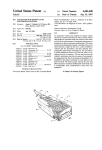
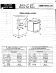
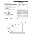
United States Patent [19]
Diiumer et al.
[54] CONTROL SYSTEM FOR AN OPERATING
EVENT IN A VEHICULAR POWER TRAIN
Nov. 15, 1983
FOREIGN PATENT DOCUMENTS
2900111
[75] Inventors: Rolf Diiumer, Weil der Stadt;
Winfried Kliitzner, Maulbronn;
Manfred Schenk, Fellbach, all of
Fed. Rep. of Germany
7/1980 Fed. Rep. of Germany .... .. 123/418
Primary Examiner—Raymond A. Nelli
Attorney, Agent, or Firm—Frishauf, Holtz, Goodman &
Woodward
[57]
[73] Assignee: Robert Bosch GmbH, Stuttgart, Fed.
ABSTRACT
To reduce the data processing requirements within
operating cycles of an automotive-type microprocessor
Rep. of Germany
or computer, the input/output unit has an angle incre
[21] Appl. No.: 326,507
[22] Filed:
4,414,946
[11]
[45]
ment counter receiving angle increment signals syn
chronized with rotation of the crankshaft of the engine,
Dec. 2, 1981
Fed. Rep. of Germany ..... .. 3100825
the counter providing output signals to comparators
which, when the count state reaches predetermined
values as applied from a data bus, derived from the
microprocessor, to the comparator, then provides out
[51]
Int. Cl.3 .................... .. G06F 15/20; G05B 15/02;
put signals to control the engine, for example by provid
ing ignition control output signals, fuel injection control
[52]
us. or. .................................. ..123/417;123/414;
[58]
Field of Search ............. .. 123/414, 417, 418, 480,
[30]
Foreign Application Priority Data
Jan. 14, 1981 [DE]
output signals, or the like. To further simplify computa
tional tasks of the microprocessor, the input/output unit
contains a timing element, for example a counter, which
can provide variable timing intervals, for example by
controlling the clock rate of the counter or a count
123/486; 123/416; 123/467
123/416, 424, 436, 437; 364/200, 424, 442, 900,
'
[56]
431
number, under control of the data bus, and a transfer
switch which selectively applies to a further counter
either the signals from the timing circuit or from the
crankshaft angle increment counter so that, as desired,
data then being processed in the microprocessor can be
References Cited
Us PATENT DOCUMENTS
_
4,178,893 12/1979 AOki .................................. .. 123/416
4’244'339 V1981 Gorilla """" "
123/416
4,250,858
2/1981 Jeemcke et a1. ..
Selectively based on or compared with engine Speed’ or
predetermined timing intervals, for consequential con
123/480
4,267,569 5/1981 Baumann etal..
t
123/417
4,304,256 5/1980 Klotzner ......... ..
123/480
4,373,l87 2/1983 Isbii et a]. ._.
123/480
4,603,539 l2/ 1977 Gorille et al. ..................... .. 123/418
u 516
l f th r
r tin
‘0.0 0 e °pe.a
et rs fth
gpmm 6. 0. .e eng
inc and the
enme POW“r "am System of Whlch 1‘ 1S 3 Pa“
10 Claims, 3 Drawing Figures
k, 27 VOLTAGE STABILIZATION CKT.
\
SPEED REFER INPUT Cm
m\ ‘I’ (m
I]
MARK ‘I
s‘>”—1
3“
9373
3
‘Du-1
‘"1
K 111
29
J
man 3714
T
_
2a~
h
a
-
‘
L——e“
.as;
2L
JUL
CLOCK FREQ. GEN.
INTERRUPT
NPUT-OUTPUT
UNIT
CLEAR
\231 22
\i“
2
11
Bx
21 m
AM
15~k
_
STARTER
THROTTLE
CLOCK \\
OTHER
AIR OUANTITYkINPUT
TEMPERATURE
1%
29a
ATA BUS
’’
N
“CONTROLS /
INJECTlON
‘:6
I
’
” "
‘L50 _ '5
55
5° elp big
52
\
'
\\\ ‘~41
'
\
Q18 A A
S2
63
i ‘A
”
~
'
READ
/\\ ‘COMMAND
u ’
\
\
WRITE COMMAND
‘ /SHIFT CONTROL
\
at‘
is
I
IGNI
all;
\
r11.
CONTROL
\
"“‘
,up
25
39 o i; \ “152b,,
312
\i
§~DATA BUS
\ '\
AD
"
DRESS BUS
US. Patent
Nov. 15, 1983
Sheet 1 of3
4,414,946
US. Patent
Nov. 15, 1983
Sheet 3 of3
4,414,946
UlJ
U L2
U78
LUZ-‘ll
1 I
FIG.3
4,414,946
1
2
CONTROL SYSTEM FOR AN OPERATING EVENT .
ing out extensive, and hence slow computational steps.
If the engine operates at 'high speed, the accuracy of
IN A VEI-IICULAR POWER TRAIN
signal processing by mathematical calculations suffers,
unless the number of bits is increased and the cycling or
Reference to related patents, application and litera
ture assigned to the assignee of this application:
U.S. Pat. No. 4,204,256, KLOTZNER.
U.S. Pat. No. 4,250,858, JEENICKE et al,
U.S. Pat. No.. 4,063,539, GORILLE et al.
5
for automotive use operate with eight-bit words.
The referenced U.S. Pat. Nos. 4,204,256 and
German'Patent Disclosure Document DE-OS No. 29
00 111,,JEEN1CKE et al.
clock time is made correspondingly high. To control,
for example, a fuel injection system, more than eight bits
are required for accurate computation although, usu
ally, the microprocessors which are readily adaptable
4,250,858, as well as the German Disclosure Document
>
Electronics,’ Jan. 20, 1977, page 102 et seq.
Electronic Design 1,1Jan. 4, 1977, page 34 et seq.
Elektronik, 1977, issue 4, page 48 et seq.
SAE-Paper No. 750 432, Application of Micro
processors to the Automobile,’ page 65 et seq.
'
DE-OS No. 2-9 00 111, describe microprocessor-input
/output combinations in which, to relieve the micro
processor of calculation tasks, the input/output units
are so arranged that they themselves can carry out
computational operations and counting. In such input
etz-b, vol. 28, 1976, issue 15, page 496 et seq.
Computer, August 1974, page 33 _et seq.
/output units, a problem similar to that of a wired pro
gram arises in that, for different types of IC engines,
RCA “User Manual for the CDP.,l8_O2 Cosmac Mi~>
different parameters must be sensed; the type and num
20 ber of parameters may depend on the engines and on the
croprocessor MPM-ZOlA“
,
RCA “Integrated Circuits, SSD-2l0, 4-76”,
the disclosure of the foregoing patents and literature
desires-or design requirements of the engine manufac
turer, and thus may require processing of different sig
being hereby incorporated by reference.
.
nals related to different engine parameters. Yet, to per
U.S. Ser. No. 326,509, ?led Dec. 2, 1981, by the in
mit mass production of input/output units suitable for a
ventors hereof, “SIGNAL STEERING AR‘ 25 number of different engines and, also, to permit inter
RANGEMENT IN AN AUTOMOTIVE-TYPE
changeability, it is desirable to provide input/output
MICROPROCESSOR SYSTEM."
units which are applicable for various types of appara
The present invention relates to controlling operating
tus and engines, or engine-vehicle combinations, which,
events in an automotive vehicularpower train system,
looked at from point of view of signal processing, means
for example controlling the ignition instant in an inter 30 various typesof power train systems.
nal combustion‘engine, that is, spark advance or retar
The Invention
dation, fuel injection quantity and/or timing, providing
signals when gear shifting to a higher or lower gear
should .be carried out, and/or control signals for an
It is an object to facilitate calculating operations for a
microcomputer or microprocessor, while permitting
automatic transmission'or the like, in which computer 35 rapid access by the microprocessor to parameters neces
equipment is utilized to determine the output as function
sary for its calculation, while providing 'for high vari
of operating conditions or the like of an automotive
abilityvin processing and handling of data representing
vehicle.
the parameters.
-
'
.
BACKGROUND
The referenced patents and literature describe vari
ous types of microprocessor controlled systems to mon
_
I
Brie?y, the microprocessor system includes a bus
system for connection to input/output units to sense,
respectively, operating parameters and provide respec
tive signals, and to supply control signals for switching
itor and furnish control signals for operating events in
stages. The input/output unit includes an angle incre
internal combustion engines, and particularly in internal
ment counter for periodic counting of numerical values combustion engines coupled to or forming part of a 45 supplied over a data bus, and to generate, upon estab
power train of a vehicle. Fixed wired computers to
lishing of a predetermined relationship with respect to
control operating events in an automotive vehicle, or in
input data—for example equivalence of counted num
bers—output signal for application to the microproces
the internal combustion (IC) engine therefor, is de
scribed in the reference U.S. Pat. No. 4,063,539; ?xed
sor. In accordance with the invention, a switch-over or
wired computers or signal processors have a disadvan 50 transfer switch system is provided which provides alter
tage with respect to microprocessor control signals in
native angle signals, and time interval signals derived
that the computer is poorly adaptable to universal use
from a timing unit, to the counter in the input/output
since the system is designed for a particular engine and
unit.
In accordance with a preferred feature of the inven
vehiclecombination, and thus cannot be individually
changed to ?t various types of engines or models of 55 tion, a plurality of comparators are used to control the
vehicles with which the engine is to be used, and which
output switching stages, for example an ignition output
all introduce different parameters which vary the re
stage. The comparators are associated with the angle
spective outputs from the computer, although the basic
increment counters deriving signals representative of
computational methods may all be the same. Micro
rotation of the crankshaft of the IC engine——directly or
processor systems have the advantage of being readily
adaptable to different types of engines and power train
systems. They are subject to improvement, however,
indirectly. Counting sequences being carried out by- the
angle increment counters thus can be utilized for con
trol of various parameters, that is, for example to con
since they are coupled to a multiplicity of input units
trol any respective desired number of output stages.
This system, then, can be used in lieu of a high-tension
and also output units,-and thus must retain a substantial
data base ‘and hence memory locations, which are re 65 ignition distributor with only minor additional appara
tus requirement, thus avoiding the necessity of a me
tained in fixed memories, for example read-only memo
chanical distributor unit, and consequent difficulties
ries (ROMS). Comparatively complex programs are
associated therewith.
necessary to process externally applied signals by carry
4,414,946
3
Synchronization, in accordance with a feature of the
invention, of the periodic counting systems in the angle
increment counter, can be obtained "by associating a
certain angle marker transducer, coupled to the crank
shaft or the camshaft of the ICengine. The ignition
cycle in" a four-stroke IC engine requires 720° of crank'i
shaft'rotation. Thus, the crankshaft markers which can
be‘accurately placed on the crankshaft can'be utilized
4
stage in the microprocessor 10 which is provided to set
predetermined, initial conditions within the micro
processor "10; v'for'example completely clear conditions,
or the entry of information thereinto upon starting of a
new program from either ROM 12 or RAM 11, and
transfer of such conditions-if commanded—to_ the I/O
unit 13. The condition, in the I/O unit 13 for example,
may be a complete clearance of any data therein.
A frequency generator 24 is provided, furnishing
for synchronization; camshaft markers thenare used to
determine the initiation 'or beginning of a 720° cycle. A O clock signals for the microprocessor 10. The frequency
derived therefrom is then, preferably, divided in suit
simple AND-function logic gate is then all that is
able frequency dividing networks in the‘microproces's‘or
needed to control the further signal processing.
10 and connected to a terminal 25 :forming the clock
The system has the advantage that the calculating
terminal of the I/O 'unit 13. Power supply is obtained
operations which are concerned, essentially, with deter
mining relationships between counting states, for exam 5 from an external source providing a voltage U at termi
ple equality, and counting, sensing of measured values,
and outputs of control signals are removed from the
microprocessor and transferred to the input/output
(I/O) unit. This substantially reduces the loading on'the
microprocessor and permits rapid access to parameters.
The control of the particular relationship to be obtain
can remain within the microprocessor. The system has
a high degree of ?exibility in regard to sensing and
nal 26, which is connected to a voltage control or stabi
lization circuit 27 to provide stabilized output voltages
at a terminal 28 which is connected to all elements
containing electronic components. Only two such con
nections areshown for simplicity of the drawing.
The input/output unit is connected to an input circuit
29 which has seven inputs 30-36, each of which is con
nected to an external signal or data source. The external
data sources provide signals to’ the input circuit 29, for
processing of parameter data. The changes can be con
trolled from the microprocessor. Thus, the system can 25 ‘processing by the I/O unit 13, which are representative
be used with various types of engines, having different
numbers and types of input/output signal requirements,
and can be readily adapted to various types of engines
and power train systems.
DRAWINGS
FIG. 1 is a block diagram of a microprocessor system
for an internal combustion engine, in accordance with
the‘prior art;
_
Inputs 30, 31 are connected to a transducer system 37
which has a star or gear disk 370 coupled to the crank
shaft of the IC engine, and formed with a plurality of
teeth 371 at its circumference. Rotation of these teeth is
sensed by a first transducer 372. The teeth areferromag
netic, the transducer is inductive, and change of flux
within the transducer 372 causes a voltage signal to
v
FIGL'Zis a‘ block diagram of an input/output unit in
accordance with ‘the/present invention; and
of operating parameters or conditions of ‘the power
train system.
p ‘
_ "
FIG. 3 is a‘ sequence of timing graphs used to explain
the operation of the system and the method in accor
dance with the invention.
arise at the output terminal thereof‘. The signal seé
'quence, which‘will bei'speedédep'eiident, is applied to
the input of the inpufcircuit 29. Rather than using ferro
magnetic teeth, other systems may be used which can be
scanned by a transducer, for example a disk may be
’ FIG. 1 illustrates a microprocessor system in which a 40 made which is premagnetized in strips adjacent its cir
cumference; or a disk with openings can be used which
microprocessor 10 is connected to a random access‘ or
working memory (RAM) 11. Data which are ?xed are
stored in a ROM 12; for some uses, the ROM 12 may be
an erasable programmable ROM, or merely a program
' mable ROM (EPROM; PROM). The system further 45
includes an input/output unit 13. A data bus 14 connects
can be scanned optically. The disk 370 additionally
carries a reference marker 373, which is scanned by a
second transducer 374 to apply a referenced marker
signal to the input 31.
v
A further transducer system 310 is provided, coupled
to input 32. The transducer 310 has a disk 311 coupled
to the camshaft of the IC engine, on which a reference
marker 312 is applied. The reference marker 312 is
50 scanned by a third transducer 313. Of course, the teeth
ROM 12.
i
371 could also be applied to the disk 311, and scanned
The data bus 14, for example, may be a bus having
the microprocessor 10, RAM 11, ROM 12, and the
input/output (I/O) control unit 13. An address bus 15
connects the microprocessor 10, the RAM 11 and the
eight individual lines, in dependence on the number of
by the transducer 372. The frequency of the pulse se
bits to be transferred. An additional chip selection line
quence then, of course, would be half.
may be necessary in order to select one or more elemen
tal units within the I/O unit, or stage 13. The micro
processor 10, RAM 11 and ROM 12 are connected by a
read-command line 16 in order to control information
' flow which is applied or stored. A write-command line
18 is provided in order to read in or record information
Further information regarding the operating condi
tions and ambient conditions of the 1C engine or the
vehicle, respectively, are: temperature T; quantity ‘of air
being admitted to the induction pipe of the engine L;
position of the throttle switch" 38; position of start
switch 39. The temperature-air-throttle switch position
in the RAM 11. A program interrupt line 20 is provided, 60 and starter switch position‘ are connected'in the form of
input signals applied to terminals 33-36 of the input
interconnecting the I/O unit 13 over terminal 21 with
the microprocessor 10. This interrupt line is used in
circuit.
order to‘ interrupt a program which is being run in the
microprocessor if predetermined'information is placed
’
i
i
’
Other and additional information can be applied to
the input circuit, and the type of information parameters
in the I/O unit 13. The microprocessor 10 has a “clear” 65 described herein is not limited to those listed; for exam
ple, additional inputs can be applied in ‘the form of:
command terminal 22, which is connected to the
level of unstabilized supply voltage U;
"
‘
“clear” terminal 23 of the I/O unit 13. The 'clear com
output signals from an engine knock sensor;
mand terminal 22 is connected to a suitable clearing
5
4,414,946
6
output signals representative of engaged gearing;
ent case signals to control ignition, fuel injection, and
gear shifting, is then transmitted to the output stages 49,
50, 54, 61 to carry out the desired switching commands,
and effect the respective output actions. Final results
and such other further information signals as may be
and intermediate results can be stored in the RAM 11
output signals from an exhaust gas composition sensor;
pressure within the induction manifold;
output torque delivered by the engine;
required.
Collectively, all these further signals are indicated by;- a
for possible recall by the microprocessor 10.
The number of microprocessors used, of ROMs and
single input, schematically shown byarrow 29a, con
RAMs, is not limited to that shown in the ?gure and
nected to input circuit 29.
specifically described; it may be expanded in depen
All the input signals, that is, the seven input signalswhich, preferably, form the minimum number-as well
dence on information which is to be processed, the
scope of the program, and the scope of the data which
are to be stored, and/or to be processed. The number of
microprocessors, and storage locations in the RAM 11
as well as in the ROM 12, will depend on the construc
as additional input signals at terminal 29a are processed
in the input circuit 29 to remove noise and spurious
signals therefrom, for example by ?ltering and, if pro
vided in analog form, to convert the signals into digital
form by suitable analog/digital converters. A suitable
tional type of the system, and the possibility of long
analog/digital converter uses a voltage controlled oscil
storage, and the availability of respective storage loca
lator (VCO) for transforming analog information into
digital or frequency-type information. Signal process
ing, noise suppression and the like, may utilize, for ex
tions.
FIG. 2 illustrates a portion of the input/output unit
time memory as well as short-time memory and buffer
13, arranged in accordance with the present invention.
Terminal 40—see also FIG. 1—has a pulse-type speed
signal applied thereto. Terminal 40 is connected to a
bounce suppression circuits, circuits to prevent over
frequency multiplying stage 70 which, in turn, is con
voltages, protective circuits with respect to over-volt
nected to the clock input C of a crankshaft angle incre
ages, short circuits and the like, may also be used, as
25 ment counter 71. Terminals 41, 42—see also FIG. 1—
well known.
'
carrying reference marker signals are connected over a
The input/output unit 13 is connected to switching
selection input circuit 72, the output of which is con
output stages 49, 50 over output terminals 47, 48. The
nected to an OR-gate 73 which is connected to the
output stages 49, 50 are ignition stages which, as is
loading pulse input PE of the counter 71. The two ter
customary, include a semiconductor switch, such as a
transistor, in the primary circuit of an ignition coil. The 30 minals 41, 42 in the selection circuit 72 are selectively
connectable by transfer switches 74, 75 either directly
secondary circuit includes at least one spark plug or
20
ample, Schmitt trigger circuits. Additionally, contact
spark gap 51, 52, respectively. A further output circuit
54 is provided to control fuel injection to inject fuel, for
example, gasoline, by four injection nozzles 55-58. The
fuel injection output terminal 53, connected to I/O unit
13, provides the control pulses to the fuel injection unit
or over an inverter 76, 77, respectively, to an AND-gate
78. The output from the AND-gate 78 is selectively
connectable over a further switch 79 directly or over an
35 inverter 80 to the OR-gate 73. The transfer switches 74,
75, 79 may be formed, for example, by transmission
54. An additional output control unit 61 is illustrated
which is connected to terminals 59, 60 of the I/O unit
gates and are controlled from the data bus 14 through a
13, and is utilized to control transmission shifting by
81 has a control input 82.
The overflow output C0 of the counter 71 is con~
nected to the other input of the OR-gate 73. A buffer
memory 83 is connected to the data bus 14. The buffer
transfer switch decoding stage 81. The decoding stage
selectively energizing or de~energizing hydraulic valves
62, 63. Various other output elements may be used.
The system is described with respect to a four-cylin
der engine; two ignition control systems 49, 50 are
shown, and each one of the spark gaps 51, 52 represents
two spark plugs, in different cylinders. The spark plugs
can spark or ?ash over in unison; one of the spark plugs
sparks at the required ignition instant, which will be
before the respective piston has reached top-dead-cen
ter (TDC) position, compressing the fuel-air mixture in
the respective cylinder. The other spark plug, which
also flashes over, will not cause any ignition event,
since, at that time, the exhaust valve from the respective
other cylinder will be open and the spark will, ineffec
tively, occur while burned combustion gases are being
exhausted.
Basic Operation: The above referenced literature has
described the general operation of the system; the hand
books issued by manufacturers of microprocessors and
associated apparatus are also referred to, in which the
memory 83 has an entry or transfer control terminal 84.
The count inputs of the counter 71 are connected to >
45
count comparison inputs of three comparators 85, 86,
87. Comparison count inputs of the comparators 85, 86,
87 are connected through buffer storage or memories
88, 89, 90 which, respectively, are controlled by signals
at terminals 91, 92, 93, the buffer memories being con
nected to the data bus 14. The count outputs of the
counter 71 are connected through a gate 68, which has
a control terminal 69, to the data bus 14.
The outputs of the comparators 85, 86 control, re
spectively, each a JK ?ip-?ip (FF) 94, 95 which form
55 the output stage control elements for the ignition con
trol unit 49, 50. The J inputs and the K inputs of the FFs
94, 95 are connected to control terminals 97, 98 and 66,
67, respectively.
In accordance with a feature of the invention, a trans
construction and circuit connection of the components 60 fer switch 99 is provided, having one terminal con
nected to the output of the comparator 87, and the other
are described in detail; operation and programming,
to a timing element 108 formed by a counter. The trans
likewise, is described therein, as well as variations in
fer switch 99 has its switching element connected to the
constructions and various connection possibilities. The
reset input R of a counter 100 as well as to the SET
referenced RCA manuals are particularly instructive.
input of a buffer store 101. Transfer switching of the
The program stored in the ROM 12 is processed in
switch 99 is controlled from the data bus‘ 14 over a
the microprocessor 10 with respect to the information
transfer switch decoding stage 102. The decoding stage
derived from the input circuit 29 and applied by the
102 is controlled from a control terminal 103. The count
input/output unit 13. The computed result, in the pres
7
4,414,946
8
inputs of the buffer store 101. The count outputs of the
the camshaft is utilized in order to determine the 720°
range of crankshaft rotation. Markers 373 and 312 are so
buffer store 101 are connected over a gate 104, which
arranged that generation of a signal U42, from marker
has a control terminal 105, to the data bus 14. The clock
input C of the counter 100 can be selectively connected,
under control of the data bus, with terminals 40, 43 or
44 .(FIG. 1) or other parameter-dependent counting
312, also causes generation of a signal U41 from marker
373. The signal U42 is longer. Upon simultaneous oc
currence of signals U41 and U42, the output of the
AND-gate .78 provides a synchronizing signal U78,
frequencies. The data bus 14 is additionally connected
which characterizes the beginning of a new crankshaft
over a buffer memory 106, which has a control terminal
revolution cycle of 720°—two revolutions.
The inversion possibilities in the selection circuit 72
outputs of the counter 100 are connected to the count
107, with the count inputs of the timing counter 108.
The clock input C of the counter 108 is connected over
are utilized to match the system to various types of
terminal 109 with a counting clock frequency. Various
clock frequencies could be connected to the terminal
109, under control of data derived from the data bus 14,
for example under control of a further decoding circuit.
Reference is made to the US Pat. Nos. 4,250,858 and
transducers 37, 310. If, for example, the signal U41
4,204,256, as well as to the DE-OS No. 29 00 111, for
further details of control of the timing counter 108. The
counter over?ow terminal C0 of the counter 108 is
connected with the SET input PE thereof and, addi
tionally, or alternatively, can be connected to the out
put of the comparator 87 by the transfer switch 99 with
the RESET input of the counter 100 in dependence on
the position of the switch 99.
The control terminals 66, 67, 82, 84, 91, 92, 93, 97, 98,
103, 105, 107 receive control signals through a decoding
would be generated as a negative signal, then the trans
fer switch 74-under program control—is changed
over, sothat the signal can be inverted by inverter 76.
Similar considerations apply to the signal U42. Inverter
79 is used to determine that flank of the signal U41 at
which the counter 71 should be set. In the present exam
ple, counter 71 is set with a positive ?ank, and this
setting should occur at the second ?ank of the signal
U41. Thus, inverter 80 must be used in order to invert
the signal U78. If the counter 71 is to be set by the ?rst
?ank of the signal U41, transfer switch 79 must be
changed over. The selection circuit 72, thus, through
the program of the microprocessor, can be utilized to
match the system to any type of transducer system, by
entering respectively appropriate code words into the
device—not shown-—as described in the aforemen
decoding stage 81. Circuit 72, thus, functions as a signal
tioned referenced patents and German Disclosure Doc
polarity selection circuit under control of decoder 81.
ument to determine the sequencing of the control sig
The ignition output control stages 49, 50, connected
nals in dependence on the program which is run in the 30
to terminals 47, 48, are controlled by the comparators
microprocessor. Reference is also made to the litera
ture, and particularly the manufacturer’s literature how
v85, 86. Similarly, the output stages 54 for fuel injection,
and 61 for gear shifting or transmission changes can be
sequencing control signals can be derived from a micro
controlled by similar comparators. Numerical values
processor in which a program is being run, and in which
the control signals depend on the state of respective 35 Z88, Z89-FIG. 3—are determined in the microproces
sor, in dependence on the parameters to be sensed, and
program conditions.
applied over the data bus 14 to the buffer memories 88,
Operation, with reference to FIG. 3: The crankshaft
89. Storage is controlled by control signals applied to
angle increment counter 71 is set to the numerical value
the respective terminals 91, 92. The value of the number
V83 stored in the buffer memory 83 when a signal is
derived from the selection circuit 72 each time after two 40 Z88, Z89 is changed at the time instants T1 to T5 in
order to provide data characterizing the beginning and
full rotations of the crankshaft, that is, after 720° rota
the end of the closing time of the ignition switch con
tion thereof. Upon being set to the value Z83, the
trolling current ?ow through an ignition coil, and con
counter counts down in the rhythm of the angle incre
tained within the stages 49, 50. FIG. 3 illustrates the
ments as determined by the teeth 371, transduced by
transducer 372, and available at the terminal 40 (FIG. 45 value Z88 as a chain-dotted line, and the numerical
value Z89 as a dotted line.
2). When the counter has reached the value null or zero,
Upon equality of the applied numerical values, com
an over?ow signal at the counter over?ow terminal CO
parators 85, 86 provide output pulses U85, U86 which
thereof or a signal from the OR-gate 73 resets the
cause the state of the J K-FFs 94, 95 to change in depen
counter back to the count number Z83, and starts anew
to count down. The count number Z83 is so set that the 50 dence on the control signals applied to the respective
terminals 66, 67, 97, 98. The output signals U47, U48
angle increment counter 71 will have that number of
determine the closing time or dwell time of the ignition
count cycles occur therein which corresponds to the
output stages 49, 50. Signal U47 is applied to the igni
numbers of cylinders of the IC engine within a range of
tion system associated with cylinders two and four of
720° of rotation of the crankshaft. This is effective for
all four-stroke IC engines. The illustrated example re 55 the four-cylinder engine, and signal U48 controls the
ignition system associated with cylinders one and three.
fers to a four-cylinder IC engine. Synchronization is
effected after each 720° of crankshaft rotation by the
selection circuit 72, that is, if for example due to mal
function, interference, noise or disturbance pulses, an
The ignition instants, controlling generation of the
spark at the respective spark plug, are indicated by the
designation Z1, Z2, Z3, Z4. In known manner, the spark
after each 720° rotation of the crankshaft. This is illus
trated in the ?rst cycle of FIG. 3. The arrangement is
plugs of cylinders one and three on the one hand, and of
cylinders two and four on the other, are simultaneously
energized to have an ignition spark ?ash over. This
used to generate an internal or electronic reference
ignition spark will ignite the air-fuel mixture in the
error should have occurred, the error will be eliminated
closed cylinder, which is just about to change from the
marker or reference marker signal. Since the marker
.373 coupled to the disk 370 (FIG. 1) connected to the 65 compression stroke to the power stroke, and will be
‘ineffective with respect to the burned combustion ex
crankshaft of the engine due to the higher speed pro
haust gases of the other cylinder; in other words, the
vides more precise signals U41, and this marker occurs
ignition spark will occur in an ambient surrounding
at each 360“ of crankshaft rotation, the’ marker 312 on
4,414,946
which, in one cylinder, contains an ignitable ‘mixture,
and in the other cylinder contains exhaust gases. vThe
10
The system is highly flexible, since different parame
ters derived, for example, from the terminals 40, 43, 44,
control signals on the terminals 66, 67, 97, 98 are applied
at uniform intervals between two closing time periods,
that is, in the FF 94 for example at the time instants t1,
t3, t5, etc. This permits setting an extinction determined
by the program, in which the time instants are deter
can be counted in a single counter 100 either to
mined by the output signals from comparators 85, 86.
Further possibilities of invasion of the system, resulting
The count result derived from counter 100 is then
stored in the buffer store 101, for interrogation when
required..The I/O unit 13 thus is rendered much more
versatile and variable with respect to sensing of parame
ters, and can readily be adapted to different types of IC
engines, in different types of power train systems for
various types of vehicles, as required, for example, by
variable demands of different automotive manufactur
in instantaneous setting and extinction, can be obtained
by the program, for example by direct setting and reset
ting inputs having higher priority. The system de
scribed permits use of a single counter 71 which is com
puter'controlled to then in turn control a plurality of
output stages while avoiding the necessity of a mechani
cal high-voltage distributor, permitting, further, over
lap of closing times. A speci?c association of cylinders
(a) during a variable crankshaft angle interval-as
determined by comparator 87, or
(b) during a variable time interval, as determined by a
timing element, formed by timing counter 108.
ers.
»
to the computer is not needed since this is obtained
The respective count states of the counters, as well as
the operating states of the output stages, can of course
within the I/O circuit 13.
be interrogated by suitable control signals applied for
~
.
Y
'
example over the data bus 14—-see, for example, the
referenced US. Pat. Nos. 4,204,256, 4,250,858 and the
manner by a suitable number of comparators, of course,
German Disclosure Document DE-OS No. 29 00 111.
is not limited to two output stages, but can be expanded
Such interrogation is shown in the present application
as desired; even a larger number of comparators can
readily be controlled by the counter 71 which is the 25 only for the counter 100 and for the counter 71, by gates
104 for counter 100, and 68 for counter 71, respectively.
only counter needed to generate the respective trigger
Various changes and modi?cations may be made
signals.
within the scope of the inventive concept.
The comparator 78 is used to generate rotary angle
We claim:
intervals during which sequences of signals which de
1. For combination with a vehicular power train,
pend on operating parameters are to be processed. In 30
a control system to control an operating event within
the presentexample, that is, of a four-cylinder IC en
said power train and having a rotating shaft, said
gine, the intervals are 180° intervals. These intervals can
control system having
be changed, as desired, under computer control, if dif
a microprocessor unit (10);
ferent numerical values Z90 are applied through the
' an input/output (I/O) unit (13);
buffer memory 90 from the data bus 14. The angle sig
a data bus system (10) interconnecting the micro
nals U87--FIG. 3—generated in the comparator 87 are
processor unit and the input/output unit;
used in the counter 100 as reset signals which, each
a plurality of input sensor elements (37, 310, 372, 374,
time, start a new count cycle in the counter 100. During
The number of the output stages controlled in this
any such count cycle, a parameter-dependent frequency
is counted, for example the quantity of air induced
through the induction pipe of the engine, as represented
by a pulse signal of frequency dependent on the air
quantity. The count state Z101 is transferred, shortly
before reset, into the buffer store 101 and, as needed,
can be interrogated by the microprocessor 10 by apply
ing an interrogation control signal to the gate control
313, T, L, 38, 39, 29a) providing sensing signals
representative of operating parameters of the
power train, connected to and providing said sens
ing signals to the input/output unit,
one of said input sensor elements (370, 372) forming a
crankshaft angle increment transducer (37) provid- .
ing a train of crankshaft increment signals;
a plurality of output stages (49, 50, 54, 61) ,for carry
ing out operating commands connected to and
terminal 105, and then interrogating the buffer store 101
through gate 104. Thus, a signal which has been derived
from the counted frequency corresponding to air quan
tity, counted during an angular interval, can be obtained
a crankshaft angle increment counter (71) connected
which is directly representative of fuel injection time.
Other frequencies depending on operating or ambient
rate determined by the frequency of said pulse
parameters, for example speed-dependent frequencies
a ?rst comparator (83) connected to the angle incre
or temperature-dependent frequencies have to be 55
counted during an angular interval corresponding to a
?xed time interval. In this case, the decoding stage 102
causes change-over of the transfer switch 99 so that the
time interval to limit the counting cycle of the counter
100 is determined by the timing counter 108. This time
interval can be varied by applying either different
counting values to the timing counter 108 over buffer
memory 106 as controlled by control terminal 107 or by
changing the counting frequency at the terminal 109. In
dependence on the count number provided by the
buffer memory 106, or the count rate as determined by
input 109, a reset signal for the counter 100 is generated
by the timing element formed by counter 108.
controlled by the input/output unit;
to receive said crankshaft angle increment signal
train and counting the pulses of said pulse train at a
train;
ment counter and to the data bus to receive a com
parison signal from the data bus (14) and providing
a ?rst output signal when the count output from
said angle increment counter (71) and from the data
bus have a predetermined relationship,
said output signal being connected to at least one of
the output stages to control operation thereof;
a second comparator (87) connected to the angle
increment counter (71) and to the data bus (14) to
receive a comparison signal from the data bus and
providing a second output signal when the count
output from the angle increment counter and from
the data bus have a second predetermined relation
ship;
‘1,414,946
11
‘12
,
chronization signal when there is overlap between the
respectively applied signals.
,
6.'Syster'n‘ according to claim 4, wherein the selection
circuit‘ (72) further includes selectively connectable
direct and inverting inputs, and ‘controlled transfer
switch means (74, 75, 79) controlled by data from said
a second counter (100) having its" output connected to
‘the ‘data bus (14) to provide output signals thereto
for processing in the microprocessor unit (10) in
accordance with a selected parameter or value, as
determined by the signal applied to the second
comparator (87) from the data bus,
and comprising, in accordance with the invention,
data bus (14) to, selectively, connect direct or inverting
inputs to the respective transducers and, selectively, to
the crankshaft angle increment counter for matching of
a timing circuit (108) providing timing signals;
and transfer switch means (99) having its switching
state controlled by data from the data bus (14) and
transferring to the second counter (100), selec
tively, and in accordance with the switching state
polarity of signals supplied by respectively different
types of transducers connectable in said system.
7. For combination with a vehicular" power train, a
control system to control an operating event'within said
power train, said power train having an engine includ
(a) the output signals from said second comparator
15 ing a crankshaft and a camshaft;
(87), or
t
said control system having an input sensor element
(b) the timing signals from the timing circuit (108),
(370, 372) coupled to the crankshaft of the engine
to control the counting cycle of the second counter
and forming a crankshaft angle increment trans
(100) selectively by
ducer (37) providing a train of crankshaft incre
(a) the parameter-dependent pulse train derived from
thereof,
ment .signals;
the second comparator (87), as counted by said
angle increment counter (71), or
a crankshaft angle increment counter (71) connected
to receive said crankshaft angle increment signal
train and counting the pulses of ‘said pulse train at a
(b) the timing interval of the timing circuit (108),
and wherein the angle increment counter (71), the
second counter (100), said ?rst and second compar
ators (85, 87) and the timing circuit (108) form part 25
rate determined by the frequency of said pulse
train;
,
of the input/output unit, to permit the input/output
a reference marker (373) and reference marker trans
unit to provide data to the data bus, and hence to
ducing means (374) coupled to said crankshaft and
providing ‘a marker signal representative of a pre
the microprocessor, selectively, based on signals
determined angular position of said crankshaft;
‘ processed by a single shaft angle increment counter
(71) or, selectively, based on time intervals deter
mined by said timing circuit (108).
2. System according to claim 1, wherein the timing
circuit (108) is a counter connected to and controlled by
the data bus (14), saiddata bus providing data to said
counter controlling at least one of: counting rate; count 35
)
different from said crankshaft;
.
and a selection circuit (72) receiving at least one of
said crankshaft signals ,and said ,camshaft angle
‘signals,
'
V
‘
'
.
said selection circuit including an AND-function
circuit (78) providing a synchronization signal, said
synchronization signal being connected to and
synchronizing the angle increment counter (71).
number.
7 -3. System according to claim 1, further comprising at
least one additional comparator (86) connectedto the
angle increment counter and to the data bus to receive
a comparison signal from the data bus (14), and provid
a camshaft angle transducer (310) coupled to the
camshaft of the engine and operating at a speed
40
8. System according to claim 7, wherein the camshaft
ing an additional output signal when the count output
from the angle increment counter (71) and from the data
bus have an additional predetermined relationship, the
angle transducer provides output signals in pulse form
output signal from the additional comparator being
ducer, the AND-function circuit'providing said syn
having a greater pulse width than the output signals
derived from the crankshaft angle increment trans
connected to at least a further one of the output stages 45 chronization signal when there is overlap between the
respectively applied signals.
(50, 54, 61) to control the operation thereof.
4. System according to claim 1, wherein the power
9. System according to claim 7, wherein the selection
circuit (72) further includes selectively connectable
direct and inverting inputs, and controlled transfer
switch means (74, 75, 79) controlled by data from said
train includes a camshaft;
said input sensor elements include a camshaft angle
transducer (310);
data bus (14) to, selectively, connect direct or inverting
inputs to the respective transducers and, selectively, to
the crankshaft angle increment counter for matching of
and a selection circuit (72) is provided, receiving both
said crankshaft angle signal pulse train and said
camshaft angle signal pulse train, said selection
polarity of signals supplied by respectively different
circuit includes an AND-function circuit (78) pro
viding a synchronization signal, said synchroniza
tion signal being connected to and synchronizing
the angle increment counter (71).
55 types of transducers connectable in said system.
' 10. System according to claim 7, wherein the marker
on the camshaft rotates through 720° of crankshaft
having a greater pulse width than the output signals
angle rotation to provide positive association of count
ing events with respect to the strokes of a four-stroke
engine regardless of spurious or interference or noise
derived from the crankshaft angle increment trans
pulses.
' 5. System according to claim 4, wherein the camshaft
angletransducer provides output signals in pulse form
,
i
ducer, the AND-function circuit providing said syn
65
t
1
i
i