1
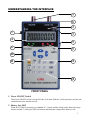
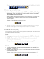
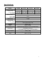
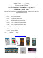
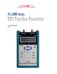
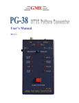
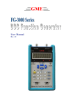
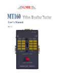
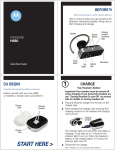
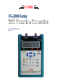
GME User Manual Rev. 1.1 TEST INSTRUMENT SAFETY GUIDELINES WARNING An electrical shock of over 10 milliamps of current to pass through the heart will stop most human heartbeats. Voltage as low as 35 volts dc or ac rms should be considered dangerous and hazardous since it can produce a lethal current under certain conditions. Be sure to observe following safety precautions: 1. Do not expose high voltage n eedlessly in the equipm ent unde r test. Re move housings and covers only when necessary. Turn off equipment while making test connections in high-voltage circuits. Discharge high-voltage capacitors after removing power. 2. If possible, fa miliarize yourself with the equ ipment being tested and the location of its high voltage points. However, rem ember that high voltage m ay appear at unexpected points in defective equipment. 3. Use an insulated floor material or a large, insulated floor mat to stand on, and an insulated work surface on which to place equipment; make certain such surfaces are not damp or wet. 4. When using a probe, touch only the insulated portion. Never touch the exposed tip portion. 5. When testing ac powered equipm ent, remember that ac line voltage is usually present on some power input circuits such as the on-off switch, fuses, power transform er, etc. any tim e the equipment is connected to an ac outlet, even if the equipment is turned off. Limited One-Year Warranty GME Technology warrants to the original purchaser that this product and the component parts thereof, will be free from defects in workmanship and materials for a period of one years from the data of purchase. GME Technology will, without charge, repair or replace, at its’ option, defective product or component parts. Returned product must be accompanied by proof of the purchase date in the form a sales invoice or receipt. Term and Conditions The warranty period is based upon the invoice date of the original purchase by the end-user. Warranty only applies to defects in materials and/or workmanship, which occur during normal use. Warranty does not apply to those products that are damaged due to misuse, abuse, negligence or modification. Warranty does not extend to any damage that occurs in shipment or due to natural phenomenon (i.e. lightning or line surges). Warranty will be voided if the original serial number on the product is removed by accident or intentionally This warranty gives you specific rights and you may have other rights, which vary from state-to-state. Service & Repair The following are procedure for returning a GME product for servicing and repair. Turn around time for repair is normally within five (5) working days excluding shipping time. RMA Procedure Before sending your GME product in for service, be sure to contact GME Technology first to obtain a RMA number. If your product is still under warranty, please send in the product along with a copy of the invoice or receip t showing the date wh en the product was purchased. If the warranty has already expired, please ask for the repair cost when you contact GME Technology for the RMA number and include a check or m oney order for the repa ir cost when you send in the product. Please make check payable to: GME Technology You may send your GME product to our service & repair department at: GME Technology ATTN: Service & Repair Department 380 S. East End Ave., #H Pomona, CA 91766 Be sure to include a note showing your RMA number, your name, telephone number, return address, and a description of the problem with the product. For the most recent support information, please visit GME Technology website at www.gmetechnology.com/support Table of Contents Page INTRODUCTION …………………………………………………………………. 1 ITEM CHECKLIST …..…….…………………………………………………….... 1 FEATURES ….……………………………………………………………………... 1 UNDERSTANDING THE FRONT PANEL …….……………………………….... 2-3 OPERATION ….……………………..…………………………………………….. 4-5 SPECIFICATIONS …………………………………………………………………... 6 GME PRODUCTION INFORMATION ……………………………………………… 7 NOTES ……………………….…………………………………………………….. 8-9 INTRODUCTION Thank you for purchasing the FG-2000 series DDS function generator. The FG2000 series function generato r utilize advance Direct Dig ital Synthesis ( DDS) technology to create highly accurate and stab le output signals including sine, square, and triang le waveforms up to 20MHz with 5V peak-to-peak amplitude in a portable hand-held unit. There are four m odels in the FG2000 series , FG2005, FG2010, FG2015, and FG2020, featuring up to 5MHz, 10MHz, 15MHz, and 20MHz maximum output waveform frequency respectively. The FG2000 series also feature a num erical keypad for simple frequency setting, an 8-digit LCD frequency display, and built-in non-volatile m emory for store/recall up to 50 setup param eters. The FG2000 series function generator comes in a rugged, highly portable package that is ideal for on-the-bench and inthe-field testing. There are two BNC connectors for sim ultaneous sine/triangle and square wave output. The FG-2000 series al so feat ure vari able sine and triangle wave am plitude contro l. T he ins truments can be p ower from the included 7.5V AC adapter or a standard 9V battery. ITEM CHECKLIST FG-2000 series DDS function generator One 7.5V AC power adapter One protective rubber boot One User’s Manual FEATURES Up to 20MHz output frequency and 5V peak-to-peak amplitude DDS technology with microprocessor control for clean and accurate waveform Multiple output waveforms include sine, triangle, and square wave Numerical keypad for simple and accurate frequency setting up to 0.2Hz step 8-digit LCD frequency display Two BNC outputs for simultaneous square waveform and sine/triangle waveform output Sine/triangle waveform amplitude adjustable up to 5V peak-to-peak Built-in flash memory for store/recall of up to 50 setup parameters (both frequency value and waveform type) Low battery indicator AC adaptor power source or standard 9V battery operation Ideal for on-the-bench and in-the-field testing Easy to use, lightweight, and portable UNDERSTANDING THE INTERFACE 7 8 2 1 3 4 9 6 5 10 11 13 12 FRONT PANEL 1. Power ON/OFF Switch This Power ON/OFF switch is on the left side of the unit. Slide the switch upward to turn the unit on and downward to turn the unit off. 2. Battery Low LED When the FG-2000 is operating on a standard 9V battery and the voltage on the battery has drop down to around 7V, this green LED will turn on indicating the voltage on the battery is low. 1 3. 7.5V DC Adaptor Input Plug in a 7.5V 200mA 5.5mm x 2.1mm center positive AC adaptor to power the FG-2000 series function generator. 4. Frequency LCD Display This 8-Digit LCD display shows input/output frequency value information. 5. Frequency Unit Display These indicators will light to show the unit f or the frequency value currently displayed on the 8Digit LCD screen (i.e. MHz, KHz, Hz). 6. Output Waveform Type Display These indicators will light to shows the type of wa veform being output (i.e. sine wave or triangle wave). NOTE: square wave is always being output on the square wave BNC output connector so no indicator will be shown for the square wave. 7. SQUARE Wave Output (BNC) Outputs the square waveform of selected frequency. 8. SINE/TRI Output (BNC) Outputs either sine or triangle waveform of selected frequency depending on the output waveform type selected. 9. Amplitude Control Knob for Sine/Triangle Waveform The am plitude control knob is on the right side of the unit and is used to adjust the level of the sine/triangle waveform output. NOTE: Square waveform output is fixed at 5V peak-to-peak and can not be adjusted. 10. Modify Keys Use the lef t/right m odify keys to s elect the d esire digit on the LCD display to modify; use the up/down modify keys to increment/decrement the value of the selected digit. 11. SHIFT Key Status LED Press the S HIFT key to turn this LED ON/OFF. W hen this LED is on, the secondary function of some keys on the keypad is activated. 12. Input Keypad Use to key in desire frequency value and the frequency unit (i.e. MHz, KHz, and Hz). 13. Secondary Key Function Shows the secondary functions of som e keys on the keypad; the secondary f unction is activated by first pressing the SHIFT key follow by the function key. 2 OPERATION CAUTION: The FG-2000 series function generator outputs should never be connected to a signal injection point. Excessive voltage applied to the function generator output can cause internal damage to the function generator. I. Setting Up The Instrument 1. Connect the FG-2000 series function generator to the main supply with the included 7.5V AC adaptor. Alternatively, the FG-2000 can be power with a standard 9V battery. 2. Sliding the power switch to turn on the function generator. NOTE: If the “battery low” LED lights, consider replacing the battery or power the FG-2000 with the AC adaptor. 3. The LCD display will turn on to show the current output frequency value. The respective Frequency Unit Display LED (i.e. MHz, KHz, and Hz) and Output Waveform Type LED (sine / triangle wave) will also light to indicate the current signal output waveform status. NOTE: The square waveform of selected frequency is always being output on the square wave BNC output connector. II. Frequency Setting 1. With the FG-2000 function generator power up, use the front panel keypad to key in the desire output frequency value. NOTE: If the key in frequency is higher than the maximum allowed frequency, the function generator will automatically set the output frequency to the maximum allowed frequency. * Example: Key sequence for setting the output frequency to 102.1 KHz 2. The 8-digit LCD will display the value of the key pressed. The output frequency will only change after one of the three frequency unit keys (i.e. “MHz”, “KHz”, and “Hz”) is pressed at the end of frequency input sequence. 3. The “modify keys” can be used to change current frequency output. i. ii. iii. Use the left/right modify key to select the desire digit on the LCD display; selected digit will flash to indicate it is being selected. Once a digit has been selected to be modify, use the up/down modify keys to increment/decrement the value on this digit Pressing the “SHIFT” key to finish modify. 3 * Example: Key sequence for changing the output frequency from 102.1000 KHz to 105.1000 KHz III. Waveform Type and Amplitude Setting 1. Output waveform type can be set by pressing the “SHIFT” key (the SHIFT key LED will light) follow by either “7/SINE” (for sine wave) or “8/TRI” (for triangle wave) key on the keypad. The corresponding waveform LED will light. NOTE: The square waveform of selected frequency is always being output on the square wave BNC output connector. Changing the output waveform will only affect the output on the “SINE/TRI” output. * Example: Change the output waveform to sine wave 2. Adjust the sine / triangle waveform output level with the amplitude control knob on the right side of the unit. The square waveform output is fixed at 5Vpeak-to-peak amplitude. IV. STORE/RECALL Memory Setting The FG-2000 series can store/recall up to 50 setup parameters (both frequency value and waveform type) with its built-in nonvolatile memory. STORE 1. To store the current frequency value and waveform type, press the “SHIFT” key follow by the “./STORE” key. 2. Key in the memory number from “00” to “49”. This will store the frequency value and waveform type into this memory number. * Example: Store current frequency value and waveform type into memory “02” RECALL 1. To recall a stored frequency value and waveform type from memory, press the “SHIFT” key follow by the “0/RECALL” key. 2. Key in the memory number from “00” to “49” to recall the frequency value and waveform type stored in this memory number. * Example: Recall frequency value and waveform type previously stored in memory “02” 4 Specifications MODEL FG-2005 Output Function FG-2010 FG-2015 FG-2020 Sine, Square, Triangle Frequency Range (For Sine, Square) 0.2 Hz - 5 MHz 0.2 Hz - 10 MHz 0.2 Hz - 15 MHz 0.2 Hz - 20 MHz (For Triangle) 0.2 Hz - 2 MHz 0.2 Hz - 2 MHz 0.2 Hz - 2 MHz 0.2 Hz - 2 MHz Frequency Resolution (Under 10MHz) 0.2 Hz (Above 10MHz) 1 Hz Crystal Accuracy +/- 30ppm Output Amplitude (For Sine, Triangle) (For Square) Adjustable 5V peak-to-peak (no load) Fixed 5V peak-to-peak (no load) Impedance 50 ohm +/- 10% Display 8-digit LCD Display Store/Recall Memory Size Store/Recall 50 setup parameters on built-in nonvolatile memory Power Source One standard 9V battery OR 7.5v DC adaptor (150mA, 5.5mm x 2.1mm center positive) Operating Temperature -10 deg ~ 70 deg Dimension 5.7"(H) x 3.8"(W) x 1.5"(D) (144x96x38mm) Weight Approx. 1lb (0.5 kg) www.gmetechnology.com 5 WWW.GMETechnology.COM For product updates and information CHECK OUT THESE OTHER TEST EQUIPMENT AVAILABLE FROM GME GME offers many different types of electronic test equipment to suit your needs. Here are some of the test equipment products we offer. PG-38 C350 Model Description HG139 HDTV Pattern Generator SG-10 10 MHz DDS Signal Generator 236 In-Circuit ESR & DCR Capacitor Tester PG-16A NTSC & Monitor Tester (Handheld Model) PG-68 NTSC & Monitor Tester (Benchtop Model) NTSC Pattern Generator MT-830A Computer Monitor Tester LCR200 Digital LCR Meter Capacitance Meter Other products such as digital / analog panel meters, digital thermometer are also available. Please visit our website at www.gmetechnology.com for complete detail. www.gmetechnology.com 6 Notes www.gmetechnology.com 7 Notes www.gmetechnology.com 8