1
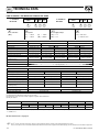
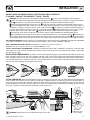
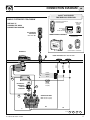
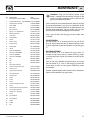
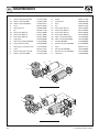
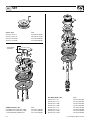
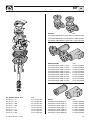
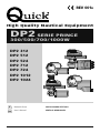
REV 001B
High Quality Nautical Equipment
DP2 SERIE PRINCE
300/500/700/1000W
DP2
DP2
DP2
DP2
DP2
DP2
DP2
312
512
524
712
724
1012
1024
IT
Manuale d'uso
SALPA ANCORA VERTICALI
GB
User's Manual
VERTICAL WINDLASSES
IT
INDICE
Pag. 4
Pag. 5
Pag. 6
Pag. 7
Pag. 8/10
Pag. 11
Pag. 12/13
GB
Caratteristiche tecniche
Installazione
Schema di collegamento 300/500W
Schema di collegamento 700/1000W
Manutenzione
Avvertenze importanti / Uso
Set
INDEX
Pag. 14
Pag. 15
Pag. 16
Pag. 17
Pag. 18/20
Pag. 21
Pag. 22/23
Technical data
Installation
Connection diagram 300/500W
Connection diagram 700/1000W
Maintenance
Warning / Usage
Set
DP2 300/500/700/1000W - REV001B
TECHNICAL DATA
GB
HOW TO IDENTIFY THE WINDLASS THROUGH THE CODE:
10
24
-
a
a
a
D
a
DP2
a
12
a
b
c
2° EXAMPLE:
DP21024
a
5
a
a
DP2
a
1° EXAMPLE:
DP2512D
d
a
b
c
d
c
b
Name of the line:
Motor power:
[ DP2 ]
[3]
[5]
[ 7 ] = 700 W
[ 10 ] = 1000 W
= 300 W
= 500 W
MODEL
MOTOR POWER
d
Motor supply voltage:
Drum:
[ 12 ] = 12 V
[ 24 ] = 24 V
[ D ] = with drum
[ - ] = without drum
DP2 – / D HI SPEED (4)
500W
DP2 – / D
300W
Motor supply voltage
500W
12V
12V
24V
12V
370 Kg (815,7 lb)
Maximum working load
120 Kg (264,5 lb)
200 Kg (441,0 lb)
220 Kg (485,0 lb)
170 Kg (374,8 lb)
200 Kg (441,0 lb)
40 Kg (88,2 lb)
65 Kg (143,3 lb)
70 Kg (485,0 lb)
65 Kg (143,3 lb)
70 Kg (154,3 lb)
65 A
80 A
40 A
100 A
50 A
Maximum chain speed (2)
29,2 (95,8 ft/min)
28,9 (94,8 ft/min)
28,2 (92,5 ft/min)
43,0 (141,1 ft/min)
42,5 (139,4 ft/min)
Maximum chain speed
@ working load (2)
24,4 (73,8 ft/min)
24,3 (59,7 ft/min)
24,1 (63,3 ft/min)
34,5 (93,5 ft/min)
35,0 (91,9 ft/min)
Working load
Current absorption @ working load (1)
660 Kg (1455,0 lb)
24V
Maximum pull
Deck thickness (3)
600 Kg (1322,8 lb)
20 ÷ 30 mm (25/32” ÷ 1” 3/16)
Weight modell without drum
9,8 Kg (21,6 lb)
Weight modell with drum
10,7 Kg (23,5 lb)
MODEL
MOTOR POWER
DP2 – / D
700W
Motor supply voltage
1000W
12V
Maximum pull
24V
12V
680 Kg (1499,1 lb)
24V
930 Kg (2050,3 lb)
Maximum working load
300 Kg (661,4 lb)
320 Kg (705,5 lb)
420 Kg (925,9 lb)
480 Kg (1058,2 lb)
Working load
100 Kg (220,5 lb)
107 Kg (235,9 lb)
140 Kg (308,6 lb)
160 Kg (352,7 lb)
95 A
50 A
130 A
75 A
Maximum chain speed (2)
22,6 (74,1 ft/min)
25,3 (83,0 ft/min)
31,2 (102,4 ft/min)
30,1 (98,7 ft/min)
Maximum chain speed
@ working load (2)
11,6 (38,1 ft/min)
14,4 (47,2 ft/min)
16,5 (54,1 ft/min)
19,1 (62,7 ft/min)
Current absorption @ working load (1)
Deck thickness (3)
25 ÷ 50 mm (63/64” ÷ 1” 31/32)
Weight modell without drum
15,6 Kg (34,3 lb)
16,7 Kg (36,8 lb)
Weight modell with drum
16,3 Kg (35,9 lb)
17,4 Kg (38,3 lb)
(1) After an initial period of use.
(2) Measurements taken with a gypsy for a 8 mm chain.
(3) On request, shafts and studs can be supplied for greater deck thicknesses.
(4) Only on request.
GYPSIES
Chain size
Rope size *
6 mm
6 mm
DIN 766
7 mm - 1/4”
6 mm
ISO**
1/2”
7 mm
DIN 766
7 mm
ISO**
1/2”
8 mm
1/4”
G4
1/4”
BBB
8 mm
DIN 766
1/2”
5/16”
8 mm
ISO**
1/2”
5/16”
G4
1/2”
* The values in the table refer to a three-strand polyester rope with a rope/chain splice manufactured with the “Quick®” system.
** ISO EN 818-3.
Models’ dimensions on page 26
F
14
Quick® reserves the right to introduce changes to the equipment and the contents of this manual without prior notice.
In case of discordance or errors in translation between the translated version and the original text in the Italian language, reference will be made to the Italian or English text.
DP2 300/500/700/1000W - REV001B
INSTALLATION
GB
BEFORE USING THE WINDLASS READ THESE INSTRUCTIONS CAREFULLY.
IF IN DOUBT, CONTACT YOUR NEAREST “QUICK®” DEALER.
WARNING: the Quick® windlasses are designed to weigh the anchor.
Do not use the equipment for other purposes.
Quick® shall not be held responsible for damage to equipment and/or personal injury, caused by a faulty use of the equipThe windlass is not designed for the loads that might occur in extreme weather conditions (storms).
ment.
Always deactivate the windlass when not in use.
Check that there are no swimmers nearby before dropping anchor.
The splice between the rope and the chain must be tightly woven for the rope to slide easily into the gypsy shape. For
®
For improved safety we recommend installing at
any problem or request, feel free to contact Quick Technical Service.
We recommend the use of the Quick® hydraulicleast two anchor windlass controls in case one is accidentally damaged.
Secure the chain with a further device before starting the navigation.
magnetic switch as the motor safety switch.
The contactor unit or reversing contactor unit must be installed in a point protected from accidental water contact.
After completing the anchorage, secure the chain or rope to fixed points such as chain stopper or bollard.
To prevent acciIsolate the windlass
dental releases, the anchor must be secured. The windlass shall not be used as the only securing device.
from the power system during navigation (switch the circuit breaker off) and lock the chain securing it to a fixed point of the boat.
THE PACKAGE CONTAINS: windlass (on deck unit + motorgearbox) - reversing contactor unit (300/500W), contactor unit (700/1000W)
- base gasket - drill template - handle - bolts and screws (for assembly) - user’s manual - conditions of warranty.
TOOLS REQUIRED FOR INSTALLATION: drill and drill bits: Ø 9 mm (23/64") and Ø 11 mm (7/16");
hollow mill: Ø 51 mm (2") and Ø 64 mm (2”1/2) ; hexagonal wrenche: 13 mm.
“QUICK®”ACCESSORIES RECOMMENDED: anchoring RL control board (mod. 800) - Waterproof hand helds R/C (mod. HRC1002)
- Foot switch (mod. 900) - Hydraulic-magnetic circuit breaker - Anchor chain counter (mod. CHC1102M and CHC1202M) - Radio control
RRC (mod. R02, PO2, H02).
INSTALLATION REQUIREMENTS: the windlass must be positioned with the gypsy aligned with the bow roller. Ensure that the
upper and lower surfaces of the deck are as parallel as possible. If this is not the case, compensate the difference appropriately (a
lack of parallelism could result in a loss of motor power). The deck thickness must be included among the figures listed in the table. In
cases of other thicknesses it is necessary to consult a Quick® retailer. There must be no obstacles under deck to the passage of cables,
rope and chain; lack of depth of the peak could cause jamming.
40 cm
(16”)
max
5 mm
(3/16”)
FITTING PROCEDURE: when the ideal position has been established, drill four holes using the drilling template provided.Remove
excess material from the chain passage, refine and flatten with a specialized product (marine paint, gel coat or two pack epoxy) to
assure free passage for both rope and chain. Position the upper section, inserting the gasket between the deck and the base and
connect the lower section to the assembly, inserting the shaft into the reduction unit. Fix the windlass by screwing the nuts onto the
fixing studs. Connect the supply cables from the windlass to the contactor unit.
45°
300/500W
700/1000W
WARNING: before wiring up, be sure the electrical cables are not live.
DP2 300/500/700/1000W - REV001B
Available motorgearboxes positioning
15
GB
CONNECTION DIAGRAM
QUICK® ACCESSORIES
FOR WINDLASS OPERATION
BASIC SYSTEM DP2 300/500W
WATERTIGHT HAND HELD
CHAIN COUNTER
SEE PAGE 24
SHOWING THE MAIN
CONNECTION DIAGRAM
WINDLASSES
CONTROL
BOARD
WATERTIGHT
PANEL
CHAIN COUNTER
MULTI-PURPOSE
WATERTIGHT HAND HELD
REMOTE CONTROL
MOD. HRC 1002
REMOTE RADIO CONTROLS
RECEIVER
TRANSMITTERS
RADIO POCKET - HANDHELD
WINDLASS
MOTOR
BLUE
BROWN
BLACK
FOOT SWITCHES MOD. 900U AND 900D
BLACK
BROWN
-
BLUE
+
BATTERY
FUSE
4A (12V)
2A (24V)
L1
HYDRAULICMAGNETIC
CIRCUIT
BREAKER
L2
L3
REVERSING
CONTACTOR UNIT
MOD. T6415-12 (12V)
MOD. T6415-24 (24V)
L4
L5
A1
C
A2
L = L1 + L2 + L3 + L4 + L5
16
DP2 300/500/700/1000W - REV001B
CONNECTION DIAGRAM
GB
QUICK® ACCESSORIES
FOR WINDLASS OPERATION
BASIC SYSTEM DP2 700/1000W
WATERTIGHT HAND HELD
CHAIN COUNTER
SEE PAGE 25
SHOWING THE MAIN
CONNECTION DIAGRAM
WINDLASSES
CONTROL
BOARD
WATERTIGHT
PANEL
CHAIN COUNTER
PULSANTIERA
MULTIUSO
MOD. HRC 1002
REMOTE RADIO CONTROLS
RECEIVER
TRANSMITTERS
RADIO POCKET - HANDHELD
WINDLASS
BLUE
MOTOR
BROWN
BLACK
FOOT SWITCHES MOD. 900U AND 900D
BLACK
BROWN
-
L4
BLUE
+
BATTERY
HYDRAULICMAGNETIC
CIRCUIT
BREAKER
L1
L3
FUSE
4A (12V)
2A (24V)
L2
L3
CONTACTOR UNIT
MOD. T6315-12 (12V)
MOD. T6315-24 (24V)
A2
C
A1
L = L1 + L2 + L3 + L4
DP2 300/500/700/1000W - REV001B
17
GB
MAINTENANCE
1
2
23
25
3
26
24
27
30
4
5
9
6
31
28
29
32
7
33
34
8
10
11
12
35
13
14
13
15
36
22
22
19
18
17
38
16
37
39
20
21
18
21
20
40
41
DP2 300/500/700/1000W - REV001B
MAINTENANCE
GB
WARNING: make sure the electrical power to the
motor is switched off when working manually on the
windlass. Carefully remove the chain or rope from the
gypsy or the rope from the drum.
POS. DESCRIPTION
CODE
1
Bent windlass lever 700-1000W
MSH0000000R1
2
Straight windlass lever - nylon 300-500W PVLVSDN00000
3
Drum bush DP2 chromed
SGMSD0400000
4
Drum - 800W
ZSPMSE0800R3
5
Gypsy cover
MSGB07GX0000
6
Top clutch cone
MSF07G000000
7
Gypsy” 5/16" complete DP2
ZSBDP20516R0
8
Bottom clutch cone
MSF08ASCN000
9
Screw 5*45
MBV0545MXCE0
10
Spring washer
MBR254010X00
11
Oil seal
PGPRL2547700
DRUM VERSION
12
Internal circlip
MBAN4717Y000
13
External circlip
MBAE2520Y000
14
Bearing 6005
MBJ600500000
15
Oil seal
PGPRL2540700
Use the handle (1 or 2) to loosen the bush (3); pull off the
drum (4) and the top clutch cone (6); loosen the fixing screws
(9) of the rope/chain stripper and remove it. Pull off the gypsy
(7).
16
Shaft DP2 700/1000W
MSASDP20L0R0
17
Shaft DP2 D 700/1000W
MSASDP2DL0R0
18
Shaft DP2 300/500W
MSASDP20S0R0
19
Shaft DP2 D 300/500W
MSASDP2DS0R0
20
Key
MBH0807080X0
21
Key
MBH0606050X0
22
Key
MBH0606025X0
23
Chain guide cover DP2
24
Plastic chain pipe series DP2
PDNCDP20000
25
Screw 3,9*25
MBV03925AXCC
26
Spring for pressure lever
MMTND08ASC00
27
Pressure lever DP2
PDLVTDDP2N00
28
Cylindrical pin
MBSC04040A00
29
Screw
MBV0416MXCEB
30
Screw
MBV0440MXCE0
31
Screw
MBV0430MXVEP
32
Plastic chain pipe series DP2
PDPS0DP20R01
33
Screw
MBV0814MXTSC
34
Stainless steel cover base serie DP2
MSGB0DP2X000
35
Plastic cover insert DP2
PDNC0DP20000
36
Gasket/ DP2 - shaped jig
PGBSDP200000
37
Sensor
KNREEDCL0000
38A
Stud 8*060 Ø8
MBP080608X00
38B
Stud 8*080 Ø8
MBP080808X00
39
Washer
MBR08X000000
40
Grower
MBR08XDE0000
41
Nut
MBD08MXEN000
DP2 300/500/700/1000W - REV001B
-
Quick® windlasses are manufactured with materials resistant
to marine environments. In any case, any salt deposits on the
outside must be removed periodically to avoid corrosion and
damage to the equipment. The parts where salt may have
built up should be washed thoroughly with fresh water.
Once a year, the drum and the gypsy are to be taken apart
as follows:
NO-DRUM VERSION
Use the handle (1 or 2) to remove the gypsy cover (5);
remove the top clutch cone (6); loosen the fixing screws
(9) of the rope/chain stripper and remove it and pull off the
gypsy (7).
Clean all the parts removed to avoid corrosion, and grease
the shaft thread (16, 17, 18 or 19) and the gypsy (7) where the
clutch cones (6 and 8) rest (use grease suitable for marine
environment).
Remove any oxide deposits from the terminals of the electric
motor and the contactor unit; grease them.
19
GB
MAINTENANCE
42
Gearbox flange gasket TOP TG40
PGFLRDTG4000
55
Washer
MBR061815X00
43A
Gearbox - Quick TG40 500W
SLMR05TG4000
56
Self locking nut
MBD06MXET000
43B
Gearbox - Quick TG40 500W HS
SLMR05TG40HS
57
O-ring
PGR023000000
44
Screw
MBV0516MXE00
58
Key
MBH050515F00
45
Geared motor seal
PGBMR0400000
59A
Electric motor 700w 12v
EMF071200000
46
Key
MBH040415F00
59B
Electric motor 1000w 12v
EMF101200000
47A
Electric motor 300W 12V
EMF031200000
59C
Electric motor 700w 24v
EMF072400000
47B
Electric motor 500W 12V
EMF051200000
59D
Electric motor 1000w 24v
EMF102400000
47C
Electric motor 500W 24V
EMF052400000
60A
Motor casing watertight 700w
PCCCPM070000
48
Flange gasket
PGGPMFN04000
60B
Motor casing watertight 1000w
PCCCPM100000
49
Motor casing watertight 300/500W
PCCCPM040000
61
Grommet 700/1000w
PCGPMMR00000
50
Poles gasket electric motor
PGGPMPM04000
62
Terminal board cover 700/1000w
PCCPPMMR0000
51
Bottom protec cover electric motor
PCCPPMFN0400
63
Screw
MBV02213AXSC
52
Screw
MBV03916AXCC
64
Bottom gasket 700/1000w
PGGPMFN00000
53
Gearbox flange gasket TOP TG50
PGFLRDTG50000
65
Bottom protec cover 700/1000w
PCCPPMFN0000
54
Gearbox - Quick TG50 1000W
SLMR10TG5000
66
Cable outlet
PPM20B000000
47
46
42
51
45
52
43
50
44
49
48
MOTORGEARBOX 300/500W
59
58
65
53
63
64
54
66
63
57
62
56
55
60
61
MOTORGEARBOX 700/1000W
20
DP2 300/500/700/1000W - REV001B
WARNING - USAGE
GB
WARNING
WARNING: stay clear of the chains, ropes and gypsy. Make sure the electric motor is off when windlass is used manually (even when using the handle to disengage the clutch). In fact people with windlass remote controls (hand-held remote control or radio-controlled systems) might accidentally operate it.
WARNING: secure the chain with a device before starting the navigation.
WARNING: do not operate the windlass by using the electrical power when the handle is inserted in the drum or into
the gypsy cover.
WARNING: Quick® recommends using a protection to prevent the engine line from suffering damages due to overheating or shortcircuits. For AC currents the use of a fuse is recommended (details on its dimension are specified in the page
of the connection diagram); For DC currents the use of a specific and delayed-action (thermal-magnetic or hydraulicmagnetic) circuit breaker is recommended. The circuit breaker can be used to cut off power to the windlass control
circuit and so avoid accidental activation.
CLUTCH USE
The clutch (6 and 8) provides a link between the gypsy (7) and the main shaft (16, 17, 18 or 19). The clutch can be released (disengagement) by using the handle (1 or 2) which, when inserted in the bush (3) of the drum (4) or into the gypsy cover (5), must
be turned counter-clockwise. The clutch will be re-engaged by turning it clockwise (engagement).
WEIGHING THE ANCHOR
Turn on the engine. Make sure the clutch is engaged and remove the handle (1 or 2).
Press the UP button on the control provided.
If the windlass stops and the hydraulic magnetic switch (or thermal cutout) has not tripped, wait a few seconds and try again
(avoid keeping the button pressed).
If the hydraulic magnetic switch, has tripped, reset it and wait a few minutes before weighing anchor once again.
If, after a number of attempts, the windlass is still blocked, we suggest to move the boat to release the anchor.
Check the upward movement of the chain for the last few meters in order to avoid damages to the bow.
CASTING THE ANCHOR
The anchor can be cast by using the electrical control or manually. To operate manually, the clutch (6 and 8) must be disengaged allowing the gypsy (7) to revolve and letting the rope or chain fall into the water.
To slow down the chain, the handle (1 or 2) must be turned clockwise.
To cast the anchor by using the electrical power, press the DOWN button on the control provided. In this manner, anchor casting is under control and the chain and rope unwind evenly.
In order to avoid any stress on the windlass -once the boat is anchored- fasten the chain or secure it in place with a rope.
DP2 300/500/700/1000W - REV001B
21
GB
SET
GYPSY - DP2
CODE
OSP GYPSY
OSP GYPSY
OSP GYPSY
OSP GYPSY
FVSSBDP20140A00
FVSSBDP20516A00
FVSSBDP20600A00
FVSSBDP20800A00
DP2 1/4”
DP2 5/16”
DP2 6MM
DP2 8MM
* CHAIN GUIDE
COVER KIT
COMPLETE BASE - DP2
CODE
OSP WINDLASS BASE SERIE DP2 L COMP
OSP WINDLASS BASE SERIE DP2 S COMP
FVSSBDP2LC00A00
FVSSBDP2SC00A00
FVSSCPSCDP20A00
* OSP CHAIN GUIDE COVER KIT DP2
22
TOP WITH DRUM - DP2
CODE
OSP TOP DP2 D L 1/4”
OSP TOP DP2 D L 5/16”
OSP TOP DP2 D L 6MM
OSP TOP DP2 D L 8MM
OSP TOP DP2 D S 1/4”
OSP TOP DP2 D S 5/16”
OSP TOP DP2 D S 6MM
OSP TOP DP2 D S 8MM
FVSSTDP2DL01A00
FVSSTDP2DL05A00
FVSSTDP2DL06A00
FVSSTDP2DL08A00
FVSSTDP2DS01A00
FVSSTDP2DS05A00
FVSSTDP2DS06A00
FVSSTDP2DS08A00
DP2 300/500/700/1000W - REV001B
SET
GB
CODE
GEARBOX
OSP GEARBOX 500W WINDLASS QUICK TG40 FVSSMR05TG40A00
OSP GEARBOX 500W WINDLASS QUICK TG40 HSFVSSMR0540HSA00
OSP GEARBOX 1000W WINDLASS QUICK TG50 FVSSMR10TG50A00
TOP WITHOUT DRUM - DP2
OSP TOP DP2 L 1/4”
OSP TOP DP2 L 5/16”
OSP TOP DP2 L 6MM
OSP TOP DP2 L 8MM
OSP TOP DP2 S 1/4”
OSP TOP DP2 S 5/16”
OSP TOP DP2 S 6MM
OSP TOP DP2 S 8MM
DP2 300/500/700/1000W - REV001B
CODE
FVSSTDP20L01A00
FVSSTDP20L05A00
FVSSTDP20L06A00
FVSSTDP20L08A00
FVSSTDP20S01A00
FVSSTDP20S05A00
FVSSTDP20S06A00
FVSSTDP20S08A00
MOTORGEARBOX
CODE
OSP MOTORGEARBOX 300W 12V QUICK
OSP MOTORGEARBOX 500W 12V QUICK
OSP MOTORGEARBOX 500W 12V QUICK HS
OSP MOTORGEARBOX 500W 24V QUICK
OSP MOTORGEARBOX 500W 24V QUICK HS
OSP MOTORGEARBOX 700W 12V QUICK
OSP MOTORGEARBOX 700W 24V QUICK
OSP MOTORGEARBOX 1000W 12V QUICK
OSP MOTORGEARBOX 1000W 24V QUICK
FVSSR0312Q00A00
FVSSR0512Q00A00
FVSSR0512QHSA00
FVSSR0524Q00A00
FVSSR0524QHSA00
FVSSR0712Q00A00
FVSSR0724Q00A00
FVSSR1012Q00A00
FVSSR1024Q00A00
MOTOR
CODE
OSP WINDLASS
OSP WINDLASS
OSP WINDLASS
OSP WINDLASS
OSP WINDLASS
OSP WINDLASS
OSP WINDLASS
MOTOR 300W 12V
MOTOR 500W 12V
MOTOR 500W 24V
MOTOR 700W 12V
MOTOR 700W 24V
MOTOR 1000W 12V
MOTOR 1000W 24V
FVSSM0312000A00
FVSSM0512000A00
FVSSM0524000A00
FVSSM0712000A00
FVSSM0724000A00
FVSSM1012000A00
FVSSM1024000A00
23
24
BATTERY
C
A2
BLACK
150
CAN H
CAN L
CAN H
RED
CAN L
BROWN
CAN H
WHITE
BLUE
BLACK
L = L1 + L2 + L3 + L4 + L5
+
-
A1
REVERSING
CONTACTOR UNITS
MOD. T6415-12 (12V)
MOD. T6415-24 (24V)
BROWN
L5
L4
L3
GREEN
L2
L1
MOD. 900/U
UP
WATERTIGHT PANEL
CHAIN-COUNTER
MOD. CHC 1202 M
CAN L
HYDRAULIC
MAGNETIC
CIRCUIT
BREAKER
FUSE
4A (12V)
2A (24V)
MOD. 900/D
DOWN
FOOT SWITCH
WATERTIGHT HAND
HELD
CHAIN-COUNTER
MOD. CHC 1102 M
GREY
MOTOR
SENSOR
QUICK® WINDLASS
MAIN CONNECTION
DIAGRAM
WINDLASSES
CONTROL BOARD
MOD. 800
MULTI-PURPOSE
WATERTIGH
HAND HELD
REMOTE
CONTROL
MOD. HRC 1002
RADIO RECEIVER RRC
MOD. R02 (2CH)
UP
DOWN
+
-
BLUE
BROWN
BLACK
BLUE
BROWN
BLACK
UP
DOWN
SENSOR
BLUE
DP2 300/500/700/1000W - REV001B
DP2 300/500/700/1000W - REV001B
L3
C
L2
L1
L3
A2
FUSE
4A (12V)
2A (24V)
BROWN
BLACK
CAN L
CAN H
L = L1 + L2 + L3 + L4
150
WATERTIGHT PANEL
WINDLASSES
CHAIN-COUNTER CONTROL BOARD
MOD. CHC1202 M
MOD. 800
CAN H
A1
CONTACTOR
UNITS
MOD. T6315-12 (12V)
MOD. T6315-24 (24V)
MOD. 900/U
UP
GREY
RED
GREEN
BROWN
WHITE
BLUE
BLACK
HYDRAULIC
MAGNETIC
CIRCUIT
BREAKER
BATTERY
SENSOR
MOD. 900/D
DOWN
FOOT SWITCH
WATERTIGHT HAND HELD
CHAIN-COUNTER
MOD. CHC1102 M
CAN L
CAN H
L4
MOTOR
QUICK® WINDLASS
MAIN CONNECTION
DIAGRAM
MULTI-PURPOSE
WATERTIGH
HAND HELD
REMOTE
CONTROL
MOD. HRC1002
RADIO RECEIVER RRC
MOD. R02 (2CH)
UP
DOWN
+
-
BLUE
BROWN
BLACK
BLUE
BROWN
BLACK
UP
DOWN
SENSOR
+
-
CAN L
BLUE
25
68 (2 43/64)
146 (5 3/4)
68 (2 43/64)
78 (3 1/16)
78 (3 1/16)
156 (6 9/64)
155 (6 7/64)
82 (3 1/4)
82 (3 1/4)
139 (5 15/32)
326,5 (12 55/64)
68 (2 43/64)
85 (3 11/32)
68 (2 43/64)
85 (3 11/32)
78 (3 1/16)
78 (3 1/16)
122 (4 51/64)
122 (4 51/64)
82 (3 1/4)
82 (3 1/4)
139 (5 15/32)
139 (5 15/32)
26
139 (5 15/32)
141,5 (5 9/16)
DP2 - DIMENSIONI / DIMENSIONS mm (inch)
DP2 300W
DP2 500W
196 (7 23/32)
196 (7 23/32)
273 (10 3/4)
273 (10 3/4)
DP2 700W
DP2 1000W
196 (7 23/32)
196 (7 23/32)
344 (13 35/64)
DP2 300/500/700/1000W - REV001B
DP2
SERIE PRINCE
300/500/700/1000W
IT
Codice e numero seriale del prodotto
GB
Product code and serial number
R001B
QUICK® S.p.A. - Via Piangipane, 120/A - 48124 Piangipane (RAVENNA) - ITALY
Tel. +39.0544.415061 - Fax +39.0544.415047
www.quickitaly.com - E-mail: [email protected]