1
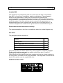
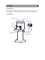
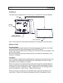
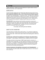
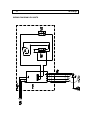
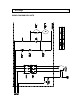
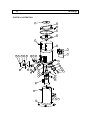
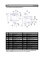
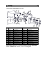
SP-RANGE INSTALLATION AND OPERATING MANUAL PLEASE LEAVE WITH OPERATOR SP12 & SP25 – SERIES 4 Imperial Machine Company Limited Unit 1, Abbey road Wrexham Industrial Estate Wrexham, LL13 9RF Tel: +44 (0)1978 661155 Fax: +44 (0)1978 729990 Service Fax: +44 (0)1978 667766 Spares Fax: +44 (0)1978 667759 E-mail: [email protected] Website: www.imco.co.uk A34/013 R12 ECN 7950 Jan 2013 SP-Range EC DECLARATION OF CONFORMITY (Guarantee of Production Quality) We, Imperial Machine Company Limited of: Unit 1, Abbey Road, Wrexham Industrial Estate, Wrexham, LL13 9RF Declare under our sole responsibility that the machine SP12 & SP25 SERIES 4 As described in the attached technical documentation is in conformity with the Machine Safety Directive 98/37/EC and is manufactured under quality system BS EN ISO 9001. It is also in conformity with the protection requirements of the Electro Magnetic Compatibility Directive 2004/108/EEC and is manufactured in accordance with harmonised standards EN 61000-6-1 Immunity and EN 61000-6-3 Emissions (plus product specific standards). It also satisfies the essential requirements of the Low Voltage Directive 2006/95/EC and is manufactured in accordance with harmonised standard EN 60204-1 Safety of Machinery (Electrical Equipment). Approved by S Witt, Engineering Manager Signed at Wrexham, Jan 2013 SP-Range INDEX GUARANTEE ....................................................................................................... 1 DELIVERY ............................................................................................................ 1 SAMPLE RATING LABEL ................................................................................... 1 INTRODUCTION .................................................................................................. 2 YOUR PEELER .................................................................................................... 2 CONTROLS .......................................................................................................... 3 INSTALLATION.................................................................................................... 3 WATER SUPPLY ................................................................................................. 4 WASTE OUTLET CONNECTION......................................................................... 4 WASTE EJECTOR ............................................................................................... 5 Fitting the waste ejector ................................................................................. 5 Waste Ejector adjustments ............................................................................ 5 ELECTRICITY SUPPLY CONNECTION .............................................................. 6 COMMISSIONING ................................................................................................ 7 OPERATION......................................................................................................... 7 SAFETY ................................................................................................................ 8 CLEANING ........................................................................................................... 8 DO’S AND DON’TS .............................................................................................. 9 MATERIAL CONTENT ......................................................................................... 9 MAINTENANCE ................................................................................................. 10 ORDERING SPARE PARTS .............................................................................. 10 WIRING DIAGRAM 1PH UNITS ......................................................................... 11 WIRING DIAGRAM 3PH UNITS ......................................................................... 12 PARTS ILLUSTRATION..................................................................................... 13 SPARES PART LIST .......................................................................................... 14 1PH CONTROL BOX SPARE PARTS LIST ...................................................... 15 3PH CONTROL BOX SPARE PARTS LIST ...................................................... 16 SP-Range 1 SP-Range GUARANTEE This equipment is guaranteed by IMC for 2 years from the date of its purchase from IMC, or from one of its stockists, dealers or distributors. The guarantee is limited to the replacement of faulty parts or products and excludes any consequential loss or expense incurred by purchasers. Defects which arise from faulty installation, inadequate maintenance, incorrect use, connection to the wrong electricity supply or fair wear and tear are not covered by the guarantee. Any damages/shortages must be reported to IMC within 24 hours of accepting delivery. No claims for damages will be considered if the goods have been onward delivered by you. Please observe these instructions carefully. The guarantee applies in this form to installations within the United Kingdom only. DELIVERY The packaged machine consists of: Peeler Unit, with lid, control box and mounting bracket 1 Peeling plate 1 Water supply pipe and 2 hose clips 1 1m long 3” flexible waste hose and hose clip 1 Instruction Booklet 1 If any accessories have been ordered they will be supplied in separate packages. Please notify both the carrier and the supplier within three days of receipt if anything is missing or damaged. Check that the correct machine has been supplied and that the voltage, marked on the rating label, is suitable for the supply available. The rating label is located at the back of the cylinder near the supply cable inlet. SAMPLE RATING LABEL SP-Range 2 INTRODUCTION This machine is intended for peeling potatoes. Its use may be extended to other root vegetables. It is not recommended to use this machine for peeling onions. YOUR PEELER SPLASH COVER LID CONTROL BOX DOOR CHUTE DOOR HANDLE MOUNTING BRACKET WASTE OUTLET 3 SP-Range CONTROLS The peeler has a separate box for mounting on a wall bracket near the machine. TIMER ON/OFF BUTTON TIMER / MANUAL SELECTOR SWITCH WALL BRACKET Note: Control boxes for three phase machines have separate on and off buttons. INSTALLATION For the Installer: These Instructions contain important information designed to help the user obtain the maximum benefit from the investment in an IMC SP Peeler. Please read them carefully before starting work, and consult with the supplier in the event of any queries. Be sure to leave this Instruction Manual with the user after the installation of the machine is complete. Procedure: The SP Range is supplied with a pedestal and is designed to be bolted to the floor. The control box is designed to be mounted on a wall bracket so that it is easily accessible once the machine is installed. Place the machine in its desired location and mark though the pedestal base the location of the five floor fixing holes. Remove the machine and prepare the floor for rawlbolts or other suitable floor fixings. Replace the unit into working position and fit the rawlbolts or other fixings. Tighten up the fixings. Place the control box bracket in the desired location and mark though the four screw holes. Remove the bracket and prepare the wall for rawlplugs or other SP-Range 4 suitable wall fixings. Replace the bracket and secure in place with four screws. Slide the control box onto its wall bracket. WATER SUPPLY Connect the water supply pipe to the water inlet located on the top of the lid, and secure using the supplied hose clips. Fit the other end of the supply pipe to a cold water supply that incorporates a tap or shut off valve that can be used to regulate the water flow to approximately 3 – 4 litres per minute. The water inlet is fitted with a baffle to improve the distribution of water into the cylinder. This may cause minor splashing on the surface of the lid; if this becomes severe, reduce water flow as required. The maximum water pressure for the supply is 10 bar. Ensure that the hose supplied with the machine is used and that an old hose is not reused. PLEASE NOTE: these machines are fitted with an air-break to prevent back syphonage into the mains supply. Some local authorities may nevertheless require connection is made to a storage cistern rather than direct to the mains supply. This applies to UK installations only. Overseas customers should install the machine in accordance with local regulations. If in doubt, check with your local authority WASTE OUTLET CONNECTION The peeler has two possible waste outlet locations. If it is required to change the waste outlet location, remove both the existing waste outlet and the blanking plate on the opposite side. Refit both the waste outlet and the blanking plate in their new positions. A flexible hose, supplied with the machine, can be fitted over the waste outlet to direct the waste into a gully or intercepting tank. If required, secure with the hose clip supplied. Longer lengths of flexible hose are available from IMC on request. The waste outlet also incorporates a 2” BSP female thread for connection to standard 54mm (2”) waste pipe. DO NOT reduce the diameter of the waste pipe to below 54mm. The length of the pipe should be kept to a minimum and the pipe must have a fall of at least 1:15. Changes of direction should be made by swept bends rather than elbows and cleaning eyes should be fitted where possible in accordance with standard plumbing practice. A trap is not necessary if the discharge is into a gully or an intercepting tank, although a trap must be provided in the outlet pipe from the intercepting tank. If a trap is required it should be made with 45° bends and not with a ‘U’ or ‘P’ bend or with a bottle trap. 5 SP-Range WASTE EJECTOR The waste ejector is an optional fitting that dilutes the waste sludge to enable it to flow easily through the drains without fear of blockage. Waste Ejectors are not recommended in the follow circumstances; A pipe run exceeding 15m between the machine and main drain When a fall of 1:15 cannot be achieved When piping is exceptionally complex In any of the above cases an interceptor tank is recommended. Fitting the waste ejector If the waste ejector is not fitted to the peeler when it arrives, it can be fitted as follows: Remove the existing waste outlet. Decide on which side the outlet pipe is to be connected and, if necessary, remove the blanking plate and gasket from the alternative waste outlet position and refit to the other side. Fit the waste ejector and gasket in place of the waste outlet. The waste ejector has a ½” BSP connection for the water supply on each side of the unit. Select which is to be used for the water connection and utilise the plug for sealing off the other. Connect the hose between the connector at the top of the waste ejector and the water inlet on the peeler lid. Waste Ejector adjustments When the pipework is complete set the ejector adjustments to give the correct water flow though the machine. Two adjusting screws and lock nuts are provided for this purpose. The top one controls flow though the peeler and the lower one controls the jet to the waste pipe. Adjust the top screw until the flow through the machine is between 2.25 and 7 litres per minute, then tighten the lock nut. Set the lower screw to allow a jet of water into the waste pipe of 2.25 to 3.5 litre per minute, then tighten the lock nut. SP-Range 6 ELECTRICITY SUPPLY CONNECTION Before connecting, examine the rating plate attached to the machine to ensure that the characteristics shown are correct for the supply available. Any changes to the supply or new mains runs should be carried out by a qualified electrician and in accordance with the IEE Codes of Practice. Single phase machines come supplied with a three pin plug. The socket used should be away from any splash area and be accessible with the peeler installed. A dedicated supply to the socket is recommended and it should be protected by a C or D class circuit breaker rated at 10A for the SP12 and 16A for the SP25. Three phase machines should be connected to a 15A isolator providing at least 3mm separation in all poles. The isolator should be fused at 10A. The supply to the machine must also be protected by a 30mA RCD. The mains lead fitted to the machine is the minimum required for individual connection to the mains supply. Site conditions may vary with additional length of cable run, encapsulation in trunking, etc. being required. Should this apply, a qualified electrician must alter the lead in accordance with the IEE Codes of Practice. WARNING: This machine must be earthed The wires in the mains lead for single phase supply are coloured: Green and Yellow Brown Blue Earth Live Neutral The wires in the mains lead for three phase supply are coloured: Green and Yellow Brown Black Grey Earth Phase 1 Phase 2 Phase 3 The 3 phase machines do not have a neutral wire. If the supply has a neutral wire isolate it and only wire the unit to the 3 phases and earth. An Equipotential earthing point is located on the back of the cylinder near the cable outlet if equipotential bonding is required. Should the mains lead become damaged, it must be replaced by an IMC service agent or qualified electrician in order to avoid a hazard. 7 SP-Range COMMISSIONING After making the electrical connection, switch on the machine, and check that the direction of rotation of the peeling plate is CLOCKWISE when viewed from above. The direction of rotation of single phase units is set at the factory. If it is not rotating in the correct direction contact IMC. To change the direction of rotation of three phase units, switch off the machine, isolate the supply and interchange any two phase wires. OPERATION 1 Fit the peeling plate, ensuring that it is properly located on the drive shaft. 2 Measure out the potatoes into a container which holds a known measured weight of 12kg or 25kg depending on machine size. Check for stones which could damage the abrasive. Should this happen, the noise will indicate the presence of stones. Switch off immediately and remove them. The top of the liner can also be used as a maximum loading line. 3 Set the run time required on the control panel - two minutes is normally more than adequate – or select manual operation, and press the green start button. Turn on the water supply. 4 Ensure that the chute discharge door is closed. 5 Load the potatoes into the peeler and place the splash cover onto the top of the cylinder. 6 The machine is now operating. Remove the splash cover to check the progress of peeling process. 7 The peeler can be stopped at any time by pressing the Stop button, or it will stop on completion of a timed cycle. 8 Turn off the water supply, open the chute door and while keeping the door open, press the Start button to evacuate the potatoes, press the Stop button when the peeler is empty. 9 Keep the peeled potatoes under water until required for cooking. ON NO ACCOUNT put a hand or implement into the machine, or wedge the door open while discharging. SP-Range 8 SAFETY All SP-Range peelers are controlled so that if the electricity supply is interrupted the machine will not restart automatically. All single phase SP-Range controls are fitted with a thermal trip. This ensures that the controls cannot overheat and become damaged. If the thermal trip cuts in, the machine will not run until it has cooled down and the peeler is switched off and on again. The controls will not overheat in normal usage. Do not put hands into the machine while it is running. On single phase machines do not unplug the unit with wet hands. CLEANING It is essential to clean the machine at least once a day, preferably at the end of each period of operation. 1 2 3 4 5 6 Switch off at the socket or isolator. Remove the lid and splash cover. Lift out the peeling plate. Clean the peeling plate and cylinder in a sink, potwash or by hosing with a spray. Rinse the inside of the peeling chamber and base with warm water, using a mild detergent if necessary to remove starch build up. Wipe the exterior of the machine with a damp cloth, again using a mild detergent if required. DO NOT USE CLEANING MATERIALS CONTAINING ABRASIVES OR BLEACHES. DO NOT STEAM CLEAN. DO NOT CLEAN WITH A WATER JET. 9 SP-Range DO’S AND DON’TS Do Do Do Don’t Don’t Don’t Install on a level service. Ensure power supply isolator or socket is accessible with the peeler installed. Clean the machine after each period of use. Sit or stand on top of the peeler. Place hands inside unit while discharging or peeling. Use the unit outside. MATERIAL CONTENT The SP-Range peelers contain the following materials: Metals Stainless steel, Mild steel (inc plated), Aluminium and copper. Plastics and rubber Polycarbonate, Nylon, Neoprene rubber. Other Aluminium oxide, electrical components. SP-Range 10 MAINTENANCE Other than regular cleaning the SP-Range of peelers require no maintenance by the end user. It is recommended that the unit is serviced by an IMC approved engineer at least once a year. The motor in the single phase units is controlled via an inverter. The following warnings must be observer before working on this unit. WARNING. Only suitably qualified personal should service this equipment, after becoming familiar with all safety notices, installation, operation and maintenance procedures related to the inverter. WARNING. Risk of electric shock. The capacitors in the inverter remain charged for 5 minutes after power has been removed. Do not open the control box until 5 minutes after power has been removed. WARNING. Repairs to the inverter may only be carried out by Schneider Service, or by repair centres authorised by Schneider. Details of IMC Service Contracts are available on application. ORDERING SPARE PARTS In the event that spare parts or accessories need to be ordered, please always quote the SERIES AND SERIAL NUMBER of the machine. This is to be found on the rating plate located near the supply cable. For installations outside the UK please contact your supplier. For information on IMC spares and service support (if applicable), please call IMC on +44 (0)1978 661155. Alternatively, contact us via email or fax: IMC Service Desk Fax: +44 (0)1978 667766 E-mail: [email protected] IMC Spares Desk Fax: +44 (0)1978 667759 E-mail: [email protected] 11 WIRING DIAGRAM 1PH UNITS SP-Range SP-Range WIRING DIAGRAM 3PH UNITS 12 13 SP-Range PARTS ILLUSTRATION 34 32 33 31 30 19 29 28 27 19 20 21 22 23 24 25 26 15 14 13 12 8 16 18 8 11 17 7 9 8 10 7 9 7 6 2 3 1 4 5 SP-Range 14 SPARES PART LIST SP12 SP25 Item Part No Description Part No Description 1 S58/593 S58/594 D18/050 D20/038 D25/004 G60/369 G40/205 G60/372 G60/373 G86/003 D18/050 D25/079 D25/068 S58/549 A02/070 C28/023 M1 Z2 SP12 Low Pedestal SP12 High Pedestal Screw M6 x 16 CSK SS M5 Full Nut SS M5 Shakeproof Washer SS Earth Wire, Motor to Pedestal Motorgearbox 0.37kW Motor cable (1ph) Motor cable (3ph) Ferrite (1ph only) M8 Full Nut SS M8 Spring Washer SS M8 Plain Washer SS Bearing Housing Assembly O Ring Waste Outlet, Machined SP25 Low Pedestal SP25 High Pedestal Screw M6 x 16 CSK SS M5 Full Nut SS M5 Shakeproof Washer SS Earth Wire, Motor to Pedestal Motorgearbox 0.75kW Motor cable (1ph) Motor cable (3ph) Ferrite (1ph only) M8 Full Nut SS M8 Spring Washer SS M8 Plain Washer SS Bearing Housing Assembly O Ring Waste Outlet, Machined E58/059 A11/026 G80/029 E58/081 D20/031 D25/052 D20/031 D25/005 M79 L21/048 D18/051 D21/057 S59/253 A00/058 E58/096 E58/111 S58/587 Waste Outlet Cover Plate Waste Outlet Gasket Cable Gland Chute Screw M6 x 12 Hex SS M6 Plain Washer SS M6 Dome Head Nut M6 Shakeproof Washer SS Door Roller Eccentric Screw M6 x 20 CSK SS Screw M8 x 20 Pan SS Door Handle Nylon Shoulder Washer Wall Bracket (1ph) Wall Bracket (3ph) SP12 Control Box 1ph (Inverter) (Inc. Wall Bracket & cables) SP12 Control box 3ph (Inc. Wall Bracket & cables) Mains cable and plug (1ph) Mains cable (3ph) SP12 Liner SP12 Peeler Plate SP12 Rim Moulding SP12 Cast Lid assembly (Including Spray Nozzle) Spray Nozzle SP12 Splash Cover S58/590 E58/591 D18/050 D20/038 D25/004 G60/369 G40/216 G60/372 G60/373 G86/003 D18/050 D25/079 D25/068 S58/549 A02/070 C28/023 M1 Z2 E58/059 A11/026 G80/029 E58/081 D20/031 D25/052 D20/031 D25/005 M79 L21/048 D18/051 D21/057 S59/253 A00/058 E58/096 E58/111 S58/588 2 3 4 5 6 7 8 9 10 11 12 13 14 15 16 17 18 19 20 21 22 23 24 25 26 27 28 S58/596 29 30 31 32 G60/370 M2 G60/371 E58/113 Z S58/545 M58/011 M1 S58/592 33 34 J04/324 S58/541 S58/595 G60/370 M2 G60/371 E58/114 Z S58/546 M58/011 M2 S58/589 J04/324 S58/542 Waste Outlet Cover Plate Waste Outlet Gasket Cable Gland Chute Screw M6 x 12 Hex SS M6 Plain Washer SS M6 Dome Head Nut M6 Shakeproof Washer SS Door Roller Eccentric Screw M6 x 20 CSK SS Screw M8 x 20 Pan SS Door Handle Nylon Shoulder Washer Wall Bracket (1ph) Wall Bracket (3ph) SP25 Control Box 1ph (Inverter) (Inc. Wall Bracket & cables) SP25 Control box 3ph (Inc. Wall Bracket & cables) Mains cable and plug (1ph) Mains cable (3ph) SP25 Liner SP25 Peeler Plate SP25 Rim Moulding SP25 Cast Lid assembly (Including Spray Nozzle) Spray Nozzle SP25 Splash Cover SP12 ACCESSORIES SP25 ACCESSORIES A29/003 S58/568 S58/569 S58/570 A29/003 S58/568 S58/569 S58/570 Splash Cover Retaining Strap Integral Filter Basket Floor Standing Interceptor Tank Waste ejector Splash Cover Retaining Strap Integral Filter Basket Floor Standing Interceptor Tank Waste ejector When ordering spare parts or accessories always quote the SERIES AND SERIAL NUMBER of the machine, found on the rating label. 15 SP-Range 1PH CONTROL BOX SPARE PARTS LIST 8 7 13 2 14 3 1 6 9 15 16 17 4 5 10 20 19 12 21 11 21 SP12 SP25 Item Part No Description Part No Description 1 E58/096 E58/097 G76/031 M2 D21/052 A08/641 E58/116 G30/431 M1 E58/096 E58/097 G76/031 M2 D21/052 A08/641 E58/116 G30/431 M2 D25/033 D21/038 A10/224 G80/029 G60/372 G60/370 M2 G34AL A11/219 D25/066 D21/031 G45/066 Mounting Bracket Wall Bracket (Not shown) Control Box Screw M6 x 16 Pan SS Decal Control Box Plate Programmed Inverter 0.75kW (Schneider) M4 Shakeproof Washer SS Screw M4 x 12 Pan SS Cable Gland Nut Cable Gland Motor cable 1ph Mains cable and plug1ph Timer Timer Gasket M3 Seloc Washer Screw M3 x 8 Pan SS Timer Knob D25/033 D21/038 A10/224 G80/029 G60/372 G60/370 M2 G34AL A11/219 D25/066 D21/031 G45/066 Mounting Bracket Wall Bracket (Not shown) Control Box Screw M6 x 16 Pan SS Decal Control Box Plate Programmed Inverter 0.75kW (Schneider) M4 Shakeproof Washer SS Screw M4 x 12 Pan SS Cable Gland Nut Cable Gland Motor cable 1ph Mains cable and plug1ph Timer Timer Gasket M3 Seloc Washer Screw M3 x 8 Pan SS Timer Knob G45/113 G45/114 G45/111 Push Button Black Selector Switch Button contacts and holder G45/113 G45/114 G45/111 Push Button Black Selector Switch Button contacts and holder 2 3 4 5 6 7 8 9 10 11 12 13 14 15 16 17 18 19 20 21 When ordering spare parts or accessories always quote the SERIES AND SERIAL NUMBER of the machine, found on the rating label. SP-Range 16 3PH CONTROL BOX SPARE PARTS LIST 1 3 13 4 14 5 10 11 15 16 17 8 2 6 9 7 12 18 SP12 19 SP25 Item Part No Description Part No Description 1 2 3 4 5 6 7 8 9 10 11 12 13 14 15 16 17 18 19 20 E58/117 E58/119 G76/041 M1 D21/097 E58/118 A10/224 G80/029 D25/004 D20/038 G30/316 D22/022 G30/318 G34AL A11/219 D25/066 D21/031 G45/066 G45/099 G45/100 G45/102 G60/371 G60/373 Mounting Bracket Wall Bracket Control Box (inc lid) Screw M4 x 8 Pan SS Control Box Plate Cable Gland Nut Cable Gland M5 Shakeproof Washer M5 Full Nut SS Contactor 400V (3ph) Screw No8 x ½” Overload (3ph) Timer Timer Gasket M3 Seloc Washer Screw M3 x 8 Pan SS Timer Knob Green Push Button Red Push Button Selector Switch Mains supply cable 3ph Motor cable 3ph E58/117 E58/119 G76/041 M1 D21/097 E58/118 A10/224 G80/029 D25/004 D20/038 G30/316 D22/022 G30/299 G34AL A11/219 D25/066 D21/031 G45/066 G45/099 G45/100 G45/102 G60/371 G60/373 Mounting Bracket Wall Bracket Control Box (inc lid) Screw M4 x 8 Pan SS Control Box Plate Cable Gland Nut Cable Gland M5 Shakeproof Washer M5 Full Nut SS Contactor 400V (3ph) Screw No8 x ½” Overload (3ph) Timer Timer Gasket M3 Seloc Washer Screw M3 x 8 Pan SS Timer Knob Green Push Button Red Push Button Selector Switch Mains supply cable 3ph Motor cable 3ph When ordering spare parts or accessories always quote the SERIES AND SERIAL NUMBER of the machine, found on the rating label. 20