1
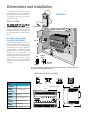
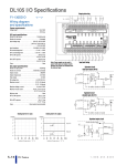
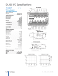
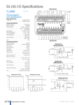
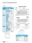
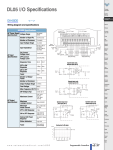
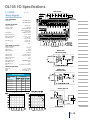
Dimensions and Installation
It is important to understand the installation requirements for your DL105 system.
This will help ensure that the DL105 products operate within their environmental
and electrical limits.
Installation
Plan for safety
This catalog should never be used as a
replacement for the user manual. The user
manual, D1-USER-M, contains important
safety information that must be followed.
The system installation should comply with
all appropriate electrical codes and standards.
Unit dimensions and
mounting orientation
Use the following diagrams to make sure
the DL105 system can be installed in your
application. DL105 units must be mounted
horizontally to ensure proper airflow for
cooling purposes. It is important to check
these dimensions against the conditions
required for your application. For
example, we recommend that you leave 2"
depth for ease of access and cable clearance; however, your distance may be
greater or less. Also, check the installation
guidelines for the recommended cabinet
clearances.
Temperature probe
2"
50mm
min
Power source
2"
50mm
min
2"
50mm
min
Panel ground terminal
Bus b
ar
Panel
Earth
ground
Ground braid
copper lugs
Panel or single
Point ground
Star washers
Note: There is a minimum of 2" (50mm) clearance required between the panel door or any devices mounted in
the panel door and the nearest DL105 component.
Dimensions and mounting
Environmental Specifications
Storage
Temperature
Ambient
Operating
Temperature
Ambient
Humidity
Vibration
Resistance
Shock
Resistance
Noise
Immunity
Atmosphere
-4ºF to 158ºF (-20ºC to 70ºC)
32ºF to 131ºF (0º to 55ºC)
Units: inches(mm)
3.48
(88.3)
5.12
(129.9)
30% to 95% relative humidity (noncondensing)
MIL STD 810C, Method 514.2
MIL STD810, Method 516.2
NEMA(ICS3-304)
No corrosive gases
3.16
(80.3)
3.63
(92.1)