1
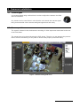
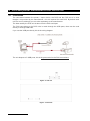
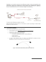
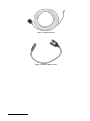
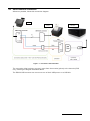
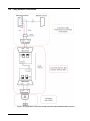
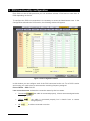
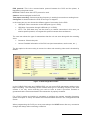
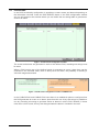
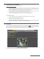
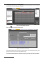
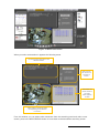
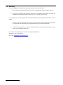
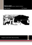
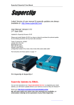
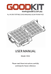
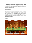
POS UNITS Count, video recording and POS control unit ENGLISH Installation and user guide INDEX 1 2 3 FUNCTIONALITY .................................................................................................................................... 2 GENERAL CONSIDERATIONS .............................................................................................................. 4 CAMERAS INSTALLATION ................................................................................................................... 5 3.1 CAMERA TYPES ................................................................................................................................. 5 3.2 CAMERA POSITION ............................................................................................................................. 5 4 POS AND PRINTER CONNECTION TO THE PECO-POS .................................................................... 6 4.1 CONNECTION..................................................................................................................................... 6 4.2 CONNECTION ELEMENTS .................................................................................................................... 7 4.3 SHORT DISTANCE CONNECTION .......................................................................................................... 9 4.4 LONG DISTANCE CONNECTION .......................................................................................................... 10 5 POS FUNCTIONALITY CONFIGURATION .......................................................................................... 12 5.1 POS EVENTS................................................................................................................................... 14 5.2 CHECKING THE POS INSTALLATION .................................................................................................. 15 5.3 LIVE VIDEO ...................................................................................................................................... 15 5.4 INFORMATION SEARCH IN RECORDING VIDEO ..................................................................................... 16 5.5 ANOMALY ........................................................................................................................................ 18 6 APPENDIX 1 – TECHNICAL SPECIFICATIONS ................................................................................. 19 User manual 1 1 Functionality A unit with POS function can link images to the data generated by the sales terminal, both live video and recording video. The POS functionality is available for local and remote interface. The units are compatible with the Supervisor VS only for video functionality and with PeCo-Graph for counting functionality. Images associated with POS One of the main features is the data and image searching concurrently on all cameras associated to the POS system. The searching can cover different days, you have to enter the cash ticket data or request an intelligent word search. The storage of the data that is generated by the sales terminal besides the recording video allows you to export video synchronized with the data. Models There are several models of units with POS functionality: VX4BOX-POS: 4 cameras compact video recorder VX8BOX-POS: 8 cameras compact video recorder. VX8-POS: 8 cameras video recorder. VX8-PeCo-POS: 8 cameras video recorder with PeCo functionality. VX16-PeCo8-POS: 16 cameras video recorder with PeCo functionality. Check the model in the front label or in the one placed on the bottom of the computer. Connections The POS connections are made through the unit’s USB ports, or through external 4 ports hubs connected to the USB unit ports, In case you use hubs for the connections all the POS must be connected through them. VX4BOX-POS: up to 4 POS connections, directly connected to the unit or through one hub. VX8BOX-POS: up to 8 POS connections, through one or two USB hubs. VX8POS / VX8-PeCo-POS: up to 8 POS connections through two hubs. VX16-PeCo-POS: up to 16 POS connections through four external hubs. User manual 2 Events and alarms Other feature is the ability to define a list of words or strings common to all POS to generate events, and another to generate alarms. With the events and alarms you can mark the video, generate relay activations and send alarms. The alarms can be sent via e-mail (alarm frames: VAV) or can be notified to up to two Supervisor VS. Events and alarms in VX4BOX-POS and VX8BOX-POS units In these units apart from the use of key text strings, is possible to use any incoming text string to generate events or alarms in all the POS. The alarms sent by e-mail contain the key text that generates the POS alarm in the subject’s mail. Additional functionality Besides its functionality as POS unit, several units have functionality as PeCo unit, and can analyze images and provide people flow data. As video recording unit has real time video recording with data transmission to one or several users. For further information about these features please consult VX4BOX/VX8BOX/VX4/VX8/VX16 video recording manual and the PeCo user manual. the User manual 3 2 General considerations Connection types on the POS. A. Serial port POS connection. 1.- The POS has to send out the data always by the serial port and it has to be configured as follows: .- Bits per second: 9600 .- Data bits: 8 .- Parity: None .- Stop bits: 1 .- Flow control: None 2.- The printer or output device is independent of the POS unit. It must have a serial port this way you can use the supplied cable. 3.- Before you install a unit with POS functionality, consult your distributor or the manufacturer the compatibility whit the POS and the printer or output device: it must be in the list of compatible protocols for the POS unit. 4.- In case of not being compatible in the date of the consult, Visual Tools reserves the right to adapt the printer in the time-frame it deems appropriate. 5.- The data line is ONE WAY, meaning that the POS (point of sale) sends the information, and both printer and POS unit receive it. 7.- You have to use always the supplied cable even if you use the RS232-485 converters option for long distances. B. HTTP POS connection 1.- The POS cable it is not necessary, the connection is being made through a network cable between the POS and the unit. 2.- The POS must have integrated the data transmission protocol supplied by the manufacturer of the POS units. 3.- The unit has a specific key for this protocol, the POS must have this key configured to communicate. 4.- The POS has an ID that has to be defined in the POS unit, in the Configuration / POS screen. User manual 4 3 Cameras installation 3.1 Camera types It is recommended using varifocal lens in order to adjust the cameras view field after its installation. Any camera can be used. Bear in mind that the unit records the camera signal, being recommended colour cameras with good signal level and clarity. 3.2 Camera position The system is based in the simultaneous recording of video sequences associated to the text of the POS ticket. The camera has to be placed showing the POS image. The aim is to see properly the product that is sold but sometimes you can prefer to observe the people (consult the client). Figure.- 1 Camera showing POS vision User manual 5 4 POS and printer connection to the PeCo-POS 4.1 Connection The connection between the printer / output device, the POS and the POS unit it is done thought a kit provided by the manufacturer, a kit it’s required for each POS. By default each unit has one kit, although you can order separately to the manufacturer. The data used by the POS unit is taken from the POS serial port. The POS connection to the POS units is made through the USB ports, there can be used directly or through USB hubs. If you use the USB port directly this is the wiring diagram: The unit dispose of 6 USB ports; this is the ports order for the POS connections: Figure.- 2 Unit rear Figure.- 3 Unit front User manual 6 Supposing you use hubs to connect to the USB ports, please use the ones provided by the manufacturer. You can use a maximum of 1 hub of 4 ports for the VX4BOX-POS, 2 hubs of 4 ports for the VX8BOX-POX, VX8-POS and VX8-PeCo8-POS units, and 4 hubs of 4 USB ports for the VX16-PeCo8-POS units. The connection diagram is the following: The order of the USB ports is marked in the hubs. When the POS uses HTTP protocol, the connection is made only through a network cable between the POS and the unit. 4.2 Connection elements First we have to distinguish all the connection parts: The POS (point of sell); IMPORTANT: Serial port, RS-232 protocol. The printer (or other device as appropriate). The POS unit with the cable that includes: o Connection cable between printer, POS and POS unit. o Signal extension. o RS232-USB converter. In case of long distances (over 10 meters) two RS232-485 converters and two DB9/DB25 converters (not provided by the manufacturer). Figure.- 4 Connection cable between printer, POS and POS unit User manual 7 Figure.- 5 Signal extension Figure.- 6 RS232 – USB converter User manual 8 4.3 Short distance connection Whenever possible, follow this connection diagram: POS Printer POS Unit Figure.- 7.- Connection with POS cable The connection (that is always one-way), goes from the encoder (printer) to the decoder (POS unit), following the diagram described above. The RS232-USB converter can connect to one of the 6 USB ports or to a USB hub. User manual 9 4.4 Long distance connection Figure.- 8- Long distance connection example with POS cable and RS232-485 converters User manual 10 When the distance is higher than the POS cable, the connection (that is always unidirectional) it’s made through the 485 protocol. So it is necessary to use two RS232 – 485 converters, these converters connect in one side the POS cable and in the other the RS232 converter to the USB, following the previous diagram that describes an example with ATEN IC 485 converters, although there can be used different models, these converters are not provided by the manufacturer. If it is necessary to use a DB9 to DB25 adapter please be sure that you don’t cross the signal. It the converter led is always on, that means the signal is crossed, change the place of the reducer or change the micro switch to DTE in the RS232 – 485 converters. There is another option to connect the 485 connection directly to USB with the ACKSYS US400 converter, for further information please consult the support department. By phone: 91 729 48 44 By e-mail: [email protected] User manual 11 5 POS functionality configuration Each POS unit has 6 USB ports and you can associate at least 4 POS and no more than 16 POS depending on the unit. To configure the POS unit connections it is necessary to access as Administrator user. In the Configuration tab select the POS section, the following window will appear. Figure.- 9 POS configuration window In this window you can configure each of the POS connected to the unit. For a POS is active and running you need to have a camera and a recording frequency assigned. Point of Sales – POS: POS ID. Last connection state: It shows the connection status by the icon status. Connected , the cable is connected properly, it has a camera assigned and a recording frequency. Offline the cable is connected properly but it doesn’t have a camera assigned or a recording frequency. Off User manual 12 is neither connected nor active. POS protocol: This is the communication protocol between the POS and the printer, is identified by the printer name. HTTP Id: POS ID when thee HTTP protocol is used. Camera: camera assigned to the POS. Time-lapse recording: Camera recording frequency in working hours and non working hours. Configured: It shows whether the POS is running or is stopped. In the lower part you can choose the different types of connection for the POS. USB ports. Direct connection to the USB ports (up to 6 POS). USB hubs. Connection through USB hubs (8 / 16 POS). HTTP. The POS data entry can be done by a network connection in this case you need a specific protocol, to integrate this protocol contact the manufacturer. The next item shows the type of transactions that the unit can store along with the recording video. Customer: Client ticket print. Journal: Detailed information of the POS use (card transactions, cash counts, etc..) The last option is the text overlay in remote live video and recording video and is checked by default. Figure.- 10 POS configuration window In the VX4BOX-POS units and VX8BOX-POS you can record POS transactions without timelapse recording. The Recording section shows what type of recording frequency has each camera. If it’s only event recording you need to have at least 2 pre-event seconds to guarantee that the video associated to the transaction is properly recorded. For a POS is active and working is necessary to configure the camera recording frequency (either time-lapse or event) and select the POS associated camera in the Configuration/POS screen. When programming the POS you must press always the SAVE button after any connection change and always after connecting a data line. User manual 13 5.1 POS events In the POS functionality configuration is possible to create events and alarms depending on the information received. Press the POS EVENTS button in the POS configuration window and you will access to this window where you can define the text strings able to generate an event or an alarm. Figure.- 11 POS events configuration window The events and alarms are generated in each of the defined POS, matching text strings must be exact. When a POS receive any of the defined words it generates an event / alarm than can be consulted in the recorded video, there is also just for an alarm, the possibility of sending a VAV with images associated. Figure.- 12 POS events configuration window in VXBOX units. In the VX4BOX-POS and VX8BOX-POS units there is an additional option to configure when the POS generates an event or an alarm. Apart from the use of key text strings is possible to use any incoming text string to generate events or alarms in all the POS. Besides, in these units when a VAV is sent, the key text that generates the alarm in included in the mail. User manual 14 5.2 Checking the POS installation Follow the next steps to check the POS working. Checking the data reception: 1. Issue a ticket in the checkout chosen as test and check that at this moment (most likely need two people is the location is not the same) there is a flashing light on the RS232 – USB converter, which is physically connected to the unit. 2. If this not happen, we have to check the line wiring. The best way is to check the continuity with a tester both the ground wire and the signal wire. 3. If there is a flashing light, that means the POS unit has received data. Visualization checking: 1. Connect remotely to the unit through an Internet Explorer or connect locally. 2. Log in with a user able to watch live video. 3. Select the camera associated to the POS. 4. Press the POS button to access the window where you can see the transactions received by the POS that it associated to the selected camera. 5.3 Live video In the live video screen, both local and remote you can watch the transactions that the POS is receiving, select the camera associated to the POS and press the icon, a new window will appear with the viewer transaction at the top and the video viewer on the bottom. Figure.- 13 POS live video screen To come back to the live video screen press the BACK button. User manual 15 5.4 Information search in recording video The information that the POS gets is associated to the recording video, you can access the recording video screen to search for transactions. Figure.- 14 POS recording video screen Pres in the icon to open the search screen. Figure.- 15 Transaction search screen Select the POS device where you want to make the search, set a starting and final date, write the text screen to search and press the SEARCH button. At the bottom window appears the transactions that match the searching text string. It appears in blue the transactions that can be selected, the ones in grey doesn’t have video associated. User manual 16 Figure.- 16 Search result screen When you select a transaction it appears the following areas. Transactions that takes place in the selected moment Data from the last search and new search button Test results: the results shown in the video viewer appears in black Video viewer it shows the video corresponding to the selected transaction From this window you can select other transaction from the searching panel and make a new search, press in the NEW SEARCH button to come back to the transaction searching screen. User manual 17 5.5 Anomaly If you find illegible text strings in the results, may be due to two reasons: 1. Error when selecting the POS protocol in the configuration window of the POS unit. 2. The POS is sending data from the serial port at a different speed from the POS unit standard. By default the speed is 9600, 8,n,1,n. Change it in the POS. If the POS button doesn’t appear but the RS232-USB converter led flashes when we issue a ticked. 1. Access to the POS configuration screen in the unit and check the protocol being used, the assigned camera and the recording frequencies. Pres the SAVE button. 2. If the problem persists, you have to restart the POS unit and do the test again, issue a ticket, go to recording video, etc.. For further information please contact the support department: By phone: +34 91 729 48 44 By e-mail: [email protected] User manual 18 6 Appendix 1 – Technical specifications MODELS: VX4BOX-POS: DVR of 4 cameras and 4 POS VX8BOX-POS: DVR of 8 cameras and 6/8 POS. VX8-POS: DVR of 8 cameras, 6/8 POS. VX8-PeCo-POS: DVR of 8 cameras, 8 counters and 6/8 POS. VX16-PeCo8-POS: DVR of16 camera , 8 counters and 6/16 POS. OPERATOR WORKSTATION: Local interface for a VGA monitor and for two CCTV monitors (except VXBOX units). Remote access via WEB browser from any PC with MS Internet Explorer or with the Supervisor VS reception and management software. Different user levels password-protected. Multiple user login. COMMUNICATION: Web server over TCP/IP with Ethernet internal adapter and RJ45 connector. Automatic management for Internet connections with dynamic IP address. Automatic time synchronisation with a configurable NTP Server. PEOPLE COUNTERS: For VX8-Peco8-POS and VX16-PeCo8-POS units. 8 independent people counters based on the video images analysis. Differentiation of simultaneous people flow. In and out counts for each counter. VIDEO INPUTS: PAL or NTSC video inputs (according to the model) with BNC connectors selectable 75 Ohms loads fro each signal, except for VXBOX units. ALARM INPUTS: 8 non-isolated inputs and 1 input for VXBOX units. For dry contacts. 1 switchable screw terminal female connector. Customisable alarm input titles and polarity inversion from the configuration interface. RELAY OUTPUTS: 4 relay outputs with NO/NC contacts and 1 for VXBOX units. 24V 1A switch power. 1 switchable screw terminal female connector. Manual activation by the operator or configurable to indicate POS event/POS alarm. Customizable relay output titles from the configuration interface. VIDEO OUTPUTS 1 VGA video output for local interface use 2 CCTV video outputs (PAL or NTSC according to the model) for cyclic visualisation of the active cameras and alarm monitoring, except VXBOX units. Control of the monitors from the local interface. POS TERMINAL CONNECTION: Connection of 4 POS terminals for VX4BOX-POS by using the USB unit ports or 1 hub. Connection of up to 6 POS terminals by using the USB unit ports and possibility of connecting up to 8 POS by installing 2 external 4 ports USB hubs (for VX8BOX-POS, VX8-PeCo8-POS and VX8-POS) and 16 POS by installing 4 ports USB hubs for VX16-PeCo8-POS units. If using hubs, all POS must be connected through them. The connection to the POS must be made by using a kit that includes a USB adapter to RS232 port. One kit per POS. The POS data are retrieved from the serial port. In most cases, existent printer connection socket is used. Please consult available protocols. RECORDING OF TRANSACTIONS: Recording of transactions from up to POS terminals synchronized with the associated video cameras. Recorded video searching with key-word search motor. Simultaneous playback of video and the associated transactions. CAPTURE AND COMPRESSION: PAL resolution: 640 x 480. 4 configurable and independent quality levels for live and recorded video. MPEG standard compression. Compression size: 12 KB for very high quality, 9KB for high quality, 5 KB for medium quality and 3KB for low quality per image. TRANSMISSION: Transmission of up to PAL 25 ips/ NTSC 30 ips depending on the available bandwidth and the recording configuration. Simultaneous transmission and recording. ALARM TRANSMISSION: Sending of alarm images via e-mail and/or alarm notification to up to 2 Supervisor VS posts. RECORDING: Hard disk recording. Different capacities. PAL 100 ips/ NTSC 120 ips in 4 camera units for recording at any quality. PAL 200 / NTSC 240 IPS in 8 and 16 camera units for recording at any quality Simultaneous recording from different cameras and simultaneous recording and playback. Automatic deletion of the images because of antiquity or hard disk occupation. TIME LAPSE Recording: Configurable calendar and possibility of synchronization with external devices through an alarm input. EVENT Recording: Recording activated by means of the alarm inputs or motion sensors. Configurable recording of up to 30 minutes of pre-alarm and 10 minutes of post-alarm. User manual 19 VIDEO AND DATA EXPORT: Video export (MPEG format) including texts of POS to external USB device (hard disk or flash memory). Count data export to CSV format for its import from any data base or spreadsheet. PeCo-Graph application for the automatic or manual data collection and graphical representation of the counting data. MOTION DETECTION: Motion sensors per camera with selectable activation (always/in working hours). Definition of different motion/no motion areas and 3 levels of sensitivity. Smart search of video sequences in local viewer with VMD filters on time-lapse recordings. PAN TILT ZOOM (PTZ): Virtual panel for domes control and matrixes form multiple manufacturers (refer to our dome list in www.visual-tools.com). On-Screen control for local video viewer. Go to a preset by an alarm input function. CONFIGURATION: Menu for the configuration with user level password-protected. Local or remote software updating. POWER SUPPLY: Internal power supply UL, CSA, FCC and CE marked. VX4BOX-POS and VX8BOX-POS: 110/220 Vac. 1.5/2.5 A. 50/60Hz. VX8-POS, VX8-PeCo8-POS and VX16-PeCo8-POS: 110/220 Vac. 4A, 50/60Hz. Nominal consumption: 100W. PHYSICAL DATA: VX4BOX-POS and VX8BOX-POS – Weight: 3.200 g Width x Height x Depth: 250 x100 x 290 VX8-POS, VX8-PeCo8-POS and VX16-PeCo8-POS - Weight: 6700 g. Width x Height x Depth: 366 mm x 138 mm x 330 mm. CERTIFICATES: CE. User manual 20 ENGLISH POS UNITS Installation and User Guide DOCVXPOSUM00ES_110511v300