1
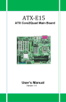
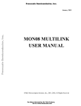
PCL-731
48-bit Digital I/O Card
Copyright
This documentation is copyrighted 1994 by Advantech Co., Ltd.
All rights are reserved. Advantech Co., Ltd. reserves the right to
make improvements in the products described in this manual at
any time without notice.
No part of this manual may be reproduced, copied, translated or
transmitted in any form or by any means without the prior written
permission of Advantech Co., Ltd. Information provided in this
manual is intended to be accurate and reliable. However, Advantech Co., Ltd. assumes no responsibility for its use, nor for any
infringements of the rights of third parties which may result from
its use.
Acknowledgments
PC-LabCard is a trademark of Advantech Co., Ltd. IBM and PC are
trademarks of International Business Machines Corporation.
OPTO-22 is a trademark of OPTO-22 Corporation.
Москва:
Телефон: (095) 234-0636 (4 линии)
Факс: (095) 234-0640
BBS: (095) 336-2500
Web: http://www.prosoft.ru
E-mail: [email protected]
Для писем: 117313, Москва, а/я 81
С.-Петербург: (812) 325-3790
Екатеринбург: (3432) 49-3459
Contents
Chapter 1
General information ...................................................... 1
Introduction ....................................................................... 2
Features .............................................................................. 2
Applications ....................................................................... 2
Specifications .................................................................... 3
Connector pin assignments ............................................... 4
Block diagram ................................................................... 5
Chapter 2
Installation ....................................................................... 7
Initial inspection ................................................................ 8
Switch and jumper settings ............................................... 8
Chapter 3
Operation ........................................................................ 13
Configuration ................................................................... 14
Interrupt handling ............................................................ 17
Chapter 4
Programming .................................................................. 19
Demo programs ............................................................... 21
CHAPTER
General
Chapter 1
1
information
General Information
1
Introduction
The PCL-731 is a 48-bit DIO card. It provides you with 48 bits of
parallel digital input/output and emulates mode 0 of the 8255
PPI chip. Buffered inputs and outputs offer a high driving
capacity.
The card’s 48 bits are divided into six 8-bit I/O ports:
A0, B0, C0, A1, B1 and C1. You can configure each port as either
input or output via software. The card also offers two hardware
interrupt lines to the PC.
The card offers two 50-pin OPTO-22 compatible connectors
which can connect to a PCLD-7216 SSR I/O module carrier board,
PCLD-885 power relay output board, PCLD-785B and PCLD7225 24/16-channel relay output boards or a PCLD-782B 24/16
channel opto-isolated D/I board.
Features
• 48 TTL digital I/O lines.
• Emulates mode 0 of 8255 PPI
• Interrupt handling
• OPTO-22 compatible 50-pin connectors
• Output status readback
Applications
• Industrial AC/DC I/O module monitoring and control
• Relay and switch monitoring and control
• Parallel data transfer
• Sensing the signals of TTL, DTL, CMOS logic
• Driving indicator LEDs
2
PCL-731 48 Bit Digital I/O Card
User's Manual
Specifications
I/O address assignments
Address
Function
BASE+0
PORT A0
BASE+1
PORT B0
BASE+2
PORT C0
BASE+3
CFG REG
BASE+4
PORT A1
BASE+5
PORT B1
BASE+6
PORT C1
BASE+7
CFG REG
Input signal
• Logic high voltage: 2.0 to 5.25 V
• Logic low voltage: 0.0 to 0.80 V
• High level input current: 20 µA
• Low level input current: -0.2 mA
Output signal
• Logic high voltage: 2.4 V Min.
• Logic low voltage: 0.4 V Max.
• High level output current: -15 mA Max. (source)
• Low level output current: 24 mA Max. (sink)
• Driving capacity: 15 LS TTL
Transfer rate
• Typical: 300 Kbytes/sec
• Maximum: 500 Kbytes/sec
Chapter 1
General Information
3
Power consumption
• Typical: 0.5 A @ 5 VDC (±5%)
Connector pin assignments
The PCL-731 features two OPTO-22 compatible 50-pin connectors. Pin assignments are as follows:
CN1
PC 07
PC 06
PC 05
PC 04
PC 03
PC 02
PC 01
PC 00
PB 07
PB 06
PB 05
PB 04
PB 03
PB 02
PB 01
PB 00
PA 07
PA 06
PA 05
PA 04
PA 03
PA 02
PA 01
PA 00
+5 V
1
3
5
7
9
11
13
15
17
19
21
23
25
27
29
31
33
35
37
39
41
43
45
47
49
2
4
6
8
10
12
14
16
18
20
22
24
26
28
30
32
34
36
38
40
42
44
46
48
50
CN2
GND
GND
GND
GND
GND
GND
GND
GND
GND
GND
GND
GND
GND
GND
GND
GND
GND
GND
GND
GND
GND
GND
GND
GND
GND
PC 17
PC 16
PC 15
PC 14
PC 13
PC 12
PC 11
PC 10
PB 17
PB 16
PB 15
PB 14
PB 13
PB 12
PB 11
PB 10
PA 17
PA 16
PA 15
PA 14
PA 13
PA 12
PA 11
PA 10
+5 V
1
3
5
7
9
11
13
15
17
19
21
23
25
27
29
31
33
35
37
39
41
43
45
47
49
PCL-731 Block Diagram
4
PCL-731 48 Bit Digital I/O Card
User's Manual
2
4
6
8
10
12
14
16
18
20
22
24
26
28
30
32
34
36
38
40
42
44
46
48
50
GND
GND
GND
GND
GND
GND
GND
GND
GND
GND
GND
GND
GND
GND
GND
GND
GND
GND
GND
GND
GND
GND
GND
GND
GND
Block diagram
Decoder
I/O CKT
Data Bus
Address Bus
Control Bus
8255
Port A0
Port B0
Port C0
Port A1
Port B1
Port C1
CN1
8
8
8
OPTO 22
Connector
8
CN2
8
OPTO 22
Connector
8
PC00
Interrupt
Handling
PC10
IRQ2
IRQ3
IRQ4
IRQ5
IRQ6
IRQ7
IRQ10
IRQ11
IRQ12
IRQ15
IRQ2
IRQ3
IRQ4
IRQ5
IRQ6
IRQ7
IRQ10
IRQ11
IRQ12
IRQ15
Chapter 1
General Information
5
6
PCL-731 48 Bit Digital I/O Card
User's Manual
CHAPTER
2
Installation
Chapter 2
Installation
7
Initial inspection
Before you install the PCL-731, first check to make sure it was not
damaged during shipping. If you find any damage or the card fails to
meet specifications, please contact your local dealer or sales representative. Also contact the shipper and save the shipping materials for the
shipper's inspection.
Switch and jumper settings
We designed the PCL-731 with ease-of-use in mind. It has one
function switch and six jumper settings. The following sections tell
how to configure the card. You may want to refer to the figure below
for help in identifying card components.
Warning: Do not install or remove the PCL-731
I/O card while the power is ON,
as this may damage the card.
The following diagram shows the location of switches and jumpers:
Figure 2-1: Jumper and switch locations
8
PCL-731 48 Bit Digital I/O Card
User's Manual
Base address selection (SW1)
You control the PCL-731's operation by reading or writing data to the
PC's I/O (input/output) port addresses. The card requires 8 consecutive
address locations. Switch SW1 sets the card's base (beginning)
address. Valid base addresses range from Hex 000 to Hex 3F8. Other
devices in your system may, however, be using some of these addresses.
We set the PCL-731 for a base address of Hex 300 at the factory. If
you need to adjust it to some other address range, set switch SW1 as
shown below:
Card I/O addresses (SW1)
Range (hex)
Switch position
1
2
3
4
5
6
7
000 - 007
l
l
l
l
l
l
l
008 - 00F
l
l
l
l
l
l
¡
200 - 207
¡
l
l
l
l
l
l
208 - 20F
¡
l
l
l
l
l
¡
¡
¡
l
l
l
l
l
¡
¡
¡
¡
¡
¡
¡
×
×
* 300 - 307
×
3F8 - 3FF
¡ = Off l = On
* = default
Switches 1-7 control the PC bus address lines as follows:
Switch
1
2
3
4
5
6
7
Line
A9
A8
A7
A6
A5
A4
A3
Chapter 2
Installation
9
Interrupt settings (JP5, JP6)
Jumpers JP5 and JP6 control the IRQ levels, as shown below:
2
3
4
5
6
2
7 10 11 12 15
3
4
5
6
7 10 11 12 15
o o o o o o o o o o
o o o o o o o o o o
o o o o o o o o o o
o o o o o o o o o o
JP5 (PC00)
JP6 (PC10)
(Default)
(Default)
Note: You must set each I/O line to a different interrupt level.
Interrupt level (JP1, JP2)
Jumpers JP1 and JP2 select the trigger edge (rising or falling) for I/O
lines PC00 and PC10, respectively. Jumpers settings appear below:
JP1 and JP2
Rising edge interrupt triggering
Falling edge interrupt triggering
(Default)
If you set the PCL-731 to trap on a rising edge, the card will generate
an interrupt if the I/O line (PC00 or PC10) changes from TTL LOW to
TTL HIGH. Conversely, if you set the card to trap on a falling edge
change, then it will generate an interrupt when the I/O line changes
from TTL HIGH to TTL LOW.
10
PCL-731 48 Bit Digital I/O Card
User's Manual
Interrupt mode (JP3, JP4)
The PCL-731 provides two I/O lines (PC00 and PC10) which you can
use to generate hardware interrupts to the PC. Jumper JP3 controls
interrupt line PC00, and jumper JP4 controls interrupt line PC10. The
DIS setting for each jumper (shown in the figure below) disables the
corresponding line's interrupt capability. The EN setting enables the
line's interrupt capability.
JP3 and JP4
DIS
S/W
EN
(Default)
The S/W setting allows you to enable and disable control by external
or programmable interrupt. I/O line PC04 controls the interrupt on
line PC00, and line PC14 controls the interrupt on line PC10. Bring
line PC04 to TTL LOW to enable the interrupt capability on PC00.
Send line PC04 to TTL HIGH to disable the interrupt capability on
PC00. I/O line PC14 controls PC10 in the same way.
Chapter 2
Installation
11
12
PCL-731 48 Bit Digital I/O Card
User's Manual
CHAPTER
3
Operation
Chapter 3
Operation
13
The PCL-731 emulates MODE 0 of an Intel 8255 programmable
peripheral interface (PPI) chip. The card is pin compatible with
most industrial solid state I/O racks and modules, such as those
manufactured by OPTO-22, Potter Brumfield, Gordos, etc.
The PCL-731's two 50-pin male IDC connectors interface with
directly to OPTO-22 racks. The PCL-731 offers two I/O lines
(PC00 and PC10) to generate hardware interrupts, as described on
page 10.
Configuration
Mode 0 of the 8255 provides simple input/output functions. No
handshaking is required since you read or write data directly to or
from a specified port.
8255 MODE 0 function definitions
• Six 8-bit ports (Port A0, B0, C0, A1, B1 and C1)
• Any port can be used for input or output
• Outputs are latched, whereas inputs are not latched
The PCL-731 requires ten I/O ports, identified below:
I/O port assignments
14
Location
BASE+0
Write
8255 Port A0
Read
8255 Port A0
BASE+1
8255 Port B0
8255 Port B0
BASE+2
8255 Port C0
8255 Port C0
BASE+3
8255 Mode Register
for Ports A0, B0 and C0
N/A
BASE+4
8255 Port A1
8255 Port A1
BASE+5
8255 Port B1
8255 Port B1
BASE+6
8255 Port C1
8255 Port C1
BASE+7
8255 mode Register
for Ports A1, B1 and C1
N/A
PCL-731 48 Bit Digital I/O Card
User's Manual
8255 data registers
The PCL-731’s I/O ports (BASE+0 to 2 and BASE+4 to 6) directly
map to the 8255 ports. Bit assignments for each I/O port appear
below:
BASE+0 8255 Port A0 (read/write)
Bit
7
Value PA07
6
5
4
3
2
1
0
PA06
PA05
PA04
PA03
PA02
PA01
PA00
BASE+1 8255 Port B0 (read/write)
Bit
7
Value PB07
6
5
4
3
2
1
0
PB06
PB05
PB04
PB03
PB02
PB01
PB00
BASE+2 8255 Port C0 (read/write)
Bit
7
Value PC07
6
5
4
3
2
1
0
PC06
PC05
PC04
PC03
PC02
PC01
PC00
BASE+4 8255 Port A1 (read/write)
Bit
7
Value PA17
6
5
4
3
2
1
0
PA16
PA15
PA14
PA13
PA12
PA11
PA10
BASE+5 8255 Port B1 (read/write)
Bit
7
Value PB17
6
5
4
3
2
1
0
PB16
PB15
PB14
PB13
PB12
PB11
PB10
BASE+6 8255 Port C1 (read/write)
Bit
7
Value PC17
6
5
4
3
2
1
0
PC16
PC15
PC14
PC13
PC12
PC11
PC10
Chapter 3
Operation
15
8255 mode registers
BASE+3 8255 Mode Register, A0, B0, C0 (write)
Bit
7
6
5
4
3
2
1
0
Value 1
0
0
PA0
PC0H
0
PB0
PC0L
Where:
PA0:
0 = Port A0 as output
1 = Port A0 as input
PB0:
0 = Port B0 as output
1 = Port B0 as input
PC0L: 0 = Port C0 low-nibble as output
1 = Port C0 low-nibble as input
(PC03-PC00)
PC0H: 0 = Port C0 high-nibble as output
1 = Port C0 high-nibble as input
(PC07-PC04)
BASE+7
8255 Mode Register, A1, B1, C1
(write)
Bit
7
6
5
4
3
2
1
0
Value 1
0
0
PA1
PC1H
0
PB1
PC1L
Where:
PA1: 0 = Port A1 as output
1 = Port A1 as input
PB1: 0 = Port B1 as output
1 = Port B1 as input
PC1L: 0 = Port C1 low-nibble as output
1 = Port C1 low-nibble as input
(PC13-PC10)
PC1H:0 = Port C1 high-nibble as output
1 = Port C1 high-nibble as input
(PC17-PC14)
Note:
16
After power-on or reset, all ports (Port A0, B0, C0,
A1, B1 and C1) are set to input mode.
PCL-731 48 Bit Digital I/O Card
User's Manual
Interrupt handling
The PCL-731 offers two I/O lines, PC00 and PC10, which you can
use to generate a hardware interrupt to the CPU. Interrupts are
edge-triggered. Please refer to page 10 for jumper settings and
description.
Note:
Since the PCL-731’s digital input data are not
latched, the card provides no “first event” trapping
to determine which input was active first.
Although interrupts are normally triggered by external signals, the
PCL-731 can send output data to emulate an interrupt singal. See
the example programs in the following section.
Chapter 3
Operation
17
18
PCL-731 48 Bit Digital I/O Card
User's Manual
CHAPTER
4
Programming
Chapter 4
Programming
19
The following programming examples show how to use the card's
readback function to monitor the output status, how to use the
interrupt function (rising and falling edge) and how to set the
initial value for the output port. The example programs run under
Turbo C version 2.0 or later.
Programming notes
You can program the PCL-731's ports in software for input, output
or tri-state. When you power-on or reboot your system, however,
all of the ports will be reset to input. When you configure one of
the ports for output for the first time and sent data to it, it will not
output until you have set the output buffer. This prevents external
devices from being damaged before they are initialized. When a
port is set for output, a read action on the port will return the data
to be output.
20
PCL-731 48 Bit Digital I/O Card
User's Manual
Demo programs
/
********************************************************
* This demo program shows how to use the PCL-731’s*
* readback function to monitor the output status. *
*
*
* Hardware setting:
*
*
1. Base address set at 0x300
*
*********************************************************/
#include <stdio.h>
#include <conio.h>
#include <process.h>
#include <dos.h>
main()
{
int base = 0x300; /* set base address to
int portA;
/* save readback value
int portB;
/* save readback value
int portC;
/* save readback value
int i,j;
300 (hex) */
of port_A1*/
of port_B1*/
of port_C1*/
/* handle screen */
clrscr();
gotoxy(30,3);
textattr(0x70);
cputs(“PCL-731 DEMO PROGRAM”);
gotoxy(11,6);
printf(“PortA0 output value —> “);
gotoxy(11,8);
printf(“PortB0 output value —> “);
gotoxy(11,10);
printf(“PortC0 output value —> “);
gotoxy(43,6);
printf(“PortA1 Readback —> “);
gotoxy(43,8);
printf(“portB1 Readback —> “);
gotoxy(43,10);
printf(“portC1 Readback —> “);
Chapter 4
Programming
21
/* initialization */
outportb (base+3,0x80); /* set 8255 port0 all as
output */
/*********************** main program ***/
for ( j=0;j<0x100;j++ )
{
outportb (base,j); /* out j to port A0 */
gotoxy (34,6);
printf(“%2x”,j);
portA = inportb (base);
gotoxy(63,6);
printf(“%2x”,portA);
if ( portA != j )
{
printf (“\7”); /* beep */
gotoxy (30,13);
textattr(0x09);
cprintf(“PortA1 readback error!”);
getch();
exit(1); /* quit to dos */
}
outportb (base+1,j); /* out j to port B0 */
gotoxy (34,8);
printf(“%2x”,j);
portB = inportb (base+1);
gotoxy(63,8);
printf(“%2x”,portB);
if ( portB != j )
{
printf (“\7”); /* beep */
gotoxy (30,13);
textattr(0x09);
cprintf(“PortB1 readback error!”);
getch();
exit(1); /* quit to dos */
}
22
PCL-731 48 Bit Digital I/O Card
User's Manual
outportb (base+2,j); /* out j to port C0 */
gotoxy (34,10);
printf(“%2x”,j);
portC = inportb (base+2);
gotoxy(63,10);
printf(“%2x”,portC);
if ( portC != j )
{
printf (“\7”); /* beep */
gotoxy (30,13);
textattr(0x09);
cprintf(“PortC1 readback error!”);
getch();
exit(1); /* quit to dos */
}
} /* end of for */
} /* end of main() */
Chapter 4
Programming
23
/
*******************************************************
* This demo program shows how to use the interrupt *
* function (rising edge) of the PCL-731.
*
* Hardware settings:
*
*
1. Base address set at 0X300
*
*
2. JP5 set at IRQ 2
*
*
3. JP3 set at EN or S/W
*
*
4. JP1 set at RISING trigger
*
*********************************************************/
#include <dos.h>
#include <stdio.h>
#include <conio.h>
/* new INT 0AH ISR */
void interrupt alarm (void)
{
char Port61_Old_Status;
char Port61_New_Status;
int DelayTime = 0x300;
int Count = 0;
int i;
/** get original port 61H status and save it **/
Port61_New_Status=Port61_Old_Status=inportb(0x61);
/** set port 61h bit1 to 0 **/
Port61_New_Status &= 0xfd; /* 1111 1101 in binary*/
for (Count=0;Count<0x300;Count++,DelayTime--)
{
Port61_New_Status ^= 0x02; /* ON/OFF bit1 */
outportb (0x61, Port61_New_Status);
for (i=0 ; i<DelayTime ; i++);
}
outportb (0x61, Port61_Old_Status);
outportb (0x20, 0x20); /* send EOI to 8259 */
} /* end of ISR */
24
PCL-731 48 Bit Digital I/O Card
User's Manual
void main()
{
int IMR,base=0x300;
void interrupt (*Int_A_Old_Vector)();
Int_A_Old_Vector = getvect(0x0a);/*get old int 0ah ISR*/
setvect (0x0a,alarm); /* set new int 0ah ISR */
IMR = inportb(0x21); /*get 8259 interrupt mask register*/
/* initialization */
outportb (base+3,0x80); /* set Port A0, B0, C0 to */
/* output mode */
clrscr();
printf(“Press any key to generate a rising edge"
"interrupt”);
getch();
outportb(0x21,0xfb & IMR); /* set IRQ2 nonmasked */
/* PC04=0—>interrupt enable, set PC00=0 and then set
PC00 = 1 to generate a rising edge signal */
outportb (base+2,0x0);
printf(“\n\nPort C0 = %x”,inportb(0x2c2));
/* generate a rising edge signal PC00 */
outportb (base+2,0x01); /* set PC04 = 0 -> interrupt
enable, set PC00 = 1 */
printf(“\n\nPort C0 = %x”,inportb(0x2c2));
printf(“\n\nPress any key to quit...”);
getch();
/* restore old INT 0AH ISR */
setvect (0x0a,Int_A_Old_Vector);
outportb (0x21,IMR); /* restore 8259 interrupt mask
*/
/* set ports as INPUT to release IRQ2 line */
outportb (base+3,0x9b);
} /* end of main() */
Chapter 4
Programming
25
/
********************************************************
* This demo program shows how to use the interrupt *
* function (falling edge) of the PCL-731.
*
* Hardware settings:
*
*
1. Base address set at 0X300
*
*
2. JP5 set at IRQ 2
*
*
3. JP3 set at EN or S/W
*
*
4. JP1 set at FALLING trigger
*
*********************************************************/
#include <dos.h>
#include <stdio.h>
#include <conio.h>
/* new INT 0AH ISR */
void interrupt alarm (void)
{
char Port61_Old_Status;
char Port61_New_Status;
int DelayTime = 0x300;
int Count = 0;
int i;
/** get original port 61H status and save it **/
Port61_New_Status=Port61_Old_Status=inportb(0x61);
/** set port 61h bit1 to 0 **/
Port61_New_Status &= 0xfd; /* 1111 1101 in binary */
for ( Count=0; Count < 0x300; Count++, DelayTime--)
{
Port61_New_Status ^= 0x02; /* ON/OFF bit1 */
outportb (0x61,Port61_New_Status);
for (i=0;i<DelayTime;i++);
}
outportb (0x61,Port61_Old_Status);
outportb (0x20,0x20); /* send EOI to 8259 */
} /* end of ISR */
26
PCL-731 48 Bit Digital I/O Card
User's Manual
void main()
{
int IMR,base=0x300;
void interrupt (*Int_A_Old_Vector)();
/* get old int0Ah ISR*/
Int_A_Old_Vector = getvect(0x0a);
setvect (0x0a,alarm); /* set new int 0ah ISR */
/*get 8259 interrupt mask register*/
IMR = inportb(0x21);
/* initialization */
outportb (base+3,0x80); /* set Port A0, B0 and C0 */
/* to output mode */
clrscr();
printf(“Press any key to generate a falling edge"
"interrupt”);
getch();
outportb(0x21,0xfb & IMR); /* set IRQ2 nonmasked */
/* PC04=0 —> interrupt enable, set PC00=1, then set
PC00=0 to generate a falling edge signal */
outportb (base+2,0x01);
printf(“\n\nPort C0 = %x”,inportb(0x2c2));
/* generate a falling edge signal PC00 */
/* PC04=0 -> interrupt enable, set PC00=0 */
outportb (base+2 , 0x00);
printf(“\n\nPort C0 = %x”,inportb(0x2c2));
printf(“\n\nPress any key to quit...”);
getch();
/* restore old INT 0AH ISR */
setvect (0x0a,Int_A_Old_Vector);
/* restore 8259 interrupt mask */
outportb(0x21,IMR);
/* set as INPUT to release IRQ2 line */
outportb(base+3,0x9b);
} /* end of main() */
Chapter 4
Programming
27
/
********************************************************
*
This demo program demonstrates how to set the *
*
PCL-731's output port to an initial value.
*
*
*
*
Hardware setting:
*
*
1. Base address set at 0x300
*
**********************************************************/
#include
#include
#include
#include
<stdio.h>
<conio.h>
<process.h>
<dos.h>
main()
{
int base = 0x300; /* set base address to 300(hex)*/
/* handle screen */
clrscr();
gotoxy(30,3);
textattr(0x70);
cputs(“PCL-731 DEMO PROGRAM”);
gotoxy(27,6);
printf(“portA0 output value —> ffH”);
gotoxy(27,8);
printf(“portB0 output value —> 0H”);
gotoxy(27,10);
printf(“portC0 output value —> ffH”);
/********************* main program **************/
/* Initialization */
outportb (base+3,0x80); /* set 8255 port 0 all as
output */
outportb (base,0xff);
/* out ffH to port A0 */
outportb (base+1,0x0); /* out 0H to port B0 */
outportb (base+2,0xff); /* out ffH to port C0 */
} /* end of main() */
28
PCL-731 48 Bit Digital I/O Card
User's Manual