1
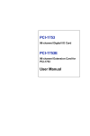
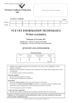
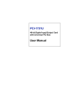
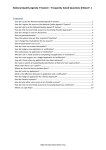
MIC-3753 User’s Manual Copyright The documentation and the software included with this product are copyrighted 2003 by Advantech Co., Ltd. All rights are reserved. Advantech Co., Ltd. reserves the right to make improvements in the products described in this manual at any time without notice. No part of this manual may be reproduced, copied, translated or transmitted in any form or by any means without the prior written permission of Advantech Co., Ltd. Information provided in this manual is intended to be accurate and reliable. However, Advantech Co., Ltd. assumes no responsibility for its use, nor for any infringements of the rights of third parties, which may result from its use. CE notification The MIC-3753, developed by ADVANTECH CO., LTD., has passed the CE test for environmental specifications when shielded cables are used for external wiring. We recommend the use of shielded cables. This kind of cable is available from Advantech. Please contact your local supplier for ordering information. On-line Technical Support For technical support and service, please visit our support website at: http://www.advantech.com/support Part No. 2003375300 Printed in Taiwan 1st Edition January 2004 Contents Chapter 1 INTRODUCTION.......................................................................1 1.1 INTRODUCTION ................................................................................2 1.2 FEATURES .........................................................................................4 1.3 APPLICATIONS ..................................................................................4 1.4 SPECIFICATIONS ................................................................................5 1.5 PIN ASSIGNMENT ..............................................................................6 1.6 BLOCK DIAGRAM ............................................................................7 Chapter 2 HARDWARE INSTALLATION ................................................9 2.1 UNPACKING ...................................................................................10 2.2 HARDWARE INSTALLATION ............................................................12 2.3 BOARD LAYOUT: DIMENSIONS .......................................................15 Chapter 3 OPERATION.............................................................................21 3.1 OVERVIEW ........................................................................................22 3.2 DIGITAL I/O PORTS ..........................................................................22 3.3 INTERRUPT FUNCTIONS.....................................................................25 APPENDIX A REGISTER FORMAT.......................................................31 A.1 REGISTER FORMAT ........................................................................32 CHAPTER 1 Introduction 1 1.1 Introduction The MIC-3753 is a 72-bit digital I/O card for the CompactPCI® bus. The card emulates mode 0 of the 8255 PPI chip, but the buffered circuits offer a higher driving capability than the 8255. The 72 I/O lines are divided into nine 8-bit I/O ports: A0, B0, C0, A1, B1, C1, A2, B2, C2. You can configure each port as input or output via software. Easy to Install: Plug and Play The MIC-3753 uses a PCI controller to interface the card to the CompactPCI bus. The controller fully implements the PCI bus specification Rev 2.1. All bus relative configurations, such as base address and interrupt assignment, are automatically controlled by software. Dry Contact Support for Digital Input Each digital input channel at the MIC-3753 accepts either 0 ~5 VDC wet contact or dry contact inputs. This dry contact capability allows the channel to respond to changes in external circuitry (e.g., the closing of a switch in the external circuitry) when no voltage is present in the external circuit. Reset Protection Fulfills the True Requirement of Industrial Applications When the system is hot reset (the power is not turned off), the MIC-3753 can either retain the last I/O port settings and outputs value, or return to its default configuration, depending on the jumper setting. This function protects the system from wrong operations during unexpected system resets. 2 MIC-3753 User Manual Interrupt Functions Ensure Faster System Response Two lines of each port C (i.e., ports C0, C1 and C2) are connected to an interrupt circuit. The “Interrupt Control Register” of the MIC-3753 controls how these signals generate an interrupt. More than one interrupt request signals can be generated at the same time, and then the software can process these request signals by ISR. The multiple interrupt sources provide the card with more capability and flexibility. The MIC-3753 also provides a “Pattern Match” interrupt function for port A0. The card monitors the states of port A0 and compares them with a pre-set pattern. When the received state matches the pre-set pattern, the MIC-3753 generates an interrupt signal to the system. The “Change of State” interrupt function is provided at port B0. When any signal line of port B0 changes its state, the card generates an interrupt to the system to handle this event. These interrupt functions release the CPU from the burden of polling all I/O points, enabling a PC to handle more I/O points with higher performance. Chapter 1 Introduction 3 1.2 Features ! 72 TTL digital I/O lines ! Emulates mode 0 of 8255 PPI ! Buffered circuits for higher driving capacity than 8255 ! Multiple-source interrupt handling ! Interrupt output pin for simultaneously triggering external devices with the interrupt ! Output status read-back ! “Pattern match” and “Change of state” interrupt functions for critical I/O monitoring ! Keeps I/O setting and digital output values when hot system reset ! Supports dry contact and wet contact ! High-density 78-pin D_SUB connector 1.3 Applications ! Industrial AC/DC I/O devices monitoring and controlling ! Relay and switch monitoring and controlling ! Parallel data transfer ! TTL, DTL and CMOS logic signal sensing ! Indicator LED driving 4 MIC-3753 User Manual 1.4 Specifications ! I/O Channels: 72 digital I/O lines ! Programming Mode 8255 PPI mode 0 ! Input Signal: Logic level 0: 0.8 V max. Logic level 1: 2.0V min. ! Output Signal: Logic level 0: 0.44V max. @ 24 mA (sink) Logic level 1: 3.76V min. @ 24mA (source) ! Power Consumption: +5 V @ 350mA (typical) +5 V @ 2A (max.) ! Operating Temperature 0 ~ +60°C (32 ~ 140°F) (refer to IEC 68-2-1, 2) ! Storage Temperature -20 ~ +70°C (-4 ~ 158°F) ! Operating Humidity 5 ~ 95%RH non-condensing (refer to IEC 68-2-3) ! Connector: 78 DB connector ! Dimensions: 160 x 100 mm Chapter 1 Introduction 5 1.5 Pin Assignment PA00 ~ PA07 : I/O p ins of Port A0 PA10 ~ PA17 : I/O p ins of Port A1 PA20 ~ PA27 : I/O p ins of Port A2 PB00 ~ PB07 : I/O p ins of Port B0 PB10 ~ PB17 : I/O p ins of Port B1 PB20 ~ PB27 : I/O p ins of Port B2 PC00 ~ PC07 : I/O pins of Port C0 PC10 ~ PC17 : I/O pins of Port C1 PC20 ~ PC27 : I/O pins of Port C2 GND : G round Figure 1-1: MIC-3753 DB 78 Female Connector Pin Assignment 6 MIC-3753 User Manual 1.6 Block Diagram Figure 2-1: MIC-3753 Block Diagram Chapter 1 Introduction 7 8 MIC-3753 User Manual CHAPTER 2 Hardware Installation 9 This chapter gives users a package item checklist, proper instructions about unpacking and step-by-step procedures for card hardware installation. 2.1 Unpacking After receiving your MIC-3753 package, please inspect its contents first. The package should contain the following items: # MIC-3753 card # Companion CD-ROM (DLL driver included) # User’s Manual The MIC-3753 card has electronic components vulnerable to electrostatic discharge (ESD). ESD could easily damage the integrated circuits and certain components if preventive measures are not carefully paid attention to. Before removing the card from the antistatic plastic bag, you should take following precautions to ward off possible ESD damage: ! Touch the metal part of your computer chassis with your hand to discharge static electricity accumulated on your body. Or use a grounding strap. ! Touch the anti-static bag to a metal part of your computer chassis before opening the bag. ! Take hold of the card only by the metal bracket when removing it from the bag. 10 MIC-3753 User Manual After taking out the card, first you should: ! Inspect the card for any possible signs of external damage (loose or damaged components, etc.). If the card is visibly damaged, please notify our service department or the local sales representative immediately. Avoid installing a damaged card into your system. Also, pay extra caution to the following aspects to ensure proper installation: ! Avoid physical contact with materials that could hold static electricity such as plastic, vinyl and Styrofoam. ! Whenever you handle the card, grasp it only by its edges. DO NOT TOUCH the exposed metal pins of the connector or the electronic components. Note: Keep the anti-static bag for future use. You might need the original bag to store the card if you have to remove the card from the PC or transport it elsewhere. Chapter 2 Hardware Installation 11 2.2 Hardware Installation Note: Make sure you have installed the driver before you install the card. We strongly recommend that you install the software driver before you install the hardware into your system, since this will guarantee a smooth and trouble-free installation process. For more information about the driver installation, configuration and removal procedures for Windows 9X, Windows NT, Windows 2K and Windows XP, please see the corresponding help file: (link to the help file ) When you install the MIC-3756 Card, Please make sure the installation of the DLL for MIC-3756 is completed. You can then go on to install the MIC-3756 card in your CompactPCI system. It is suggested that you refer to the user manual or related documentation if you have any doubt. Please follow the steps below to install the card on your system. To install a card: Step 1: Remove the cover of an unused slot of your CompactPCI computer slot. Step 2: Hold the card vertically. Be sure that the card is pointing in the correct direction. The components of the card should be pointing to the right-hand side and the black handle of the card should be pointing to lower edge of the backplane. Step 3: Holding the lower handle, pull the handle down to unlock it. Step 4: Insert the MIC-3753 card into the CompactPCI chassis carefully by sliding the lower edges of the card into the card guides. 12 MIC-3753 User Manual Step 5: Push the card into the slot gently by sliding the card along the card guide until J1 meets the long needle on the backplane, and the Blue LED on the front panel of the card lights up. Note: If your card is correctly positioned and has been slid all the way into the chassis, the handle should match the rectangular holes. If not, remove the card from the card guide and repeat step 3 again. Do not try to install a card by forcing it into the chassis. Step 6: Now push the card into place rightly, and the Blue LED is going to be turned off. Step 7: Secure the card by pushing in the handle to lock it into place, after the Blue LED has been turned off. Step 8: If your CompactPCI computer power is on, the system can now configure the card automatically. After the system has finished the device configuration, you can find the card information in the Device Manager. Note: If your card is properly installed, you should see the device name of your card listed on the Device Manager tab. To remove a card: Step 1: Push the handle down to unlock the card, and the CompactPCI system will uninstall the card configuration automatically. Step 2: After the system has finished the device configuration, the Blue LED on the card is lit. Now you can slide the card out. Chapter 2 Hardware Installation 13 Note: Because of the card’s hot swap capability, the steps above are for removing a card when the system is on. If system power is off, please do step1 and step2 without attending the Blue LED’s state. 14 MIC-3753 User Manual 2.3 Board Layout: Dimensions Fig. 2-1: MIC-3753 Board Layout Chapter 2 Hardware Installation 15 Connector MIC-3753 has one 78-pin DB female connector. For more details about switch and connector, please see Chapter 4 Pin Assignment & Signal. 2.4 Jumper & Switches Settings The MIC-3753 has been designed with ease-of-use in mind. It is a "plug and play" card, i.e. the system BIOS assigns the system resources such as base address and interrupt automatically. There are only two functions with one jumper and three switches on the MIC-3753. The following section describes how to configure the card. You may want to refer to the figure below for help in identifying card components. Figure 2-2: Location of connectors and jumpers 16 MIC-3753 User Manual Switch (SW2, SW3, SW4)Settings to Set Ports as Input or Output by Software When the switch of JPA0, JPB0, JPC0L, JPC0H, JPA1, JPB1, JPC1L, JPC1H, JPA2, JPB2, JPC2L or JPC2H are all “OFF” (i.e., by setting the switch), the corresponding ports are set to be configurable as input or output ports by software (PA0 means switch pin for port A0, PB0 means switch pin for port B0, etc. See Figure 2-3 & Table 2-1). Figure 2-3 Switches (SW2,SW3,SW4) to Set Ports as Output Ports By Setting the switches of PA0, PB0, PC0L, PC0H, PA1, PB1, PC1L, PC1H, PA2, PB2, PC2L or PC2H “ON”, a user sets the corresponding ports to be output ports. (PA0 means switch pin for port A0, PB0 means switch pin for port B0, etc.) The initial state of each of these ports after system power on or reset will be logic 0 (voltage low), unless jumper JP1 determines otherwise. (See Jumper JP1 below.) Figure 2-4 Chapter 2 Hardware Installation 17 Set port as Set port I/O by Output software PC0L ON OFF PB0 ON OFF PC0H ON OFF PA0 ON OFF PC1L ON OFF PB1 ON OFF PC1H ON OFF PA1 ON OFF PC2L ON OFF PB2 ON OFF PC2H ON OFF PA2 ON OFF Switch SW2 SW3 SW4 Table 2-1: Switches Setting Jumper JP1 Restores Ports to Their Condition Prior to Reset Jumper JP1 gives the MIC-3753 a new and valuable capability. With JP1 enabled (i.e., by shorting the lower two pins of JP1), the MIC-1753 "memorizes" all port I/O settings and output values, and, in the event of a "hot" reset, the settings and output values present at the port just prior to reset are restored to each port following reset. This feature applies to both ports set by software, and to ports configured as output ports via a jumper. Depending on the application, this capability may allow a card to be reset without requiring a complete shutdown of processes controlled by the card (since port values are left unchanged and are interrupted only momentarily). 18 MIC-3753 User Manual Complete loss of power to the chip clears chip memory. Thus, even if JP1 is enabled, if the power to the card is disconnected, the card's initial power-on state will be the state of an input port with voltage high input (for software-set ports) or the state of an output port with voltage low output (for jumper-set ports). When jumper JP1 is not enabled (i.e., by shorting the upper two pins of JP1), both power-off and reset results in ports returning to the state of an input port with voltage high input (for software-set ports) or returning to the state of output port with voltage low output (for jumper-set ports). Jumper Function description Enables the reset protection function. All ports return to the state held just prior to reset JP1 Disables the reset protection function. All ports return to the default state (for software-set) or to output port, output low (for jumper-set ports) (default) Table 2-2: JP1 Setting Chapter 2 Hardware Installation 19 20 MIC-3753 User Manual CHAPTER Operation 3 21 3.1 Overview This chapter describes the operating characteristics of the MIC-3753. The driver software bundled with this card allows a user to access all of the card's functions without register level programming. Please see the User's Manual included on the driver CD-ROM for more information. For users who prefer to implement their own bit-level programming to drive the card's functions, information useful for making such a program is included in this chapter. 3.2 Digital I/O Ports Introduction The MIC-3753 each emulates three 8255 programmable peripheral interface (PPI) chips in mode 0, but with higher driving capability than a standard 8255 chip. Each of these 8255 chip emulators has 24 programmable I/O pins that are divided into three 8-bit ports. The total 72 digital I/O pins on either the MIC-3753 are divided into 9 ports, designated PA0, PB0, PC0, PA1,PB1, PC1, PA2, PB2 and PC2. Each port can be programmed as an input or an output port. The I/O pins in port A0 are designated PA00, PA01, ..., PA07; the pins in port B0 are designated PB00, PB01, ..., PB07, etc. These port names are used both in this manual and in the software library. Please refer to Section 1.5, Pin Assignments. 8255 Mode 0 The basic 8255 mode 0 features included on the MIC-3753 cards are: • 8-bit I/O ports - port A (PA) and port B (PB) • Port C is divided into two nibble-wide (4-bit) I/O ports - PC upper and PC lower • Any port can be used for either input or output. • Output status can be read back. 22 MIC-3753 User Manual Input/Output Control A control word can be written to a port's configuration register (Base+3, 7 and 11 respectively for ports 0, 1 and 2 on the MIC-3753) to set the port as an input or an output port, unless the ports are set as output ports via a switch (refer to Section 2.4, Jumper & Switches Settings). Table 3-1 shows the format of a control word. D7 Not read D6 Not read D5 Not read D4 Port A 0:output 1:input D3 D2 D1 Port C Not Port B upper bits read 0:output 0:output 1:input 1:input Table 3-1: Bit map of port configuration register D0 Port C low bits 0:output 1:input Note! : A control word has no effect if a jumper sets the corresponding port as an output port. Warning! Before setting any port as an output port via software, make sure that a safe output value has also been set. An output voltage will appear at the pins immediately following the control word taking effect. If no output value was specified, the value will be Indeterminate (either 0 or 1), which may cause a dangerous condition. Initial Configuration The initial configuration of each port depends on the input/output switches setting of each port, on the setting of the jumper JP1, and on whether the power was actually disconnected or whether the system was hot reset. If jumper JP1 is not enabled, all ports configured by software are automatically set as input ports during system start up or reset, with a default signal level of logic 1 (high). All ports set via switches as output ports are set as output ports during system start up or reset, signal level logic 0 (0 V). If the jumper JP1 is enabled and the initial configuration is caused by a reset, all ports will return to the states they had just prior to the reset. The reset must be a "hot" reset (power not disconnected) for enabled JP1 to return ports to their prior values. Otherwise, the card behaves as though JP1 were not enabled. Please refer to "Jumper & Switches settings" in Chapter 2 for more information. Chapter 3 Operations 23 Dry Contact Support for Digital Input Each digital input channel accepts either dry contact or 0 ~ 5 VDC wet contact inputs. Dry contact capability allows the channel to respond to changes in external circuitry (e.g., the closing of a switch in the external circuitry) when no voltage is present in the external circuit. Figure 3-1 shows external circuitry with both wet and dry contact components, connected as an input source to one of the card's digital input channels. Figure 3-1: Wet and dry contact inputs Note! : For wet contact configurations, a malfunction may occur if the internal resistance of the voltage source is significant (>1.5kW ). It is advisable to connect a 1.5 kW resistor in parallel with such a voltage source to avoid a voltage rise inside the voltage source. 24 MIC-3753 User Manual 3.3 Interrupt Functions Introduction Two lines of each I/O port C, plus ports A0 and B0, are connected to the interrupt circuitry. The “Interrupt Control Register” of the MIC-3753 controls how the combination of these signals generates an interrupt. Six interrupt request signals can be generated at the same time, and then the software can service these six request signals by IRQ. The multiple interrupt sources provide the card with more capability and flexibility. IRQ Level The IRQ level is set automatically by the PCI plug-and-play BIOS and is saved in the PCI controller. There is no need for users to set the IRQ level. Only one IRQ level is used by this card, although it has six interrupt sources. Interrupt Control Registers The “Interrupt Control Registers” (Base + 16, 17 and18 for the MIC-3753) control the interrupt signal sources, edges and flags. The following table shows the bit map of each interrupt control register. These registers are readable / writable. When writing to one of them, it is used as a control register, and when reading from it, it is used as a status register. Base + 16 Bit# Abbreviation Base + 17 Bit# Abbreviation Base + 18 Bit# Abbreviation D7 F0 D6 E0 D5 M01 D7 F1 D6 E1 D5 M11 D7 F2 D6 E2 D5 M21 Port0 D4 D3 M00 F02 Port1 D4 D3 M10 Port2 D4 D3 M20 - D2 M2 D1 F01 D0 M1 D2 - D1 - D0 - D2 - D1 - D0 - Table 3-2: Interrupt control register bit map Chapter 3 Operations 25 Mn0 and Mn1: “mode bits” of port Cn (n = 0 ~ 2) M1: pattern match port enable control bit of port A0 M2: change of state port enable control bit of port B0 En: triggering edge control bit (n = 0 ~ 2) Fn: interrupt flag bit of port Cn (n = 0 ~ 2) F01: pattern patch interrupt flag bit of port A0 F02: change of state interrupt flag bit of port B0 Figure 3-2: Interrupt sources 26 MIC-3753 User Manual Interrupt Source Control The “mode bits” in the interrupt control registers determine the allowable sources of signals generating an interrupt. For the MIC-3753, bit 4 and bit 5 of Base+16 determine the interrupt source of port C0, bit 4 and bit 5 of Base+17 determine the interrupt source for port C1, and so forth. Please refer the table in Appendix A to find the corresponding address for the interrupt source control of each port C. The following table shows the relationship between an interrupt source and the values in the mode bits. Base + 16 Port0 Description M01 M00 Disable interrupt 0 0 Source = PC00 0 1 Source = PC00 and PC04 1 0 Disable interrupt 1 1 Base + 17 Port1 Description M11 M10 Disable interrupt 0 0 Source = PC00 0 1 Source = PC00 and PC04 1 0 Disable interrupt 1 1 Base +18 Port2 Description M11 M10 Disable interrupt 0 0 Source = PC00 0 1 Source = PC00 and PC04 1 0 Disable interrupt 1 1 Table 3-3: Interrupt mode bit values Interrupt Triggering Edge Control The interrupt can be triggered by a rising edge or a falling edge of the interrupt signal, selectable by the value written in the “triggering edge control” bit in the interrupt control register, as shown in following table. En (n = 0~2) 1 0 Triggering edge of interrupt signal Rising edge trigger Falling edge trigger Table 3-4: Triggering edge control bit values Chapter 3 Operations 27 Interrupt Flag Bit The “interrupt flag” bit is a flag indicating the status of an interrupt. It is a readable and writable bit. Read the bit’s value to find the status of the interrupt; write “1” to this bit to clear the interrupt. This bit must be cleared in the ISR to service the next incoming interrupt. F01,F02 and Fn Interrupt Status Read 1 Interrupt exists 0 No interrupt Write 1 Clear interrupt 0 Ignore Table3-5: Interrupt flag bit values F01: pattern patch interrupt flag bit of port A0 F02: change of state interrupt flag bit of port B0 Fn: interrupt flag bit of port Cn (n = 0 ~ 2) Pattern Match Interrupt Function The MIC-3753 provides a pattern match interrupt function for port A0. It monitors the status of the enabled input channels, which are chosen in Base+24, and compares the received state values with the pre-set state values written in Base+20. When the actual state values match the pre-set state values, the MIC-3753 will deliver an interrupt signal to the system. This function releases the CPU from the burden of polling all of the I/O points, enabling a PC to handle more I/O points with higher performance. The following is an example. Example 3.1 Assume that the pattern match function for the I/O channels PA01, PA02, PA06 and PA07 of the MIC-3753 is enabled (i.e. PA00, PA03, PA04 and PA05 on the MIC-3753 are ignored during the pattern match monitoring process). The user can set the pattern match values for the enabled input channels, and these will be compared to the actual channel states of the enabled channels. The following is an example. a) First, enable the pattern match interrupt function for channels PA01, PA02, PA06 and PA07 Bit# 7 6 5 4 3 2 1 1 Base+24 1 1 0 0 0 1 1 0 28 MIC-3753 User Manual b) Write the pre-set pattern-match state of the enabled channels Bit# 7 6 5 4 3 2 1 Base+20 1 0 x x x 1 1 1 x c) Finally, enable the pattern match function for port A0 of the MIC-3753 by writing a “1” in bit 0 of Base+16. M1 Description Enable the pattern match interrupt function 1 for port A0 Disable the pattern match interrupt function 0 for port A0 d) When the input signals at channels PA01, PA02 and PA07 are high and PA06 is low, an interrupt signal will be generated. This result is not affected by the states of channels PA00, PA03, PA04 and PA05. Change of State Interrupt Function The MIC-3753 also provides the change of state interrupt function for port B0. It monitors the status of the enabled channels of port B0, which are chosen in Base+28. When one of the enabled channels changes its state, the MIC-3753 delivers an interrupt signal to the system to handle this event. The following is an example. Example 3.2 Assume that the change of state interrupt function for the I/O channels PB01, PB02, PB06 and PB07 on the MIC-3753 are enabled (i.e. the signals in PB00, PB03, PB04 and PB05 on the MIC-3753 are ignored during the change of state process). When a change of state occurs in either PB01 or PB02 or PB06 or PB07, an interrupt signal will be delivered to the system. a) First, enable the change of state interrupt function for PB01, PB02, PB06 and PB07 of the MIC-3753. Bit# 7 6 5 4 3 2 1 1 Base+28 1 1 0 0 0 1 1 0 Chapter 3 Operations 29 b) Then, enable the change of state interrupt function for port B0 of the MIC-3753 by writing a “1” in bit 2 of Base+28. M2 1 0 Description Enable the change of state interrupt function for port A0 Disable the change of state interrupt function for port A0 c) When a change of state occurs in PB01 or PB02 or PB06 or PB07 on the MIC-3753E, an interrupt signal is generated. 30 MIC-3753 User Manual APPENDIX A Register Format 31 A.1 Register format Base Address + (Decimal) 0 1 2 Function Read Port A0 Port B0 Port C0 3 4 5 6 Port A1 Port B1 Port C1 7 8 9 10 11 Port A2 Port B2 Port C2 12 13 14 15 Interrupt Control Register for Port 0 Interrupt Control Register for Port 1 Interrupt Control Register for Port 2 - 16 17 18 19 20 24 28 32 MIC-3753 User Manual - Write Port A0 Port B0 Port C0 Port 0 Configuration Register Port A1 Port B1 Port C1 Port 1 Configuration Register Port A2 Port B2 Port C2 Port 2 Configuration Register Interrupt Control Register for Port 0 Interrupt Control Register for Port 1 Interrupt Control Register for Port 2 Pattern Match Value Register for Port A0 Pattern Match Enable Register for Port A0 Change of State Enable Register for Port B0