1
Freescale Semiconductor
Order this document by:
AN1778/D
Using the MIOS on the MPC555
Evaluation Board
By Andrew Lillie and Randy Dees
PowerTrain Systems Division, Austin, Texas, January 1999
Freescale Semiconductor, Inc...
1 Introduction
The information in this application note is intended to help the microcontroller developer quickly set up
the MPC555 evaluation board (EVB), which was developed jointly by Motorola, Inc., and ETAS, Inc. An
overview of the MPC555 microcontroller and the MPC555 evaluation board are discussed, including an
explanation of the evaluation board’s major components.
Further information on the MPC555 can be found in the MPC555 User’s Manual at
http://www.mcu.motsps.com/lit/mpc.html.
It is assumed that the developer will use the SingleStepTM debug software tool, designed by Software
Development Systems, Inc. (SDS), to communicate with the microcontroller through the background
debug mode (BDM) port. Licensing of the software is handled by SDS.
The major components of this application note are:
• MPC555 overview
• MPC555 evaluation board overview
• Setting up and initializing the evaluation board
• Producing two signals using the MIOS pulse width modulator (PWM)
• Measuring these two signals using the MIOS dual action submodule
• Code file information
1.1 MPC555 Features
The MPC555 is a member of Motorola’s MPC500 PowerPCTM RISC (reduced instruction set computer)
Family of microcontrollers. Its features include:
• PowerPC core with a floating-point unit
• 26 Kbytes of fast RAM and 6 Kbytes of TPU (time processor unit) microcode RAM
• 448 Kbytes of flash EEPROM with 5-volt programming
• 5-volt input/output (I/O) system
• Dual CAN (controller area network) 2.0B controller modules (TouCANTM)
• 50-channel timer system; dual time processor units (TPU3) and modular I/O (input/output)
system (MIOS1)
• 32 analog inputs; dual queued analog-to-digital (A/D) converters (QADC64)
• Manufactured on Motorola’s submicron HCMOS (CDR1) process technology
• Packaged in a 272-pin plastic ball grid array
• Operates at 40 MHz from –40 °C to +125 °C with dual supply (3.3 volts and 5 volts)
• Dual TPU modules
© Freescale Semiconductor, Inc., 2004. All rights reserved.
For More Information On This Product,
Go to: www.freescale.com
Freescale Semiconductor, Inc.
1.2 MIOS
The examples outlined in this application note are performed using the modular input/output subsystem
(MIOS).
The MIOS consists of a library of flexible I/O and timer functions, including I/O port, counters, input capture, output compare, pulse and period measurement, PWM, and angle degree clock. Because it is
composed of submodules, the MIOS is easily configurable for different kinds of applications.
Freescale Semiconductor, Inc...
MIOS1 is the implementation of the MIOS architecture used in the MPC555. The MIOS1 is composed
of these submodules:
• One MIOS bus interface submodule (MBISM)
• One MIOS counter prescaler submodule (MCPSM)
• Two MIOS modulus counter submodules (MMCSM)
• 10 MIOS double action submodules (MDASM)
• Eight MIOS pulse width modulation submodules (MPWMSM)
• One MIOS 16-bit parallel port I/O submodule (MPIOSM)
• Two MIOS interrupt request submodules (MIRSM)
2 MPC555 EVB Overview
The evaluation board for the MPC555 is designed to allow the user to attach logic analyzers and debugging equipment to the MPC555. The EVB also augments the MPC555 with additional external memory and flash, as well as port replication. It makes the address and data buses available to the developer
as well.
The evaluation board can be connected to other boards by way of its modular active probe interconnect
(MAPI) connector. This MAPI specification is a standard expansion card connector containing address
and data bus lines as well as other signals and I/O. The EVB implements a MAPI 400 specification.
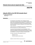
2.1 Simplified EVB Layout
Figure 1 illustrates how the evaluation board is laid out.
Designing Expansion Boards for the Motorola MPC555EVB/ETAS ES2000
Revised 15 January 1999
For More Information On This Product,
Go to: www.freescale.com
2
Freescale Semiconductor, Inc.
SW102
A
BDM
–
+
B
1
A
B
SW101
SW200
0
23
MODCK
FLASH
SRAM
POWER
CLAMP
STANDBY
(YELLOW)
MPC555
PAL
SRAM
POWER
POWER ON
Freescale Semiconductor, Inc...
0
7
SW305
8
15 16 23 24 31
(GREEN)
8
703
RESET
702
SW304 SW303 SW302
RESET CONFIGURATION WORD
VPP5
ON
1
VPP12
SW100
Figure 1 Evaluation Board Layout
2.2 Required Equipment
To perform the examples included in this application note, this equipment is needed:
• MPC555 evaluation board with MPC555 microcontroller
• 12-volt power supply capable of 1A (7- to 36-V allowable voltage input range)
• IBM-compatible PC with Software Development Systems’ SingleStep on-chip debugger,
BDM 5XX for PowerPC, MPC555 software
• Macraigor parallel to BDM interface, supplied with SDS’s debug software
• Oscilloscope
• Interconnect jumper to connect two pins
NOTE
This document assumes that the reader is using the SDS SingleStep debug software tool. If another software tool is used, substitute read and write for the
appropriate commands in the examples.
2.3 Set Up and Initialization of the Evaluation Board
2.3.1 Initial Switch Positions
To set up the board for use in background debug mode (BDM), ensure that all the switches and jumpers
Designing Expansion Boards for the Motorola MPC555EVB/ETAS ES2000
Revised 15 January 1999
For More Information On This Product,
Go to: www.freescale.com
3
Freescale Semiconductor, Inc.
are in their correct positions before turning on the board. Use the simplified MPC555 EVB circuit diagram in Figure 1 to find the appropriate switch locations.
SW100:
Freescale Semiconductor, Inc...
1.
2.
3.
4.
5.
6.
7.
8.
OFF = External (TI) flash program (12-V) voltage = 0 V (flash programming is disabled.)
ON = VPP 12-V auto (software switchable)
OFF = MPC555 VPP = 5 volts disabled for programming MPC555 internal flash
OFF = MPC555 can be programmed (programming protect)
NC
ON = External bus / EXTBUS = 0
ON = Reset configuration enabled
ON = BDM enabled, power-up in BDM
SW101:B = BDM VFLS [0:1]
SW102:A = BDM mode
SW200:0101 sets clock speed to 4 MHz in limp mode
SW302-5 reset configuration word
Application Note
NOTE
Bit numbers are marked on the PC board, NOT on the switch; up is ON (1).
Table 1 Reset Configuration Word
SW305
0
00
SW304
7
01
00
00
8
01
SW303
15
00
00
00
16
00
SW30
23
00
10
00
24
00
31
00
00
00
SW702 — Push button = hard reset (HRESET)
SW703 — ON/STBY = ON: All power supplies are on
STBY — V DD SRAM and KAPWR are left on
2.3.2 Powering on the Evaluation Board
DC power supply should be capable of 12 volts (7-36 volts) and 1A. To turn it on:
1. Connect the power leads to the EVB using the two clamp connectors shown in Figure 1 (in the
top right hand corner of the EVB). Be sure to observe voltage polarity specifications.
2. Turn on the power supply to 12 volts. Make sure the yellow standby LED (light emitting diode)
is lit.
3. To turn on the evaluation board and start the microcontroller, throw the toggle switch (SW702)
next to the green LED. Note that the green LED should light up after the switch is thrown.
4. The MPC555 defaults to 20 MHz on the MPC555 EVB.
2.3.3 Description of LEDs on the EVB
The evaluation board has four LEDs mounted on it, two of them red and one each green and yellow.
(See the part numbers on the board in brackets.) They are:
1. Red (LD701) — VPP 12 volts available for flash programming
2. Red (LD700) — VPP 5 volts available for flash programming
3. Green (LD702) — Evaluation board is on and MPC555 is out of RESET.
Designing Expansion Boards for the Motorola MPC555EVB/ETAS ES2000
Revised 15 January 1999
For More Information On This Product,
Go to: www.freescale.com
4
Freescale Semiconductor, Inc.
4. Yellow (LD703) — DC power is available and the board is in standby mode
3 Installing the Software Tools and Interface
NOTE
These instructions describe the installation and use of SDS debug version 7.3
beta or later using a Macraigor wiggler (interface). Refer to the instructions of the
particular tool that is being used.
3.1 Installing SDS Debug on a PC
For the MPC555, SingleStep version 7.3 beta or above of the software is required. A license from SDS
is required to run this software. This will either be provided on a disk or by email. Create the license.dat from the email and keep it handy for the installation.
Freescale Semiconductor, Inc...
To install:
1.
2.
3.
4.
Insert the SDS SingleStep debug CD-ROM into the CD drive.
Choose RUN from the File or Start menu.
Type D:\setup and press <RETURN> (where D: is the CD drive).
Follow the installation instructions and insert the disk containing the license.dat file when
prompted. Select the PowerPC MPC555 set of tools.
Next, create and install the configuration files for the MPC555 evaluation board. These commands will
set up some aliases and chip selects for the external flash and SRAM on the EVB.
1. Create a directory called MPC555 under the SDS73 directory.
2. Using a text editor, create a file containing the following text and name the file sstep.ini.
# This "sstep.ini" file is provided for supporting the
# Motorola MPC555 on the MPC555 EVB
# for BDM5xx
# Set JTAG speed for top performance
set jtag_speed = 1
# _reset alias requirements:
# Initialize PC, Stack and LR
# Set MSR[RI] so that Hardware Breakpoints work
# Set MSR[FP] floating point available____
alias _reset '@ PC = &START ; @ SP = &STKTOP ; @ LR = 0x0 ; \
@ MSR = ( $MSR | 0x02002 )'
# Set up the board configuration
alias _config "source ${cmdpath}..\mpc555\m555.dbg"
The last section of this file instructs SDS SingleStep to use the file m555.dbg to set up the MPC555
EVB with the correct chip selects.
3. Save the text file sstep.ini in the mpc555 directory created earlier.
4. Next, use the following text to create the m555.dbg file and save it in the mpc555 directory
also.
NOTE
This initialization code sets up several options that will not be used in this application note. They are listed here for completeness and for future reference. This
code is only applicable to the MPC555 EVB. A complete list is given in section 7.2
Initialization Code for MPC555 on the MPC555 EVB. Any line starting with #
(the pound sign) is comment and does not have to be included in the file.
Designing Expansion Boards for the Motorola MPC555EVB/ETAS ES2000
Revised 15 January 1999
For More Information On This Product,
Go to: www.freescale.com
5
Freescale Semiconductor, Inc.
Freescale Semiconductor, Inc...
# This file sets up a basic board initialization of
# MPC555 EVB (Motorola/ETAS) evaluation board.
# From Version 1.1 Randy Dees September 7, 1998
# References to the MPC555 User's Manual reference
# the September 2, 1998 version of the UM.
#
#*************** SYPCR **********************************
# turn off the software watchdog timer,
# bus monitor is on in BDM mode, so set time out
# this register is write once after power on reset
# (see table 6-13 of the MPC555 User Manual)
write -l 0x2fc004 = 0x0000ff00
#
#
#
#
enable the following line and disable the previous line
to enable the software watchdog with a long time-out
(see table 6-13 of the MPC555 User Manual)
write -l 0x2fc004 = 0xFFFFFF03
#*************** BR0/OR0 *********************************
# Set up the TI flash chip select and options br0 & or0
# single read access, 32-bit access, 1M block, 5 wait states
# (see table 10-7 & 10-8 of the MPC555 User Manual)
# base address is 0x00800000
write -l 0x2fc104 = 0xfff00050
write -l 0x2fc100 = 0x00800003
#*************** TI Flash *********************************
# Initialize the TI flash DCR register
# set up extended pin set, 3 blocks, and place
# device into normal read mode.
write -l 0x800000 = 0x96
write -l 0x800000 = 0x5b
write -l 0x800000 = 0xFF
#*************** BR1/OR1 *********************************
# Set up the SRAM chip select and option register br1 & or1
# single read, 4M address space, 0 wait states
# EVB555 uses 1M for external SRAM,
# 1M for PRU
# 1M for optional HCE board,
# 1M for optional ETK SRAM
# (see table 10-7 & 10-8 of the MPC555 User Manual)
# base address is 0x00C00000
write -l 0x2fc10c = 0xffc00000
write -l 0x2fc108 = 0x00C00003
NOTE
These three switches can be used with the write and read commands:
- -b byte read/write
- -w 16-bit half word
- -l 32-bit word
Designing Expansion Boards for the Motorola MPC555EVB/ETAS ES2000
Revised 15 January 1999
For More Information On This Product,
Go to: www.freescale.com
6
Freescale Semiconductor, Inc.
5. Create a new short cut for the SDS SingleStep program (bdmp58.exe) and use the /sds73/
mpc555 directory as the Start In: directory under the short cut tab. This completes the setup
of the SDS software for the MPC555 EVB.
Once the software is installed, the user is ready to attach the BDM interface. Supplied with the SDS
SingleStep on-chip debugger software will be a parallel-to-serial interface specifically for the MPC5xx
series of microcontrollers. This interface is necessary to allow your PC to communicate via its parallel
port to the BDM port on the EVB.
3.2 Connecting the EVB to a PC
Freescale Semiconductor, Inc...
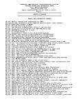
Refer to Figure 1 and Figure 2 when following these steps:
1. To the parallel port on the PC, connect a cable with a male 25-pin D-SUB connector on the other end.
2. To the male end, attach the Macraigor BDM interface, ensuring that the D-SUB connector is
secured firmly.
3. Attach the ribbon cable at the opposite end of the interface to the evaluation board using the
10-pin, 2-row header (Berg BDM connector) in the top right corner of the board (see Figure 1
and Figure 2).
NOTE
The connector at the end of the ribbon cable is keyed so that it can only fit correctly, but it must be pushed down all the way for an adequate connection.
4. With the PC connected to the interface and the interface attached to the evaluation board, connect the power transformer to an AC outlet.
Designing Expansion Boards for the Motorola MPC555EVB/ETAS ES2000
Revised 15 January 1999
For More Information On This Product,
Go to: www.freescale.com
7
Freescale Semiconductor, Inc.
POWER
RIBBON
CABLE
MPC 5XX
BDM
Freescale Semiconductor, Inc...
PARALLEL
PORT
SW102
A
BDM
–
+
B
1
A
B
SW101
SW200
0
23
MODCK
FLASH
SRAM
POWER
CLAMP
STANDBY
(YELLOW)
MPC555
PAL
SRAM
POWER
POWER ON
0
7
SW305
8
15 16 23 24 31
(GREEN)
703
8
RESET
702
SW304 SW303 SW302
RESET CONFIGURATION WORD
VPP5
ON
1
VPP12
SW100
Figure 2 BDM Interface Connection
NOTE
Remember to connect the interface box power supply and make sure that the ribbon cable connector is correctly aligned with pin 1 on the left.
4 Initializing the Hardware
With the software installed and the BDM interface (sometimes called a wiggler) connected and powered, turn on the MPC555 evaluation board and make sure the green LED is lit.
Designing Expansion Boards for the Motorola MPC555EVB/ETAS ES2000
Revised 15 January 1999
For More Information On This Product,
Go to: www.freescale.com
8
Freescale Semiconductor, Inc.
4.1 Starting SDS SingleStep Debug
Freescale Semiconductor, Inc...
Follow these steps in order to start the SingleStep debug.
1. Start the SDS SingleStep on-chip software. A tabbed dialogue will be shown.
2. Under the “File” tab, select the “Debug without a file” radio button.
3. Choose the “Processor” tab and select MPC555 from the drop-down list. There is no co-processor.
4. Click on OK and the PC will connect to the MPC555. Look for “Started Successfully” in the debug session dialogue box. Choose Close. If the MPC555 needs to be reconnected, start the
debug session again by selecting “Debug...” from the File menu.
5. From the “Window” drop down menu, select the “Command” window. There should be a window with a “SingleStep>” prompt. This interface will be used to write to and read registers on
the microcontroller. It is particularly useful because it can execute script files that can contain
series of commands and programs that are run on the microcontroller. The microcontroller can
also return output to this window. The “Command” window will be used to create and measure
the example signals.
4.2 Initializing the EVB
Use SDS debug to initialize the MPC555 microcontroller by writing to registers that set bus speeds and
timers. Write a file using a text editor and save this code so that it can be used again without re-entering
it all.
1. Copy the following into a text editor. (References in brackets are to tables in the MPC555 User’s
Manual). Any line that begins with # is comment and does not have to be in the initialization file.
# Set IMB to full speed — can only be set back to the default
# half speed with a hard reset on power up
# (Table 12-6)
write -l 0x307f80=0x0
# Turn on the time base for interrupt generation
# (Table 6-16)
write -w 0x2fc200 = 0x0001
# The slew rate and weak pull-up / pull-down on some pins can
# be adjusted. Here we set the MIOS pins for a fast slew rate.
# (default is 200 ns)
# (Table 2-3)
write -l 0x2fc03c = 0x13000000
2. Save this file as init.dbg in a suitable directory.
3. To load and execute the file just created, type the following in the “Command” window and hit
return:
SingleStep> C:\”yourdirectory”\init.dbg
This file will prepare the MPC555 to generate and measure signals.
5 Using the MPC555 as a Signal Generator
One of the MIOS features introduced in section 5.2 Programming the PWM is the pulse width modulator (PWM). The PWM can be used to generate waves of varying frequencies and duty cycles. The first
example in this application note explains how to generate signals with frequencies of 5 MHz and 2.5
MHz, and an oscilloscope is used to look at the signals and measure their frequencies.
Designing Expansion Boards for the Motorola MPC555EVB/ETAS ES2000
Revised 15 January 1999
For More Information On This Product,
Go to: www.freescale.com
9
Freescale Semiconductor, Inc.
5.1 Attaching the Oscilloscope
Attaching two oscilloscope probes to the PWM channels might be the hardest part of this exercise. The
easiest way to get to the PWM channels is through the MAPI ring connector on the underside of the
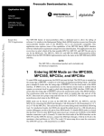
evaluation board (see Figure 3). Although the signals are present on the board’s surface, high density
Mictor connectors are needed that would not be appropriate for this application.
On the underside of the evaluation board are five brown, 100-pin Robinson Nugent connectors labelled
J1/P1 through J4/P4. (The fifth connector is an extension of the MAPI ring, MAPI 400 +100). The PWM
channels are on the J1/P1 connector. This example uses channels PWM 0 and PWM 2 (to allow space
between the contacts so that probe tips can be attached without conflict). PWM 0 is on pin 30 and PWM
2 is on pin 36 of J1/P1.
Freescale Semiconductor, Inc...
1. Attach oscilloscope channel 1 to pin 30 of connector J1/P1.
2. Attach oscilloscope channel 2 to pin 36 of connector J1/P1.
PROBES
1 (PIN 30)
2 (PIN 36)
100
PIN 1
2
J1/P1
PIN 21
99
PIN 1
J4/P4
MPC555 (ON OTHER SIDE)
J2/P2
J3/P3
Figure 3 Underside of MPC555 EVB
5.2 Programming the PWM
The PWM can be initialized by setting up the appropriate registers. The MPC555 has eight channels
that can be used as modulators. Two are used here, channels 0 and 2. The PWM channels are controlled by one system register and four registers that are unique to each channel.
5.2.1 PWM Reference Clock
Figure 4 shows how the MPC555 references events in the PWM to the rest of the system.
Designing Expansion Boards for the Motorola MPC555EVB/ETAS ES2000
Revised 15 January 1999
For More Information On This Product,
Go to: www.freescale.com
10
Freescale Semiconductor, Inc.
Application Note
PROBES
1 (PIN 30)
2 (PIN 36)
100
PIN 1
2
J1/P1
PIN 21
99
PIN 1
Freescale Semiconductor, Inc...
J4/P4
MPC555 (ON OTHER SIDE)
J2/P2
J3/P3
Figure 4 PWM Clock Arrangement
The eight pulse width modulators are part of the MIOS submodule on the MPC555. To use the PWM
channels, the MIOS counter must be started. Normally, the IMB (intermodule bus) clock is half the system clock, but for this example it has to be set to full speed at 20 MHz in the initialization script. This
was done to maintain consistency if the system clock is set to 40 MHz with a default half speed bus of
20 MHz. The IMB can be set to 20 MHz whether the MPC555 is operating at 20 or 40 MHz.
The MIOS counter prescaler submodule (MCPSM) divides the system IMB clock (20 MHz for this note)
to generate the counter clock. It is designed to provide all the submodules with the same division of the
main clock. The clock signal is prescaled by loading the value of the clock prescaler register into the
prescaler counter every time it overflows. This allows all prescaling factors between 2 and 16. Counting
is enabled by asserting the PREN bit in the control register.
NOTE
Because the PWM uses the MIOS counter to time itself, the maximum frequency
that the PWM can generate is half of the MIOS counter clock, even if the PWM
channel divider is set to 1. This is because the PWM uses 1 count of the MIOS
counter per transition of the PWM signal.
The IMB bus speed register was programmed to full speed in the initialization of the MPC555. (If the
MPC555 is running at 40 MHz, comment that line out of the initialization code (see section 4.2 Initializing the EVB) and power-on reset the evaluation board so that the IMB bus is operating at 20 MHz.)
The next step is to set up the MIOS counter.
The MIOS counter prescaler submodule (MCPSM) is controlled by the MCPSM status/control register.
The information in Figure 5 explains the bit assignments for the status/control register.
Designing Expansion Boards for the Motorola MPC555EVB/ETAS ES2000
Revised 15 January 1999
For More Information On This Product,
Go to: www.freescale.com
11
Freescale Semiconductor, Inc.
MSB
0
1
2
PREN
FREN
3
4
5
6
7
8
9
10
11
12
13
Reserved
14
LSB
15
0
0
PSL
RESET:
0
0
0
0
0
0
0
0
0
0
0
0
0
0
Figure 5 MCPSM Status/Control Register (MCPSMSCRT) 0x30 6816
The bit settings are explained in Table 2.
Freescale Semiconductor, Inc...
Table 2 MCPSMSCR Bit Settings
Bit(s)
Name
Description
0
PREN
Prescaler enable. This active high read/write control bit enables the MCPSM counter. The PREN
bit is cleared by reset.
0 = MCPSM counter disabled
1 = MCPSM counter enabled
1
FREN
Freeze enable. When set, this active high read/write control bit makes possible a freeze of the
MCPSM counter if the MIOB freeze line is activated. Note that this line is active when the
MIOS1MCR STOP bit is set or when the MIOS1MCR FREN bit and the IMB3 FREEZE line are
set.
When the MCPSM is frozen, it stops counting. Then when the FREN bit is reset or when the
freeze condition on the MIOB is negated, the counter restarts from where it was before being
frozen. The FREN bit is cleared by reset.
0 = MCPSM counter not frozen
1 = Selectively stops MIOS1 operation when the FREEZE signal appears on the IMB3
2:11
—
12:15
PSL
Reserved
Clock prescaler. This 4-bit read/write data register stores the modulus value for loading into the
clock prescaler. The new value is loaded into the counter the next time the counter equals one
or when disabled (PREN bit = 0). Divide ratios are as follows:
0000 = 16
0001 = No counter clock output
0010 = 2
0011 = 3
.
.
.
1110 = 14
1111 = 15
Following the register description and the information in Table 2, set bit 1 high to enable the counter
and write 0010 to bits 12 to 15 to set the divider to 2 for the fastest counter possible. The faster the
counter, the faster the waveforms that can be produced. All other bits should be 0.
Converting these binary bits to hex (use Table 9, if necessary), 0x8002 must be written to register
0x306816 (MCPSMCR).
Designing Expansion Boards for the Motorola MPC555EVB/ETAS ES2000
Revised 15 January 1999
For More Information On This Product,
Go to: www.freescale.com
12
Freescale Semiconductor, Inc.
• Type this line into the SDS command window:
write -w 0x306816 = 0x8002
Next, the individual PWM channels must be programmed.
5.2.2 PWM Period Register (MPWMSMPERR)
The MPWMSMPERR sets the number of divisions per period of the waveform, for example, resolution
of a single period.
Freescale Semiconductor, Inc...
Special consideration must be taken when choosing the resolution of the wave to be produced because
it involves a compromise. The resolution of the wave is inversely proportional to the maximum frequency that can be produced. Higher resolution requires more cycles of the reference clock per period and,
therefore, a lower overall frequency. (See section 5.2.1 PWM Reference Clock.) The contents of the
period register contain the binary value corresponding to the number of MIOS clocks allocated to the
period of the waveform.
PWM channels 0 and 2 will be programmed with the same period resolution:
• Type this line for channel 0:
write -w 0x306000 = 0x0002
• And the following for channel 2:
write -w 0x306010 = 0x0002
5.2.3 PWM Pulse Register (MPWMSMPULR)
This register sets the number (in binary) of divisions from section 5.2.2 PWM Period Register (MPWMSMPERR) that are high. This means that the ratio of the pulse register to the period register determines the duty cycle of the produced signal. The value in the pulse register must be less than the value
contained in the period register.
• Type this line for channel 0 for a 50 percent duty cycle.
write -w 0x306002 = 0x0001
• Do the same for channel 2:
write -w 0x306012 = 0x0001
5.2.4 PWM Status/Control Register (MPWMSMSCR)
The last eight bits of this register (MPWMSMSCR) set the clock divider for the particular PWM channel.
This divider operates on the MIOS clock whose frequency was set in 5.2.1 PWM Reference Clock.
Each PWM channel can use a divider to slow the MIOS counter clock.
NOTE
Remember that this will also affect the period and pulse width registers. Figure 6
shows the bit assignments for this register and Table 3 describes the assignments.
Designing Expansion Boards for the Motorola MPC555EVB/ETAS ES2000
Revised 15 January 1999
For More Information On This Product,
Go to: www.freescale.com
13
Freescale Semiconductor, Inc.
MSB
0
1
2
3
4
5
PIN
DDR
FREN
TRSP
POL
EN
0
0
0
0
6
7
8
9
10
11
Reserved
12
13
14
LSB
15
U
U
U
U
CP
RESET:
—
0
0
0
U
U
U
U
Figure 6 MPWMSW Status/Control Register (MPWMSMSCR) 0x30 6006
Freescale Semiconductor, Inc...
e
Table 3 MPWMSMSCR Bit Settings
Bit(s)
Name
Description
0
PIN
Pin input status. The PIN bit reflects the state present on the MPWMSM pin. The
software can thus monitor the signal on the pin.
1
DDR
The PIN bit is a read-only bit. Writing to the PIN bit has no effect.
Data direction register. The DDR bit indicates the direction for the pin when the
PWM function is not used (disable mode). Note that when the PWM function is
used, the DDR bit has no effect.
0 = Pin is an input.
1 = Pin is an output.
2
FREN
Freeze enable. This active high read/write control bit enables the MPWMSM to
recognize the freeze signal on the MIOB.
0 = MPWMSM is not frozen even if the MIOB freeze line is active.
1 = MPWMSM is frozen if the MIOB freeze line is active.
3
TRSP
Transparent mode. The TRSP bit indicates that the MPWMSM double buffers are
transparent: when the software writes to either the MPWMA or MPWMB1 register
the value written is immediately transferred to respectively the counter or register
MPWMB2.
0 = Transparent mode deactivated.
1 = Transparent mode activated.
4
POL
Output polarity control. The POL bit works in conjunction with the EN bit and controls whether the MPWMSM drives the pin with the true or the inverted value of
the output flip-flop
5
EN
Enable PWM signal generation. The EN bit defines whether the MPWMSM generates a PWM signal or is used as an I/O channel:
0 = PWM generation is disabled (pin can be used as I/O).
1 = PWM generation is enabled (pin is output only).
6:7
—
Reserved
8:15
CP
Clock prescaler. This 8-bit read/write register stores the twos complement of the
desired modulus value for loading into the built-in 8-bit clock prescaler. The value
loaded defines the divide ratio for the signal that clocks the MPWMSM period
counter. Table 4 gives the clock divide ratio according to the CP values.
Bits 8 through 15 of this register determine the clock divider to be used. Table 4 describes the use of
these four bits.
Designing Expansion Boards for the Motorola MPC555EVB/ETAS ES2000
Revised 15 January 1999
For More Information On This Product,
Go to: www.freescale.com
14
Freescale Semiconductor, Inc.
Freescale Semiconductor, Inc...
Table 4 MMCSMCR CP and MPWMSMSCR CP Values
Prescaler Value (CP in Hex)
MIOS Prescaler Clock Divided By
FF
1
FE
2
FD
3
FC
4
FB
5
FA
6
F9
7
F8
8
.......
.......
02
254 (2^8 -2)(
01
01 255 (2^8 -1)
00
00 256 (2^8)n
Now, generate a 5-MHz signal on channel 0 and a 2.5-MHz signal on channel 2. If the intermodule bus
is operating at 20 MHz and that is divided by 2 to get a MIOS counter at 10 MHz, then set channel 0 to
divide the MIOS counter by 1, remembering that it takes two MIOS counts per PWM period.
Likewise, to get 2.5 MHz on channel 2, divide the MIOS counter by 2.
• Type this line for channel 0 (5 MHz):
write -w 0x306006 = 0x54ff
• And this one for channel 2 (2.5 MHz):
write -w 0x306016 = 0x54fe
Other frequencies also can be produced using Table 5. Remember, these values only apply for the simple 50 percent duty cycle waveforms that have been created thus far with the MIOS counter at 10 MHz.
Table 5 Sample Frequency Settings
Hex Bits
Frequency
OF
20 kHz
FO
305 kHz
F8
610 kHz
FA
833 kHz
FB
1 MHz
FC
1.25 MHz
FD
1.66 MHz
FE
2.5 MHz
FF
5 MHz
6 Programming the MDASM
6.1 Using the MPC555 as a Frequency Counter
As part of its modular input/output subsystem (MIOS), the MPC555 has a dual action submodule
(MDASM). The MDASM can make pulse width and period measurements. Also, it can be used to capture waveforms and generate single and continuous pulses. We will use the MDASM to measure the
period of the two waveforms that were generated earlier using the PWM.
Designing Expansion Boards for the Motorola MPC555EVB/ETAS ES2000
Revised 15 January 1999
For More Information On This Product,
Go to: www.freescale.com
15
Freescale Semiconductor, Inc.
6.2 Connecting PWM Channels to MDASM Channels
To measure the output of the PWMs with the MDASM, a signal must be sent from the PWM channel (in
this case channel 0 or channel 2) to the MDASM channel 11. Here, the frequency of PWM channel 0 is
measured. The PWM channels are pins 30 and 36 on J1/P1 on the MAPI connector. The MDASM channel is located on pin 21 of MAPI connector J2/P2.
• Using a jumper wire, connect J1/P1 pin 30 to J2/P2 pin 21. See Figure 3 for MAPI pin locations.
NOTE
It is a good idea to keep the oscilloscope connected to be sure that the signal is
getting to the MDASM.
Freescale Semiconductor, Inc...
6.3 Configuring MPC555 to Measure Waveform Periods
The MDASM channel to be used needs to be configured to measure the period of the signals. The number of counts that occurred during the period of the test signal will be read out of the register. This will
allow the user to calculate the period of the waveform.
6.4 Setting Up the MDASM Bus Counter
The MPC555 MIOS has a modulus counter submodule (MMCSM) which can be used as a free-running
counter to which events can be referenced as they are detected. It can be used for complex counting
and timing functions.
The MDASM and the MMCSM work together to measure inputted waveforms. For this example, the
counter will be set to be free running and to roll over automatically when it reaches its maximum value.
The counter is controlled by the MMCSM status/control register, shown in Figure 7 with its bit assignments.
MSB
0
1
2
3
4
PINC
PINL
FREN
EDGN
EDGP
0
0
0
5
6
CLS
7
8
9
10
11
—
12
13
14
LSB
15
U
U
U
U
CP
RESET:
—
—
0
0
0
U
U
U
U
Figure 7 MMCSM Status/Control Register (MMCSMSCR) 0x30 6036 and 0x30 60B6
The last four bits of this register are the clock prescaler, as shown in Table 6.
Designing Expansion Boards for the Motorola MPC555EVB/ETAS ES2000
Revised 15 January 1999
For More Information On This Product,
Go to: www.freescale.com
16
Freescale Semiconductor, Inc.
Table 6 MMCSMSCR Bit Settings
Bit(s)
Name
0
PINC
Clock input pin status. This read-only status bit reflects the logic state of the clock input pin.
1
PINL
Modulus load input pin status. This read-only status bit reflects the logic state of the modulus
load pin.
2
FREN
Freeze enable. This active high read/write control bit enables the MMCSM to recognize the
MIOB freeze signal.
3:4
Modulus load falling edge/rising edge sensitivity. These active high read/write control bits set
falling edge and rising edge sensitivity, respectively.
EDGN,
EDGP
Freescale Semiconductor, Inc...
5:6
Description
CLS
00 = Disabled
01 = MMCSMCNT load on rising edges
10 = MMCSMCNT load on falling edges
11 = MMCSMCNT load on rising and falling edges
Clock select. These read/write control bits select the clock source for the modulus counter.
00 = Disabled
01 = Falling edge of pin
10 = Rising edge of pin
11 = MMCSM clock prescaler
7
—
—
8:15
CP
Clock prescaler. This 8-bit read/write data register stores the twos complement of the desired
modulus value for loading into the built-in 8-bit clock prescaler. The new value is loaded into the
prescaler counter when the next counter overflow occurs or when the CLS bits are set to select
the clock prescaler as the clock source. Table 4 gives the clock divide ratio according to the CP
values
Set up the MDASM to count on rising edges (bits 3:4) and to use the MMCSM clock. The clock prescaler
is governed by the same values as the PWM prescaler bits listed in Table 4 in the PWM section. Set it
up to follow the MMCSM clock with a prescaler division of 1. This means that the counter will run at 10
MHz or 100 ns per count.
• Type this line to set up the MDASM counter:
write -w 0x306036 = 0x0eff
To ensure that the counter starts properly, reset it. To reset the counter, load all 0s into the modulus
latch register. This is a read/write register containing the 16-bit value of the counter used by the
MDASM.
• Type this line to reset the MDASM counter:
write -w 0x306032 = 0x0000
With the clock now running, the MDASM can be set up to detect the waveform periods and reference
them to this counter.
6.5 Configuring MDASM Channels
The MDASM must be initialized to the kind of function that the user wants it to perform. There are two
waveforms of 5 MHz and 2.5 MHz to measure. The user will measure the periods to calculate their frequencies and compare.
Similar to the pulse width modulator in the last example, each MDASM channel has its own configuration registers. In this case, only one channel is used.
Each MDASM channel is configured and read using four registers:
Designing Expansion Boards for the Motorola MPC555EVB/ETAS ES2000
Revised 15 January 1999
For More Information On This Product,
Go to: www.freescale.com
17
Freescale Semiconductor, Inc.
• Data A register — Contains a value for the counter when the last event occurred
• Data B register —Can contain the previous value of Data A or an independent measurement
• Duplicate status/control register — Reserved. Do not use.
• Status/control register — Contains a read-only bit reflecting the status of the MDASM pin as
well as read/write bits related to its
• control and configuration.
The MDASM status and control register (address 0x30605E) will be used to initialize MDASM channel
11. Figure 8 and Table 7 define the bits in this register.
MSB
0
1
2
3
4
PIN
WOR
FREN
0
EDPOL
0
0
0
5
6
FORCA FORCB
7
8
9
RESERVED
10
BSL
11
12
13
0
14
LSB
15
MOD
Freescale Semiconductor, Inc...
RESET:
—
0
0
0
0
0
0
0
0
0
0
0
0
Figure 8 MDASM Status/Control Register (MDASMSCR) 0x30 605E
Table 7 MDASMSCR Bit Settings
Bit(s)
Name
0
PIN
1
WOR
Description
Pin input status. The pin input status bit reflects the status of the corresponding pin.
Wired-OR. In the DIS, IPWM, IPM, and IC modes, the WOR bit is not used; reading this bit returns the value that was previously written. In the OCB, OCAB, and OPWM modes, the WOR
bit selects whether the output buffer is configured for open-drain or totem pole operation.
0 = Output buffer is totem pole.
1 = Output buffer is open-drain.
2
FREN
Freeze enable. This active high read/write control bit enables the MDASM to recognize the
MIOB freeze signal.
0 = The MDASM is not frozen even if the MIOB freeze line is active.
1 = The MDASM is frozen if the MIOB freeze line is active.
3
—
4
EDPOL
0
Polarity. In DIS mode, this bit is not used; reading it returns the last value written. In IPWM mode,
this bit is used to select the capture edge sensitivity of channels A and B.
0 = Channel A captures on a rising edge. Channel B captures on a falling edge.
1 = Channel A captures on a falling edge. Channel B captures on a rising edge.
In IPM and IC modes, the EDPOL bit is used to select the input capture edge sensitivity of channel A.
0 = Channel A captures on a rising edge.
1 = Channel A captures on a falling edge.
In OCB, OCAB, and OPWM modes, the EDPOL bit is used to select the voltage level on the
output pin.
0 = The output flip-flop logic level appears on the output pin: A compare on channel A
sets the output pin; a compare on channel B resets the output pin.
1 = The complement of the output flip-flop logic level appears on the output pin: A compare on
channel A resets output pin; a compare on channel B sets output pin.
Designing Expansion Boards for the Motorola MPC555EVB/ETAS ES2000
Revised 15 January 1999
For More Information On This Product,
Go to: www.freescale.com
18
Freescale Semiconductor, Inc.
Table 7 MDASMSCR Bit Settings (Continued)
Bit(s)
Name
Description
5
FORCA
Force A. In OCB, OCAB, and OPWM modes, the FORCA bit allows the software to force the
output flip-flop to behave as if a successful comparison had occurred on channel A (except that
the FLAG line is not activated). Writing a 1 to FORCA sets the output flip-flop; writing a 0 to it
has no effect.
In DIS, IPWM, IPM, & IC modes, the FORCA bit is not used; writing to it has no effect. FORCA
is cleared by reset and is always read as 0. Writing a 1 to both FORCA and FORCB simultaneously resets the output flip-flop.
Freescale Semiconductor, Inc...
6
FORCB
Force B. In OCB, OCAB, and OPWM modes, the FORCB bit allows the software to force the
output flip-flop to behave as if a successful comparison had occurred on channel B (except that
the FLAG line is not activated). Writing a 1 to FORCB resets the output flip-flop; writing a 0 to it
has no effect.
In DIS, IPWM, IPM, & IC modes, the FORCB bit is not used; writing to it has no effect. FORCB
is cleared by reset and is always read as 0. Writing a 1 to both FORCA and FORCB simultaneously resets the output flip-flop.
7:8
—
9:10
BSL
11
—
12:15
MOD
Reserved
Bus select.These bits are used to select which of the four possible 16-bit counter buses passing
nearby is used by the MDASM.
0
Mode select. These four mode select bits select the mode of operation of the MDASM. To avoid
spurious interrupts, it is recommended that MDASM interrupts are disabled before changing the
operating mode. It is also imperative to go through disable mode before changing the operating
mode. See Table 8 for details.
In programming the MDASM with register 0x30605E, notice that bit 0 in Table 7 is a read-only status
pin that toggles according to the status of the incoming waveform.
For input period measurement:
• Bits 1, 3, 5, 6, 7, 8, and 11 are not used. Write zeroes to these bits.
• Because the MDASM should not freeze in BDM, bit 2 will be left as 0.
• Bit 4 will be 0 to trigger the MDASM counter on the rising edge.
• Bits 9 and 10 select which 16-bit counter bus the MDASM will use. Write 00 to these two bits.
To perform frequency measurement, the input period (MOD 0010 in Table 8) must be measured. Then
convert this time measurement into frequency to compare with what is being sent to the MDASM.
Designing Expansion Boards for the Motorola MPC555EVB/ETAS ES2000
Revised 15 January 1999
For More Information On This Product,
Go to: www.freescale.com
19
Freescale Semiconductor, Inc.
Table 8 MDASM Mode Selects
MDASM Control
Register Bits
Bits
of Resolution
Counter Bus
Bits Ignored
MDASM Mode
of Operation
Freescale Semiconductor, Inc...
MOD
0000
—
—
DIS – Disabled
0001
16
—
IPWM – Input pulse width measurement
0010
16
—
IPM – Input period measurement
0011
16
—
IC – Input capture
0100
16
—
OCB – Output compare, flag on B compare
0101
16
—
OCAB – Output compare,
flag on A and B compare
0110
—
—
Reserved
0111
—
—
Reserved
1000
16
—
OPWM – Output pulse width modulation
1001
15
0
OPWM – Output pulse width modulation
1010
14
0,1
OPWM – Output pulse width modulation
1011
13
0-2
OPWM – Output pulse width modulation
1100
12
0-3
OPWM – Output pulse width modulation
1101
11
0-4
OPWM – Output pulse width modulation
1110
9
0-6
OPWM – Output pulse width modulation
1111
7
0-8
OPWM – Output pulse width modulation
• Load this line into the MDASM status/control register (MDASMSCR):
write -w 0x30605E = 0x0002
6.6 Obtaining Measurements in the MDASM Data Register
After capturing the data for one of the PWM channels, the value from the register can be read and the
period and frequency of the wave can be calculated.
When the MDASM detects a rising edge, it will write the value of the MMCSM counter to the DATA A
register for the MDASM channel. Upon detection of the next rising edge (one period later), the MDASM
will move the first counter value into DATA B register and write the new value to register A. In section
6.4 Setting Up the MDASM Bus Counter, the MMCSM was programmed to run at 10 MHz or to count
at 100 ns intervals. The subtraction of register B from register A will be the number of MMCSM counts
during one complete period of the input waveform.
• Type this line into the SDS command window:
read -l 0x306058
Using the -l command ensures that the contents of the two MDASM data registers are read at once so
that nothing is miscounted due to the time it takes to read the data out of memory on two successive
reads.
SDS will return eight hexadecimal characters in one longword, using the snapshot here:
SingleStep> read -l 0x306058
(0x306058)
00306058 ABCBABC9 00028002
.. .
Designing Expansion Boards for the Motorola MPC555EVB/ETAS ES2000
Revised 15 January 1999
For More Information On This Product,
Go to: www.freescale.com
20
Freescale Semiconductor, Inc.
.. .
.. .
NOTE
The user’s values may be different from these, since these are values read from a
free-running counter.
The longword ABCBABC9 contains the contents of the two data registers. DATA A contains ABCB, with
ABC9 in DATA B. Subtracting register B from register A (B –9 in hex), the answer is 2. To calculate the
frequency, multiply by 100 ns and take the reciprocal to get 5 MHz.
Freescale Semiconductor, Inc...
• Move the jumper wire to connect J1/P1 pin 36 to J2/P2 pin 21 and read the contents of the
register again as described earlier. The difference between the data registers should now be
4 MHz or 2.5 MHz.
Obtaining the values from the data registers of the MDASM completes the exercises in this application
note.
In these exercises, communication has been established between the software tool and the evaluation
board. The user also has verified that parts of the MPC555 are operating correctly.
7 Reference Information
7.1 Decimal to Binary to Hexadecimal Conversion Table
Table 9 Hex Conversion
Decimal
Hexadecimal
Binary
0
0
0000
1
1
0001
2
2
0010
3
3
0011
4
4
0100
5
5
0101
6
6
0110
7
7
0111
8
8
1000
9
9
1001
10
A
1010
11
B
1011
12
C
1100
13
D
1101
14
E
1110
15
F
1111
Designing Expansion Boards for the Motorola MPC555EVB/ETAS ES2000
Revised 15 January 1999
For More Information On This Product,
Go to: www.freescale.com
21
Freescale Semiconductor, Inc.
Freescale Semiconductor, Inc...
7.2 Initialization Code for MPC555 on the MPC555 EVB
7.2.1 sstep.ini file (in the /../sds73/mpc555 directory)
# This "sstep.ini" file is provided for supporting the
# Motorola MPC555 on the MPC555 EVB
# for BDM5xx
# Set JTAG speed for top performance
set jtag_speed = 1
# _reset alias requirements:
# Initialize PC, Stack and LR
# Set MSR[RI] so that Hardware Breakpoints work
# Set MSR[FP] floating point available
alias _reset '@ PC = &START ; @ SP = &STKTOP ; @ LR = 0x0 ; \
@ MSR = ( $MSR | 0x02002 )'
# Set up the board configuration
alias _config "source ${cmdpath}..\mpc555\m555.dbg"
7.2.2 m555.dbg file (in the /../sds73/mpc555 directory)
# This file sets up a basic board initialization of
# Motorola/ETAS EVB555 evaluation board. It can
# also initialize the MPC555 MSIL MPC555FADS board
# with changes noted below.
# Version 1.1 Randy Dees September 7,1998
# references to the MPC555 User's Manual reference
# the September 2,1998 version of the UM.
#
#*************** SYPCR **********************************
# turn off the software watchdog timer,
# bus monitor is on in BDM mode, so set time out
# this register is write once after power on reset
# (see table 6-13 of the MPC555 User Manual)
write -l 0x2fc004 = 0x0000ff00
# enable the following line and disable the previous line
# to enable the software watchdog with a long time-out
# (see table 6-13 of the MPC555 User Manual)
# write -l 0x2fc004 = 0xFFFFFF03
#*************** BR0/OR0 *********************************
# Set up the TI flash chip select and options br0 & or0
# single read access, 32-bit access, 1M block, 5 wait states
# (see table 10-7 & 10-8 of the MPC555 User Manual)
# base address is 0x00800000
write -l 0x2fc104 = 0xfff00050
write -l 0x2fc100 = 0x00800003
#*************** TI Flash *********************************
# Initialize the TI flash DCR register
# set up extended pin set, 3 blocks, and place
# device into normal read mode.
write -l 0x800000 = 0x96
write -l 0x800000 = 0x5b
write -l 0x800000 = 0xFF
#*************** BR1/OR1 *********************************
Designing Expansion Boards for the Motorola MPC555EVB/ETAS ES2000
Revised 15 January 1999
For More Information On This Product,
Go to: www.freescale.com
22
Freescale Semiconductor, Inc...
Freescale Semiconductor, Inc.
# Set up the SRAM chip select and option register br1 & or1
# single read, 4M address space, 0 wait states
# EVB555 uses 1M for external SRAM,
# 1M for PRU
# 1M for optional HCE board,
# 1M for optional ETK SRAM
# the MPCF555FADS board only requires 1M of address space
# change to write -l 0x2fc10c = 0xfff00000
# (see table 10-7 & 10-8 of the MPC555 User Manual)
# base address is 0x00C00000
write -l 0x2fc10c = 0xffc00000
write -l 0x2fc108 = 0x00C00003
#*************** BR2/OR2 *********************************
# these next lines set up set up chip select 2 for Altera
# br2 & or2 - this is the board configuration registers
# 32k block (MPC555FADS board only)
# (see table 10-7 & 10-8 of the MPC555 User Manual)
# base address is 0xFFFF8000
write -l 0x2fc114 = 0xffff8120
write -l 0x2fc110 = 0xFFFF8001
#*************** UMCR **********************************
# Set IMB to full speed -- this can only be set
# back to half speed with a hard reset.
# (see table 12-6 of the MPC555 User Manual)
write -l 0x307f80 = 0x0
#*************** TBSCR **********************************
# Turn on the time base, on during BDM freeze
# (see table 6-16 of the MPC555 User Manual)
write -w 0x2fc200 = 0x0001
#*************** PDMCR **********************************
# Set the slew rate of the MIOS pins to fast
# (default is 200ns rise/fall time)
# also turns off pull-up/down devices
# (see table 2-3 of the MPC555 User Manual)
write -l 0x2fc03c = 0x13000000
#*************** end of basic initialization *******************
7.2.3 init.dbg script
# Set IMB to full speed -- can only be set back to the default
#half speed with Power On Reset on power up
#(Table 12-6)
write -l 0x307f80=0x0
# Turn on the time base for interrupt generation
#(Table 6-16)
write -w 0x2fc200 = 0x0001
# Sets the slew rate of the MIOS to fast, 200 ns default
with Pull Up/Down resistors off.
#(Table 2-3)
write -l 0x2fc03c = 0x13000000
# To return to slow rise/fall time on MIOS
write -l 0x2fc03c = 0x03000000
Designing Expansion Boards for the Motorola MPC555EVB/ETAS ES2000
Revised 15 January 1999
For More Information On This Product,
Go to: www.freescale.com
23
Freescale Semiconductor, Inc.
Freescale Semiconductor, Inc...
7.2.4 Other Miscellaneous Initialization Registers for Reference
# Turn off serialization for benchmarking purposes
#Note that the ICTRL (SPR158) register defaults to 0 on reset
@ SPR158 = 0x7
#To verify:
echo $SPR158
# Set clock speed to 40 MHz
write -l 0x2fc284 = 0x0091c000
# Set clock speed to 20 MHz
write -l 0x2fc284 = 0x0041c000
7.3 Configuring the PWM Channels
# ALL CHANNELS
# Status and Control for MCPSM (main clock
# divider for MIOS i.e. main divider for all
# PWM's
write -w 0x306816 = 0x8002
###############################################################
#CHANNEL 0
# PWM Period Register (Resolution of waveform)
write -w 0x306000 = 0x0002
# PWM Pulse Width Register (How many periods -# from above-- that are high)
write -w 0x306002 = 0x0001
# PWM Status and control (Divider per PWM)
write -w 0x306006 = 0x54ff
###############################################################
#CHANNEL2
#PWM 2 Period Register
write -w 0x306010 = 0x0002
#PWM 2 Pulse width
write -w 0x306012 = 0x0001
#PWM 2 Status/Control Register
write -w 0x306016 = 0x54fe
7.4 MDASM Setup
#Counter Initialization
write -w 0x306036 = 0x0eff
#Reset counter latches
write -w 0x306032 = 0x0000
#Configure MDASM 11
write -w 0x30605e = 0x0002
#Reading MDASM 1 register A and B
#read -l 0x306058
8 How to Contact Software Development Systems
Software Development Systems, Inc., can be contacted at
333 E. Butterfield Road, Suite 700, Lombard, Ill. 60148;
1-800-448-7733; [email protected]; [email protected].
Designing Expansion Boards for the Motorola MPC555EVB/ETAS ES2000
Revised 15 January 1999
For More Information On This Product,
Go to: www.freescale.com
24
Freescale Semiconductor, Inc...
Freescale Semiconductor, Inc.
Designing Expansion Boards for the Motorola MPC555EVB/ETAS ES2000
Revised 15 January 1999
For More Information On This Product,
Go to: www.freescale.com
25
Freescale Semiconductor, Inc...
Freescale Semiconductor, Inc.
Designing Expansion Boards for the Motorola MPC555EVB/ETAS ES2000
Revised 15 January 1999
For More Information On This Product,
Go to: www.freescale.com
26
Freescale Semiconductor, Inc...
Freescale Semiconductor, Inc.
Designing Expansion Boards for the Motorola MPC555EVB/ETAS ES2000
Revised 15 January 1999
For More Information On This Product,
Go to: www.freescale.com
27
Freescale Semiconductor, Inc.
How to Reach Us:
Home Page:
www.freescale.com
Freescale Semiconductor, Inc...
E-mail:
[email protected]
USA/Europe or Locations Not Listed:
Freescale Semiconductor
Technical Information Center, CH370
1300 N. Alma School Road
Chandler, Arizona 85224
+1-800-521-6274 or +1-480-768-2130
[email protected]
Europe, Middle East, and Africa:
Freescale Halbleiter Deutschland GmbH
Technical Information Center
Schatzbogen 7
81829 Muenchen, Germany
+44 1296 380 456 (English)
+46 8 52200080 (English)
+49 89 92103 559 (German)
+33 1 69 35 48 48 (French)
[email protected]
Japan:
Freescale Semiconductor Japan Ltd.
Headquarters
ARCO Tower 15F
1-8-1, Shimo-Meguro, Meguro-ku,
Tokyo 153-0064
Japan
0120 191014 or +81 3 5437 9125
[email protected]
Asia/Pacific:
Freescale Semiconductor Hong Kong Ltd.
Technical Information Center
2 Dai King Street
Tai Po Industrial Estate
Tai Po, N.T., Hong Kong
+800 2666 8080
[email protected]
For Literature Requests Only:
Freescale Semiconductor Literature Distribution Center
P.O. Box 5405
Denver, Colorado 80217
1-800-441-2447 or 303-675-2140
Fax: 303-675-2150
[email protected]
Information in this document is provided solely to enable system and software
implementers to use Freescale Semiconductor products. There are no express or
implied copyright licenses granted hereunder to design or fabricate any integrated
circuits or integrated circuits based on the information in this document.
Freescale Semiconductor reserves the right to make changes without further notice to
any products herein. Freescale Semiconductor makes no warranty, representation or
guarantee regarding the suitability of its products for any particular purpose, nor does
Freescale Semiconductor assume any liability arising out of the application or use of
any product or circuit, and specifically disclaims any and all liability, including without
limitation consequential or incidental damages. “Typical” parameters which may be
provided in Freescale Semiconductor data sheets and/or specifications can and do
vary in different applications and actual performance may vary over time. All operating
parameters, including “Typicals” must be validated for each customer application by
customer’s technical experts. Freescale Semiconductor does not convey any license
under its patent rights nor the rights of others. Freescale Semiconductor products are
not designed, intended, or authorized for use as components in systems intended for
surgical implant into the body, or other applications intended to support or sustain life,
or for any other application in which the failure of the Freescale Semiconductor product
could create a situation where personal injury or death may occur. Should Buyer
purchase or use Freescale Semiconductor products for any such unintended or
unauthorized application, Buyer shall indemnify and hold Freescale Semiconductor
and its officers, employees, subsidiaries, affiliates, and distributors harmless against all
claims, costs, damages, and expenses, and reasonable attorney fees arising out of,
directly or indirectly, any claim of personal injury or death associated with such
unintended or unauthorized use, even if such claim alleges that Freescale
Semiconductor was negligent regarding the design or manufacture of the part.
AN1778
For More Information On This Product,
Go to: www.freescale.com