1
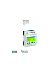
Telemecanique
Zelio-Logic
Smart Relay
User’s Guide
January 2000
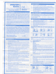
Preliminary Advice on Installing Smart Relays
Power down the device.
Take all necessary measures to avoid unwanted relay triggering.
Check to ensure that no voltage is present.
Make the necessary ground and short circuit connections.
Always follow the instructions stated in this user’s guide.
Remember, only qualified personnel are authorized to implement the
smart relay.
Automation and control devices must be installed so that they are
protected against any risk of involuntary actuation.
It is essential to ensure that all control system connections meet
applicable safety standards.
Fluctuations or variations in the mains supply voltage should not exceed
the tolerance thresholds stated in the technical characteristics, as they
may cause operating failures and lead to potentially dangerous
situations.
Take care to meet the standards that apply to emergency stop systems
in order to avoid potentially dangerous situations. Ensure that releasing
the emergency stop system does not cause the automated system to
suddenly restart.
Take all necessary measures to ensure that an application interrupted
by a drop or a break in the supply voltage can continue correctly and also
ensure that no dangerous states, no matter how brief, may occur.
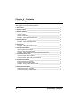
Contents
You wish to know how your new smart
relay works and discover its main
characteristics.
Powering up and Discovering
the Smart Relay
1
You require detailed information on, for
example, implementing a Ladder
diagram using a smart relay.
Implementing
a Typical Application
2
You would like to know all of the smart
relay’s configuration options.
Configuration Menu
3
Ladder Diagrams
4
Entering Ladder Diagrams
5
You would like to know what smart relay
control capability remains during
operation.
Debugging
6
You would like to improve your
understanding of the smart relay using a
complete example.
Application Example
7
You have an operating problem and you
would like to find the solution.
Troubleshooting
8
You would like to back up, transfer or
duplicate your application.
Transferring
Ladder Diagrams
9
Appendix
A
You would like to know all of the
elements in the Ladder diagram that are
recognized and used by the smart relay.
You would like to learn to enter a
complete Ladder diagram using the
smart relay.
You are looking for information:
Technical facts, Lexicon, Entry Forms.
You are looking for a specific word.
Smart Relay
Index
Index
Chapter 1 - Contents
Powering Up and Discovering the Smart Relay
This Chapter covers the following subjects:
1. Presentation ____________________________________________________ 3
2. Characteristics and Connections ___________________________________ 4
Characteristics ___________________________________________________ 4
Connections ____________________________________________________ 5
3. Command Keys __________________________________________________ 6
Description of the keys ____________________________________________ 6
4. Examples _______________________________________________________ 7
5. Main Functions _________________________________________________ 10
Main menu _____________________________________________________ 10
Configuration menu ______________________________________________ 11
2
Smart Relay - Chapter 1
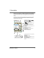
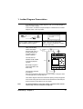
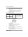
1. Presentation
Smart relays are designed to simplify the electrical wiring of intelligent
solutions. A smart relay is very simple to implement. Its flexibility and its
high performance allow users to save significant amounts of time and
money.
This User’s Guide is intended for people who do not have an in-depth
knowledge of automation systems and who would like to be able to
implement these smart relays.
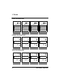
1
3
2
+
4
0V
I1
24VDC
I2
I3
5
I4
I5
I6
IB
IC
6
IB...IC =
inputs : analog
0...10VDC
or 24VDC
I1…I6 =
inputs 24 VDC
Ins. line
Del.
7
SR1 B121BD
z1
z4
8
z2
z3
9
Esc.
Sel./ OK
Output
4 x relay 240V / 10A
1
Q1
2
1
10
Q2
2
1
Q3
2
1
Q4
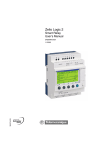
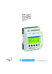
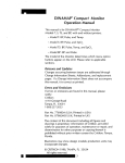
1-Retractable mounting feet
2-Power supply: 24 VDC for SR1z zz zBD,
100/240 VAC for SR1z zz zFU
3-LCD, 4 lines, 12 characters
4-Screw terminal block for 24 VDC inputs to
SR1z zz zBD, 100/240 VAC to
SR1z zz zFU
5-The SR1zz zzBD has analog 0-10 Volt
inputs usable in 24 VDC discrete mode
6-Delete key
7-Insert line key
8-Arrow keys or after first configuring them, Z
pushbuttons
9-Selection and validation key
10-Escape key
11-Connector for backup memory or PC
connection cable
12-Relay output terminal block
13-Slot for re-writable label.
11
2
1
13
12
1
2
3
4
5
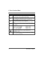
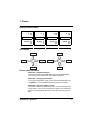
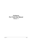
Smart Relay - Chapter 1
1-Input status display (B and C represent the
analog inputs)
2-Operating mode display
(RUN/STOP)
3-Parameter display, by default the day and
time for models with a clock
4-Output status display
5-Z key function display, when these keys are
activated.
3
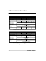
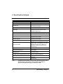
2. Characteristics and Connections
Characteristics
Product
References
Weekly clock
Supply voltage
Rated input current
Discrete inputs
Nbr.
Rated current
Rated voltage
Relay outputs
Nbr.
10 I/O
12 I/O
SR1-A101BD
SR1-B121BD
SR1-A201BD
20 I/O
SR1-B201BD
NO
YES
NO
YES
24 VDC (19.2 VDC min./30 VDC max.)
67 mA
6
6
12
10
3mA
24 VDC
4
8
5 ... 150 VDC /24 ... 250 VAC
AC 15 0.9 A/230 V DC 13 0.6 A/24 V
Voltage
Analog inputs 0-10V
Nbr.
0
2*
0
2*
* Each input is also usable in discrete I/O mode, 24 VDC
Product
References
Weekly clock
Alimentation
Rated input current
Discrete inputs
Nbr.
Rated current
Rated voltage
Relay outputs
Nbr.
Voltage
Note:
4
10 I/O
20 I/O
SR1-A101FU
SR1-B101FU
SR1-A201FU
SR1-B201FU
NO
YES
NO
YES
100/240 VAC (85 VAC min. /264 VAV max.)
< 46 mA at 115 VAC < 36 mA at 240 VAC
6
12
11/13 mA at 50/60 Hz
100/240 VAC
4
8
5 ... 150 VDC/24 ... 250 VAC
AC 15 0.9A/230V DC 13 0.6A/24V
AC smart relays do not have analog inputs. For further information,
refer to the Catalog.
Smart Relay - Chapter 1
2. Characteristics and Connections
Connections
Discrete inputs and outputs
Analog inputs
(1)
+
24 V
+ 24 VDC
I6 I7 I8
I1 I2 I3 I4 I5 I6 IB IC
I9 IA IB IC
…Inputs… IB…IC =
0…10 VDC or 24 VDC
I1…I6 …Inputs… IB…IC =
24 VDC
0…10 VDC or 24 VDC
a 0 -10 V ANALOG.
Ca / Ta
1
Ca / Ta
2
Fuse 1
+
24 V
-
1 Q3 2 1 Q4 2 1 Q5 2 1 Q6 2 1 Q7 2 1 Q8 2
1 Q1 2 1 Q2 2 1 Q3 2 1 Q4 2
(3)
12…240V
50 / 60 Hz
ou 12…125V
+ -
(4)
12…240V
50 / 60 Hz
SR1-z101BD
Inputs I1…I6 =
24 VDC
IB…IC =
0…10 VDC or 24 VDC
U
U
N/-
I1 I2 I3 I4 I5 I6 IB IC
24 VDC
(2)
L/+
12…125V
SR1-z201BD
(1)
L
100…240 V
50 / 60 Hz
N
L
N
I6 I7 I8
I1 I2 I3 I4 I5 I6
I9 IA IB IC
a 0 -10 V ANALOG.
100...240 VAC
I1…I6 =
inputs 100 240VAC
Ca / Ta
1
Ca / Ta
2
+
24 VDC
-
(3)
L/+
12…240 V
50 / 60 Hz
ou 12…125 V
+ -
I1 I2 I3 I4 I5 I6 IB IC
24 VDC
Inputs I1…I6 =
24 VDC
1 Q3 2 1 Q4 2 1 Q5 2 1 Q6 2 1 Q7 2 1 Q8 2
1 Q1 2 1 Q2 2 1 Q3 2 1 Q4 2
(4)
IB…IC =
0…10 VDC or 24 VDC
(2)
U
U
N/-
12…240 V
50 / 60 Hz
SR1-z101FU
12…125 V
SR1-z201FU
Three-wire connection
Fuse 1
+
24 V
BL
BN
BK
+ 24 VDC
Smart Relay - Chapter 1
BL
BN
BK
I1 I2 I3 I4 I5 I6 IB IC
Inputs I1…I6 =
24 VDC
IB…IC =
0…10 VDC or 24 VDC
5
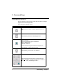
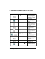
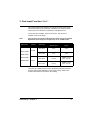
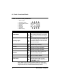
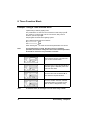
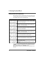
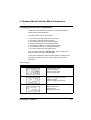
3. Command Keys
Description of the keys
The keys located on the front of the smart relay are used to configure,
program and control the application.
They perform the following actions:
Key
Description
Press this key to delete a Ladder diagram element or
line.
Press this key to insert a Ladder diagram line.
Press this key to:
Make a selection,
Enter the parameter page for an element,
Enter a display page,
Validate a selection.
To use the smart relay, the first action required is to
press this key to access the main menu.
Press this key to exit a menu or a selection.
The arrow keys are used to move up, left, down and
right. The position on screen is shown by a ">" index, a
"" or "z" cursor, the blinking text "Ini".
6
Smart Relay - Chapter 1
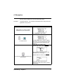
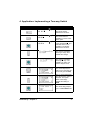
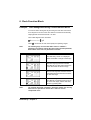
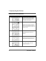
4. Examples
This sub-section details how to use the smart relay’s keys.
Example 1:
Language selection - The procedure described below is always the same,
regardless of the product.
Description/Action
Display
Initial power up or power up after
initialization by the manufacturer:
The "ENGLISH" option blinks.
+
To select French.
The Sel./ OK button is used to validate
the choice of a new language (as shown
by the lozenge symbol and by the text
blinking).
There are two possible cases:
Product with a clock, SR1-Bzzzzz
Now the time must be set (refer to the
example on the next page)
To continue or complete the initial power
up procedure.
Product without a clock, SR1-Azzzzz
The smart relay’s main screen is
displayed (in this case an SR1-A101FU
smart relay).
Smart Relay - Chapter 1
7
4. Examples
Example 2: Changing the date and time when first powered up.
Description/Action
Display/Comments
After choosing the language, the following
screen is brought up:
The black colored cursor blinks.
The text to change blinks ("WINTER" in
this case). You can then change it using:
To enter Modify mode.
or
then
Pressing Sel./OK validates the change.
The hours, minutes and day of the week settings can be changed in the
same way, using the smart relay keys.
To return to the main menu, press:
Note:
8
The
or
keys are used to move from one field to
another while the other two arrow key pad keys are used to change
the displayed values.
Smart Relay - Chapter 1
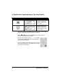
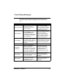
5. Main Functions
These are grouped in a main menu.
The ">" indicator located to the left of the text shows the setting of your
choice.
An upwards triangle indicates that there are more options available if you
scroll up, while a downwards triangle indicates that there are more
options available if you scroll down.
Smart Relay - Chapter 1
9
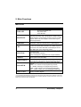
5. Main Functions
Main menu
Menu
TIME SET
PROGRAM.
PARAMET.
VISU.
RUN/STOP
CONFIG.
CLEAR PROG.
TRANSFER.
PROG. INFO.
Description
This function is used to set the date and time:
Summer time/Winter time
Day of the week
Hours-Minutes
This function lets the user enter the Ladder diagram that will
make the smart relay work. This program is written using a
Ladder diagram. For information on how to program a Ladder
diagram, refer to the next Chapter. This function may be
password protected.
This function lets the user display and change unlocked
parameters in elements entered in the Ladder diagram.
This function lets the user display and change unlocked
function block parameters entered in the Ladder diagram. It
also lets the user select data that will be displayed on the
third display line on the smart relay screen.
This function lets the user start or stop the program contained
in the smart relay:
RUN: the program is started.
STOP: the program is stopped and the outputs disabled.
This function comprises all of the smart relay configuration
options (refer to the next table).
This function will clear the entire Ladder diagram stored in
the smart relay. This function may be password protected.
This function will transfer the contents of the smart relay
memory.
Modul. -> PC: transfer to the programming software,
PC -> Modul.: loading by the programming software,
Modul. -> Mem: transfer to the unpluggable EEPROM*,
Mem -> Modul.: loading from the unpluggable EEPROM*.
This function will display all of the elements required for
entering a Ladder diagram.
* The unpluggable EEPROM allows transferring the contents of the smart relay memory without the need for the
programming software and without the need to enter an identical application in another smart relay. However, the
smart relay can still work without an EEPROM.
10
Smart Relay - Chapter 1
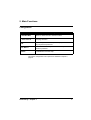
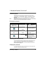
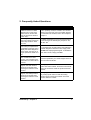
5. Main Functions
Configuration
Menu
Description
PASSWORD
Allows or denies access to certain functions.
LANGUAGE
Language selection.
Filt.
Input filtering mode selection (for fast inputs). This function
may be password protected.
Zx=KEYS
Enable/disable arrow keys Zx.This function may be
password protected.
HELP
Enable/disable automatic help.
The various configuration menu options are detailed in Chapter 3,
page 24.
Smart Relay - Chapter 1
11
Chapter 2 - Contents
Implementing a Basic Application
This Chapter covers the following subjects:
1. Ladder Diagram Presentation _____________________________________ 13
2. Using the Reverse Function _______________________________________ 14
Practical example _______________________________________________ 14
General case ___________________________________________________ 15
3. Notation Used by the Smart Relay _________________________________ 16
4. Application: Implementing a Two-way Switch ________________________ 18
Entering the Ladder Diagram ______________________________________ 18
12
Smart Relay - Chapter 2
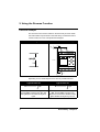
1. Ladder Diagram Presentation
If you already know how Ladder diagrams work, you can skip straight to
Section 3 of this Chapter.
In this section, we will use a simple example to understand how a Ladder
diagram works: a two-way switch.
Normal electrical diagram
Ladder diagram
I1 and I2 are two contacts representing
The two position switches identified as
VV1 and VV2 control the light L1.
inputs 1 and 2 on the smart relay.
Q1 is a coil that corresponds to output 1
from the smart relay.
Using a smart relay
means that simple
switches (with open or
closed positions) can
be used in place of
position switches.
The switches are
identified as S1 and S2
in the wiring diagram
opposite.
S1 are S2 conected to
inputs I1 and I2 on the
smart relay.
Fuse 1
L
100 ... 240 VAC
50 / 60 Hz
N
S1
L
N
100...240 VAC
S2
I1 I2 I3 I4 I5 I6
I1 ... I6 =
inputs 100 ... 240VAC
Fuse 2
1 Q1 2 1 Q2 2 1 Q3 2 1 Q4 2
The operating principle
L1
is as follows:
Each time inputs I1 and I2 change state, this causes a change in state
on output Q1 which controls lamp L1.
The Ladder diagram uses basic features like placing contacts in parallel
and in series along with the reverse function identified as i1 and i2 (the
reverse function is described on the next page).
Note:
The implementation of a two-way switch is optimum when remote
control relay coils are used (refer to page 33).
Smart Relay - Chapter 2
13
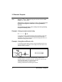
2. Using the Reverse Function
Practical example
The reverse function and its i notation in the smart relay is used to obtain
the reverse state of input I wired on the smart relay. To illustrate how this
function works, let us use a simple electrical diagram:
Electrical diagram
Connection to the smart relay
Fuse 1
L
100 ... 240 VAC
50 / 60 Hz
N
BP1
L
I1 I2 I3 I4 I5 I6
N
100...240 VAC
I1 ... I6 =
inputs 100 ... 240VAC
Fuse 2
1 Q1 2 1 Q2 2 1 Q3 2 1 Q4 2
L1
Depending on the Ladder diagram, there are two possible solutions:
Ladder diagram 1
Light out when idle
I1——————
Q1
I1 corresponds to the true image of BP1,
pressing BP1 activates input I1so that
the Q1output is activated and light L1
lights.
14
Ladder diagram 2
Light lit when idle
i1——————
Q1
i1 corresponds to the reverse image of
BP1, pressing BP1 activates input
I1therefore contact i1 is disabled, output
Q1is disabled and light L1 goes out.
Smart Relay - Chapter 2
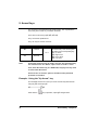
2. Using the Reverse Function
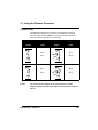
General case
The table below illustrates the operation of a pushbutton connected to
the smart relay. Pushbutton BP1 is connected to input I1 and the light
L1 is connected to output Q1 on the smart relay.
Idle
Electrical
diagram
Note:
Operating
Zelio
symbol
Electrical
diagram
Zelio
symbol
I1 = 0
I1 = 1
i1 = 1
i1 = 0
I1 = 1
I1 = 0
i1 = 0
i1 = 1
The reverse function applies to all of the contacts in a Ladder
diagram, whether they represent outputs, auxiliary relays or function
blocks.
Smart Relay - Chapter 2
15
3. Notation Used by the Smart Relay
The smart relay has a four line display used to show Ladder diagrams.
The table below shows the symbol notation used for basic elements.
Note:
The ZelioSoft application lets you represent Ladder diagrams in
three different formats
Ladder diagram
symbol
Zelio
symbol
I1 or i1
21
13
Electrical
symbol
or
22
14
ou
I1 or i1
"O"»
A1
"C"
A1
A2
Q1
Q1
R
Q1
A2
S
A2
A1
Set coil (SET)
Reset coil (RESET)
16
Smart Relay - Chapter 2
3. Notation Used by the Smart Relay
Other elements are also available using a smart relay:
Timer function block: used to delay, prolong and control an action for
a set length of time.
Counter function block: used to count the pulses received on an input.
Clock function block: used to trigger or release actions on precise days
or at precise times.
Analog comparator function block: used to compare an analog value
with a reference value or with another analog value after allowing for a
hysteresis factor.
Auxiliary relays: these are used to save or relay the startus of the smart
relay.
Z keys: after confirming this function, Z keys can be used as push
buttons.
Note:
For more information on all of the Ladder diagram elements
available when using a smart relay, refer to Chapter 4, page 30 for a
detailed description.
Smart Relay - Chapter 2
17
4. Application: Implementing a Two-way Switch
Entering the Ladder diagram
By following the indications in the table below, the user can enter the
two-way switch Ladder diagram.
From the main screen (the one shown on power-up), follow the
instructions shown in the "Action" column and press the specified
button.
The "Screen" button shows what the user will see on the smart relay
screen.
The "Comments" column provides some additional information on entry
and display actions.
Action
Screen
I1
I1
18
Comments
The main menu is
displayed, the " > " symbol
shows that the
"PROGRAM." option is
selected. This option
blinks.
After briefly displaying
"LINE 1" (for approx. 2
seconds), a blinking black
box is displayed.
The I blinks.
The smart relay prompts
the user to select the type
of contact.
The 1 blinks.
You have implicitly
selected a contact
assigned to an input (I),
the smart relay now
prompts you to select the
input number.
Smart Relay - Chapter 2
4. Application: Implementing a Two-way Switch
Action
Screen
I1
Comments
The blinks.
You have just validated
the contact entry to assign
to input I1. The is
moved ready to enter the
second contact.
The right hand I blinks.
The smart relay prompts
you to select the type of
contact.
I1—I1
I1—i1
The i blinks.
You have just selected the
reverse contact assigned
to an input.
I1—i1
The right hand 1 blinks.
Now enter the input
number.
I1—i2
The 2 blinks.
Now simply validate this
selection.
I1—i2
The blinks.
Move to the end of the line
ready to enter the coil.
ou
I1—i2
I1—i2
z
The z blinks, this indicates
a link point for linking
connections.
I1—i2————
Smart Relay - Chapter 2
The blinks.
Now enter the coil.
Q1
The Q blinks.
Now all that remains is to
select the other
parameters for this coil.
19
4. Application: Implementing a Two-way Switch
Action
Screen
Comments
I1—i2————
Q1
I1—i2————
Q1
I1—i2————
Q1
20
I1—i2————
I1
Q1
I1—i2————
i1
Q1
I1—i2————
i1
Q1
I1—i2————
i1
Q1
I1—i2————
i1—I1
Q1
I1—i2————
i1—I1
Q1
I1—i2————
i1—I2
Q1
The 1 blinks.
Coil Q is validated.
The
blinks.
The coil number is
validated.
The blinks.
The coil is validated based
on contact position.
The moves down a line
and the links are displayed
automatically.
The I located on the
second line blinks.
The i located on the
second line blinks.
The 1 located on the
second line blinks.
The blinks.
The I on the second line
blinks.
The second 1 in the
second line blinks.
The 2 in the second line
blinks.
Smart Relay - Chapter 2
4. Application: Implementing a Two-way Switch
Action
Screen
Comments
I1—i2————
i1 I2
Q1
The blinks.
Now enter the link
between the two lines.
I1—i2————
i1—I2 z
Q1
I1—i2————
i1—I2 +
Q1
The z blinks.
This shows that it is
possible to connect a link
at this point.
The + blinks.
It has replaced the z and
indicates that it is now
possible to set the link
between the two lines.
The contact point blinks
showing a + sign. Now
validate the change.
The contact point blinks
showing a z sign. The
validation is made, now
exit the diagram zone.
The screen displays the
main menu. Now start the
smart relay (Set to RUN).
Press three times
The ">" sign indicates that
the "RUN/STOP" option is
selected. This option
blinks. Now simply
validate the setting to
RUN.
The smart relay prompts
you to validate RUN mode.
Smart Relay - Chapter 2
21
4. Application: Implementing a Two-way Switch
Action
Screen
Comments
The smart relay is now set
to RUN. To monitor its
operation, return to the
main screen.
This screen lets the user
display two-way switch
operation (switch action,
indicator lights on or off,
light on or off).
This simple application example teaches the user how to enter a Ladder
diagram. The following points should be remembered:
When a or a z blinks, use the Sel/Ok button to add an element
(contact, coil or graphic link element).
When an element blinks (I, Q, N°, , …), it is possible
to use the Z1 and Z3 arrows on the arrow key pad to
select the required element.
It is also possible to use the Z2 or Z4 arrows on the key
pad to select the previous or next elements (or the next
part of the current element).
22
Smart Relay - Chapter 2
Smart Relay - Chapter 2
23
Chapter 3 - Contents
Configuration Menu
This Chapter covers the following subjects:
1. Password Function "PASSWORD" _________________________________ 25
Password purpose _______________________________________________
Entering the password ____________________________________________
Cancelling password protection _____________________________________
Changing the password ___________________________________________
25
25
25
25
2. Language Selection Function "LANGUAGE’" ________________________ 26
Using the "Ini." function ___________________________________________ 26
3. Fast Input Function "FILT." _______________________________________ 27
4. Arrow Keys Function "Zx=KEYS" __________________________________ 28
5. Help Function "HELP" ___________________________________________ 29
24
Smart Relay - Chapter 3
1. Password Function "PASSWORD"
Password purpose
Note:
The password secures access to the following main menu options:
"PROGRAM.", "CLEAR PROG", "FILT.", "Zx=KEYS", as well as
to the two application transfer options Module to PC and Module to
EEPROM.
This password comprises four digits from 0 to 9. It is entered using
the keys on the smart relay. By default it is disabled.
Entering the password
Action
Display
Select the "PASSWORD"
option from the
"CONFIG." menu.
PASSWORD
????
PASSWORD
0000
Enter the password using
the arrow keys Z1, Z2, Z3,
Z4.
PASSWORD
3020
PASSWORD
Comments
The
means that no
password is set yet.
The 0 on the right blinks.
Now enter the password.
The digit being changed
blinks. Now validate the
entry made.
This screen is displayed
for two seconds (the
password is activated)
and the user is returned to
the main menu.
Cancelling password protection
To cancel password protection, simply enter the current password (see
above). The password is inhibited and the smart relay displays a
transitory screen showing OFF. If you have forgotten your password,
refer to Chapter 8, page 71.
Changing the password
To change the password, simply cancel the former one and enter a new
one (refer to the method described above).
Smart Relay - Chapter 3
25
2. Language Selection Function "LANGUAGE"
This function lets the user choose the language used by the smart relay.
All messages can be displayed in six languages: English, French,
German, Italian, Spanish and Portuguese.
Example: Language selection screen.
In this example, French is chosen.
Note:
No language selection can be made with the smart relay in RUN.
Using the "Ini." function
When the Ini. function is selected, the next time the smart relay is
powered up, it prompts the user to select a language and enter the time
(for smart relays with a clock function).
26
Smart Relay - Chapter 3
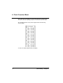
3. Fast Input Function "FILT."
This function allows faster detection of changes in states on the inputs.
This mode should only be used when necessary as it makes the smart
relay’s inputs more sensitive to interference and signal bounce.
Two choices are available: "FAST" and "SLOW". This function is
available on DC smart relays.
Note:
This selection can only be made when the smart relay is set to STOP.
By default, smart relays are configured to run in "SLOW" mode.
References
Filtering
SR1A121BD
Standard
discrete input
Analog
inputs
ON->OFF
5 ms
5 ms
OFF->ON
3 ms
3 ms
ON->OFF
0.5 ms
Rated: 0.3 ms
Max.: 0.5 ms
OFF->ON
0.3 ms
Rated: 0.2 ms
Max.: 0.3 ms
SLOW
SR1B121BD
SR1A221BD
SR1B221BD
Switching
FAST
The other (AC) modules only have one set filtering value that cannot be
changed and which is dependent on the supply voltage. Refer to the
technical characteristics provided in the Catalog.
Smart Relay - Chapter 3
27
4. Arrow Keys Function "Zx=KEYS"
The "Zx=KEYS" option lets the user enable or disable the use of arrow
keys as pushbuttons.
When these keys are disabled, they are only available for setting
parameters, configuring and programming the smart relay.
When these keys are enabled, it is also possible to use them in a Ladder
diagram.
They work like pushbuttons without the need to use a terminal block
input contact.
Representation
State
ZN°
Normally
open
zN°
Note:
28
Normally
closed
N°
Description
1 to 4
Representation of the smart relay’s
arrow keys, this contact shows the
state of the corresponding key.
Z1 Up arrow
Z2 Right arrow
Z3 Down arrow
Z4 Left arrow
By default this function is inactive.
Smart Relay - Chapter 3
5. Help Function "HELP"
This function lets the user enable or disable the automatic help function
when performing a smart relay parameter setting or programming action.
When the help function is enabled, simply remain on the required
element for a few seconds without pressing on a key and help will be
displayed in the form of an explanation screen.
To exit the screen, press on the
or
buttons.
Example of a help screen:
When setting function block parameters, holding position over the
padlock symbol will cause the "modif. param." message to appear.
Locking does indeed stop the function block from being displayed in the
parameter menu.
Smart Relay - Chapter 3
29
Chapter 4 - Contents
Ladder Diagrams
This Chapter covers the following subjects:
1. Introduction ____________________________________________________ 31
2. Discrete Inputs _________________________________________________ 32
3. Discrete Outputs ________________________________________________ 33
Used as a Coil __________________________________________________
Used as a Contact _______________________________________________
Example - Using a remote control relay ______________________________
Example - Using Set and Reset Coils ________________________________
33
33
34
34
4. Auxiliary Relays ________________________________________________ 35
Example - Using an Auxiliary Relay _________________________________ 35
5. Arrow Keys ____________________________________________________ 36
Example - Using the "Up Arrow" key _________________________________ 36
6. Clock Function Block ____________________________________________ 37
Clock function block contacts ______________________________________ 37
Clock function block parameters ____________________________________ 38
Example - Time management using a Clock function block _______________ 39
7. Counter Function Block __________________________________________ 41
Counter function block contacts ____________________________________ 41
Counter function block coils and parameters __________________________ 41
8. Timer Function Block ____________________________________________ 43
Timer function block contacts ______________________________________ 43
Timer function block parameters ____________________________________ 43
Example - Using a Timer function block ______________________________ 46
9. Analog Function Block ___________________________________________ 47
Analog function block contacts _____________________________________ 47
Analog function block parameters ___________________________________ 48
30
Smart Relay - Chapter 4
1. Introduction
This Section details all possible elements in a Ladder diagram that are
recognized and used by the smart relays. To better understand the
functions performed by each element, where necessary a directly usable
example is included.
The logic modules accept 60 line Ladder diagrams for 10 I/O smart
relays and 80 line ones for 20 I/O smart relays.
Note:
Each line comprises a maximum of three contacts and must include
a coil. When the application requires more than three contacts to
activate an action, the auxiliary relays can be used as shown in the
example below.
Ladder diagram example:
Smart Relay - Chapter 4
31
2. Discrete Inputs
A discrete input can only be used as a contact.
Representation
Function
N°
IN°
Normal
iN°
Reversed
1 to C
depends
on the
module
Description
The physical input to the smart relay.
This contact gives the state of the
sensor (switch, detector,…)
connected to the corresponding
input.
Example 1:
I1—————— Q1
When the input I1 contact is closed, output Q1 is activated.
Example 2:
i1—————— Q1
When the input I1 contact is not closed, output Q1 is activated.
32
Smart Relay - Chapter 4
3. Discrete Outputs
A discrete output can be used either as a contact or a coil.
Used as a coil
Usage
mode
Nbr. on
term. blk.
QN°
QN°
S QN°
1 to C
depends
on the
module
R QN°
Description
The coil is supplied if the contacts that it is connected to
are closed ones, else it is not supplied.
Pulse supply, the coil is supplied by a change of state.
This is the same as a remote control relay.
"Set" or triggered coil. This coil triggered as soon as the
contacts that it is connected to are closed. It remains
triggered even if the contacts are no longer closed.
"Reset" coil, also called a release coil. This coil is
disabled when the contacts that it is connected to are
closed. It remains idle even if the connects are no longer
closed.
Used as a contact
Representation
Function
N°
Description
QN°
Normal
qN°
Normally
closed
1 to 8
depending
on the
module
A physical output from the smart
relay.
An output can be used as a contact
to determine its state at a given time.
Example 1:
Q1—————— Q2
When output Q1 is activated, output Q2 is also activated.
Example 2:
q1—————— Q2
When output Q1 is disables, output Q2 is activated. Output Q2 will always take the
reverse state to output Q1.
Smart Relay - Chapter 4
33
3. Discrete Outputs
Note:
Using the
and
functions only once in each coil in a Ladder
diagram is recommended.
Additionally, if a SET coil (S function) is used, a line must always be
provided in the diagram to disable this coil using a RESET (R
function).
If not, then during operation, there is always the risk of generating
unexpected switching states.
Example - Using a remote control relay
I1——————
Q1
A very handy function, that allows lighting and extinguishing a light using
a pushbutton. If a pushbutton is connected to input I1 and a light to
output Q1, then each time the button is pressed, the light will come on if
it was off or it will go off if it was lit.
Example - Using Set and Reset coils
To control the power supply to a device using a pushbutton and to use a
second pushbutton to cut-off the power supply to the same device. The
following solution is applied:
Electrical diagram
Smart relay solution
Pushbutton BP2 is connected to the smart relay, to input I2, and
pushbutton BP3 is connected to input I3. The device to control, in this
case a light bulb called L1 is connected output Q2.
Pressing pushbutton BP2 will light the bulb.
Pressing pushbutton BP3 will extinguish the bulb.
34
Smart Relay - Chapter 4
4. Auxiliary Relays
The auxiliary relays, M in the notation used, operate just like the output
coils Q. The only difference is that they do not have any connection
terminals.
There are 15 auxiliary relays (numbered in hexadecimal notation from 1
to 9 and from A to F).
They are used to save or forward a state. This saved of forwarded state
will then be used as the assigned contact.
Example - Using an auxiliary relay
Using two auxiliary relays to save the position of a number of inputs. The
saved state is then used to control a coil.
This type of diagram is often used to control the various states of a
device.
Smart Relay - Chapter 4
35
5. Arrow Keys
The arrow keys work just like the physical inputs I. The only difference
is that they do not have any connection terminals.
There are four arrow keys (Z1, Z2, Z3, Z4).
They are used as pushbuttons.
They can only be used as contacts:
Representation
Function
ZN°
Normal
zN°
Note:
N°
Description
1 to 4
Representation of the arrow keys on
the smart relay. This contact gives
the state of the corresponding key.
Z1 Up arrow
Z2 Right arrow
Z3 Down arrow
Z4 Left arrow
Reverse
So that the arrow keys may be used in this way, first check that they
are activated in the "Zx=KEYS" option in the "CONFIG." menu.
If not, when the smart relay is in RUN mode, they keys are only used
to move within the menus.
Access to the "Zx=KEYS" option is locked out when password
protection is activated.
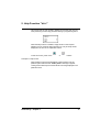
Example - Using the "Up Arrow" key
This example shows how to set up a remote control relay that will work
using key Z1 and output Q1.
36
Z1——————
Q1
Each time the
key is pressed, output Q1 changes state.
Smart Relay - Chapter 4
6. Clock Function Block
The Clock function block is used to validate time slots during which
actions can be performed. It acts just like a programmable weekly timer
and has four operating ranges (A, B, C, D) used to control its output.
The block’s parameter settings are accessible in two ways:
- When entering a diagram line,
- From the "PARAMET." menu, if the function block is not padlocked.
The following contacts can be used in a Ladder diagram:
Clock function block contacts
Representation
Function
N°
Normal
N°
Reverse
N°
1 to 4
Smart Relay - Chapter 4
Description
The contact is closed when the
Clock is in an enabled period.
The contact is closed when the
Clock is not in an enabled period.
37
6. Clock Function Block
Clock function block parameters
1 - Block number
2 - Operating ranges
3 - Current date and time
4 - Start day
5 - End day
6 - Start time
7 - Stop time
8 - Block locking
1
2
3
4
8
7
6
5
.
Parameter
Description
1
Four blocks can be used, numbered from
1 to 4. This parameter cannot be changed
in the screen shown above. It is chosen
when the block is entered in the diagram
line.
Operating ranges
2
Four operating ranges are available A, B,
C, D. During operation, these ranges are
cumulated: The block is valid over all of
the selected ranges.
Current date and time
3
Start day
4
This date corresponds to the day of the
week (Monday to Sunday).
For each range, a start of validity day
(Monday to Sunday) is specified.
End day
5
For each range, an end of validity day
(Monday to Sunday) is specified.
Start time
6
For each range, a start operating time
(00:00 to 23:59) is specified.
Stop time
7
Block locking
8
Block Number
For each range, a stop operating time
(00:00 to 23:59) is specified.
Each Clock block can be locked or left
unlocked. When locked, the Clock
function block no longer appears in the
"PARAMET." menu.
When validating the Clock block parameters (exiting the screen using
the ESC key), the smart relay displays a summary of the block’s validity
ranges so that the user can check the data that they entered.
38
Smart Relay - Chapter 4
6. Clock Function Block
Example - Time management using a Clock function block
To control a device during the day and using two time slots: from 09:00
to 13:00 and from 15:00 to 19:00. The device is connected to smart relay
output Q2 and Clock function block 1 is used.
The Ladder diagram line is as follows:
1——————
When
Note:
Q2
1 is entered, the user must specify the operating ranges.
The following keys are used: Sel./OK to select or validate a
parameter, Z1 and Z3 to change the value of the selected parameter,
Z2 and Z4 to move from one parameter to another.
Screen
Comments
First data entry screen. It is displayed
blank and is filled-in using the arrow keys.
The first range (A) has been entered:
from Monday to Friday and from 09:00 to
13:00. Now enter the second range.
The second range has now been chosen.
It is displayed blank. Now enter the times
for this new range.
The second range has now been entered:
from Monday to Saturday and from 15:00
to 19:00. Now simply exit this data entry
screen by pressing Esc.
Note:
The example described in Chapter 7 describes another way of using
time slots. It is possible to mix the two in order to resolve
complicated cases.
Smart Relay - Chapter 4
39
6. Clock Function Block
Once data entry is complete, the smart relay displays a summary table
that shows all of the operating ranges. To scroll it, use the arrow keys.
The example entered on the previous page results in the following
summary table:
To return to entering diagram lines, press Esc.
40
Smart Relay - Chapter 4
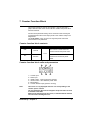
7. Counter Function Block
The Counter function is used to count pulses. It can be reset and a
graphic element used as the contact will show whether the preset value
has been reached.
Function block parameter setting can be accessed: when entering the
coil that represents the counter input (CCN° in the notation used) in the
diagram line.
The "PARAMET." menu is used to change the preset value if the
function block is not padlocked.
Counter function block contacts
Representation
CN°
Function
N°
Description
The contact is closed when the
counter reaches the preset value.
Normal
1 to 8
cN°
The contact is closed until the
counter has reached its preset
value.
Reverse
Counter function block coils and parameters
1
2
3
6
5
4
1 – Counter input
2 – Reset input
3 – Validity output - when the preset is reached
4 – Value to reach - also called the preset value
5 – Block locking.
6 – Counter direction input (up/down counting)
Note:
This screen is only displayed when the coil corresponding to the
counter input is entered.
The only parameter that can be changed is the preset value. Its value
is between 0 and 9999.
When a point is displayed in this screen, it indicates that the element
was not used in the diagram lines.
Smart Relay - Chapter 4
41
7. Counter Function Block
Element
CC
RC
Description/Use
Used as a coil in a Ladder diagram, this
element represents the block’s counter
input. Each time the coil is triggered, the
counter increments or decrements by 1,
depending on the chosen counting
direction.
Used as a coil in a Ladder diagram, this
element represents the reset input for the
Counter block. Triggering the coil will reset
the current count value to zero.
Example
Application example:
Counting on the input to
the Counter N°1 function
block.
I1—————— CC1
Application example:
Resets Counter N°1 when
the Up Arrow key is
pressed on the arrow
keypad.
Z1—————— RC1
DC
p=0000
C or c
Used as a coil in a Ladder diagram, this
element represents the counter input that
determines the direction of counting. If this
coil is triggered, the function block
downcounts. The function block upcounts
by default (this input is not wired).
Value to reach. This value is also called the
preset value. When the current counter
value equals the preset value, then
Counter contact C is closed. This value can
be changed from the previously described
screen and also from the "PARAMET."
menu.
This parameter is used to lock the Counter
function block. When the block is locked,
the preset value no longer appears in the
"PARAMET." menu.
Used as a contact, this Counter function
block element indicates that the preset
value and the current value are equal.
Application example: Up
or downcounting
depending on the state of
a smart relay input.
I2—————— DC1
Application example:
Lighting an indicator light
connected to smart relay
output 1 when the preset
value is reached. Else the
indicator light is out.
C1——————
42
Q1
Smart Relay - Chapter 4
8. Timer Function Block
The Timer function is used to delay, prolong and control actions during
a set period of time. It has a reset input, a command input and an output
used to indicate time-out.
The function block’s parameter settings can be accessed when entering
the control coil (TTN° in the notation used) in the diagram line.
The "PARAMET." menu is used to change the preset value if the
function block is not padlocked.
Timer function block contacts
Representation
Function
TN°
Normal
ttN°
N°
Description
1 to 8
The operation of this output depends
on the Timer parameter settings.
The possible parameter settings are
described in the remainder of this
Sub-section.
Reverse
Timer function block coils and parameters
1
7
3
2
6
4
5
1 – Timer control input
2 – Timer reset input
3 – Control output (or when the Preset time is reached)
4 – Type of Timer (8 possible types, refer to the next page)
5 – Preset time unit.
6 – Preset time, the time value to be reached
7 – Timer preset value lock
Note:
This screen is only displayed when the coil corresponding to the
Timer control input is entered.
When a point is displayed in this screen, it indicates that the element
was not used in the diagram lines.
Smart Relay - Chapter 4
43
8. Timer Function Block
Element
TT
RT
Type
t=00.00
s
T or t
44
Description/Use
Used as a coil in a Ladder diagram, this element represents the Timer
function block control input. Its operation depends on the type selected
(refer to the table on the next page for further details).
Used as a coil in a Ladder diagram, this element represents the reset
input. Triggering the coil will reset the current Timer value to zero. The T
contact is disabled and the block is ready for a new timer cycle.
There are 8 types of Timer. Each type triggers a specific kind of operation
used to handle all possible cases in an application.
The table on the next page provides a detailed description of these 8
types.
Preset value, or the timer value to be reached. The effect of this value
varies depending on the type used (refer to the table on the next page for
further details).
Preset value time unit. There are four possible cases:
1/100 ths. of a second: 00.00 s
Maximum: 99.99
1/10 ths. of a second: 000.0 s
Maximum: 999.9
Minutes: seconds: 00:00 M:S
Maximum: 99 :59
Hours: minutes: 00:00 H:M
Maximum: 99 :59
This parameter is used to lock the Timer function block preset value.
Once locked, the preset value is no longer displayed in the
"PARAMET." screen..
Used as a contact, this function block element represents the Timer
output. Its operation depends on the type selected (refer to the table on
the next page for further details).
Smart Relay - Chapter 4
8. Timer Function Block
Type
Description
Type A: Trigger delay (working contact delay).
Example: To delay triggering a contactor to limit the
current level required.
Type a: Trigger delay on a pulse rising edge with reset.
Type C: Trigger delay (idle contact delay). Example: To
maintain fan operation after stopping the engine.
Type B: Calibrated pulse on the control input rising edge
(passage contact). Example: To trigger a timed lighting
circuit using a pushbutton and a timer.
Type W: Calibrated pulse on the control input falling
edge. Example: Closing a toll gate.
Type D: Symmetrical blinker. Example: Indicating a
failure using a flashing light.
Type d: Symmetrical blinker triggered by the rising edge
on the control input with a Reset function. Example: A
pulse triggered brake control function after power is cut.
Type T: A totalizing count with Reset. Example: To
request the replacement of a filter when the
recommended service life is exceeded.
Smart Relay - Chapter 4
45
8. Timer Function Block
Example - Using a Timer function block
Implementing a stairway lighting timer:
The pushbuttons on each floor are connected to smart relay input I1.
The Timer N°1 function block, set for a two minute, thirty second
duration, controls output Q4.
Output Q4 is connected to the lighting system.
The Ladder diagram lines are as follows:
I1—————— TT1
T1—————— Q4
When entering TT1 the Timer function block parameters must be set.
Note:
The following keys are used, Sel./OK to select or validate a
parameter, Z1 and Z3 to change the value of the selected parameter,
Z2 and Z4 to move from one parameter to another.
Screen
Comment
This is the first screen. First select the
type of Timer function block.
Once the type of Timer function block is
selected: type B, calibrated pulse. Now
select the time base.
Once the time base is selected M: S.
Now enter the required duration.
Once the duration has been selected,
parameter setting is complete. Press
Esc. to return to diagram line entry.
Note:
46
To start the timer, do not forget to set the smart relay to RUN.
Smart Relay - Chapter 4
9. Analog Function Block
The analog function blocks can be used with the following smart relay
references: SR1A121BD, SR1B121BD, SR1A221BD and SR1A221BD.
These are DC supplied smart relays. These modules allow the use of
two discrete inputs, IB and IC in the notation used, and they can accept
input values from 0 to 10V.
Analog function block are used to compare a measured analog value
with an internal reference value and also to compare two measured
analog values. This analog function is used in the form of a contact.
Function block parameters can be set: when the contact representing
the Analog function block (AN°) is entered in the diagram line.
The "PARAMET." menu lets the user change the reference or
hysteresis value depending on the type of function block chosen.
Analog function block contacts
Representation
Function
AN°
Normal
aN°
Note:
Reverse
N°
Description
1 to 8
The contact shows the position of a
measured analog value in relation to
a reference value or it represents a
comparison between two measured
analog values. It’s value depends on
the type of Analog function block
chosen and configured.
An analog function block is only used as a contact.
Smart Relay - Chapter 4
47
9. Analog Function Block
Analog function block parameters
When entering a contact in a diagram line, the user must state the type
of analog function block used. Each type has its own specific parameters
and operating mode as shown in the table below.
Type of Function Block
Description
Contact A1 is closed when the value of analog input IB
does not exceed the reference voltage entered in the Ref.
field, 4.9 V in this example.
Contact A1 is closed when the value of analog input IB
equals or exceeds the reference voltage entered in the
Ref. field, 4.9 V in this example.
Contact A1 is closed when the value of analog input IC
does not exceed the reference voltage entered in the Ref.
field, 4.9 V in this example.
Contact A1 is closed when the value of analog input IC
equals or exceeds the reference voltage entered in the
Ref. field, 4.9 V in this example.
Contact A1 is closed when the value of analog input IB
does not exceed the value of analog input Ic.
Contact A1 is closed when the value of analog input IB
equals or exceeds the value of analog input IC.
Contact A1 is closed when the value of analog input IB is
between IC-H and IC+H.
H (the hysteresis) is entered in the H field, 4.9 V in this
example.
The is used to lock the Analog function block. If this block is locked,
the reference voltage or the hysteresis value (depending on the chosen
type) no longer appears in the "PARAMET." menu.
When the block is unlocked, the admissible values are between 0 and
9.9 Volts.
48
Smart Relay - Chapter 4
Smart Relay - Chapter 4
49
Chapter 5 - Contents
Entering Ladder Diagrams
This Chapter covers the following subjects:
1. Editor Environment ______________________________________________ 51
2. Element Entry Method ___________________________________________ 52
Entering a new element ___________________________________________ 52
Changing an element _____________________________________________ 52
Deleting an element _____________________________________________ 52
3. Link Entry Method _______________________________________________ 53
Entering links between elements ____________________________________ 53
Deleting links between elements ____________________________________ 53
Replacing a link with a contact ______________________________________ 53
4. Function Block Parameter Entry Method ____________________________ 54
5. Deleting and Inserting Ladder Diagram Lines ________________________ 55
Deleting a Ladder diagram line _____________________________________ 55
Inserting a Ladder diagram line _____________________________________ 55
50
Smart Relay - Chapter 5
1. Editor Environment
A Ladder diagram is entered into the smart relay using the front panel
keys. The key functions are listed in the table below:
Key
Description
Press this key to delete an element or a Ladder diagram
line.
Press this key to insert a Ladder diagram line.
Press this key to:
- Make a selection,
- Edit an element’s parameter page,
- Edit a display page,
- Validate a selection made.
For example, when a blinking is displayed while
entering a diagram, pressing this key will call-up the
"selection" mode used to choose the required contact or
coil.
Press this key to exit the current screen after making the
required changes or to cancel the current Ladder
diagram entry.
For example, after changing a function block’s
parameters, press this key to return to diagram entry
mode.
When entering a diagram, using the arrow key pad lets
the user move from one element to another using the Z4
and Z2 keys, and then changing the element’s value
using the Z1 and Z3 keys.
In the remainder of this Chapter, these keys will be referred to as Del.,
Ins. Line, Sel./ OK, Esc.,Z1, Z2, Z3 and Z4.
Smart Relay - Chapter 5
51
2. Element Entry Method
Entering a new element
It is only possible to position an element (contact or coil) when the
blinking cursor is displayed on screen.
Contact entry is performed in the three left hand columns, coils can only
be entered into the last column.
Entering a contact
1- Place the blinking cursor in the required position.
2- Press Sel./ OK.
3- Choose the required element using the Z1 and Z3 keys.
4- Use the Z2 key to call-up the number.
5- Choose the number using keys Z1 and Z3.
6- Press Sel./ OK or Z2 to validate.
Entering a coil
1- Place the blinking cursor in the required position.
2- Press Sel./ OK.
3- Choose the required element using the Z1 and Z3 keys.
4- Use the Z2 key to call-up the number.
5- Choose the number using keys Z1 and Z3.
6- Use the Z2 key to move to the type of coil.
7- Choose the type of coil using keys Z1 and Z3.
8- Press Sel./ OK to validate.
Validating certain function block coils will bring-up a block parameter
setting screen. For information on parameter characteristics, refer to
Chapter 4, page 30. For information on the data entry methodology, refer
to Sub-section 4, page 54 in the current chapter.
Changing an element
To change an element in an existing Ladder diagram, simply move to the
element to change and follow the same procedure as when entering a
new element.
Deleting an element
To delete an element, simply place the cursor on the required
element, then press Del. Generally, the deleted element must be
replaced by a link.
52
Smart Relay - Chapter 5
3. Link Entry Method
Entering links between elements
In most cases, links are automatically entered by the smart relay.
However, to enter a link manually, proceed as follows.
Links can only be entered when the z blinking cursor is displayed.
1- Place the z blinking cursor at the desired location.
2- Press Sel./ OK to start the link ("+" cursor).
3- Move the cursor to the desired location using the Z1, Z2, Z3 or Z4
keys.
4- Press Sel./ OK to validate. The link is drawn.
Repeat this action as many times as necessary to link the elements
together as required.
Deleting links between elements
To delete a link, simply move the z or
and press Del.
cursor onto the link to delete
Replacing a link with a contact
To replace a link with a contact, simply place the cursor at the required
location and enter the contact as described on the previous page.
Smart Relay - Chapter 5
53
4. Function Block Parameter Entry Method
When entering a Ladder diagram, the function block parameters must be
filled in. These parameter setting screens are displayed for:
Entering a Clock function block,
An Analog function block,
A command input to a Timer function block,
A count input to a Counter function block.
Regardless which screen is displayed, the parameter setting principle is
the same:
1-Use the Z4 and Z2 keys to move the cursor onto the parameter to
change.
2-Select the parameter by pressing Sel./ OK.
3-Change the parameter value using the Z1, Z2, Z3 and Z4 keys.
4-Finish data entry by pressing Esc. to return to Ladder diagram entry.
54
Smart Relay - Chapter 5
5. Deleting and Inserting Ladder Diagram Lines
Deleting a Ladder diagram line
Ladder diagram lines are deleted line by line. Proceed as follows:
1-Move the cursor to a blank space in the line (where there are no links
or elements), if necessary, delete an element to create the necessary
blank space.
2- Press Del.
3- A delete validation menu is brought up. Select the appropriate choice
using the Z1 and Z3 keys.
4- Validate the choice by pressing Sel./ OK.
The line is deleted.
Note:
It is possible to delete all of the Ladder diagram lines stored in a
smart relay. To do this, call up the "CLEAR PROG" option in the
main menu and validate the deletion of all Ladder diagram lines.
Inserting a Ladder diagram line
To insert a Ladder diagram line, simply move to the line immediately
above the one to create and press Ins. Line.
Smart Relay - Chapter 5
55
Chapter 6 - Contents
Debugging
This Chapter covers the following subjects:
1. Introduction ____________________________________________________ 57
2. Dynamic Mode Ladder Diagrams __________________________________ 58
Displaying Ladder diagrams _______________________________________ 58
Changing Ladder diagrams ________________________________________ 58
Using Z keys as push buttons ______________________________________ 58
3. Dynamic Mode Function Block Parameters __________________________ 59
Displaying function block parameters ________________________________ 59
Changing function block parameters _________________________________ 60
4. Dynamic Mode Menus ___________________________________________ 61
56
Smart Relay - Chapter 6
1. Introduction
Once an application has been entered in Ladder diagram form,
debugging tests still remain to be run.
The first step is to set the smart relay to RUN. To do this, select the
"RUN/STOP" option from the main menu and validate the RUN mode
selection.
From this moment on, the smart relay handles the physical inputs and
outputs according to the instructions entered in the Ladder diagram.
1
2
3
4
1-Display input status (B and C represent the
analog inputs)
2-Display the operating mode
(RUN/STOP)
3-Display a parameter, by default the day and time
for products with a clock function
4-Display the output status
When inputs or outputs are active, they appear in reverse video mode
(using black on a white background).
From this moment on, the term "dynamic operation" refers to the use of
smart relay functions. In this publication, the terms RUN and dynamic
have a similar meaning.
Smart Relay - Chapter 6
57
2. Dynamic Mode Ladder diagrams
Displaying Ladder diagrams
The smart relay can dynamically display the performance of a Ladder
diagram. To do so, simply call up the "PROGRAM" option and select the
lines to display using the cursor key pad.
Each closed contact or energized coil is displayed in reverse video mode
(using white on a black background).
To change smart relay performance, the user can change or display
some of the function block parameters.
Changing Ladder diagrams
Note:
It is ABSOLUTELY IMPOSIBLE to change Ladder diagram lines in
RUN mode.
It is however possible to change function block parameters.
In RUN, the Del. and Ins. Line keys are not available.
The Sel/Ok key is only usable for function blocks.
Using Z keys as push buttons
When the menus are called up, the Z keys can no longer be used as
pushbuttons. To test the Ladder diagram in dynamic mode and observe
the effect of the Z keys, the user must:
1- Display the Ladder diagram (see below).
2- Press the Sel./OK key.
To disable pushbutton mode operation, simply press the Esc key.
58
Smart Relay - Chapter 6
3. Dynamic Mode Function Block Parameters
Displaying function block parameters
In RUN mode, new functions are offered. It is therefore possible to
display function block parameters.
The following elements can be displayed:
1- The current value and preset value of a Counter.
2- The status of Counter inputs and outputs.
3- The current value and preset value of a Timer.
4- All of the parameters of a Clock function block.
5- The reference voltage for an Analog function block.
6- The hysteresis value for an Analog function block.
7- The values measured on the analog inputs.
To do this, simply call up the "PROGRAM." option and select the
required function block, then press Sel./ OK.
A new screen is brought up with the function block’s parameters. The
procedure is the same as the one used to change function block
parameters.
Screen example:
Screen
Parameters that can be displayed
Counter contact state
Counter coil state
Current counter value
Counter preset value
Compared voltage level values
Reference value
Type of Analog function block
Timer contact state
Timer time out
Preset duration value
Smart Relay - Chapter 6
59
3. Dynamic Mode Function Block Parameters
Changing function block parameters
In RUN mode a Counter preset value can be changed dynamically if it is
not locked.
The following actions are allowed:
1- Changing a Counter preset value.
2- Changing a Timer preset value.
3- Changing Clock function block parameters.
3- Changing the reference voltage for an Analog function block.
4- Changing the hysteresis value for an Analog function block.
To do this, the simplest way is to:
1- Select "PARAMET." from the main menu,
2- Press Sel./ OK,
3- Choose the required parameter using the Z1 and Z3 keys,
4- Press Sel./ OK,
5- Modify the parameter value using the Z2, Z3 and Z2, Z4 keys,
6- Validate by pressing Sel./ OK.
It is also possible to change a parameter value by selecting the
"PROGRAM" function, and then selecting the required function block
by pressing Sel./ OK.
60
Smart Relay - Chapter 6
4. Dynamic Mode Menus
Some menus are accessible in RUN mode, while others are not. Here is
a summary table.
Menu
Access in
STOP mode
Access in
RUN mode
TIME SET
Yes
Yes
PROGRAM.
Yes
Yes*
PARAMET.
Yes
Yes
VISU.
Yes
Yes
RUN/STOP
Yes
Yes
CONFIG.
Yes
Yes
CLEAR PROG
Yes
No
TRANSFER.
Yes
No
PROG. INFO.
Yes
Yes
Configuration menu
PASSWORD
Yes
Yes
LANGUAGE
Yes
Yes
Enter
Yes
No
Zx=KEYS
Yes
No
HELP
Yes
Yes
* Some functions are accessible, others not. Refer to the previous Sub-sections
Smart Relay - Chapter 6
61
Chapter 7 - Contents
Application Example
This Chapter covers the following subjects:
1. Specifications __________________________________________________ 63
2. Specification Analysis ___________________________________________ 64
3. Implementing the solution ________________________________________ 65
Implementing the Ladder diagram ___________________________________ 65
Setting function block parameters ___________________________________ 66
62
Smart Relay - Chapter 7
1. Specifications
To enhance and centralize the control system in the underground car
park of an administrative building. The vehicle entrance and exit to and
from the car park are controlled by a typical automatic barrier that
handles the normal standard functions such as opening and closing time
delays to allow vehicles to pass, processing payment tickets, a built-in
security interphone, external barrier locking in the closed position...
In addition, the new specification calls for adding a function to count the
number of vehicles in the car park and control a light up display informing
users that all of the parking spaces are taken and stopping new entries
by locking the barrier in the closed position. Drivers then know to look for
a parking space elsewhere. It must also be possible to override this
function when it is necessary to allow the emergency services to
intervene (fire department, doctors...).
The specification also calls for being able to inhibit access to the car park
lot outside of working hours and to allow the security personnel to
override this function for exceptional events. The normal working hours
are: Monday to Friday, from 08:30 to 17:00, Saturday, from 09:30 to
12:00 and complete closure on Sundays.
For safety reasons, it is also necessary to exhaust toxic emissions such
as CO2 using a fan when the concentration levels measured exceed
permissible levels (using a dedicated sensor that provides an output
value between 0 and 10 V).
There is also a requirement to control lighting triggered by a vehicle
arriving and through push button switches placed near all of the
pedestrian access points. For power saving reasons, the lighting will be
switched off after a delay of ten minutes, normally providing enough time
for a user to park, leave their vehicle and take the elevator or to return to
their vehicle and leave the parking lot.
To complement this system, manual intervention should allow updating
the number of vehicles in the car park by incrementing or decrementing
the number of vehicles as determined by the smart relay.
Smart Relay - Chapter 7
63
2. Specification Analysis
Smart relay label
Description
Input I1
Vehicle entry detection.
Input I2
Vehicle exit detection.
Counter C1
Counting the number of vehicles in the
car park (93 maximum).
Output Q1
Car park full indicator
Output Q2
Entry barrier locking (inhibits entry barrier
opening) when the car park is full or
outside of office hours.
Function key Z4
Manual entry release.
Function key Z2
Resume automatic entry control.
Function key Z1
Manual incrementation of the number of
vehicles in the car park.
Manual decrementation of the number of
vehicles in the car park.
Function key Z3
Clock function block N°1
Managing car park access hours.
Inputs I3 and I4
Pushbuttons at pedestrian access points
used to light car park lighting. One for the
elevator and one for the stairway (no
pedestrian access is allowed via the
vehicle entry).
Output Q3
Lighting control.
Timer function block N°1
Lighting timer
(10 minutes).
Analog input IB
CO2 level sensor
Analog function block A1, the authorized
threshold value corresponds to 8.5 Volts.
Comparison of the CO2 measurement
with the authorized threshold.
Output Q4
Polluted air extraction fan control.
Timer function block N°2
Fan timer
(15 minutes).
Note:
64
To implement this solution, a smart relay with analog inputs, Clock
function blocks and at least 4 discrete inputs and outputs is
required. The ideal smart relay is an SR1 B 12 1 BD.
Smart Relay - Chapter 7
3. Implementing the Solution
Implementing the Ladder diagram
Counting vehicles in, subtracting vehicles out
and manually updating the number of
vehicles actually in the car park.
Starting the lighting timer.
Starting the fan timer.
Handling manual release.
Controlling outputs: Car park full indicator,
blocking the entry, lighting the car park and
fan extraction.
Note:
When upcounting and downcounting, the counter locks up when the
car park becomes full (no spurious detection or counting actions
take place if vehicles are allowed to enter in manual release mode).
IMPORTANT: In a given counter, coils CC and DC must only appear
once in a Ladder diagram.
In addition, output Q2 is triggered when entry into the car part is
inhibited. This leads to the use of an auxiliary relay to manually lock
or unlock the access barrier using the cursor keys.
Smart Relay - Chapter 7
65
3. Implementing the Solution
Setting function block parameters
Function block
Comments
Counter function block C1
Clock function block
The preset value is 93 (the maximum
number of vehicles allowed in this car
park). Where necessary, this value can
be changed during operation.
1
Opening hours: Monday to Friday from
08:30 to 17:30, Saturday from 09:30 to
12:00 and closed all day on Sunday. Two
ranges are used.
Timer function block T1
Car park lighting timer duration (10
minutes).
Analog function block A1
Comparison between the measured CO2
value and the threshold value (8.5 V).
Timer function block T2
Fan operating duration if the CO2
threshold is exceeded.
66
Smart Relay - Chapter 7
Smart Relay - Chapter 7
67
Chapter 8 - Contents
Troubleshooting
This Chapter covers the following subjects:
1. Smart Relay Messages ___________________________________________ 69
2. Frequently Asked Questions ______________________________________ 70
68
Smart Relay - Chapter 8
1. Smart Relay Messages
Explanation of the messages returned by the smart relay. These
messages generally indicate incompatible actions requested by the
user.
Message
Cause
Corrective action
Return to the main menu,
select the "RUN/STOP"
option, set the relay to STOP
mode, then return to where
the message occurred.
Go to the diagram to ensure
that it was entered correctly
and that it comprises
elements with parameters
that can be set: Counters,
Timer, Time/Date functions,
Analog function blocks.
ERR. RUN MODE
The user requested access to
a function that is only
available when the smart
relay is stopped.
NO PARAMET.
The user requested access to
the "PARAMET." option
when no parameter is
available (the diagram does
not comprise any elements
with parameters).
NO PARAMET.
The user requested access to
the "VISU." option when no
element that can be displayed
has been entered in the
diagram.
Go to the diagram to ensure
that the diagram was entered
correctly and that it comprises
at least one function block.
PROGRAM.
INCOMPAT.
The user requested the
transfer of a program that
does not match the
characteristics of the target
smart relay, e.g. clocks are
used when the target smart
relay does not have any.
Check the origin of the
program to transfer and
choose a program that is
compatible with the
appropriate smart module.
TRANSF.ERR.
A transfer was in progress
and the link with the PC went
down unexpectedly.
Refer to the documentation
for the smart relay PC
programming application
ZelioSoft.
TRANSF.ERR.
A transfer to the EEPROM
was requested and the
EEPROM is not present or
incorrectly located.
Check for the presence and
correct location of the
EEPROM.
Smart Relay - Chapter 8
69
2. Frequently Asked Questions
To assist the user in understanding the smart relay, the table below
details frequently asked questions.
Question
I cannot access some
parameters
I still cannot access some
parameters
When I try to change a
parameter, the Z1 and Z3 keys
on the arrow key pad do not
work.
I cannot STOP my smart relay
despite validating the RUN/
STOP option in the main menu
using the Sel./ OK key.
My Ladder diagram comprises
67 lines and it takes quite a
long time to reach the last line.
What can I do to speed things
up?
I would like to change my
diagram lines but the Sel./ OK
key no longer works.
When I try to change my
Ladder diagram lines, the
smart relay shows me a blank
screen, have I lost everything I
did?
70
Answer
Some parameters are not accessible, refer to the
documentation to determine whether these
elements can be changed. Example of an element
that cannot be changed: Counter function block
counting direction. This element is only accessible
by wiring in a diagram line.
To access the parameters, use the Z4 and Z2 keys
on the arrow key pad to select them (the Z1 and Z3
keys are only used to change their value). Then
press Sel./ OK to change the selected element
using the Z1 and Z3 keys.
This is normal, to enter the modification mode, first
press Sel./ OK (the parameter blinks). Then the Z1
and Z2 key become effective.
BE SURE to correctly read the message text and
confirm the correct option.
To move around faster, simply press on the Z1 or Z3
keys on the arrow key pad for a longer time. You can
then scroll 5 lines at a time.
Ensure that the smart relay is indeed stopped.
Changes in RUN mode are not allowed.
Not necessarily, this situation may occur if blank
lines have been inserted at the start of the Ladder
diagram. Press Z3 to check whether your program
lines are not located further down.
Smart Relay - Chapter 8
2. Frequently Asked Questions
Question
I have a Counter function block
called C1 used in a Ladder
diagram line to count and it
downcounts on another line.
Only the downcount function
works. Why?
I have forgotten my password
and I can no longer access my
smart relay functions. What
can I do?
I have a Ladder diagram that
uses a Z key as a push button.
I would like to test it but when I
display the Ladder diagram in
on-line mode, the Z key is no
longer operational. What can I
do?
I generated a Ladder diagram
on a module with a clock
function, can I transfer to the
EEPROM in a module without
a clock?
When entering a Ladder
diagram, the clock function
blocks do not appear when
choosing the contacts. Is this
normal?
When entering a Ladder
diagram, the analog function
blocks do not appear when
choosing the contacts. Is this
normal?
Smart Relay - Chapter 8
Answer
This is perfectly normal, a Counter’s CC coil must
appear once and once only in the Ladder diagram.
To understand the method, refer to the example in
Chapter 7.
To delete a password, move to the password entry
screen and type the following key sequence: Z1,
Z4, Z3, Z2.
To use the Z keys as push buttons when displaying
a ladder diagram in real-time mode, simply press
Sel.OK when displaying the diagram. To disable the
push button mode, simply press Esc.
Yes this is possible if your Ladder diagram does not
use Clock function blocks.
It is highly probable that the module is one not fitted
with a clock and as a result, the clock function blocks
cannot be accessed. Check the product reference
number.
It is highly probable that the module does not have
any analog inputs and as a result the analog
function blocks cannot be accessed. Check the
product reference number.
71
Chapter 9 - Contents
Transferring Ladder Diagrams
This Chapter covers the following subjects:
1. How to Transfer an Application ____________________________________ 73
Smart relay -> PC Transfer ________________________________________
PC -> Smart relay transfer _________________________________________
Smart relay -> EEPROM transfer ___________________________________
EEPROM -> Smart relay transfer ___________________________________
72
73
73
74
74
Smart Relay - Chapter 9
1. How to Transfer an Application
Smart relay -> PC transfer
The Zelio smart relay can be configured and programmed using the
ZelioSoft program. This transfer function lets the user retrieve an
application from a smart relay using the program.
The following method is used:
1- Select the "TRANSFER." function from the main menu.
2- Press the Sel./ OK key to validate.
3- Select the "Modul.->PC" function.
4- Press the Sel./ OK key to validate.
5- Enter the password if necessary.
6- The smart module displays "READY", and the transfer is performed
as soon as the program is ready.
PC -> Smart relay transfer
This transfer function is used to load an application developed using
ZelioSoft into a smart relay.
The following method is used:
1- Select the "TRANSFER." function from the main menu.
2- Press the Sel./ OK key to validate.
3- Select the "PC->Modul." function.
4- Press the Sel./ OK key to validate.
5- When prompted to "Change Prog?", select the answer "YES" by
pressing the Z1 key.
6- Press the Sel./ OK key to validate.
7- The smart relay displays "READY", the transfer is performed as
soon as the software requests it.
Smart Relay - Chapter 9
73
1. How to Transfer an Application
Smart relay -> EEPROM transfer
The smart relay has an optional EEPROM. This function lets the user
load the application in the Zelio smart relay into the EEPROM.
The following method is used:
1- Select the "TRANSFER." function from the main menu.
2- Press the Sel./ OK key to validate.
3- Select the "Modul.->Mem" function.
4- Press the Sel./ OK key to validate.
5- Enter the password if necessary.
6- The smart relay displays "Modul. >>>" then "TRANSFER OK",
the transfer is done.
Note:
The EEPROM can then be used to load an application into another
smart relay.
EEPROM -> Smart relay transfer
This transfer is used to reload an application into a Zelio smart relay. It
avoids the need to re-enter an existing application.
The following method is used:
1- Select the "TRANSFER." function from the main menu.
2- Press the Sel./ OK key to validate.
3- Select the "Mem->Modul." function.
4- Press the Sel./ OK key to validate.
5- When prompted to "Change Prog?", select the answer "YES" by
pressing the Z1 key.
6- Press the Sel./ OK key to validate.
7- The smart relay displays ">>> Modul." then "TRANSFER OK",
the transfer is done.
74
Smart Relay - Chapter 9
Smart Relay - Chapter 9
75
Appendix - Contents
This Chapter covers the following subjects:
1. Forms _________________________________________________________ 77
Clock function block _____________________________________________
Counter function block ____________________________________________
Timer function block _____________________________________________
Analog function block ____________________________________________
Arrow keys _____________________________________________________
User’s quick reference ____________________________________________
76
78
78
78
79
79
79
Smart Relay - Appendix
1. Forms
LADDER DIAGRAM
Application: _________________________
Date: ___________ Version:_______
Comments: _________________________
__________________________
__________________________
Title page: _________________________
Smart Relay - Appendix
77
1. Forms
Clock function block
ABCD
ABCD
ABCD
ABCD
-
-
-
-
ON:
ON:
ON:
ON:
OFF:
OFF:
OFF:
OFF:
Counter function block
C
C
C
C
DC
DC
DC
DC
T
T
T
T
Type
Type
Type
Type
Timer function block
78
Smart Relay - Appendix
1. Forms
Analog function block
A
A
A
A
Analog
Analog
Analog
Analog
Arrow keys
z1
z4
z1
z2
z3
z4
z2
z3
User’s quick reference
Reminder - Parameter display
To display parameters, press Sel./ OK to bring up the "PARAMET."
menu, then scroll the parameters using the Z1 and Z3 keys.
Reminder - Changing parameters
To change the parameters, simply move to the required parameter in the
"PARAMET." menu, press Sel./ OK, then change the parameter.
Reminder - Using the display screen
To monitor the state of an element on the main screen in real-time: Bring
up the "VISU." menu, move to the element to display, then validate the
selection by pressing Sel./ OK. Return to the main screen by pressing
Esc.
Smart Relay - Appendix
79
80
Smart Relay - Appendix
Index
A
Analog
contact 47
parameters 48
Auxiliary relay 35
C
Calibrated pulse 45
Clock
contact 37
enter 39
operation 37
number 37
parameters 38
summary 40
Coil
counter 41
enter 52
output 33
remote control relay 33, 34
RESET 33, 34
SET 33, 34
Coils
timer 43
Configuration
menu 10, 11
Connection
PC 3
discrete 5
Contact
analog 47
clock 37
counter 41
entering 52
input 32
output 33
timer 43
Counter
contact 41
decrementing 42
incrementing 42
number 41
parameters 41
preset 42
reset 42
D
Date
modify 8, 10
Debugging 57
Delete
element 6
Ladder diagram 10
line 6
program 10
Diagnostic 69
Display 3
menu 10
E
EEPROM
location 3
transfer 10
Electrical diagram
notation 16
ERR. RUN MODE 69
Example
specifications 63
F
Fast input
menu 11
Filtering 27
Function
Init. 26
Function block
analog 47
clock 37
counter 41
timer 43
H
Help
automatic 29
menu 10, 11
Hysteresis 48
I
Ib 48
Ic 48
Ini. 7
Inputs
analog 3, 4, 48
connection 5
contact 32
current 4
discrete 4, 32
display 3, 57
fast 27
filtering 11
number 4, 32
voltage 4
Insert line 6
K
Key
arrow 3
delete 3, 6
escape 3, 6
insert 3, 6
pushbutton 3, 58
selection 3, 6
Z 36, 58
Keys
contact 28
menu 11
Z 28
L
Label 3
Language
choice 7
menu 11
modifying 26
number 26
Link
entering 53
Lock 29
M
Main menu
access 6
description 9
Menu
in RUN mode 61
Messages 69
Modify
field 8
element value 8
Mounting 3
N
NO PARAMET. 69
O
Operating ranges 38
Outputs
coil 33
contact 33
discrete 33
number 4, 33
relay 4
P
Parameters
analog 48
display 3, 57
Clock function block 38
counter 41
display in RUN mode 59
enter 54
menu 10
modify 60
timer 43
Password
cancel 25
effect 25
enter 25
menu 11
modify 25
Power supply
general 3
value 4
Preset
counter 42
timer 44
PROGRAM. INCOMPAT. 69
Program
menu 10
Q
Questions (FAQ) 70
R
Remote control relay 33
RUN
displaying 3, 57
menu 10
setting to RUN 21
S
Symmetrical blinker 45
Ladder diagram
delete 55
display in RUN mode 58
entry 18
example 65
insert 55
nbr. of lines 31
notation 16
operation 13
STOP
menu 10
set to 21
T
Terminal block
inputs 3
outputs 3
Time
modifying 8
Time base
timer 44
Time out
idle 45
working 45
Timer
command 44
contact 43
number of 43
parameters 43
preset 44
reset 44
time base 44
type 44, 45
Total 45
TRANSF.ERR 69
Transfer
EEPROM 10, 74
PC 10, 73
Two-way switch
enter 18
V
Validate 6
Z
Z keys
display 3
The products, equipment and services presented in this document are subject to change in their presentation, operating
or usage characteristics. Their description cannot be considered contractually binding.
© Copyright Telemecanique 2000. All rights reserved. This document may not be reproduced or copied, in whole or in
part, in any form or by any means, graphic, electronic, mechanical or other, including photocopying, recording or storage
in a retrieval system.
SR1 MAN01EN
01/ 2000
W9 156 9786 0211 A01