1
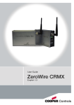
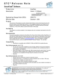
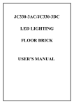
Wide Low Input Voltage
DMX512 Decoder
User Manual
DMX512 Color Perfect Solution
Picture for illustration only
High Power DMX Decoder & Driver
Model No.: PX24500 (wide input voltage, constant voltage output)
Meets DMX 512/1990 Protocol
PX24500 can drive 5A (Each Channel)
Capable of driving many kinds of RGB LED lamps and luminaires
DMX Decoder Specification
1 of 5
INTRODUCTION
Thank you for choosing PX24500 DMX512 decoder. With advanced micro-computer control
technology, PX24500 convert the widely used DMX512/1990 signal to analog signal. It
allows user to choose 1~3 output channel, 256-level brightness control. This compact decoder
connects to light console and analog device, RGB LED lamps or lighting & building lamps allowing
its user to create endless possibilities of light shows.
FEATURES
◆
◆
◆
◆
◆
◆
◆
◆
◆
◆
◆
Meets DMX512/1990 Protocols. Also compatible to DMX512a protocols.
256-level brightness, full-color control
3 output channels
PX24500 can drive 5A current (each channel)
Compatible with any DMX512 controller to produce perfect lighting effects.
Capable to drive 1 - 3 channel of lamps
Can set the DMX addesses freely
Indicator light of each channel state within(optional)
Modular design, can be combined with LED luminaires neatly
Low input voltage, safe to operate.
Custom-made size is available
TECHNICAL CHARACTERISTICS
Decode Channel: 1~3
Input Signal:
DMX-512/1990 digital signal
Output Signal:
0~24V PWM signal
Power Supply:
6~25V DC
Power Output
<360W
Power Dissipation:<1W
Operating Temp.: 0~70℃
Size:
175mm X 45mm X 35mm,Custom size available
Weight:
≤300g
DIMENSION
DMX Decoder Specification
2 of 5
INTERNAL BLOCK DIAGRAM (Example: PX24500)
APPEARANCE
(1) DMX signal input interface (RJ11)
(2) DMX signal output interface (RJ11)
(3) Address setting interface
(4) Driver output interface
(5) Power input interface
INTERFACE INTRODUCTION
◆
DMX signal interface
1: No Connection
2: Data +
3: Data 4: Ground
◆
Address setting interface
Please find the detailed instruction for Address setting at Page 5.
◆
Power input interface
DC 6-25V input for decoder and lamp
◆
Driver output interface
Common anode, V+ and R,G,B interface, can drive kinds of RGB module or single-color module,
Can regulate output current according to the actual load
DMX Decoder Specification
3 of 5
HOW TO USE
PX24500 is controlled by DMX-512 digital signal. The frontage is DMX512 transmitter,
take EC-DMX512 for example, to control 0~24V analog devices.
The connection is below:
TYPICAL APPLICATIONS (RGB LED)
◆
Circuit Diagram 1
Connection of DMX-512 Signal
◆
◆
The wire for DMX signal is STP, the DMX signal has positive and negative signal.
Pay attention to the polarity while soldering. Connect the positive signal, negative
signal and GND to the corresponding signal of PX24500.
Connect a signal terminal at the end of the whole connetion.
DMX Decoder Specification
4 of 5
Power Rating Calculation
This product has a wide input/output voltage(DC 6-25V), it's rating current is 5A, so the rated
power is different in different input voltage, for example:
Rating power in 12V:12V X 5A X 3 = 180 W
Rating power in 24V:24V X 5A X 3 = 360 W
DMX-512 Address Setting
The DIP switch on PX24500 can set the binary value of the DMX512 address to
receive data.
The correlative bits is the 1-9 bits of the DIP switch, the 1st bit is LSB, the 9th
bit MSB 512 addesses totally. The start addess is the number of the first channel of the
decoder, the second channel will receive the data of start addess+1, and the third
channel will receive the data of start addess+2. There are two way to find out the
relation between the DIP switch and DMX addess.
Calculation Method:
calculational formula:[the sum of 1~9 bit of the DIP switch] + 1 = DMX start address
Set the n(th) bit of the DIP switch up(set to “1”)to get the value of such bit;
Set the n(th) bit of the DIP switch down “0”, so the value of this bit is 0.
Note:the 10th bit is not use.
DIP
DIP
Value
1
1
2
2
3
4
4
8
5
16
6
32
7
64
8
9
128 256
Example 1: Set to 38
Set the 6th,3rd,1st bit of the DIP switch to “1”, others set to “0”, then the sum
of the 1~9 is 32+4+1, then add 1 to it, is the start address 38.
That is: [ 32 + 4 + 1 ] + 1 = 38
Example 2: Set to 226
Set the 8th, 7th, 6th, 1st bit to “1”, others set to “0”, then the sum of the 1~9 is
128+64+32+1, then add 1 to it, is the start address 226.
That is: [ 128 + 64 + 32 + 1 ] + 1 = 226
DMX-PX Series Rev. 1.0c
Specifications are subject to change without notice.
Copyright © 2006 Brilliance Technologies Co., Ltd. All rights reserved
DMX Decoder Specification
5 of 5